WO2013014762A1 - Cellule de type étanche - Google Patents
Cellule de type étanche Download PDFInfo
- Publication number
- WO2013014762A1 WO2013014762A1 PCT/JP2011/067096 JP2011067096W WO2013014762A1 WO 2013014762 A1 WO2013014762 A1 WO 2013014762A1 JP 2011067096 W JP2011067096 W JP 2011067096W WO 2013014762 A1 WO2013014762 A1 WO 2013014762A1
- Authority
- WO
- WIPO (PCT)
- Prior art keywords
- terminal
- battery
- battery case
- plate
- internal
- Prior art date
- Legal status (The legal status is an assumption and is not a legal conclusion. Google has not performed a legal analysis and makes no representation as to the accuracy of the status listed.)
- Ceased
Links
Images




Classifications
-
- H—ELECTRICITY
- H01—ELECTRIC ELEMENTS
- H01M—PROCESSES OR MEANS, e.g. BATTERIES, FOR THE DIRECT CONVERSION OF CHEMICAL ENERGY INTO ELECTRICAL ENERGY
- H01M50/00—Constructional details or processes of manufacture of the non-active parts of electrochemical cells other than fuel cells, e.g. hybrid cells
- H01M50/30—Arrangements for facilitating escape of gases
- H01M50/317—Re-sealable arrangements
- H01M50/325—Re-sealable arrangements comprising deformable valve members, e.g. elastic or flexible valve members
-
- H—ELECTRICITY
- H01—ELECTRIC ELEMENTS
- H01M—PROCESSES OR MEANS, e.g. BATTERIES, FOR THE DIRECT CONVERSION OF CHEMICAL ENERGY INTO ELECTRICAL ENERGY
- H01M50/00—Constructional details or processes of manufacture of the non-active parts of electrochemical cells other than fuel cells, e.g. hybrid cells
- H01M50/50—Current conducting connections for cells or batteries
- H01M50/531—Electrode connections inside a battery casing
-
- H—ELECTRICITY
- H01—ELECTRIC ELEMENTS
- H01M—PROCESSES OR MEANS, e.g. BATTERIES, FOR THE DIRECT CONVERSION OF CHEMICAL ENERGY INTO ELECTRICAL ENERGY
- H01M50/00—Constructional details or processes of manufacture of the non-active parts of electrochemical cells other than fuel cells, e.g. hybrid cells
- H01M50/50—Current conducting connections for cells or batteries
- H01M50/543—Terminals
- H01M50/552—Terminals characterised by their shape
- H01M50/553—Terminals adapted for prismatic, pouch or rectangular cells
-
- H—ELECTRICITY
- H01—ELECTRIC ELEMENTS
- H01M—PROCESSES OR MEANS, e.g. BATTERIES, FOR THE DIRECT CONVERSION OF CHEMICAL ENERGY INTO ELECTRICAL ENERGY
- H01M50/00—Constructional details or processes of manufacture of the non-active parts of electrochemical cells other than fuel cells, e.g. hybrid cells
- H01M50/50—Current conducting connections for cells or batteries
- H01M50/543—Terminals
- H01M50/564—Terminals characterised by their manufacturing process
- H01M50/567—Terminals characterised by their manufacturing process by fixing means, e.g. screws, rivets or bolts
-
- H—ELECTRICITY
- H01—ELECTRIC ELEMENTS
- H01M—PROCESSES OR MEANS, e.g. BATTERIES, FOR THE DIRECT CONVERSION OF CHEMICAL ENERGY INTO ELECTRICAL ENERGY
- H01M50/00—Constructional details or processes of manufacture of the non-active parts of electrochemical cells other than fuel cells, e.g. hybrid cells
- H01M50/50—Current conducting connections for cells or batteries
- H01M50/572—Means for preventing undesired use or discharge
- H01M50/574—Devices or arrangements for the interruption of current
- H01M50/578—Devices or arrangements for the interruption of current in response to pressure
-
- H—ELECTRICITY
- H01—ELECTRIC ELEMENTS
- H01M—PROCESSES OR MEANS, e.g. BATTERIES, FOR THE DIRECT CONVERSION OF CHEMICAL ENERGY INTO ELECTRICAL ENERGY
- H01M10/00—Secondary cells; Manufacture thereof
- H01M10/05—Accumulators with non-aqueous electrolyte
- H01M10/052—Li-accumulators
- H01M10/0525—Rocking-chair batteries, i.e. batteries with lithium insertion or intercalation in both electrodes; Lithium-ion batteries
-
- H—ELECTRICITY
- H01—ELECTRIC ELEMENTS
- H01M—PROCESSES OR MEANS, e.g. BATTERIES, FOR THE DIRECT CONVERSION OF CHEMICAL ENERGY INTO ELECTRICAL ENERGY
- H01M2200/00—Safety devices for primary or secondary batteries
- H01M2200/20—Pressure-sensitive devices
-
- H—ELECTRICITY
- H01—ELECTRIC ELEMENTS
- H01M—PROCESSES OR MEANS, e.g. BATTERIES, FOR THE DIRECT CONVERSION OF CHEMICAL ENERGY INTO ELECTRICAL ENERGY
- H01M2220/00—Batteries for particular applications
- H01M2220/20—Batteries in motive systems, e.g. vehicle, ship, plane
-
- H—ELECTRICITY
- H01—ELECTRIC ELEMENTS
- H01M—PROCESSES OR MEANS, e.g. BATTERIES, FOR THE DIRECT CONVERSION OF CHEMICAL ENERGY INTO ELECTRICAL ENERGY
- H01M50/00—Constructional details or processes of manufacture of the non-active parts of electrochemical cells other than fuel cells, e.g. hybrid cells
- H01M50/50—Current conducting connections for cells or batteries
- H01M50/531—Electrode connections inside a battery casing
- H01M50/536—Electrode connections inside a battery casing characterised by the method of fixing the leads to the electrodes, e.g. by welding
-
- H—ELECTRICITY
- H01—ELECTRIC ELEMENTS
- H01M—PROCESSES OR MEANS, e.g. BATTERIES, FOR THE DIRECT CONVERSION OF CHEMICAL ENERGY INTO ELECTRICAL ENERGY
- H01M50/00—Constructional details or processes of manufacture of the non-active parts of electrochemical cells other than fuel cells, e.g. hybrid cells
- H01M50/50—Current conducting connections for cells or batteries
- H01M50/543—Terminals
- H01M50/547—Terminals characterised by the disposition of the terminals on the cells
- H01M50/55—Terminals characterised by the disposition of the terminals on the cells on the same side of the cell
-
- Y—GENERAL TAGGING OF NEW TECHNOLOGICAL DEVELOPMENTS; GENERAL TAGGING OF CROSS-SECTIONAL TECHNOLOGIES SPANNING OVER SEVERAL SECTIONS OF THE IPC; TECHNICAL SUBJECTS COVERED BY FORMER USPC CROSS-REFERENCE ART COLLECTIONS [XRACs] AND DIGESTS
- Y02—TECHNOLOGIES OR APPLICATIONS FOR MITIGATION OR ADAPTATION AGAINST CLIMATE CHANGE
- Y02E—REDUCTION OF GREENHOUSE GAS [GHG] EMISSIONS, RELATED TO ENERGY GENERATION, TRANSMISSION OR DISTRIBUTION
- Y02E60/00—Enabling technologies; Technologies with a potential or indirect contribution to GHG emissions mitigation
- Y02E60/10—Energy storage using batteries
Definitions
- the present invention relates to a sealed battery in which a power generation element is enclosed in a battery case. More specifically, the present invention relates to a sealed battery having a current interruption mechanism (CID: Current Interrupt Device) in a battery case.
- CID Current Interrupt Device
- the CID described in this document has a diaphragm 35 formed by bending a metal plate.
- the diaphragm 35 is pushed up and deformed.
- the connection metal 34 connected to the electrode plate is separated from the diaphragm 35, and the connection therebetween is cut off. As a result, the current path is interrupted at this point, so that the battery is not charged any further.
- the present invention has been made to solve the problems of the conventional techniques described above. That is, the problem is to provide a sealed battery that can be safely and easily disposed of after the CID is activated.
- a sealed battery includes a battery case in which a through hole is formed, a power generation element housed in the battery case, and power generation in the battery case. It has an internal terminal connected to the element, a cylinder part and a bottom surface provided at one end of the cylinder part, a through hole is formed in the bottom surface, and the bottom surface faces the battery case,
- the through-holes of the battery case are stacked on the positions of the through-holes of the battery case, the pole pole terminals arranged outside the battery case, the base surface part arranged inside the battery case, and the through-holes of the battery case from the inside of the battery case And a hollow projecting portion extending through the through hole of the pole post terminal to reach the inner space of the cylindrical portion and extending radially from the through hole in the inner space.
- the caulking terminal and the caulking terminal are attached to the base surface of the caulking terminal.
- the caulking terminal is in contact with the internal terminal, and when the internal pressure of the battery case rises above the operating pressure, at least a part thereof
- the reversal plate that cuts off the conduction between the internal terminal and the caulking terminal by reversing away from the internal terminal due to deformation, and at least a part of the top is arranged inside the protrusion, and after the reversal of the reversing plate occurs, the top is outside
- a shaft member that re-conducts the internal terminal and the caulking terminal by moving inside the protrusion by being pushed in and pressing the reversing plate inwardly, and between the caulking terminal and the reversing plate, An airtight space partitioned from the internal space of the battery case is formed.
- the pole terminal is fixed to the outside of the battery case by the crimping terminal.
- a reversing plate is attached to the base surface of the caulking terminal, and a part of the reversing plate is in contact with the internal terminal.
- This reversing plate reverses when the internal pressure of the battery rises and separates from the internal terminal, interrupts the conduction between the internal terminal and the crimping terminal, and is a part of the CID. And since it has a shaft member, if the top part is pushed in from the outside after the reversal of the reversing plate occurs, the internal terminal and the caulking terminal can be reconnected.
- the reversing plate is re-reversed because it is pressed inward by the shaft member. Therefore, if the reversal plate is reversed again and an electric circuit is formed between the positive electrode and the negative electrode of the battery, the overcharged state can be eliminated by discharging the battery. This provides a battery that can be safely and easily disposed of after the CID is activated.
- the shaft member is formed of a conductive material. If it becomes like this, an internal terminal and a crimping terminal can be connected via a shaft member. Thereby, even if it is difficult to re-invert the reversing plate due to, for example, breakage of the reversing plate, it is possible to conduct again.
- a flange extending in the radial direction is formed at the end of the shaft member on the inner side of the battery case. If it becomes like this, when a top part will be pushed in for re-conduction, an inversion board will be pushed inward by the collar part of a shaft member. Since the ridge extends in the radial direction, the reversing plate can be reliably pressed over a wide range.
- the base part of the crimping terminal has a side part that rises toward the inside of the battery case, and the reversing plate is fixed to the entire periphery of the end part of the side part. If it becomes like this, the inversion board can invert in the space of the inner periphery of a side part.
- the internal terminal has a through hole, and at least a part of the reversing plate is disposed so as to close the through hole before the reversing plate is reversed. If it becomes like this, the internal pressure of a battery case will act on a reversal plate reliably through a through-hole.
- the contact portion between the reversing plate and the internal terminal is fixed, and a part of the internal terminal breaks when the reversing plate is reversed. It is desirable that a fragile portion that separates the contact portion from the remaining portion is formed. In this way, the reverse plate and the internal terminal are securely connected before the reverse plate is reversed. And if a weak part breaks by reversal, a contact location with a reversal board among internal terminals will be separated from the remainder. If the internal terminal is connected to the power generation element of the battery at the remaining portion, the energization of the battery is stopped by the breakage of the weak part.
- the battery after the CID is activated, the battery can be disposed of safely and easily.
- the present invention is applied to a sealed secondary battery such as a lithium ion secondary battery.
- the battery 10 of the present embodiment is a flat lithium ion secondary battery, and is used by being incorporated in a battery stack 100 as shown in FIG.
- a battery stack 100 a plurality of batteries 10 having the same shape are arranged, end plates 101 are arranged on both sides thereof, and the end plates are restrained by a restraining band 102.
- Each battery 10 is connected in series with each adjacent battery 10 so that a high voltage can be supplied as a whole.
- each battery 10 has a part of the side surface shown in FIG.
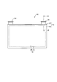
- FIG. 2 shows a schematic configuration of the battery 10 of this embodiment.
- the battery 10 according to the present embodiment has a power generation element 15 housed in a battery case 13 formed by joining a case body 11 and a lid member 12.
- the battery case 13 is a flat rectangular metal case that is thin in the depth direction in the figure.
- the case main body 11 has a box shape with only one upper surface opened in the figure, and the opening portion is sealed with a lid member 12.
- the power generation element 15 of the battery 10 according to the present embodiment includes an electrode body 16 in which a strip-shaped electrode plate and a separator are overlapped and wound flatly, and a non-aqueous electrolyte solution 17.
- the battery 10 has a positive terminal portion 21 and a negative terminal portion 22. The positive electrode terminal portion 21 and the negative electrode terminal portion 22 protrude from the lid member 12 of the battery case 13 to the outside of the battery 10.
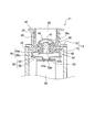
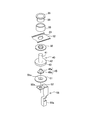
- FIG. 3 shows an enlarged view of a part of the AA cross section of FIG. Moreover, each component before the assembly of the positive electrode terminal portion 21 is shown in an exploded perspective view of FIG.
- a through hole 23 is formed in the lid member 12 at the position of the positive electrode terminal portion 21.
- the positive electrode terminal portion 21 includes a pole column terminal 30 and a caulking terminal 40. Further, the positive electrode terminal portion 21 includes a sealing member 32 for insulating the lid member 12 and the crimping terminal 40 and an insulating member 33 for insulating the lid member 12 and the pole column terminal 30.
- 3 is the same direction as FIG. 2, and the upper side in FIG. 3 is the outside of the battery 10, and the lower side in FIG. 3 is the inside of the battery 10.
- the pole terminal 30 is a substantially bottomed cylindrical metal member having a cylindrical portion 34, a flange portion 35, and a bottom surface portion 36.
- a female screw 34 a is formed on the inner peripheral surface of the cylindrical portion 34.
- a through hole 36 a is formed in the bottom surface portion 36 of the pole terminal 30.
- the flange portion 35 is an annular seat surface that is formed so as to spread from the tip end portion (end portion far from the bottom surface portion 36) of the cylindrical portion 34 toward the outer side in the radial direction.
- the upper surface of the collar portion 35 is flat.
- the seal member 32 is a substantially ring-shaped member disposed along the inner peripheral surface of the through hole 23 of the lid member 12 as shown in FIG. A seal member 32 seals between the caulking terminal 40 and the lid member 12. Therefore, the inside of the battery case 13 is sealed.
- As the material of the seal member 32 rubber or a resin material having elasticity is suitable.
- the insulating member 33 is disposed between the lid member 12 and the pole column terminal 30 to insulate them.
- the insulating member 33 is formed of an insulating resin material or the like.
- the caulking terminal 40 has a protruding portion 41, a base surface portion 42, and a side surface portion 43 formed continuously.
- the protruding portion 41 is a hollow protruding portion having a cylindrical shape with a closed tip before being attached.
- the base surface portion 42 of the caulking terminal 40 is an annular flat plate-shaped portion that extends from the base of the protruding portion 41 toward the outer peripheral direction.
- the side surface portion 43 is a cylindrical portion formed by extending from the outer peripheral end of the base surface portion 42 in the direction opposite to the protruding portion 41.
- the protruding portion 41 shown in FIG. 4 penetrates the through hole 23 of the lid member 12 from the inner side to the outer side of the battery 10, and the inner side of the cylindrical portion 34 of the pole terminal 30. It is inserted into the space.
- the tip portion of the protrusion 41 that is, the portion located in the internal space of the cylindrical portion 34 is in a state of being caulked and deformed. That is, the tip end portion of the protrusion 41 is crushed from the original state in the height direction, and is wider than the original state in the radial direction.
- the leading end portion of the protruding portion 41 projects outward in the radial direction from the through hole 36 a of the pole terminal 30.
- the caulking terminal 40 sandwiches the lid member 12 and the pole column terminal 30 by the protruding portion 41 and the base surface portion 42, thereby connecting the pole column terminal 30, the seal member 32, and the insulating member 33. It is fixed to the lid member 12.
- the caulking terminal 40 is made of metal and has conductivity.
- the protruding portion 41 may be formed slightly thinner than other portions so as to have flexibility.
- the shaft member 45 is disposed inside the protruding portion 41. As shown in FIG. 3, the shaft member 45 has a columnar top portion 45a and a flange portion 45b formed at an end portion thereof. At least the tip portion of the top portion 45 a is fitted into the protruding portion 41 of the crimping terminal 40. The flange portion 45 b is in contact with the base surface portion 42 of the crimping terminal 40 and is disposed inside the space surrounded by the side surface portion 43.
- the shaft member 45 of this embodiment is preferably made of metal such as aluminum, SUS, or plated steel.
- a CID 50 is attached to an end portion of the side surface portion 43 far from the protruding portion 41.
- the CID 50 of this embodiment has a reversing plate 51 and a connecting plate 52.
- the reversing plate 51 has a reversing portion 51a that is reversed and deformed by receiving pressure.
- the battery 10 in a state where the CID is not operating, and the state of the battery 10 in a normal state.
- the reversing plate 51 of this embodiment is formed of a substantially disc-shaped metal plate.
- the peripheral edge 51b of the reversing plate 51 is fixed to the end of the side face 43 of the crimping terminal 40 by welding over the entire circumference.
- a secretly sealed space surrounded by the reversing plate 51 and the caulking terminal 40 is formed. Therefore, the internal pressure of this space is hardly affected by the internal pressure of the battery 10, and even if the battery 10 is used, it hardly changes from the time of manufacturing the battery 10.
- a reversing portion 51a is formed at the center of the reversing plate 51 so as to protrude from the peripheral portion 51b toward the inside of the battery 10 (downward in the figure).
- Inversion part 51a of this form is a truncated cone shape.
- the side part 43 of the crimping terminal 40 is provided at a height that does not prevent the inversion of the inversion part 51a. Accordingly, a space having a dimension in the height direction that allows the reversal of the reversing portion 51a is formed inside the side surface portion 43. That is, the reversing part 51 a can be reversed without being pushed back by the base surface part 42 or the shaft member 45 of the crimping terminal 40.
- connection plate 52 is a portion responsible for connection between the reversing portion 51a and the electrode plate in a state where the reversing plate 51 is not reversed.
- the connection plate 52 of the present embodiment is a metal member that is formed continuously and integrally with the internal terminal 55.
- a connection portion 55 a drawn at the lower part of the internal terminal 55 is a portion connected to the positive electrode plate inside the battery 10.
- the connection plate 52 is formed at the end of the internal terminal 55 on the side far from the connection portion 55a.
- connection plate 52 of this embodiment is formed with a round hole 52a that follows the outer shape of the reversing part 51a.
- the reversing portion 51 a of the reversing plate 51 is attached by fitting the bottom surface of the convex side into the round hole 52 a of the connecting plate 52.
- the outer surface of the reversing part 51a and the periphery of the round hole 52a may be lightly fixed, for example, by spot welding or the like, or may be simply pressed and contacted.
- the positive electrode plate of the electrode body 16 is connected to the connection portion 55 a of the internal terminal 55.
- the reversing portion 51 a of the reversing plate 51 is in contact with the edge of the round hole 52 a of the connecting plate 52.
- the reversing plate 51 is welded to the caulking terminal 40 at the peripheral edge portion 51 b, and the caulking terminal 40 is pressed against the pole column terminal 30 at the protruding portion 41.
- the positive electrode plate is electrically connected to the polar column terminal 30 through the internal terminal 55, the reversing plate 51, and the crimping terminal 40. Accordingly, the pole terminal 30 of the battery 10 of this embodiment functions as a positive external terminal.
- the reversing portion 51a of the reversing plate 51 is reversed.
- conduction between the reversing plate 51 and the connecting plate 52 is interrupted. That is, the current path is interrupted between the positive plate and the pole terminal 30.
- the battery 10 thus configured can no longer be charged / discharged via the pole terminal 30.
- the negative terminal portion 22 is not provided with a CID.
- the pole terminal of the negative electrode terminal portion 22 always functions as an external terminal of the negative electrode.
- a plurality of the batteries 10 are arranged and connected by a bus bar 61.
- the positive electrode terminal portion 21 of the first battery 10 and the negative electrode terminal portion 22 of the second battery 10 are arranged adjacent to each other, and the bus bar 61 is arranged so as to contact the flange portions 35 of both pole column terminals 30. It is placed.
- FIG. 10 A cross-sectional view of the positive electrode terminal portion 21 of the battery stack 100 is shown in FIG.
- screws 62 are screwed into the cylindrical portions 34 of the pole column terminals 30 through the holes of the bus bar 61. Therefore, the positive electrode plate of the battery 10 is connected to the bus bar 61 and the screw 62 via the pole column terminal 30, and further connected to the negative electrode terminal portion 22 of the other battery 10 by the bus bar 61. Moreover, the negative electrode terminal part 22 of this battery 10 is further connected to the positive electrode terminal part 21 of another battery by another bus bar.
- the plurality of batteries 10 are connected in series with each other.
- the CID 50 when the internal pressure of the battery 10 rises to a certain level due to some factor, the CID 50 is activated.
- the internal pressure during normal use (SOC 0 to 100%) is 0.15 MPa or less.
- the operating pressure of CID 50 in the battery 10 of this embodiment is in the range of 0.35 to 0.75 MPa. This corresponds to a SOC of 130 to 160%.
- the SOC of the battery 10 of this embodiment corresponds to a voltage of 3V for SOC 0% and a voltage of 4.1V for SOC 100%.
- the internal pressure at which the safety valve of the battery 10 of this embodiment opens is set to about 1.0 MPa.
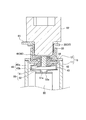
- the reversing portion 51a of the reversing plate 51 is reversed in the positive terminal portion 21 of the battery 10 as shown in FIG. 7, and the connection between the reversing plate 51 and the connecting plate 52 is cut off. As a result, the current path is interrupted between the internal terminal 55 and the bus bar 61. Accordingly, the battery stack 100 is no longer charged.
- This state can be recognized by a controller or the like that controls the battery stack 100. Since the controller usually monitors the status of each battery 10, it is possible to grasp which battery 10 in the battery stack 100 has operated the CID 50.
- the battery stack 100 cannot be used any more.
- the CID 50 is activated, the battery 10 that has not reached the opening of the safety valve is overcharged and maintains a high internal pressure. Therefore, it is not preferable to vibrate the battery stack 100 in this state vigorously or to disassemble it as it is.
- a processing method is provided that can discharge the battery 10 in which the CID 50 is operated without disassembling the battery stack 100. This process is performed after the battery stack 100 including the battery 10 in which the CID 50 is operated is removed from the vehicle or the like.
- the operator who performs this process first determines which of the battery stacks 100 the battery 10 in which the CID 50 is activated. Usually, this determination can be made based on the monitoring result of the controller. Or it is good also as performing from the external appearance about the battery 10 in which the battery case 13 is inflated and the safety valve is not opened. Even if this process is performed on the battery 10 in which the CID 50 is not operating, there is no problem.
- the battery 10 in which the CID 50 is operated is referred to as an operating battery 10.
- the worker removes the screw 62 of the positive terminal portion 21 of the operating battery 10.
- the screw 62 is exposed to the outside from the restraining band 102 of the battery stack 100 and can be easily removed.
- the positive terminal portion 21 becomes as shown in FIG. Even in this state, the inside of the operating battery 10 is sealed, so that no gas is blown out.
- another battery 10 is connected to the bus bar 61 adjacent to the operating battery 10.
- the negative electrode side connection portion 66 of the resistance element adapter 65 is attached to the negative electrode terminal portion 22 of the working battery 10.
- the resistance element adapter 65 has a negative electrode side connection portion 66, a resistor 67, and a positive electrode side connection portion 68.
- the resistance element adapter 65 is connected between the positive electrode and the negative electrode of the operating battery 10 and discharges the operating battery 10 through an appropriate resistance.
- the negative electrode side connection portion 66 may be one that removes the screw 62 and fits into the pole terminal 30, or may be one that is connected to the screw 62 without removing the screw 62.
- the resistor 67 is suitable for the battery 10 of this embodiment with a resistance of about 0.5 to 1.0 ⁇ .
- the operator screws the positive electrode side connection portion 68 of the resistance element adapter 65 into the pole column terminal 30 of the positive electrode terminal portion 21 of the working battery 10.
- the positive electrode side connecting portion 68 has a convex portion 68a at the center of its lower end surface.
- the convex portion 68 a comes into contact with the central portion of the protruding portion 41 of the crimping terminal 40 inside the positive electrode terminal portion 21.
- the operator screws the positive side connection portion 68 further into the depth against the internal pressure of the operating battery 10.
- the projecting portion 41 is deformed so as to be recessed toward the inside of the operating battery 10, and the top portion 45a of the shaft member 45 is pushed down by the recessed portion.
- the protruding portion 41 of the caulking terminal 40 is a portion for caulking and is relatively flexible, so that it is easy to deform it.
- the shaft member 45 is movable because it only has the top portion 45a fitted into the protruding portion 41 and incorporated therein. As a result, the end of the shaft member 45 on the battery inner side is pressed against the reversing portion 51a of the reversing reversing plate 51, and pushes the reversing portion 51a back toward the inside of the battery 10. And the inversion part 51a of the inversion board 51 is reversed in the reverse direction to the time of an operation
- the reversal plate 51 and the connection plate 52 become conductive again.
- the positive electrode side connection portion 68 of the attached resistance element adapter 65 is connected to the crimping terminal 40 or the pole column terminal 30. Accordingly, the operating battery 10 is in a state in which the resistance element adapter 65 is connected between the bipolar terminals, and is discharged through the resistor 67. As a result, the overcharged state of the operating battery 10 is eliminated. Thereafter, the battery stack 100 can be disassembled relatively safely.
- the shaft member 45 of this form has the collar part 45b, the area pressed against the inversion part 51a is large. Therefore, there is a high possibility that the reversing part 51a can be pushed back regardless of the shape of the reversing part 51a. Further, the flange 45b prevents the shaft member 45 from protruding to the outside of the battery 10. Moreover, since the shaft member 45 of this embodiment has conductivity, even if the reversing portion 51a is damaged, it can be re-conducted through the shaft member 45.
- This processing makes it possible to dispose and recycle the operating battery 10.
- the operator removes the resistance element adapter 65.
- the resistance element adapter 65 is reusable. If the resistance value of the resistor 67 is too large, it takes too much time for discharging, which is not preferable. Also, if the resistance value of the resistor 67 is too small, the current value immediately after re-conduction becomes large, which is not preferable.
- the shaft member 45 is disposed inside the protruding portion 41 of the caulking terminal 40. Therefore, when the shaft member 45 is pushed down, the battery 10 in which the CID 50 is activated.
- the reversing part 51a of the reversing plate 51 can be reversed again.
- the resistance element adapter 65 is used, the shaft member 45 can be pushed down by the positive electrode side connection portion 68 via the crimping terminal 40. Further, the battery 10 can be discharged via the resistor 67 by connecting the resistance element adapter 65 to the positive terminal portion 21 and the negative terminal portion 22. Therefore, the battery 10 can be safely and easily disposed even after the CID 50 is activated.
- the shaft member is not limited to being made of metal, but may be made of an insulating resin having durability and heat resistance. Even if the shaft member is insulative, a current path is secured if the reversing part is reversed again.
- the flange portion of the shaft member is not necessarily required, and the shaft member may be simply a rod-shaped member. Or it is good also as a shaft member which formed the edge part in the side which contacts a inversion part in the shape which follows the shape of an inversion part.
- the configuration of the CID is not limited to the above, but can be applied to any type that is generally used.
- a part of the connection plate may be broken instead of detaching the contact portion between the inversion part and the connection plate.
- the connecting plate as shown in FIG. 10, a member having a weakened portion 52b that is easily broken around the round hole 52a is used.
- the fragile portion 52b is broken along with the reversal of the reversing portion 51a.
- rupture location moves with the inversion part 51a, and leaves
- it is preferable that the reversing portion 51a and the round hole 52a are firmly fixed by welding or heat welding.
- connection plate without a hole.
- the convex end of the reversing part may be arranged in contact with the surface of the connecting plate.
- the screw 62 is in contact with the protruding portion 41 and the tip of the protruding portion 41 is flat.
- the screw 62 and the protruding portion 41 do not necessarily have to be in contact with each other.
- the inverted reversal part appears to be in contact with the shaft member, but there may be a gap between them.
- the shaft member seems to be in contact with a portion around the reversing portion of the reversing plate, but it is not essential to push the shaft member down to this position. The shaft member should just be pushed down to the position which reverses an inversion part again.
- the shape of the reversing part is not limited to the truncated cone, and may be a hemisphere, for example.
- the CID is provided in the positive terminal portion, but may be provided in the negative terminal portion.
- the positive electrode terminal made of aluminum is more appropriate than the negative electrode terminal made of copper.
- the resistance value of the resistance element adapter, the operating pressure of the CID, etc. are only examples, and are not limited to the above.
Landscapes
- Chemical & Material Sciences (AREA)
- Chemical Kinetics & Catalysis (AREA)
- Electrochemistry (AREA)
- General Chemical & Material Sciences (AREA)
- Engineering & Computer Science (AREA)
- Manufacturing & Machinery (AREA)
- Connection Of Batteries Or Terminals (AREA)
- Sealing Battery Cases Or Jackets (AREA)
Abstract
Priority Applications (5)
| Application Number | Priority Date | Filing Date | Title |
|---|---|---|---|
| CN201180071879.3A CN103620825B (zh) | 2011-07-27 | 2011-07-27 | 密闭型电池 |
| US14/115,776 US8828598B2 (en) | 2011-07-27 | 2011-07-27 | Sealed-type cell |
| JP2011549781A JP5344048B2 (ja) | 2011-07-27 | 2011-07-27 | 密閉型電池 |
| DE112011105182.4T DE112011105182B4 (de) | 2011-07-27 | 2011-07-27 | Abgedichtete Zelle |
| PCT/JP2011/067096 WO2013014762A1 (fr) | 2011-07-27 | 2011-07-27 | Cellule de type étanche |
Applications Claiming Priority (1)
| Application Number | Priority Date | Filing Date | Title |
|---|---|---|---|
| PCT/JP2011/067096 WO2013014762A1 (fr) | 2011-07-27 | 2011-07-27 | Cellule de type étanche |
Publications (1)
| Publication Number | Publication Date |
|---|---|
| WO2013014762A1 true WO2013014762A1 (fr) | 2013-01-31 |
Family
ID=47600651
Family Applications (1)
| Application Number | Title | Priority Date | Filing Date |
|---|---|---|---|
| PCT/JP2011/067096 Ceased WO2013014762A1 (fr) | 2011-07-27 | 2011-07-27 | Cellule de type étanche |
Country Status (5)
| Country | Link |
|---|---|
| US (1) | US8828598B2 (fr) |
| JP (1) | JP5344048B2 (fr) |
| CN (1) | CN103620825B (fr) |
| DE (1) | DE112011105182B4 (fr) |
| WO (1) | WO2013014762A1 (fr) |
Cited By (5)
| Publication number | Priority date | Publication date | Assignee | Title |
|---|---|---|---|---|
| WO2015097785A1 (fr) * | 2013-12-25 | 2015-07-02 | 日立オートモティブシステムズ株式会社 | Batterie secondaire rectangulaire |
| JP2015162426A (ja) * | 2014-02-28 | 2015-09-07 | 株式会社豊田自動織機 | 蓄電装置およびその蓄電装置の放電方法 |
| CN114614216A (zh) * | 2016-11-15 | 2022-06-10 | 宁德时代新能源科技股份有限公司 | 二次电池及电池模组 |
| WO2024189837A1 (fr) * | 2023-03-15 | 2024-09-19 | 株式会社 東芝 | Batterie |
| WO2025213674A1 (fr) * | 2024-04-10 | 2025-10-16 | 宁德时代新能源科技股份有限公司 | Cellule de batterie, batterie et dispositif électrique |
Families Citing this family (6)
| Publication number | Priority date | Publication date | Assignee | Title |
|---|---|---|---|---|
| JP6185175B2 (ja) * | 2014-07-24 | 2017-08-23 | 日立オートモティブシステムズ株式会社 | 二次電池 |
| KR101704162B1 (ko) | 2015-01-20 | 2017-02-07 | 현대자동차주식회사 | 과충전 안전성이 향상된 파우치 전지 |
| JP6597130B2 (ja) * | 2015-09-29 | 2019-10-30 | 三洋電機株式会社 | 角形二次電池 |
| KR102260830B1 (ko) * | 2016-11-08 | 2021-06-03 | 삼성에스디아이 주식회사 | 이차 전지 팩 |
| CN108232052B (zh) * | 2016-12-09 | 2020-12-11 | 宁德时代新能源科技股份有限公司 | 二次电池 |
| KR20250116186A (ko) | 2017-03-30 | 2025-07-31 | 도날드슨 컴파니, 인코포레이티드 | 릴리프 밸브를 갖는 통기구 |
Citations (4)
| Publication number | Priority date | Publication date | Assignee | Title |
|---|---|---|---|---|
| JPH0864197A (ja) * | 1994-06-17 | 1996-03-08 | Wako Denshi Kk | 二次電池の安全装置 |
| JPH10334883A (ja) * | 1997-06-04 | 1998-12-18 | Mitsubishi Cable Ind Ltd | 密閉型電池の安全構造 |
| JP2011018645A (ja) * | 2009-07-09 | 2011-01-27 | Sb Limotive Co Ltd | 二次電池 |
| JP2011181409A (ja) * | 2010-03-02 | 2011-09-15 | Honda Motor Co Ltd | 電池および電池モジュール |
Family Cites Families (8)
| Publication number | Priority date | Publication date | Assignee | Title |
|---|---|---|---|---|
| US4455356A (en) * | 1983-04-04 | 1984-06-19 | Barrett Jr James H | Bellows boot for secondary battery terminals |
| EP0739047A3 (fr) * | 1995-04-21 | 1999-04-07 | Wako Electronics Co., Ltd. | Dispositif de sécurité pour une batterie secondaire |
| JP3575735B2 (ja) * | 1997-05-16 | 2004-10-13 | Necトーキン栃木株式会社 | 非水系の再充電可能なリチウム電池 |
| KR100861166B1 (ko) * | 2002-02-13 | 2008-09-30 | 마츠시타 덴끼 산교 가부시키가이샤 | 전지 팩의 제조방법 |
| JP4715114B2 (ja) * | 2004-06-17 | 2011-07-06 | トヨタ自動車株式会社 | 電池ケース蓋用パッキン、電池ケース蓋の製造方法、電池の製造方法 |
| CN101304078B (zh) * | 2007-05-09 | 2012-05-23 | 深圳市比克电池有限公司 | 一种防爆电池 |
| JP5490406B2 (ja) * | 2008-12-27 | 2014-05-14 | 三洋電機株式会社 | 車両用の電源装置 |
| JP5741201B2 (ja) | 2011-05-11 | 2015-07-01 | トヨタ自動車株式会社 | 密閉型電池と組電池および密閉型電池の製造方法 |
-
2011
- 2011-07-27 CN CN201180071879.3A patent/CN103620825B/zh active Active
- 2011-07-27 WO PCT/JP2011/067096 patent/WO2013014762A1/fr not_active Ceased
- 2011-07-27 DE DE112011105182.4T patent/DE112011105182B4/de active Active
- 2011-07-27 JP JP2011549781A patent/JP5344048B2/ja active Active
- 2011-07-27 US US14/115,776 patent/US8828598B2/en active Active
Patent Citations (4)
| Publication number | Priority date | Publication date | Assignee | Title |
|---|---|---|---|---|
| JPH0864197A (ja) * | 1994-06-17 | 1996-03-08 | Wako Denshi Kk | 二次電池の安全装置 |
| JPH10334883A (ja) * | 1997-06-04 | 1998-12-18 | Mitsubishi Cable Ind Ltd | 密閉型電池の安全構造 |
| JP2011018645A (ja) * | 2009-07-09 | 2011-01-27 | Sb Limotive Co Ltd | 二次電池 |
| JP2011181409A (ja) * | 2010-03-02 | 2011-09-15 | Honda Motor Co Ltd | 電池および電池モジュール |
Cited By (8)
| Publication number | Priority date | Publication date | Assignee | Title |
|---|---|---|---|---|
| WO2015097785A1 (fr) * | 2013-12-25 | 2015-07-02 | 日立オートモティブシステムズ株式会社 | Batterie secondaire rectangulaire |
| JPWO2015097785A1 (ja) * | 2013-12-25 | 2017-03-23 | 日立オートモティブシステムズ株式会社 | 角形二次電池 |
| US10224535B2 (en) | 2013-12-25 | 2019-03-05 | Hitachi Automotive Systems, Ltd. | Rectangular secondary battery |
| JP2015162426A (ja) * | 2014-02-28 | 2015-09-07 | 株式会社豊田自動織機 | 蓄電装置およびその蓄電装置の放電方法 |
| CN114614216A (zh) * | 2016-11-15 | 2022-06-10 | 宁德时代新能源科技股份有限公司 | 二次电池及电池模组 |
| CN114614216B (zh) * | 2016-11-15 | 2024-04-02 | 宁德时代新能源科技股份有限公司 | 二次电池及电池模组 |
| WO2024189837A1 (fr) * | 2023-03-15 | 2024-09-19 | 株式会社 東芝 | Batterie |
| WO2025213674A1 (fr) * | 2024-04-10 | 2025-10-16 | 宁德时代新能源科技股份有限公司 | Cellule de batterie, batterie et dispositif électrique |
Also Published As
| Publication number | Publication date |
|---|---|
| US8828598B2 (en) | 2014-09-09 |
| JPWO2013014762A1 (ja) | 2015-02-23 |
| JP5344048B2 (ja) | 2013-11-20 |
| US20140141296A1 (en) | 2014-05-22 |
| CN103620825B (zh) | 2015-12-02 |
| DE112011105182B4 (de) | 2017-11-23 |
| CN103620825A (zh) | 2014-03-05 |
| DE112011105182T5 (de) | 2014-01-30 |
Similar Documents
| Publication | Publication Date | Title |
|---|---|---|
| JP5344048B2 (ja) | 密閉型電池 | |
| JP4238228B2 (ja) | キャップ組立体及びこれを備えた二次電池 | |
| KR101627626B1 (ko) | 이차 전지 | |
| US6063518A (en) | Sealed electrochemical cell equipped with a circuit-breaking terminal | |
| KR101916964B1 (ko) | 이차 전지 | |
| JP6380420B2 (ja) | 二次電池および組電池 | |
| KR20110017820A (ko) | 이차 전지 | |
| KR101678727B1 (ko) | 캡 어셈블리 및 이를 포함하는 원형전지 | |
| KR20180005455A (ko) | 캡 조립체 및 이를 이용한 이차 전지 | |
| JP5673195B2 (ja) | 電池 | |
| KR19990027311A (ko) | 각형전지의 켑 조립체 | |
| US7745024B2 (en) | Sealed accumulator equipped with a safety device | |
| WO2011118359A1 (fr) | Batterie hermétique | |
| KR20190049205A (ko) | 전류차단부재 및 캡 조립체 | |
| JP2000113912A (ja) | 電池の電路遮断機構 | |
| WO2015079672A1 (fr) | Batterie cylindrique | |
| KR100238937B1 (ko) | 박형전지 | |
| KR102351247B1 (ko) | 이차전지 | |
| JPH10334883A (ja) | 密閉型電池の安全構造 | |
| JP3639414B2 (ja) | 密閉型電池 | |
| JPH10162798A (ja) | 密閉型電池の安全構造 | |
| KR20060027282A (ko) | 원통형 리튬 이차 전지 | |
| JPH09199105A (ja) | 2次電池用防爆封口板 | |
| KR20060061079A (ko) | 원통형 리튬 이차 전지 | |
| KR102423894B1 (ko) | 이차 전지 |
Legal Events
| Date | Code | Title | Description |
|---|---|---|---|
| ENP | Entry into the national phase |
Ref document number: 2011549781 Country of ref document: JP Kind code of ref document: A |
|
| 121 | Ep: the epo has been informed by wipo that ep was designated in this application |
Ref document number: 11870058 Country of ref document: EP Kind code of ref document: A1 |
|
| WWE | Wipo information: entry into national phase |
Ref document number: 14115776 Country of ref document: US |
|
| WWE | Wipo information: entry into national phase |
Ref document number: 112011105182 Country of ref document: DE Ref document number: 1120111051824 Country of ref document: DE |
|
| 122 | Ep: pct application non-entry in european phase |
Ref document number: 11870058 Country of ref document: EP Kind code of ref document: A1 |