WO2013015042A1 - Machine à découper - Google Patents
Machine à découper Download PDFInfo
- Publication number
- WO2013015042A1 WO2013015042A1 PCT/JP2012/065589 JP2012065589W WO2013015042A1 WO 2013015042 A1 WO2013015042 A1 WO 2013015042A1 JP 2012065589 W JP2012065589 W JP 2012065589W WO 2013015042 A1 WO2013015042 A1 WO 2013015042A1
- Authority
- WO
- WIPO (PCT)
- Prior art keywords
- guides
- workpiece
- disk
- shaped tool
- cutting machine
- Prior art date
- Legal status (The legal status is an assumption and is not a legal conclusion. Google has not performed a legal analysis and makes no representation as to the accuracy of the status listed.)
- Ceased
Links
Images







Classifications
-
- B—PERFORMING OPERATIONS; TRANSPORTING
- B23—MACHINE TOOLS; METAL-WORKING NOT OTHERWISE PROVIDED FOR
- B23D—PLANING; SLOTTING; SHEARING; BROACHING; SAWING; FILING; SCRAPING; LIKE OPERATIONS FOR WORKING METAL BY REMOVING MATERIAL, NOT OTHERWISE PROVIDED FOR
- B23D47/00—Sawing machines or sawing devices working with circular saw blades, characterised only by constructional features of particular parts
- B23D47/005—Vibration-damping
Definitions
- the present invention relates to a cutting machine that rotates a disk-shaped tool and cuts a workpiece with the disk-shaped tool.
- the cutting machine described in Japanese Patent Application Laid-Open No. 2004-338081 is a circular saw, a saw head that rotatably holds a disk-shaped tool, and a pair of guides that are provided on the saw head and face both surfaces of the disk-shaped tool.
- a guide having a predetermined shape is selected according to the diameter of the disk-shaped tool, and the guide is set so that the tip end portion of the guide and the outer peripheral edge of the disk-shaped tool are in the vicinity.
- the guide has a guide body provided on the saw head, a holder provided on the guide body so as to be tiltable, and a contact member that is attached to the holder and faces the disk-shaped tool. The angle of the holder with respect to the guide body is fixed before cutting so that the outer peripheral edge of the tool is in the vicinity.
- the deflection of the outer peripheral edge of the disc-shaped tool having a relatively large deflection is regulated by a pair of guides. The As a result, the workpiece can be accurately cut at a right angle.
- the present invention is a cutting machine that rotates a disk-shaped tool and cuts a workpiece with the disk-shaped tool.
- the cutting machine has a disk-shaped tool, a saw head, two pairs of guides, and a variable device.
- the disk-shaped tool has two sides.
- the saw head holds the disk-shaped tool rotatably.
- Two pairs of guides are provided on the saw head, and each pair of guides faces two surfaces of the disk-shaped tool.
- the variable device varies the distance between the two pairs of guides so that the workpiece passes between the two pairs of guides when the object is cut by the disk-shaped tool.
- the workpiece is cut while the disk-shaped tool rotates during cutting, and the workpiece passes between the two pairs of guides.
- the two pairs of guides restrict deflection (grinding) in the axial direction of the disk-shaped tool at both ends of the cutting arc of the workpiece. Since the distance between the two pairs of guides is variable, the two pairs of guides can be made variable according to the shape of the workpiece. Therefore, when the work passes between the two pairs of guides, the distance between the two pairs of guides can be increased so that the work passes between the two pairs of guides.
- the distance between the two pairs of guides is fixed from the beginning so that the workpiece passes between the two pairs of guides. Therefore, the distance of the guide is set sufficiently large according to the maximum diameter of the workpiece. Therefore, compared with the conventional cutting machine, the present invention can reduce the distance between the two pairs of guides.
- the distance between the cutting position and the guide can be shortened by reducing the distance between the two pairs of guides. Therefore, it is possible to suppress the axial deflection of the disk-shaped tool, in particular, the axial deflection of the disk-shaped tool between the two pairs of guides, which are regions for cutting the workpiece. Thereby, the cut surface of the workpiece can be cut accurately and smoothly at a predetermined angle by the disk-shaped tool.
- FIG. 7 is a cross-sectional view taken along line VII-VII in FIG. 2. It is a diagram which shows the relationship between the distance between upper and lower guides, and rigidity. It is a front view of the guide concerning the cutting machine of another form, a disk-shaped tool, and a workpiece
- FIG. 10 is a front view of the guide, the disk-shaped tool, and the workpiece according to the cutting machine in FIG. 9 when the workpiece is started to be cut.
- FIG. 10 is a front view of the guide, the disk-shaped tool, and the workpiece according to the cutting machine in FIG. 9 when the workpiece is further cut than in FIG. 10.
- FIG. 12 is a front view of the guide, the disk-shaped tool, and the workpiece according to the cutting machine in FIG. 9 when the workpiece is further cut than in FIG. 11.
- FIG. 10 is a front view of the guide, the disk-shaped tool, and the workpiece according to the cutting machine of FIG. 9 when the workpiece has been cut.
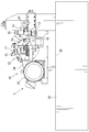
- the cutting machine 1 is a circular saw and includes a base 21 and a saw head 10.
- the saw head 10 is movably attached to the base 21 by rails 26 provided on the base 21.
- the saw head 10 has a head body 22 and a motor 25.
- the motor 25 is connected to the drive shaft 11 of the head main body 22 by a belt 24 and a pulley so that force can be transmitted.
- the head body 22 has a drive shaft 11, a back cover 16, and a front cover 17 as shown in FIGS.
- a disk-shaped tool (saw blade) 2 is mounted on the drive shaft 11.
- the drive shaft 11 is rotated by power from the motor 25, and the disk-shaped tool 2 rotates around the drive shaft 11.
- the disk-shaped tool 2 has a disk shape as shown in FIGS. 2 and 3, and has a base metal 2a in the center area and a cutting area 2b in the outer peripheral area.
- a plurality of blades made of a hard material such as cemented carbide or diamond are attached to the cutting region 2b.
- the disk-shaped tool 2 is a cutting grindstone, diamond abrasive grains, cemented carbide grains, etc. are bonded to the cutting area 2b.
- the disk-shaped tool 2 is preferably thin. Since the disk-shaped tool 2 is thin, the amount of chips generated during cutting is reduced. Further, since the disk-like tool 2 is thin, cutting resistance at the time of cutting is reduced, and energy required at the time of cutting is reduced. However, since the disk-shaped tool 2 is thin, the rigidity in the thickness direction of the disk-shaped tool 2 is reduced, and the disk-shaped tool 2 is easily bent in the axial direction when cutting. On the other hand, the saw head 10 is provided with a plurality of guides 3 and 4 that suppress the deflection in the thickness direction (axial direction) of the disk-shaped tool 2.
- the saw head 10 has a back cover 16 and a front cover 17 as shown in FIG.
- the back cover 16 covers the disk-shaped tool 2 from the back side.
- the guide 3 b is attached to the lower region of the back cover 16 via the attachment member 6.
- a guide 4b is movably attached to the upper region of the back cover 16.
- the front cover 17 is rotatably connected at one end to the back cover 16 as shown in FIG.
- the front cover 17 rotates to move to a closed position that covers the front side of the disk-shaped tool 2 and an open position that opens the front side of the disk-shaped tool 2.
- a guide 3 a is attached to the lower region of the front cover 17 via the attachment member 6.
- a guide 4 a is movably attached to the upper region of the front cover 17.
- variable device 1 a that makes the distance between the guides 3 and 4 variable.
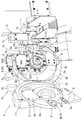
- the variable device 1 a includes a holding mechanism 5 that holds the guide 4 so as to be movable with respect to the saw head 10, and a moving mechanism 1 b that moves the guide 4 according to the shape of the workpiece 20 when cutting.
- the holding mechanism 5 includes an arm 5a, a rail 5b, and a connecting member 5c as shown in FIGS.
- the arm 5a is plate-shaped and extends in an arc shape.
- the rail 5b is formed with a hole extending in an arc shape, and the arm 5a is movably inserted into the hole.
- the rail 5b is attached to the front cover 17 and the back cover 16, and holds the arm 5a so as to be movable concentrically with the rotation of the disk-like tool 2.
- the rail 5 b includes a back portion 5 b 1 that supports the arm 5 a from the back side, a front portion 5 b 2 that supports the arm 5 a from the front side, and an arc-shaped lower portion that supports the arm 5 a from below. 5b3 and an arcuate upper portion 5b4 that covers the arm 5a from above.
- a connecting member 5c is attached to the base end of the arm 5a as shown in FIG.
- the connecting member 5c extends from the arm 5a outward in the radial direction of the disk-shaped tool 2.
- the connecting members 5c provided on the front cover 17 side and the back cover 16 side are integrally connected by an attachment when the front cover 17 is set to the closed position. As a result, the two arms 5 a move together with respect to the saw head 10.
- the gap adjusting plate 9 and the guide 4 are attached to the tip of the arm 5a as shown in FIG.
- the gap adjusting plate 9 and the guide 4 are attached to the surface of the arm 5a on the disk-like tool 2 side.
- the thickness of the gap adjusting plate 9 is determined by the size of the gap between the guide 4 and the disk-shaped tool 2.
- the guides 3 a, 3 b, 4 a, 4 b are plate-shaped as shown in FIGS. 3 and 4 and have a guide surface facing the front surface or the back surface of the base metal 2 a of the disk-shaped tool 2. A small gap is formed between the guides 3a, 3b, 4a, 4b and the disk-shaped tool 2.
- the pair of guides 3a and 3b are provided at corresponding heights and face each other, and the disk-shaped tool 2 is installed between the guides 3a and 3b.
- the pair of guides 3 a and 3 b are installed below the workpiece 20, and the tips of the guides 3 a and 3 b are set in the vicinity of the cutting area 2 b of the disk-shaped tool 2.
- the pair of guides 4a and 4b are attached to the respective arms 5a at opposing positions as shown in FIGS. Therefore, the pair of guides 4a and 4b move together with the arm 5a and always have a facing relationship.
- a disk-shaped tool 2 is installed between the pair of guides 4a and 4b.
- the pair of guides 4a and 4b are located above the other pair of guides 3a and 3b.
- the pair of guides 4a and 4b are positioned at the same height as the workpiece 20 before cutting the workpiece 20, and are moved upward by the moving mechanism 1b at the time of cutting. As a result, the distance between the upper and lower guides 3 and 4 changes.
- the moving mechanism 1b has an urging member 8 and a sliding member 7 as shown in FIG.
- the urging body 8 has a cylinder that uses air pressure, and is provided on the back side of the back cover 16.
- the biasing body 8 is connected to a connecting member 5c provided on the back cover 16, and always biases the connecting member 5c clockwise. As a result, the arm 5 a is urged clockwise by the urging force of the urging body, and the upper guide 4 is urged toward the lower guide 3.
- the sliding member 7 is made of resin and is attached to the arm 5a attached to the back cover 16 as shown in FIGS.
- the sliding member 7 is L-shaped and integrally includes a lower side portion 7a and a front end portion 7b.
- the lower side portion 7a is attached to the lower edge of the tip portion of the arm 5a and protrudes downward from the guide 4b.
- the front end 7b is attached to the front edge of the tip of the arm 5a and projects forward (in the direction of the workpiece 20) from the guide 4b.
- the guide 3 is attached to the attachment member 6 with bolts 18 as shown in FIG.
- a hole is formed in the bolt 18, and a communication hole communicating with the hole of the bolt 18 is formed in the mounting member 6. Air, oil, or both air and oil are supplied to the communication hole of the mounting member 6 in a mist state. Air or oil or the like is blown out from the guide 3 toward the disk-shaped tool 2 through the communication hole and the hole of the bolt 18. As a result, the frictional resistance generated when the disk-shaped tool 2 and the guide 3 come into contact with each other is reduced.
- the guide 4 is attached to the arm 5a by a bolt 18 as shown in FIGS.
- a communication hole communicating with the hole of the bolt 18 is formed in the arm 5a. Air, oil, or both air and oil are supplied to the communication hole of the arm 5a. Air or oil is blown out from the guide 4 toward the disk-shaped tool 2 through the communication hole and the hole of the bolt 18. Thereby, the frictional resistance generated when the disk-shaped tool 2 and the guide 4 come into contact with each other is reduced.
- the base 21 is provided with a vise apparatus 1c for holding the workpiece 20 as shown in FIG.
- the vice apparatus 1 c includes a lower jaw 12, an upper jaw 15, a fixed jaw 13, and a movable jaw 14.
- the lower jaw 12 is fixed to the base 21 and supports the workpiece 20 from below.
- the upper jaw 15 is provided so as to be movable in the vertical direction with respect to the base 21 and pushes the workpiece 20 toward the lower jaw 12.
- the fixed jaw 13 is fixed to the base 21 and supports the workpiece 20 from one side direction.
- the movable jaw 14 is provided so as to be movable in the horizontal direction with respect to the base 21, and pushes the workpiece 20 toward the fixed jaw 13.
- the movable jaw 14 is formed with a slit 14a and an inclined surface 14b.
- the disk-shaped tool 2 is inserted into the slit 14 a and allows the disk-shaped tool 2 to reach the workpiece 20.
- the inclined surface 14 b is formed on the upper end surface of the movable jaw 14 and faces upward and toward the sliding member 7.
- the work 20 is long as shown in FIG. 4, and is a round bar, a pipe, a plate shape, or the like.
- the workpiece 20 is formed from, for example, metal (iron or steel, non-ferrous metal, etc.), resin, or the like.
- the cutting machine 1 includes a feeding device 19 for feeding the workpiece 20 in the longitudinal direction, a releasing device (not shown) for moving the upper jaw 15 and the movable jaw 14, and a control device (not shown) for controlling the feeding device 19 and the releasing device. (Omitted).
- control device After the control device cuts the small piece from the work 20, the control device controls the release device to separate the upper jaw 15 and the movable jaw 14 from the work 20, and sends the work 20 by a predetermined length by the feed device 19 to control the release device.
- the upper jaw 15 and the movable jaw 14 are pressed against the workpiece 20. Thereby, the cutting machine 1 can cut
- the workpiece 20 When cutting the workpiece 20 by the cutting machine 1, the workpiece 20 is set in the vice apparatus 1c as shown in FIG.
- the disk-shaped tool 2 is set on the drive shaft 11, the front cover 17 is closed, and the pair of connecting members 5c are connected.
- the disk-shaped tool 2 is rotated, and the saw head 10 is moved toward the workpiece 20 by the feeding device 23.
- the sliding member 7 hits the inclined surface 14b of the movable jaw 14, and moves upward along the inclined surface 14b.
- the disk-shaped tool 2 hits the workpiece 20 and gradually cuts the workpiece 20.
- the distance between the upper and lower guides 3 and 4 is relatively small.
- the sliding member 7 hits the outer peripheral surface of the work 20 and moves upward along the outer peripheral surface of the work 20.
- the arm 5a moves against the urging force of the urging body 8 of FIG. 3, and the upper guide 4 moves upward.
- the upper guide 4 moves along the outer shape of the workpiece 20 while maintaining a predetermined distance from the outer surface of the workpiece 20. Therefore, the guide 4 moves from the outer peripheral surface of the workpiece 20 at a substantially predetermined distance without hitting the workpiece 20.
- the distance between the upper and lower guides 3 and 4 gradually increases during cutting as shown in FIGS. 5 and 6 and allows the workpiece 20 to enter between the upper and lower guides 3 and 4.
- the disk-shaped tool 2 cuts the workpiece 20 when the cutting region 2 b penetrates the workpiece 20.
- the disk-shaped tool 2 can swing in the axial direction by breaking the balance between the front side and the back side of the cutting force due to wear or the like.
- the base metal 2 a hits the guides 3 and 4, and the wobbling of the disk-shaped tool 2 in the axial direction is restricted by the guides 3 and 4.
- the control device controls the feeding device 23 to return the saw head 10 to its original position.
- the arm 5a is moved by the biasing body 8, and the upper guide 4 is moved toward the lower guide 3.
- the control device controls the release device and the feeding device 19 so that the workpiece 20 moves in the longitudinal direction, and the workpiece 20 is held again by the vice device 1c.
- the workpiece 20 is cut in the same manner as described above, and a plurality of small pieces are cut from the workpiece 20.
- the small piece of the workpiece 20 is used as a material for forming a forged product, for example.
- the upper guide 4 moved upward, and the distance between the upper and lower guides 3, 4 moved between 60 mm and 98 mm.
- the cut surface of the workpiece 20 was measured.
- the bending of the cut surface of the workpiece 20 was 0.057 mm.
- the workpiece 20 was cut while the distance between the guides 3 and 4 was maintained at 100 mm.
- the curvature of the cut surface of the workpiece 20 in the comparative experiment was 0.094 mm. Therefore, it was found that the cut surface of the workpiece 20 can be cut smoothly by making the distance between the upper and lower guides 3 and 4 variable.
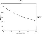
- FIG. 8 shows the experimental results and shows the relationship between the rigidity of the disk-shaped tool 2 and the distance between the upper and lower guides 3 and 4.
- the distance between the upper and lower guides 3 and 4 is set to a predetermined distance
- a force is applied to the disc-shaped tool 2 toward the guides 3 and 4
- the disc-shaped tool 2 is positioned between the guide 3 and the guide 4.
- the axial direction (thickness direction) rigidity force for deforming 1 mm
- the guide when the guide is fixed as in the prior art, for example, when the upper and lower guides are fixed, it is necessary to set the distance between the upper and lower guides to be at least the distance that the workpiece 20 can pass through. Moreover, it is necessary to set the distance between the upper and lower guides to be larger than the diameter of the workpiece 20 in consideration of variations in the diameter of the workpiece 20. For this reason, in the cutting machine for fixing the guide, the rigidity of the disk-shaped tool 2 is lowered, it is not easy to make the cutting surface of the workpiece 20 a predetermined angle (usually a right angle), and the cutting surface can be formed smoothly. Not easy.
- the cutting machine 1 includes the disk-shaped tool 2, the saw head 10, the two pairs of guides 3 and 4, and the variable device 1a as shown in FIGS.
- the disk-shaped tool 2 has two surfaces.
- the saw head 10 holds the disk-shaped tool 2 rotatably.
- Two pairs of guides 3, 4 are provided on the saw head 10, and each pair of guides 3, 4 faces two surfaces of the disk-shaped tool 2.
- the variable device 1 a varies the distance between the two pairs of guides 3 and 4 so that the workpiece 20 passes between the two pairs of guides 3 and 4 when the workpiece 20 is cut by the disk-shaped tool 2.
- the workpiece 20 is cut while the disk-like tool 2 is rotating at the time of cutting, and the workpiece 20 passes between the two pairs of guides 3 and 4.
- the two pairs of guides 3 and 4 restrict the deflection (grinding) in the axial direction of the disk-shaped tool 2 on both sides (up and down) of the workpiece 20. Further, since the distance between the two pairs of guides 3 and 4 is variable, the two pairs of guides 3 and 4 can be made variable according to the shape of the workpiece 20. Therefore, when the workpiece 20 passes between the two pairs of guides 3, 4, the distance between the two pairs of guides 3, 4 can be increased so that the workpiece 20 passes between the two pairs of guides 3, 4.
- the distance between the two pairs of guides is fixed from the beginning so that the workpiece 20 passes between the two pairs of guides. Therefore, the distance of the guide is set sufficiently large according to the maximum diameter of the workpiece 20. Therefore, the present embodiment can reduce the distance between the two pairs of guides 3 and 4 as compared with the conventional cutting machine. By reducing the distance between the two pairs of guides 3 and 4, the distance between the cutting position and the guides 3 and 4 can be shortened. Therefore, it is possible to suppress the axial deflection of the disk-shaped tool 2, particularly the axial deflection of the disk-shaped tool between two pairs of guides, which are regions where the workpiece 20 is cut. Thereby, the cut surface of the workpiece can be cut accurately and smoothly at a predetermined angle by the disk-shaped tool.
- the variable device 1a further includes a holding mechanism 5 and a moving mechanism 1b as shown in FIG.
- the holding mechanism 5 holds the pair of guides 4 so as to be movable with respect to the saw head 10.
- the moving mechanism 1b moves the pair of guides 4 according to the shape of the workpiece 20 cut by the disk-like tool 2. Accordingly, the workpiece 20 passes between the two pairs of guides 3 and 4 during cutting, and the distance between the two pairs of guides 3 and 4 changes according to the shape of the workpiece 20.
- the two pairs of guides 3 and 4 can be positioned relatively close to the workpiece 20 at the time of cutting.
- the moving mechanism 1b further includes an urging body 8 and a sliding member 7 as shown in FIG.
- the urging body 8 urges the pair of guides 4 in a direction that reduces the distance between the two pairs of guides 3 and 4.
- the sliding member 7 slides in contact with a workpiece 20 provided on the pair of guides 4 and cut by the disk-shaped tool 2. Therefore, the distance between the two pairs of guides 3 and 4 is minimized by the biasing body 8 before cutting.
- the sliding member 7 comes into contact with the workpiece 20.
- the guide 4 moves together with the sliding member 7 against the urging force of the urging body 8, and the distance between the two pairs of guides 3 and 4 increases. Therefore, the distance between the two pairs of guides 3 and 4 changes according to the shape of the workpiece 20.
- the holding mechanism 5 further has an arm 5a and a rail 5b as shown in FIG.
- a pair of guides 4 is attached to the arm 5a.
- the rail 5b holds the arm 5a so that the arm 5a moves in a concentric circle at the center of the disk-shaped tool 2. Therefore, the guide 4 is moved concentrically with the disk-like tool 2 by the holding mechanism 5. Therefore, the guide 4 is set so as to move along the cutting area 2b. Thereby, the guide 4 can always suppress the axial deflection of the disk-shaped tool 2 at a position in the vicinity of the cutting region 2b. Thus, the axial deflection of the disk-shaped tool 2 can be effectively suppressed.
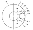
- the cutting machines shown in FIGS. 9 to 13 may be used instead of the cutting machines shown in FIGS. 9 to 13 includes a pair of guides 30, another pair of guides 31, and a variable device (not shown).
- Each pair of guides 30 and 31 is provided so as to be movable with respect to the saw head 10.
- the variable device has a holding mechanism and a moving mechanism.
- the holding mechanism holds the guides 30 and 31 so as to be movable with respect to the saw head 10.
- the moving mechanism moves the guides 30 and 31 according to the shape of the workpiece 20 when cutting.
- first projecting portions 30a and 31a are formed with first projecting portions 30a and 31a, second projecting portions 30b and 31b, and recessed portions 30c and 31c.
- the first projecting portions 30 a and 31 a project from one end of the guides 30 and 31 on the cutting area 2 b side of the disc-shaped tool 2 toward the other guides 30 and 31.
- the second projecting portions 30 b and 31 b project from one end portion of the guides 30 and 31 on the center side of the disk-shaped tool 2 toward the other guides 30 and 31.
- the recesses 30 c and 31 c have a shape corresponding to the outer shape of the workpiece 20.
- the recesses 30 c and 31 c have a radius of curvature larger than the shape of the workpiece 20, for example, larger than the radius of the workpiece 20. Thereby, the workpiece
- work 20 is accommodated between the recessed parts 30c and 31c.
- the cutting amount of the workpiece 20 and the deflection amount of the disk-shaped tool 2 when the workpiece 20 was cut by the cutting machine shown in FIGS. 9 to 13 were analyzed, and indicated by each point 34 in FIG.
- the amount of deflection shown in FIG. 15 is the maximum amount of deflection between the guides 30 and 31 at the tip of the disk-shaped tool 2.
- the cutting machine shown in FIG. 14 was assumed.
- the amount of cutting of the cutting machine shown in FIG. 14 and the amount of deflection of the disk-shaped tool 2 were analyzed and indicated by points 35 in FIG.
- Each pair of guides 32 and 33 is attached to the saw head 10 so as not to move.
- the distance between the guides 32 and 33 is fixed to be larger than the assumed maximum diameter of the workpiece 20. Therefore, the distance between the guides 32 and 33 is always kept constant during cutting.
- the deflection amount at the same cutting amount is smaller at each point 34 in the cutting machine shown in FIG. 9 than in each point 35 in the cutting machine shown in FIG. 14.
- the point 34 and the point 35 at the first time point and the last time point of the cut amount are both zero.
- the peak value of the deflection amount is smaller at each point 34 than at each point 35.
- the time for which the peak value lasts is shorter at each point 34 than at each point 35.
- the rate of increase in the amount of deflection at the beginning of cutting is smaller at each point 34 than at each point 35, and the difference is large.
- the grinding amount is obtained from the integration of the cutting amount and the deflection amount, and is represented by a region in FIG. Therefore, the amount of grinding is smaller than the area represented by each point 35 in the area represented by each point 34, and is about a quarter. That is, the amount of bending in the cutting machine of FIG. 9 is smaller than the amount of bending in the cutting machine of FIG. It can be seen from FIG. 15 that the main factor is the difference in the rate of increase in the amount of deflection at the beginning of cutting.
- the variable device 1a may have a holding mechanism 5 for holding the upper guide 4 and a moving mechanism 1b for moving the upper guide 4 as shown in FIG.
- the variable device 1a may have a holding mechanism that movably holds the lower guide 3 in place of or in addition to the holding mechanism 5 and the moving mechanism 1b, and a moving mechanism that moves the lower guide 3.
- the moving mechanism 1 b may have an urging body 8 and a sliding member 7. Instead, the moving mechanism 1b may include a drive mechanism that moves the arm 5a and a control device that controls the drive mechanism.
- the control device controls the drive mechanism on the basis of workpiece information input in advance or a detection signal from a sensor that measures the shape of the workpiece. Thereby, the guide 4 can be moved according to the shape of the workpiece 20 together with the arm 5a.
- the moving mechanism 1b may move the guide 4 following the outer shape of the workpiece 20.
- the guide 4 may be moved along the outline shape of the workpiece 20.
- the guide 4 may be moved slowly following the shape of the workpiece 20.
- the holding mechanism 5 may hold the guide 4 so as to be movable concentrically with the disk-like tool 2. Alternatively, the holding mechanism 5 may hold the guide 4 so as to be movable on a curve or straight line that is concentric with the disk-like tool 2.
- the urging body 8 may have a cylinder that generates an urging force by air pressure.
- the biasing body 8 may be a spring or rubber that generates a biasing force by an elastic force.
- the biasing body 8 may be a gas spring that generates a biasing force by gas pressure.
- the disk-shaped tool 2 may have a cutting area 2b on the outer periphery. Or the disk-shaped tool 2 may have a cutting area
- the cutting machine 1 may have two pairs of guides 3 and 4. Alternatively, the cutting machine 1 may have three or more pairs of guides.
Landscapes
- Engineering & Computer Science (AREA)
- Mechanical Engineering (AREA)
- Sawing (AREA)
Abstract
Une machine à découper (1) possède un outil discoïde (2), une tête (10) de scie, deux paires de guides (3, 4) et un dispositif variable (1a). L'outil discoïde (2) possède deux surfaces. La tête (10) de scie maintient l'outil discoïde (2) rotatif. Les deux paires de guides (3, 4) sont disposées dans la tête (10) de scie et chaque paire de guides (3, 4) est tournée vers les deux surfaces de l'outil discoïde (2). Le dispositif variable (1a) modifie les distances pour les deux paires de guides (3, 4) de sorte qu'une pièce (20) passe entre les deux paires de guides (3, 4) lorsque la pièce (20) est découpée par l'outil discoïde (2).
Priority Applications (4)
| Application Number | Priority Date | Filing Date | Title |
|---|---|---|---|
| EP12817349.9A EP2737968B1 (fr) | 2011-07-27 | 2012-06-19 | Machine à découper |
| JP2013525625A JP5996536B2 (ja) | 2011-07-27 | 2012-06-19 | 切断機 |
| KR1020147004060A KR101879608B1 (ko) | 2011-07-27 | 2012-06-19 | 절단기 |
| CN201280037061.4A CN103796782B (zh) | 2011-07-27 | 2012-06-19 | 切割机 |
Applications Claiming Priority (2)
| Application Number | Priority Date | Filing Date | Title |
|---|---|---|---|
| JP2011164117 | 2011-07-27 | ||
| JP2011-164117 | 2011-07-27 |
Publications (1)
| Publication Number | Publication Date |
|---|---|
| WO2013015042A1 true WO2013015042A1 (fr) | 2013-01-31 |
Family
ID=47600901
Family Applications (1)
| Application Number | Title | Priority Date | Filing Date |
|---|---|---|---|
| PCT/JP2012/065589 Ceased WO2013015042A1 (fr) | 2011-07-27 | 2012-06-19 | Machine à découper |
Country Status (6)
| Country | Link |
|---|---|
| EP (1) | EP2737968B1 (fr) |
| JP (2) | JP5996536B2 (fr) |
| KR (1) | KR101879608B1 (fr) |
| CN (1) | CN103796782B (fr) |
| TW (1) | TWI538755B (fr) |
| WO (1) | WO2013015042A1 (fr) |
Cited By (1)
| Publication number | Priority date | Publication date | Assignee | Title |
|---|---|---|---|---|
| JP2017104929A (ja) * | 2015-12-09 | 2017-06-15 | 株式会社アマダホールディングス | 丸鋸盤 |
Citations (4)
| Publication number | Priority date | Publication date | Assignee | Title |
|---|---|---|---|---|
| JPH02239901A (ja) * | 1989-03-14 | 1990-09-21 | Fuji Kogyo Kk | 丸鋸盤における振れ止装置 |
| JPH0340019U (fr) * | 1989-08-25 | 1991-04-17 | ||
| JPH07227714A (ja) * | 1994-02-17 | 1995-08-29 | Kitagawa Denki:Kk | 丸鋸切断機 |
| JP2004338081A (ja) | 2003-04-08 | 2004-12-02 | Keuro Besitz Gmbh & Co Edv Dienstleistungs Kg | 丸のこ盤 |
Family Cites Families (7)
| Publication number | Priority date | Publication date | Assignee | Title |
|---|---|---|---|---|
| US2941451A (en) * | 1956-05-02 | 1960-06-21 | Hughes Aircraft Co | Cutter support |
| DE2447147C3 (de) * | 1974-10-03 | 1986-08-21 | Jägers, Leopold, 5350 Euskirchen | Maschine zum Kaltsägen von Stahlplatten mit horizontalem Vorschub |
| JPH03208519A (ja) * | 1990-01-11 | 1991-09-11 | Amada Co Ltd | 帯鋸盤における鋸刃ガイドの自動位置設定方法およびその装置 |
| US5398578A (en) * | 1992-11-12 | 1995-03-21 | Andersen; Jens H. | Breakaway guide |
| JPH08155731A (ja) * | 1994-12-08 | 1996-06-18 | Amada Co Ltd | 帯鋸盤における移動側鋸刃ガイドアームの自動位置決め方法およびその装置 |
| CN2810841Y (zh) * | 2005-04-11 | 2006-08-30 | 长沙中联重工科技发展股份有限公司 | 硬质合金圆锯床 |
| CN201744734U (zh) * | 2010-05-27 | 2011-02-16 | 张家港和升数控机床制造有限公司 | 一种锯切装置 |
-
2012
- 2012-06-19 KR KR1020147004060A patent/KR101879608B1/ko active Active
- 2012-06-19 EP EP12817349.9A patent/EP2737968B1/fr active Active
- 2012-06-19 JP JP2013525625A patent/JP5996536B2/ja active Active
- 2012-06-19 CN CN201280037061.4A patent/CN103796782B/zh active Active
- 2012-06-19 WO PCT/JP2012/065589 patent/WO2013015042A1/fr not_active Ceased
- 2012-06-26 TW TW101122741A patent/TWI538755B/zh active
-
2016
- 2016-07-12 JP JP2016137283A patent/JP6169760B2/ja active Active
Patent Citations (4)
| Publication number | Priority date | Publication date | Assignee | Title |
|---|---|---|---|---|
| JPH02239901A (ja) * | 1989-03-14 | 1990-09-21 | Fuji Kogyo Kk | 丸鋸盤における振れ止装置 |
| JPH0340019U (fr) * | 1989-08-25 | 1991-04-17 | ||
| JPH07227714A (ja) * | 1994-02-17 | 1995-08-29 | Kitagawa Denki:Kk | 丸鋸切断機 |
| JP2004338081A (ja) | 2003-04-08 | 2004-12-02 | Keuro Besitz Gmbh & Co Edv Dienstleistungs Kg | 丸のこ盤 |
Non-Patent Citations (1)
| Title |
|---|
| See also references of EP2737968A4 * |
Cited By (3)
| Publication number | Priority date | Publication date | Assignee | Title |
|---|---|---|---|---|
| JP2017104929A (ja) * | 2015-12-09 | 2017-06-15 | 株式会社アマダホールディングス | 丸鋸盤 |
| WO2017098979A1 (fr) * | 2015-12-09 | 2017-06-15 | 株式会社アマダホールディングス | Machine à scier circulaire dans laquelle l'oscillation de la lame de scie circulaire peut être supprimée |
| US10875107B2 (en) | 2015-12-09 | 2020-12-29 | Amada Holdings Co., Ltd. | Circular saw machine capable of suppressing runout of circular saw blade |
Also Published As
| Publication number | Publication date |
|---|---|
| JP5996536B2 (ja) | 2016-09-21 |
| JPWO2013015042A1 (ja) | 2015-02-23 |
| EP2737968A4 (fr) | 2015-03-11 |
| CN103796782A (zh) | 2014-05-14 |
| TW201318739A (zh) | 2013-05-16 |
| JP2016193489A (ja) | 2016-11-17 |
| EP2737968A1 (fr) | 2014-06-04 |
| KR20140060291A (ko) | 2014-05-19 |
| EP2737968B1 (fr) | 2020-03-25 |
| CN103796782B (zh) | 2016-01-06 |
| JP6169760B2 (ja) | 2017-07-26 |
| TWI538755B (zh) | 2016-06-21 |
| KR101879608B1 (ko) | 2018-07-19 |
Similar Documents
| Publication | Publication Date | Title |
|---|---|---|
| JP7372057B2 (ja) | マイターカットするための鋸盤 | |
| CN101980813B (zh) | 工具机、尤其是下置式台式圆盘锯 | |
| WO2011118299A1 (fr) | Outil de traitement par frottement et procédé et équipement de traitement par frottement utilisant celui-ci | |
| JP5685276B2 (ja) | 鋸身のバックテーパ加工装置 | |
| JP6169760B2 (ja) | 丸鋸盤および該丸鋸盤による切断方法 | |
| JP3177599U (ja) | 円形部材の端部研削加工装置 | |
| CN102958646A (zh) | 测量夹具、线锯、工件附装方法 | |
| CN107553226B (zh) | 一种仿形铣刀刃磨装置 | |
| TW201134632A (en) | Riving knife device for a saw unit | |
| TW201444644A (zh) | 切削機及其控制方法 | |
| JP4369279B2 (ja) | 丸のこ盤 | |
| CN105081820B (zh) | 一种配置快捷压紧和松开夹具的机床 | |
| CN113305655A (zh) | 一种金刚石刀具加工装置 | |
| CN219151747U (zh) | 一种锯床进给反馈装置 | |
| JP4148166B2 (ja) | 接触検出装置 | |
| JPWO2005037509A1 (ja) | ワーク切断装置およびワーク切断方法 | |
| US9527147B2 (en) | Saw blade indexing assembly | |
| JP5433489B2 (ja) | 裁断刃位置調整治具、及び、裁断刃位置調整方法 | |
| KR20030077877A (ko) | 장축의 공작물을 가공하는 장치 및 그 가공방법 | |
| CN223198081U (zh) | 一种仪表车床快速启动同步夹紧装置 | |
| CN209919014U (zh) | 一种研磨机的磨削机构 | |
| JP4454850B2 (ja) | 鋸歯を有する加工物を機械加工するための機械 | |
| CN119703653B (zh) | 一种可倾瓦止推轴承瓦块加工方法及设备 | |
| CN211465026U (zh) | 一种金属切割锯床固定件 | |
| JP2884080B1 (ja) | 多刃研削工具の刃先成形方法および刃先成形装置 |
Legal Events
| Date | Code | Title | Description |
|---|---|---|---|
| 121 | Ep: the epo has been informed by wipo that ep was designated in this application |
Ref document number: 12817349 Country of ref document: EP Kind code of ref document: A1 |
|
| ENP | Entry into the national phase |
Ref document number: 2013525625 Country of ref document: JP Kind code of ref document: A |
|
| NENP | Non-entry into the national phase |
Ref country code: DE |
|
| ENP | Entry into the national phase |
Ref document number: 20147004060 Country of ref document: KR Kind code of ref document: A |