WO2013015235A1 - Unité de notification de statut de batterie, module de barre omnibus, batterie assemblée et système de surveillance de statut de batterie - Google Patents
Unité de notification de statut de batterie, module de barre omnibus, batterie assemblée et système de surveillance de statut de batterie Download PDFInfo
- Publication number
- WO2013015235A1 WO2013015235A1 PCT/JP2012/068559 JP2012068559W WO2013015235A1 WO 2013015235 A1 WO2013015235 A1 WO 2013015235A1 JP 2012068559 W JP2012068559 W JP 2012068559W WO 2013015235 A1 WO2013015235 A1 WO 2013015235A1
- Authority
- WO
- WIPO (PCT)
- Prior art keywords
- battery
- unit
- battery state
- cell
- connector
- Prior art date
- Legal status (The legal status is an assumption and is not a legal conclusion. Google has not performed a legal analysis and makes no representation as to the accuracy of the status listed.)
- Ceased
Links
Images



Classifications
-
- H—ELECTRICITY
- H01—ELECTRIC ELEMENTS
- H01M—PROCESSES OR MEANS, e.g. BATTERIES, FOR THE DIRECT CONVERSION OF CHEMICAL ENERGY INTO ELECTRICAL ENERGY
- H01M10/00—Secondary cells; Manufacture thereof
- H01M10/42—Methods or arrangements for servicing or maintenance of secondary cells or secondary half-cells
- H01M10/48—Accumulators combined with arrangements for measuring, testing or indicating the condition of cells, e.g. the level or density of the electrolyte
- H01M10/482—Accumulators combined with arrangements for measuring, testing or indicating the condition of cells, e.g. the level or density of the electrolyte for several batteries or cells simultaneously or sequentially
-
- H—ELECTRICITY
- H01—ELECTRIC ELEMENTS
- H01M—PROCESSES OR MEANS, e.g. BATTERIES, FOR THE DIRECT CONVERSION OF CHEMICAL ENERGY INTO ELECTRICAL ENERGY
- H01M10/00—Secondary cells; Manufacture thereof
- H01M10/42—Methods or arrangements for servicing or maintenance of secondary cells or secondary half-cells
- H01M10/425—Structural combination with electronic components, e.g. electronic circuits integrated to the outside of the casing
-
- G—PHYSICS
- G01—MEASURING; TESTING
- G01R—MEASURING ELECTRIC VARIABLES; MEASURING MAGNETIC VARIABLES
- G01R31/00—Arrangements for testing electric properties; Arrangements for locating electric faults; Arrangements for electrical testing characterised by what is being tested not provided for elsewhere
- G01R31/36—Arrangements for testing, measuring or monitoring the electrical condition of accumulators or electric batteries, e.g. capacity or state of charge [SoC]
- G01R31/371—Arrangements for testing, measuring or monitoring the electrical condition of accumulators or electric batteries, e.g. capacity or state of charge [SoC] with remote indication, e.g. on external chargers
-
- G—PHYSICS
- G01—MEASURING; TESTING
- G01R—MEASURING ELECTRIC VARIABLES; MEASURING MAGNETIC VARIABLES
- G01R31/00—Arrangements for testing electric properties; Arrangements for locating electric faults; Arrangements for electrical testing characterised by what is being tested not provided for elsewhere
- G01R31/36—Arrangements for testing, measuring or monitoring the electrical condition of accumulators or electric batteries, e.g. capacity or state of charge [SoC]
- G01R31/396—Acquisition or processing of data for testing or for monitoring individual cells or groups of cells within a battery
-
- H—ELECTRICITY
- H01—ELECTRIC ELEMENTS
- H01M—PROCESSES OR MEANS, e.g. BATTERIES, FOR THE DIRECT CONVERSION OF CHEMICAL ENERGY INTO ELECTRICAL ENERGY
- H01M10/00—Secondary cells; Manufacture thereof
- H01M10/42—Methods or arrangements for servicing or maintenance of secondary cells or secondary half-cells
- H01M10/48—Accumulators combined with arrangements for measuring, testing or indicating the condition of cells, e.g. the level or density of the electrolyte
- H01M10/486—Accumulators combined with arrangements for measuring, testing or indicating the condition of cells, e.g. the level or density of the electrolyte for measuring temperature
-
- H—ELECTRICITY
- H01—ELECTRIC ELEMENTS
- H01M—PROCESSES OR MEANS, e.g. BATTERIES, FOR THE DIRECT CONVERSION OF CHEMICAL ENERGY INTO ELECTRICAL ENERGY
- H01M10/00—Secondary cells; Manufacture thereof
- H01M10/42—Methods or arrangements for servicing or maintenance of secondary cells or secondary half-cells
- H01M10/425—Structural combination with electronic components, e.g. electronic circuits integrated to the outside of the casing
- H01M2010/4271—Battery management systems including electronic circuits, e.g. control of current or voltage to keep battery in healthy state, cell balancing
-
- H—ELECTRICITY
- H01—ELECTRIC ELEMENTS
- H01M—PROCESSES OR MEANS, e.g. BATTERIES, FOR THE DIRECT CONVERSION OF CHEMICAL ENERGY INTO ELECTRICAL ENERGY
- H01M10/00—Secondary cells; Manufacture thereof
- H01M10/42—Methods or arrangements for servicing or maintenance of secondary cells or secondary half-cells
- H01M10/425—Structural combination with electronic components, e.g. electronic circuits integrated to the outside of the casing
- H01M2010/4278—Systems for data transfer from batteries, e.g. transfer of battery parameters to a controller, data transferred between battery controller and main controller
-
- H—ELECTRICITY
- H01—ELECTRIC ELEMENTS
- H01M—PROCESSES OR MEANS, e.g. BATTERIES, FOR THE DIRECT CONVERSION OF CHEMICAL ENERGY INTO ELECTRICAL ENERGY
- H01M2220/00—Batteries for particular applications
- H01M2220/20—Batteries in motive systems, e.g. vehicle, ship, plane
-
- Y—GENERAL TAGGING OF NEW TECHNOLOGICAL DEVELOPMENTS; GENERAL TAGGING OF CROSS-SECTIONAL TECHNOLOGIES SPANNING OVER SEVERAL SECTIONS OF THE IPC; TECHNICAL SUBJECTS COVERED BY FORMER USPC CROSS-REFERENCE ART COLLECTIONS [XRACs] AND DIGESTS
- Y02—TECHNOLOGIES OR APPLICATIONS FOR MITIGATION OR ADAPTATION AGAINST CLIMATE CHANGE
- Y02E—REDUCTION OF GREENHOUSE GAS [GHG] EMISSIONS, RELATED TO ENERGY GENERATION, TRANSMISSION OR DISTRIBUTION
- Y02E60/00—Enabling technologies; Technologies with a potential or indirect contribution to GHG emissions mitigation
- Y02E60/10—Energy storage using batteries
Definitions
- the present invention provides, for example, a battery state notification unit used for monitoring a state of an assembled battery mounted in a hybrid vehicle, an electric vehicle, or the like, a bus bar module and an assembled battery having the battery state notification unit, and the battery state notification unit.
- the present invention relates to a battery state monitoring system.
- the HEV includes two types of batteries: a low-voltage battery of about 12 V for starting the engine and operating electric components in the vehicle, and a high-voltage battery for driving the electric motor.
- the high voltage battery described above has a secondary battery such as a nickel metal hydride battery or a lithium battery as a unit cell (that is, a battery cell), and a plurality of unit cells are connected in series to form an assembled battery to obtain a high voltage (for example, , See Patent Document 1).
- the voltage between the electrodes of each unit cell that is, the state of charge (SOC) varies as charging and discharging are repeated.
- SOC state of charge
- the high voltage battery described above generates a large amount of heat by discharging a large current when the electric motor is driven. There is a case. Therefore, it is necessary to monitor the temperature of the high-voltage battery in order to stop the discharge and prevent the abnormal state before it reaches such a high-temperature abnormal state. Further, since the interelectrode voltage also changes as the battery temperature changes, the interelectrode voltage is also corrected by the temperature.
- FIG. 16 shows a high voltage battery system which is a conventional battery state monitoring system.
- This high voltage battery system (indicated by reference numeral 801 in the figure) has a plurality of high voltage batteries 810 as assembled batteries and a battery state monitoring device 850 that monitors the state of the high voltage battery 810.
- the high-voltage battery 810 includes a battery module 820 having a plurality of battery cells 821 arranged in one direction, a bus bar module 830 arranged on the upper surface of the battery module 820, a connector plug 841 and a plurality of electric wires 842.
- a wire harness 840 is provided.
- the bus bar module 830 is provided with a plurality of bus bars 831.
- the plurality of bus bars 831 connect the whole of the plurality of battery cells 821 in series by connecting the positive electrode and the negative electrode of the battery cells 821 adjacent to each other.
- the bus bar module 830 is provided with a plurality of temperature sensor units 832 that output a voltage corresponding to the measured temperature at the center and both ends in the one direction (that is, the arrangement direction of the plurality of battery cells 821). ing.
- each of the plurality of electric wires 842 of the wire harness 840 is connected to a terminal portion (not shown) in the connector plug 841, and the other end of the plurality of wires 842 overlaps the plurality of bus bars 831.
- the plurality of terminal fittings 833 connected to the electrodes and the temperature sensor unit 832 are connected to each other.
- the battery state monitoring device 850 includes, for example, a box-shaped case 851 and a control unit (not shown) configured by a microcomputer housed in the case 851.
- the case 851 is provided with a connector socket (not shown) that fits with the connector plug 841 of the wire harness 840 exposed from the case 851.
- the control unit and the wire harness 840 that is, the terminal fitting 833 and the temperature sensor unit 832 are connected.
- control unit detects the inter-electrode voltage of the plurality of battery cells and the temperature of the battery cell based on the voltage values output from the plurality of terminal fittings 833 and the temperature sensor unit 832, and each high voltage battery 810. Was monitoring whether or not is in a normal state.
- the voltage of the electrode of the battery cell 821 is input to the battery state monitoring device 850 through the wire harness 840, the voltage of the electrode of the battery cell 821 is a high voltage whose potential difference from the reference potential of the vehicle body or the like is several hundred volts.
- the safety / reliability design such as insulation resistance and noise resistance is taken into consideration that such a high voltage and a low voltage for control are mixed. Therefore, there is a problem that it is difficult to electrically design the apparatus and the like.
- the battery state monitoring system 901 connects a battery pack 910 as a plurality of assembled batteries, a battery state monitoring unit 960 that monitors the state of the plurality of battery packs 910, and a plurality of battery packs 910 and a battery state monitoring unit 960. And a wire harness 970.
- the battery pack 910 includes a battery module 920 including a plurality of battery cells 921 arranged in a row, a plurality of bus bars 932, a plurality of terminal fittings 933, a plurality of temperature sensor units 934, and a battery state notification unit 940.
- the battery state notification unit 940 has a cell voltage signal and temperature sensor unit corresponding to the inter-electrode voltage of the battery cell 921 output from the terminal fitting 933 of the battery pack 910. Based on the cell temperature signal corresponding to the voltage output from the 934, battery state information including a digital signal including information indicating the voltage and temperature between the electrodes of the battery cell 921 is generated, and the battery state information is monitored.
- Send to unit 960 Send to unit 960.
- the battery state monitoring unit 960 can monitor the state of the battery pack 910 based on the battery state information transmitted from the battery state notification unit 940 of each battery pack 910. Therefore, the battery state notification unit The number of the plurality of electric wires in the wire harness 970 connecting the 940 and the battery state monitoring unit 960 can be reduced, and the wiring design and wiring work of the wire harness 970 can be easily performed. Further, since the battery state information consisting of a digital signal is transmitted to the battery state monitoring unit 960, the voltage level of the signal to be transmitted can be reduced to a low voltage of about several volts. Electrical design such as safety / reliability design such as safety and noise resistance was made easy.
- the battery state notification unit 940 provided in the battery pack 910 is designed according to the number of the battery cells 921 constituting the battery module 920 of the battery pack 910.
- a plurality of battery packs 910 are mounted on the battery pack 910. Since the number of battery cells 921 may differ from each other depending on the specifications of the vehicle to be used and the restrictions on the arrangement space, the battery state notification unit 940 cannot be diverted between battery packs having different numbers of battery cells 921. For this reason, there is a problem that it is difficult to share the battery state notification unit 940 and the manufacturing cost cannot be reduced.
- the present invention aims to solve such a problem. That is, a battery state notification unit that can be easily diverted between battery packs having different numbers of battery cells, a bus bar module and an assembled battery having the battery state notification unit, and a battery state monitoring system having the battery state notification unit The purpose is to do.
- the invention described in claim 1 outputs a plurality of battery cells obtained by multiplying a predetermined unit number S by an integer n of 2 or more, and an analog signal corresponding to the state of the battery cells.
- a battery state notification unit provided in an assembled battery having a plurality of battery state output means and connected to a battery state monitoring unit for monitoring the state of the assembled battery, and for each of the predetermined unit number S of battery cells
- a plurality of corresponding subunits (that is, n), and the subunit is in a state of the battery cell corresponding to the subunit based on the analog signal output by the battery state output means;
- Information generating means for generating battery state information comprising a digital signal including information indicating the information, and the battery state information generated by the information generating means to the battery state monitoring unit It is battery state notification unit, characterized in that has an information transmission means for signals, a.
- the invention described in claim 2 is the invention described in claim 1, wherein the subunit further includes information relay means for relaying the battery state information transmitted by the other subunit. It is characterized by this.
- the information relay means is provided so that the information connector can be fitted to the first connector and the first connector of the other subunit. 2 connector, and the transmission part which transmits the said battery state information between the said 1st connector and the said 2nd connector, It is characterized by the above-mentioned.
- the invention described in claim 4 is a bus bar module provided in an assembled battery having a plurality of battery cells obtained by multiplying a predetermined unit number by an integer of 2 or more.
- a bus bar module comprising: a plurality of battery state output means for outputting an analog signal corresponding to a state; and the battery state notification unit according to any one of claims 1 to 3. .
- a fifth aspect of the present invention provides a plurality of battery cells obtained by multiplying a predetermined unit number by an integer of 2 or more and a plurality of analog signals corresponding to the state of the battery cells.
- An assembled battery comprising a battery state notification unit according to any one of claims 1 to 3.
- the invention described in claim 6 outputs (a) a plurality of battery cells obtained by multiplying a predetermined unit number by an integer of 2 or more, and an analog signal corresponding to the state of the battery cells.
- a battery state monitoring system comprising: one or more assembled batteries having a plurality of battery state output means; and (b) one battery state monitoring unit that monitors the state of the assembled battery.
- a battery state monitoring system wherein the battery is provided with the battery state notification unit according to any one of claims 1 to 3.
- a plurality of subunits corresponding to a predetermined number of battery cells are provided for a plurality of battery cells included in the assembled battery, and these subunits are battery status output means. Based on the analog signal output by the unit, generates battery state information including a digital signal including information indicating the state of the battery cell corresponding to the subunit, and transmits the battery state information to an external battery state monitoring unit. Therefore, by adding or reducing the number of subunits according to the number of battery cells included in the assembled battery, it can be used between assembled batteries having different numbers of battery cells.
- the battery status notification unit can be used in common by changing the number of units according to the number of battery cells of the assembled battery. , The manufacturing cost can be reduced.
- the subunit since the subunit further includes information relay means for relaying the battery state information transmitted by the other subunit, the plurality of subunits are connected in series to each other.
- the battery status information transmitted by each subunit can be aggregated into one subunit arranged at the end via each subunit, so that only the one subunit is external battery status What is necessary is just to connect with a monitoring unit, and thereby, the connection with the outside becomes simple, and the assemblability of the apparatus and system in which the battery state notification unit is incorporated can be improved.
- the information relay means includes the first connector, the second connector provided so as to be fitted to the first connector of the other subunit, the first connector, and the second connector.
- a transmission unit that transmits battery state information to and from the connector, so that the subunits can be directly connected to each other by fitting the first connector and the second connector between the subunits. Therefore, the assembly of the battery state notification unit can be improved by eliminating the need for a wire harness connecting the subunits.
- the battery cell included in the assembled battery is provided.
- the number of subunits included in the battery status notification unit is the same as the number of battery cells of the assembled battery.
- the battery state notification unit can be used in common, and the manufacturing cost can be reduced.
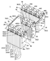
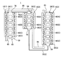
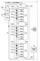
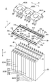
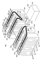
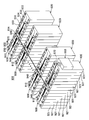
- FIG. 1 It is a perspective view which shows the battery power supply system which is one Embodiment of the battery state monitoring system of this invention. It is a top view of the battery power supply system of FIG. It is a functional block diagram of the battery power supply system of FIG. It is a disassembled perspective view of the battery pack which the battery power supply system of FIG. 1 has.
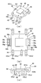
- (A) is a perspective view of the subunit of the battery state notification unit included in the battery pack of FIG. 4,
- (b) is a top view of the subunit of (a), and
- (c) is (a). It is a side view of the subunit.
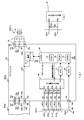
- A) is a functional block diagram of the subunit of FIG.
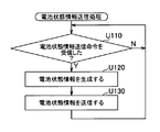
- (b) is a diagram showing a modification of the connection between the terminal leg and the cell voltage input unit in the subunit of (a). . It is a flowchart which shows an example of the battery cell voltage detection process which the microcomputer (CPU) of the subunit of Fig.6 (a) performs. It is a flowchart which shows an example of the battery cell temperature detection process which the microcomputer (CPU) of the subunit of Fig.6 (a) performs. It is a flowchart which shows an example of the battery status information transmission process which the microcomputer (CPU) of the subunit of Fig.6 (a) performs.
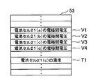
- FIG. 6 It is a figure explaining the voltage storage area
- Battery power system battery pack (assembled battery) 10 Battery pack (assembled battery) 20 battery module 21 battery cell 21c positive electrode 21d negative electrode 22 battery set 30 bus bar module 31 case 32 bus bar (battery state output means) 33 Terminal fitting (battery status output means) 34 Temperature sensor (battery status output means) 36 Lead wire 39 Battery state notification unit 40 Sub unit 42 Unit board 43 Terminal leg portion 45 Cell voltage input portion 47 First ADC portion 48 Second ADC portion 50 Microcomputer 51 CPU (information generating means) 55 Communication module (information transmission means) 58 First connector (information relay means) 59 Second connector (information relay means) 60 Battery State Monitoring Unit 70 Wire Harness 71 Power Line 72 Shared Signal Line 73 Ground Line 423 Relay Wiring Pattern (Transmission Unit, Information Relay Means) S Predetermined number of units V1 to V4 Voltage storage area between electrodes T1 Temperature storage area
- the battery power system of this embodiment is mounted on a hybrid vehicle and supplies power to an electric motor.
- This battery power supply system includes a battery pack that constitutes the high-voltage power supply for driving the electric motor.
- the hybrid vehicle is provided with a low voltage battery that constitutes a low voltage system power supply of about 12 V for starting the engine and operating the electrical components inside the vehicle.
- a battery power supply system (indicated by reference numeral 1 in the figure) includes a battery pack 10 as a plurality of assembled batteries, and a battery state monitoring unit that monitors the states of the plurality of battery packs 10. 60, and a plurality of wire harnesses 70 that connect the plurality of battery packs 10 and the battery state monitoring unit 60.
- the plurality of battery packs 10 are connected so as to form a closed circuit in series with the electric motor M by a power cable 85 capable of energizing a large current.
- three battery packs 10 (battery packs 10 (1) to (3)) are provided.
- (1) to (3) are added to the end of the reference numerals of the respective constituent members.
- the battery pack 10 includes a battery module 20 and a bus bar module 30.
- the battery pack 10 (1) is shown as a representative example, but the other battery packs 10 (2) and (3) are similarly configured.
- the battery module 20 has a plurality of battery cells 21 arranged in a line in one direction (in the direction of arrow X in FIG. 4) and fixed to each other.
- the number of the battery cells 21 is set to a number obtained by multiplying the predetermined unit number S by an integer n of 2 or more.
- An assembly of the battery cells 21 having the predetermined unit number S is used as one battery set 22.
- the predetermined unit number S is set to 4, and the plurality of battery cells 21 in the battery pack 10 (1) are 12 times the predetermined unit number S (battery cells 21 (a) to 21). (L)) is provided.
- the battery cells 21 (a) to (d) constitute a battery set 22 (A)
- the battery cells 21 (e) to (h) constitute a battery set 22 (B).
- the battery cells 21 (i) to (l) constitute the battery set 22 (C).
- a battery unit 21 of a predetermined unit number S constitutes a battery set 22 in the same manner as the battery pack 10 (1).
- the above is an example, and the number of battery packs 10, the number of battery cells 21 in each battery pack 10, the predetermined unit number S, and the like are arbitrary as long as the object of the present invention is not violated.
- Each battery cell 21 has a rectangular parallelepiped battery main body 23 and a pair of cylindrical positive electrodes 25 and negative electrodes 26 made of conductive metal provided so as to protrude from one end and the other end of one surface 24 of the battery main body 23. And. The outer peripheral surfaces of the positive electrode 25 and the negative electrode 26 are threaded. A nut (not shown) is screwed to the positive electrode 25 and the negative electrode 26, and a bus bar 32 and a terminal fitting 33 (to be described later) are fastened and fixed to the positive electrode 25 and the negative electrode 26 by this nut.
- the plurality of battery cells 21 are arranged so that the one surface 24 of the battery body 23 is directed in the same direction (upward in FIG. 4), and the battery bodies 23 of the adjacent battery cells 21 are in contact with each other. Further, the plurality of battery cells 21 are arranged so that the positive electrodes 25 of one battery cell 21 and the negative electrodes 26 of other battery cells 21 adjacent to the one battery cell 21 are alternately adjacent (that is, the arrow X Along the direction, a positive electrode 25, a negative electrode 26, a positive electrode 25, a negative electrode 26,. The plurality of battery cells 21 are fixed to each other by a restraining member (not shown) so as to maintain the arrangement state.
- the battery module 20 is configured in a substantially rectangular parallelepiped shape in which a plurality of battery cells 21 are connected.
- the bus bar module 30 includes a case 31, a plurality of bus bars 32, a plurality of terminal fittings 33, a plurality of temperature sensor units 34, and a battery state notification unit 39.
- the case 31 is formed in a substantially flat plate shape with an insulating synthetic resin or the like.
- the shape of the case 31 in plan view is formed in a rectangular shape that is substantially the same as the shape of the surface of the battery module 20 (hereinafter referred to as “electrode surface 20a”) in which the one surface 24 of each battery cell 21 is continuous.
- electrode surface 20a the shape of the surface of the battery module 20
- a plurality of box portions 31 b opened upward to accommodate a plurality of bus bars 32 and a plurality of terminal fittings 33 described later are formed in the longitudinal direction of the case 31. They are arranged in two rows in the direction (X direction).
- the case 31 is attached to the battery module 20 so that the other surface opposite to the upper surface 31a closely overlaps the electrode surface 20a of the battery module 20. At this time, through holes corresponding to the positive electrode 25 and the negative electrode 26 are provided on the bottom surface of the plurality of box portions 31b so that the positive electrode 25 and the negative electrode 26 on the electrode surface 20a protrude into the box portion 31b. It has been. 1, 2, and 13, the case 31 is omitted for convenience of explanation.
- Each of the plurality of bus bars 32 has a bus bar main body 32a made of a substantially rectangular conductive metal plate, and a pair of bus bar through holes 32b and 32c are provided at both ends of the bus bar main body 32a.
- the plurality of bus bars 32 are provided according to the number of battery cells 21 of the battery module 20 (that is, (number of battery cells 21) ⁇ 1). In the configuration shown in FIG. 4, 11 bus bars 32 are provided.
- the pair of bus bar through holes 32b and 32c are formed so as to overlap with the through holes on the bottom surface of the box portion 31b.
- the positive electrode 25 and the negative electrode 26 of the battery cells 21 adjacent to each other are inserted into the pair of bus bar through holes 32b and 32c, whereby the bus bar 32 connects the battery cells 21 in series.
- the plurality of terminal fittings 33 each have a metal fitting body 33a made of a substantially square conductive metal plate, and a metal fitting through hole 33b is provided at the center of the metal fitting body 33a.
- two terminal fittings 33 are provided.
- One terminal fitting 33 has one end of the case 31 (see FIG. 4) so that the positive electrode 25 of the battery cell 21 (a) disposed at one end of the battery module 20 is inserted into the fitting through hole 33b. It is arranged in a box part 31b provided on the left side.
- the other terminal fitting 33 is inserted into the fitting through-hole 33b through the negative electrode 26 of the battery cell 21 (l) disposed at the other end of the battery module 20 (see FIG. 4). Is disposed in the box portion 31b provided on the right side of the box.
- the plurality of bus bars 32 and the plurality of terminal fittings 33 are connected to a battery state notification unit 39 described later.
- the bus bar 32 and the terminal fitting 33 correspond to battery state output means in the claims.
- the voltage (interelectrode voltage) of the positive electrode 25 and the negative electrode 26 of the battery cell 21 observed (that is, outputted) through the bus bar 32 and the terminal fitting 33 corresponds to the analog signal in the claims.
- Each of the plurality of temperature sensors 34 includes a temperature detection element 34a such as a thermistor element, and a connector 34c connected to the temperature detection element 34a via a lead wire 34b, and according to the temperature measured by the temperature detection element 34a.
- the output voltage is output to the connector 34c.
- the same number of temperature sensors 34 as the number of battery sets 22 are provided corresponding to each battery set 22 in the battery module 20.
- a total of three pieces are provided, one at each longitudinal end portion and longitudinal center portion of the case 31.
- the temperature sensor units 34 (A) to (C) correspond to the battery sets 22 (A) to (C), respectively, and the battery cells 21 included in the battery sets 22 (A) to (C), respectively. They are arranged on (c), (g), (k).
- the temperature detection element 34a of each temperature sensor unit 34 is fitted and disposed in a through-hole provided in the case 31 in accordance with the shape of the temperature detection element 34a so as to contact the electrode surface 20a of the battery module 20.
- the voltage corresponding to the temperature of the electrode surface 20a that is, the battery cell 21 (c), (g), (k)) is output.
- the plurality of temperature sensor units 34 are connected to a battery state notification unit 39 to be described later.
- the temperature sensor unit 34 corresponds to battery state output means in the claims.
- the voltage output from the temperature sensor unit 34 corresponds to an analog signal in the claims. Note that twelve temperature sensor units 34 may be provided so as to correspond to all of the battery cells 21 (a) to (l).
- the battery state notification unit 39 has a plurality of subunits 40 connected in series with each other, and is disposed on the upper surface 31 a of the case 31. In the present embodiment, the same number of subunits 40 as the number of the battery sets 22 are provided corresponding to each battery set 22 in the battery module 20.
- the battery state notification unit 39 (1) is configured by connecting three subunits 40 (subunits 40 (A) to (C)) in series.
- the battery status notification unit 39 (2) is configured by connecting two subunits 40 (subunits 40 (A) and (B)) in series, and the battery status notification unit 39 (3) Four subunits 40 (subunits 40 (A) to (D)) are connected in series.
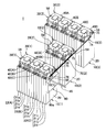
- the subunit 40 has a unit substrate 42 as shown in FIGS. 5 (a) to 5 (c).
- the unit substrate 42 is configured by mounting various electronic components such as a microcomputer 50 (hereinafter also referred to as “ ⁇ COM 50”) on a substrate portion 421 made of a known rectangular printed circuit board (PCB) provided with a wiring pattern. ing.
- ⁇ COM 50 a microcomputer 50
- the ⁇ COM 50 is mounted on one surface (hereinafter referred to as “upper surface 421a”) of the substrate portion 421, and the electronic components other than the ⁇ COM 50 are not shown.
- the unit substrate 42 is provided with a temperature sensor connector 54, a first connector 58, a second connector 59, and a plurality of terminal legs 43.
- the temperature sensor connector 54 is a well-known board-mounting connector, and is disposed on the other surface (hereinafter, referred to as “lower surface 421b”) opposite to the upper surface 421a of the substrate portion 421.
- the temperature sensor connector 54 is electrically connected to the subunit 40 by being connected to the connector 34c of the temperature sensor 34 described above.
- the temperature sensor connection connector 54 is connected to a second ADC 48 section described later through a wiring pattern.
- the first connector 58 is a female connector having a substantially rectangular tube-shaped housing 58a bent into an L-shape and female terminal fittings 58v, 58g, 58s accommodated in the housing 58a.
- a fitting opening 58b is provided at the tip of the housing 58a.
- the base end of the housing 58a is attached to one edge portion of the lower surface 421b of the substrate portion 421, and the fitting opening 58b at the distal end portion of the housing 58a is the upper surface 421a of the substrate portion 421. It is arranged with the side facing.
- the second connector 59 is a male connector having a substantially rectangular tube-shaped housing 59a bent into an L-shape, and male terminal fittings 59v, 59g, 59s accommodated in the housing 59a.
- a fitting opening 59b is provided at the tip of the housing 59a.
- the second connector 59 is attached to the other edge portion of the upper surface 421a of the base plate portion 421 where the proximal end portion of the housing 59a is opposed to the one edge portion, and the fitting opening portion at the distal end portion of the housing 59a.
- 59b is arranged with the lower surface 421b side of the substrate portion 421 facing.
- the female terminal fitting 58v and the male terminal fitting 59v are connected to the power supply wiring pattern (that is, the power supply voltage Vcc (FIG. 6)) of the board portion 421.
- the female terminal fitting 58g and the male terminal fitting 59g are connected to the ground wiring pattern (that is, the ground GND (FIG. 6)) of the board portion 421.
- the female terminal fitting 58s and the male terminal fitting 59s are connected to each other by the relay wiring pattern 423 (FIG. 6) of the board portion 421.
- the relay wiring pattern 423 is connected to a communication module 55 described later.
- the relay wiring pattern 423 corresponds to a transmission unit in the claims, and the first connector 58, the second connector 59, and the relay wiring pattern 423 constitute information relay means in the claims.
- the first connector 58 and the second connector 59 are configured to be fitted to each other.
- the female terminal fitting 58v and the male terminal fitting 59v, the female terminal fitting 58g and the male terminal fitting 59g, the female terminal fitting 58s and the male terminal fitting 59s. Are in contact with each other.
- the power supply wiring pattern between the one subunit 40 and the other subunit 40 is obtained.
- the ground wiring pattern and the relay wiring pattern 423 are electrically connected to each other.
- the first connector 58 of the subunit 40 (B) is connected to the second connector 59 of the subunit 40 (A), and the subunit 40 (B)
- the battery status notification unit 39 (1) Composed.
- the battery state notification units 39 (2) and (3) are similarly configured.
- the harness 70 (2) is connected, and the first connector 58 of the subunit 40 (A) of the battery state notification unit 39 (2) and the second connector 40 (D) of the battery state notification unit 39 (3) are connected.
- the two connectors 59 are connected by a wire harness 70 (3) described later.
- the power supply wiring pattern and the ground wiring pattern of each subunit 40 of the battery state notification units 39 (1) to 39 (3) are electrically connected to each other by the power supply line 71 and the ground line 73 of the wire harness 70.
- the relay wiring pattern 423 and the shared signal line 72 of the wire harness 70 constitute one logical signal line (bus signal line) that connects each subunit 40 via a bus.
- the battery state monitoring unit 60 When the second connector of the subunit 40 (C) of the battery state notification unit 39 (1) and the connector 66 of the battery state monitoring unit 60 are connected by a wire harness 70 (1) described later, the battery state monitoring unit 60, the low-voltage power supply is supplied to the power supply wiring pattern and the ground wiring pattern of each subunit 40 through the power supply line 71 and the ground line 73 of the wire harness 70 (1). Operates with a low-voltage power supply. Further, the battery state monitoring unit 60 and each subunit 40 are bus-connected by the shared signal line 72 of each wire harness 70 and the relay wiring pattern 423 of each subunit 40.
- the terminal leg portion 43 has a substantially L-shaped metal fitting body 44 in which, for example, a conductive sheet metal is punched into a strip shape and its longitudinal central portion is bent at a right angle.
- One end of the metal fitting body 44 is provided with a leg through hole 44a through which the positive electrode 25 or the negative electrode 26 of the battery cell 21 is inserted.
- the other end portion of the metal fitting main body 44 is fixed to the substrate portion 421 by soldering through the substrate portion 421 from the lower surface 421b side.
- the terminal leg portion 43 is connected to a cell voltage input portion 45 described later through a wiring pattern or the like.
- the plurality of terminal leg portions 43 are provided at a pair of edge portions orthogonal to the edge portions of the board portion 421 where the first connector 58 and the second connector 59 are provided, respectively.
- three (terminal leg portions 43 (a), (c), (e)) are provided on one of the pair of edge portions, and two (terminal leg portions 43 (b), (d) are provided on the other. )), A total of five.
- the leg through holes 44 a of the plurality of terminal leg portions 43 are disposed so as to overlap the bus bar through holes 32 b and 32 c of the bus bar 32 or the metal through holes 33 b of the terminal fitting 33.
- each terminal leg 43 is fastened together with the bus bar 32 or the terminal fitting 33. Fixed.
- Each terminal leg 43 is electrically connected to the bus bar 32 or the terminal fitting 33 (that is, the positive electrode 25 and the negative electrode 26 of each battery cell 21).
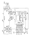
- FIG. 6A shows a functional block diagram of the subunit 40.
- the subunit 40 (A) provided corresponding to the battery set 22 (A) is shown as an example, but the other subunits 40 (B) and (C) are also sub-units.
- the configuration is the same as that of the unit 40 (A).
- the subunit 40 (A) further includes: The cell voltage input unit 45, the first ADC unit 47, the second ADC unit 48, the ⁇ COM 50, and the communication module 55 are provided on the substrate unit 421. Note that the cell voltage input unit 45, the first ADC unit 47, the second ADC unit 48, the ⁇ COM 50, and the communication module 55 may be provided as individual components, or may be housed in one IC package. May be.
- the cell voltage input unit 45 includes a plurality of input terminals PI1 to PI5, one output terminal PO, a switching control terminal C, and a connection switching control signal 1 input to the switching control terminal C in accordance with the input terminals PI1 to PI5.
- a known multiplexer circuit (not shown) that outputs a signal corresponding to the voltage input to PI5 from the output terminal PO.
- the battery module 20 that is, a plurality of battery cells 21 that outputs an inter-electrode voltage (that is, a high voltage analog signal) of about several tens of volts corresponding to the remaining amount of the battery cell 21 is provided.
- the first ADC unit 47 connected to each input terminal PI and operating at a low voltage of about several volts is connected to the output terminal PO. Therefore, the high voltage portion (that is, the high voltage system power source) and the low voltage portion (that is, the low voltage system power source) are separated, and a high voltage analog signal that can be input to the first ADC unit 47 is separated.
- a known flying capacitor circuit (not shown, for example, see JP-A-11-248755, JP-A-2006-337130, etc.) is further included.
- the terminal leg 43 (a) is connected to the input terminal PI1 of the cell voltage input unit 45 via the current limiting resistor R1. That is, the positive electrode 25 of the battery cell 21 (a) is connected to the input terminal PI1. Further, the terminal leg 43 (b) is connected to the input terminal PI2 via the current limiting resistor R2. That is, the negative electrode 26 of the battery cell 21 (a) and the positive electrode 25 of the battery cell 21 (b) are connected to the input terminal PI2. Similarly, the negative electrodes 26 of the battery cells 21 (b) and (c) and the battery cells 21 (c) and (d) are connected to the input terminals PI3 and PI4 through current limiting resistors R3 and R4, respectively. ) Positive electrode 25 is connected. Further, the negative electrode 26 of the battery cell 21 (d) is connected to the input terminal PI5 via the current limiting resistor R5.
- an inter-electrode voltage between the positive electrode 25 and the negative electrode 26 of the battery cell 21 (a) is input between the input terminal PI1 and the input terminal PI2.
- the voltage between the electrodes of the battery cell 21 (b) is input between the input terminal PI2 and the input terminal PI3.
- the battery cells 21 (c), (d) are input to the input terminals PI3 to PI5.
- the interelectrode voltage is input.
- the cell voltage input unit 45 converts the interelectrode voltage of the battery cell 21 input to the input terminal PI into a “cell voltage signal” which is a low voltage analog signal by a flying capacitor circuit, and also connects from the ⁇ COM 50.
- the cell voltage signal corresponding to the battery cell 21 designated by the switching control signal 1 is output from the output terminal PO.
- discharge switches SW1 to SW4 for short-circuiting adjacent input terminals PI are connected to the input terminals PI1 to PI5 of the cell voltage input unit 45, respectively.
- the discharge switch SW1 is provided between the input terminal PI1 and the input terminal PI2
- the discharge switch SW2 is provided between the input terminal PI2 and the input terminal PI3.
- SW3 and SW4 are provided between the input terminals PI3 to PI5.
- the discharge switches SW1 to SW4 are opened and closed independently by a control signal from the ⁇ COM 50.
- the discharge switch SW1 when the discharge switch SW1 is closed, the positive electrode 25 of the battery cell 21 (a), the current limiting resistor R1, the discharge switch SW1, the current limiting resistor R2, and the negative electrode 26 of the battery cell 21 (a).
- a closed circuit is formed in the order of, and the battery cell 21 (a) is discharged. Thereby, the voltage between electrodes of battery cell 21 (a) can be reduced.
- the other discharge switches SW2 to SW4 correspond to the battery cells 21 (b) to (d).
- the discharge cells SW2 to SW4 are closed so that the battery cell 21 (b ) To (d) can be discharged to reduce the voltage between the electrodes.
- the discharge switches SW1 to SW4 are normally opened, and are closed only when the battery cell 21 needs to be discharged.
- the input terminals PI1 to PI5 of the cell voltage input unit 45 are connected to the terminal legs 43 (a) to (e) via the current limiting resistors R1 to R5. ).
- the present invention is not limited to this.
- the terminal legs 43 (a) and (b) are directly connected to the input terminals PI1 and PI2 of the cell voltage input unit 45.
- the discharge switch SW1 and the current limiting resistor R1 connected in series thereto may be provided between the input terminal PI1 and the input terminal PI2.
- the other input terminals PI3 to PI5 are directly connected to the terminal legs 43 (c) to (e), and the discharge switches SW2 to SW4 and the current limiting resistors R2 to R4 connected in series thereto are connected. Is provided between the input terminals PI. By doing so, the number of current limiting resistors becomes four (R1 to R4), and the number of current limiting resistors can be reduced by one. Further, since each terminal leg 43 and each input terminal PI are directly connected, the voltage drop due to the current limiting resistor is eliminated, and the detection accuracy of the voltage between the electrodes of the battery cell 21 can be improved. Even in the closed state (ie, when the battery cell is discharged), the voltage between the electrodes can be detected with high accuracy.
- the first ADC unit 47 is a well-known analog-digital conversion circuit.
- the output terminal PO of the cell voltage input section 45 is connected to the input section of the first ADC section 47, and the ⁇ COM 50 is connected to the output section of the first ADC section 47.
- the first ADC unit 47 quantizes the cell voltage signal to convert the cell voltage signal into a digital value, and converts the cell voltage signal converted into the digital value to the first ADC unit 47. Output to ⁇ COM50.
- the second ADC unit 48 is a well-known analog-digital conversion circuit similar to the first ADC unit 47.
- the temperature sensor connector 54 is connected to the input part of the second ADC unit 48, and the ⁇ COM 50 is connected to the output part of the second ADC unit 48.
- the voltage (ie, analog signal) output from the temperature sensor unit 34 (A) is input through the temperature sensor connector 54 as the “cell temperature signal”
- the second ADC unit 48 quantizes the cell temperature signal.
- the cell temperature signal converted to the digital value is output to the ⁇ COM 50.
- the microcomputer 50 includes a central processing unit (CPU) 51 that performs various processes and controls according to a predetermined program, a ROM 52 that is a read-only memory that stores a processing program for the CPU 51, various information, and the like.
- a RAM 53 that is a readable / writable memory having an area necessary for processing operations of the CPU 51 and an external interface unit (not shown).
- the ROM 52 stores a processing program that causes the CPU 51 to function as various means such as information generation means.
- the CPU 51 functions as the various means by executing the processing program.
- the first ADC unit 47 and the second ADC unit 48 are connected to the external interface unit.
- the external interface unit sends the cell voltage signal and the cell temperature signal input from the first ADC unit 47 and the second ADC unit 48 to the CPU 51.
- a communication module 55 is connected to the external interface unit.
- the communication module 55 is configured to perform communication (LIN communication) using a LIN (Local Interconnect Network) protocol which is a well-known serial multiplex communication protocol.
- the communication module 55 is disposed between the ⁇ COM 50 and the relay wiring pattern 423.
- the communication module 55 is connected to the relay wiring pattern 423 of the other subunit 40 and the shared signal line 72 of the wire harness 70 through the relay wiring pattern 423, the female terminal fitting 58s and the male terminal fitting 59s. . That is, the communication module 55 is logically connected to one signal line (bus signal line) constituted by the relay wiring pattern 423 of each subunit 40 and the shared signal line 72 of the wire harness 70.
- the communication module 55 uses the relay wiring pattern 423 and the shared signal line 72 to perform LIN communication with a battery state monitoring unit 60 (described later) connected to the shared signal line 72 in the same manner.
- the communication module 55 outputs various kinds of information such as commands sent from the battery state monitoring unit 60 to the ⁇ COM 50 through the relay wiring pattern 423 and the shared signal line 72, and various kinds of information such as battery state information sent from the ⁇ COM 50.
- Information is output to the battery state monitoring unit 60 through the relay wiring pattern 423 and the shared signal line 72.
- the communication module 55 corresponds to information transmission means in the claims.
- the subunit 40 (A) that is, the CPU 51 of the ⁇ COM 50
- the battery cell voltage detection process (FIG. 7) the battery cell temperature detection process (FIG. 8), and the battery state information transmission process (FIG. 9) are performed in parallel. Execute.
- CPU51 performs a battery cell voltage detection process (FIG. 7) with a predetermined
- the CPU 51 first switches the connection of the cell voltage input unit 45 so that a cell voltage signal corresponding to the voltage between the electrodes of the first battery cell 21 (a) is output to the first ADC unit 47 (S110).
- the CPU 51 detects the interelectrode voltage of the battery cell 21 (a) based on the cell voltage signal input from the first ADC unit 47 (S120).
- the detected inter-electrode voltage of the battery cell 21 (a) is stored in the battery cell 21 (a) among the inter-electrode voltage storage regions V1 to V4 (shown in FIG. 10) provided for each of the plurality of battery cells 21 on the RAM 53. ) Is stored in the area V1 corresponding to (S130).
- the CPU 51 detects the inter-electrode voltage of the fourth battery cell 21 (d), which is the last battery cell (N in S140), the battery cells 21 (b) to (d) are sequentially applied in the same manner as described above. ), The connection of the cell voltage input unit 45 is switched so that a cell voltage signal corresponding to the interelectrode voltage is output to the first ADC unit 47 (S150), and based on the cell voltage signal input from the first ADC unit 47 The inter-electrode voltage of the battery cells 21 (b) to (d) is detected (S120), and the detected inter-electrode voltage of the battery cells 21 (b) to (d) is stored in the inter-electrode voltage storage area on the RAM 53.
- the CPU 51 executes a battery cell temperature detection process (FIG. 8) at a predetermined cycle.
- the cell temperature signal of the temperature sensor unit 34 (A) is input to the second ADC unit 48. Then, in the second ADC unit 48, the cell temperature signal is quantized and converted into a digital value, and the cell temperature signal converted into the digital value is input to the CPU 51 through the external interface unit.
- the CPU 51 detects the temperature of the battery cell 21 based on the cell temperature signal input from the second ADC unit 48 (T110). Then, the detected temperature of the battery cell 21 is stored in the temperature storage region T1 provided corresponding to the plurality of battery cells 21 (c) on the RAM 53 (T120), and the battery cell temperature detection process is terminated. Each time this battery cell temperature detection process is executed, the temperature of the battery cell 21 stored in the temperature storage region T1 is updated.
- the CPU 51 executes battery state information transmission processing (FIG. 9).
- the CPU 51 waits until a predetermined battery state information transmission command is received from battery state monitoring unit 60 through communication module 55 (N in U110).
- the battery state information transmission command is received (Y in U110)
- the interelectrode voltage of each battery cell 21 is read out from the interelectrode voltage storage areas V1 to V4, and the temperature of the battery cell 21 from the temperature storage area T1.
- Is read, and battery state information including the interelectrode voltage and temperature is generated (U120).
- the battery state information generated here is represented as a digital signal. That is, the CPU 51 corresponds to the information generation means in the claims.
- the generated battery state information is transmitted to the battery state monitoring unit 60 through the communication module 55 (U130). Thereafter, the above process is repeated.
- the CPU 51 executes a battery cell discharge process in parallel with the above processes.
- the battery state monitoring unit 60 has a box-shaped unit case 60a, and a board portion 60b on which various electronic components are mounted is accommodated in the unit case 60a (see FIG. 1). 11).
- the battery state monitoring unit 60 is fixedly attached to the battery module 20 of one battery pack 10 (1) among the plurality of battery packs 10.
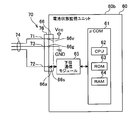
- FIG. 11 shows a functional block diagram of the battery state monitoring unit 60.
- the battery state monitoring unit 60 includes a microcomputer 61 (hereinafter also referred to as “ ⁇ COM 61”) and a lower communication module 65.
- the battery state monitoring unit 60 operates with power supplied from the low-voltage power supply. That is, the low-voltage power supply is connected to the power supply wiring pattern (that is, power supply voltage Vcc) and the ground wiring pattern (that is, ground GND) on the substrate of the battery state monitoring unit 60.
- the ⁇ COM 61 includes a central processing unit (CPU) 62 that performs various processes and controls in accordance with predetermined programs, a ROM 63 that is a read-only memory storing processing programs and various information for the CPU 62, and various data. And a RAM 64 that is a readable / writable memory having an area necessary for processing operations of the CPU 62 and an external interface unit (not shown).
- the ROM 63 stores processing programs that cause the CPU 62 to function as various means.
- the CPU 62 functions as the various means by executing the processing program.
- a lower communication module 65 is connected to the external interface unit.
- the lower communication module 65 is configured to be able to perform communication (LIN communication) using the LIN protocol, which is the serial multiplex communication protocol described above.
- the lower communication module 65 is arranged between the ⁇ COM 61 and the terminal fitting 66s of the connector 66.
- the shared signal line 72 of the wire harness 70 is connected to the lower communication module 65 through the terminal fitting 66s.
- the lower communication module 65 uses the shared signal line 72 to perform LIN communication with the plurality of battery state notification units 39 (that is, the plurality of subunits 40) connected to the shared signal line 72.
- the lower-level communication module 65 outputs various information such as battery status information sent from each battery status notification unit 39 through the shared signal line 72 to the ⁇ COM 61, and also shares various information such as commands sent from the ⁇ COM 61. Output to the battery state notification unit 39 through the signal line 72.
- a higher-level communication module (not shown) is connected to the external interface.
- This higher-level communication module is configured to perform communication using, for example, a well-known CAN (Controller Area Network) protocol, and transmits and receives various types of information to and from an electronic control device mounted on an automobile.
- CAN Controller Area Network
- the battery status monitoring unit 60 (that is, the CPU 62 of the ⁇ COM 61) monitors the status of the plurality of battery packs 10 (1) to (3). First, the battery state monitoring unit 60 transmits the battery state information transmission command through the lower-level communication module 65 to the subunit 40 (A) of the battery state notification unit 39 (1).
- the battery cell 21 that needs to be discharged from the voltage and temperature between the electrodes of the battery cell 21 included in the battery state information. The presence or absence of is determined. If it is determined that there is a battery cell 21 that needs to be discharged, a battery cell discharge command including cell designation information indicating the battery cell 21 to be discharged is sent to the subunit 40 (A) from which the battery state information has been sent. Send to. Subsequently, the same processing as described above is sequentially performed on the other subunits 40 (B) and (C) of the battery state notification unit 39 (1). Then, when the processing for the subunits 40 (A) to (C) of the battery status notification unit 39 (1) is completed, the same processing is performed for the battery status notification units 39 (2) and (3) in order. Thereafter, the above process is repeated at a predetermined interval.
- the wire harness 70 includes a power line 71 as a plurality of electric wires, a shared signal line 72, and a wire part 74 including a ground line 73, a first harness connector 75, and a second harness connector 76.
- the wire harness 70 (3) which connects battery state notification unit 39 (2), (3) is provided.
- the power supply line 71, the shared signal line 72, and the ground line 73 are each configured by a covered electric wire, and one end of each is connected to a plurality of terminal fittings of a first harness connector 75 provided corresponding to each electric wire. Each other end is connected to a plurality of terminal fittings of a second harness connector 76 provided corresponding to each electric wire.
- the first harness connector 75 is configured to be able to fit into a second connector 59 of the subunit 40 described later, and the second harness connector 76 is a connector of the first connector 58 of the subunit 40 and the battery state monitoring unit 60. 66 can be fitted.
- the power line 71 is connected to the male terminal fitting 59v
- the ground line 73 is connected to the male terminal fitting 59g.
- the shared signal line 72 is connected to the male terminal fitting 59s.
- the power line 71 is connected to the female terminal fitting 58v
- the ground line 73 is connected to the female terminal fitting 58g
- the shared signal line 72 is female. It is connected to the terminal fitting 58s.
- the power line 71 is connected to the terminal fitting 66v
- the ground line is connected to the terminal fitting 66g.
- the shared signal line 72 is connected to the terminal fitting 66s.
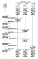
- the subunits 40 (A) to (C) of the battery state notification unit 39 (1) provided in the plurality of battery packs 10 execute the above-described battery cell voltage detection process and battery cell temperature detection process at a predetermined cycle. Then, the interelectrode voltage and temperature of the battery cell 21 are stored in the RAM 53 (W01, W02).
- the battery state monitoring unit 60 transmits a battery state information transmission command (A) to the subunit 40 (A) of the battery state notification unit 39 (1) of one battery pack 10 (1) among the plurality of battery packs 10. (W1). Receiving this battery state information transmission command (A), the subunit 40 (A) executes battery state information transmission processing and transmits the battery state information (A) to the battery state monitoring unit 60 (W11). When the battery state monitoring unit 60 determines from the battery state information (A) that there is no battery cell that needs to be discharged, the battery state monitoring unit 60 proceeds to the next process (W2).
- the battery state monitoring unit 60 transmits a battery state information transmission command (B) to the subunit 40 (B) of the battery state notification unit 39 (1) (W3).
- the subunit 40 (B) executes the battery state information transmission process and transmits the battery state information (B) to the battery state monitoring unit 60 (W21).
- the battery state monitoring unit 60 determines from the battery state information (B) that there is a battery cell that needs to be discharged, the battery state discharge unit includes a battery cell discharge command including cell designation information indicating the battery cell 21 to be discharged. Transmit to the unit (B) and proceed to the next process (W5).
- the battery state notification unit (B) that has received this battery cell discharge command executes the battery cell discharge process (W22).
- the battery state monitoring unit 60 transmits a battery state information transmission command (C) to the subunit 40 (C) of the battery state notification unit 39 (1) (W6).
- the subunit 40 (C) executes battery state information transmission processing and transmits the battery state information (C) to the battery state monitoring unit 60 (W31).
- the battery state monitoring unit 60 determines from the battery state information (C) that there is no battery cell that needs to be discharged, the battery state monitoring unit 60 proceeds to the next process, assuming that the process for the battery pack 10 (1) is finished (W7). ).
- the sub unit 40 includes a first connector 58 constituting information relay means, a second connector 59 provided so as to be fitted to a first connector of another sub unit 40, a first connector 58 and a second connector. 59, the relay wiring pattern 423 for transmitting the battery state information to and from 59, so that the battery state information transmitted by each subunit 40 is connected to each sub unit 40 by connecting the plurality of subunits 40 in series.
- the unit 40 can be aggregated into one subunit 40 arranged at the end via the unit 40, so that only the one subunit 40 is connected to the external battery state monitoring unit 60 or other battery state notification unit 39.
- the battery status monitoring unit 60 can monitor the status of the battery pack 10 based on the battery status information transmitted from the battery status notification unit 39 (that is, the subunit 40) of each battery pack 10, Therefore, the number of the plurality of electric wires in the wire harness 70 can be reduced to the number (three in the present embodiment) necessary for transmitting the battery state information including a digital signal. Therefore, the number of the plurality of electric wires of the wire harness 70 can be reduced, and the wiring design and wiring work of the wire harness 70 can be facilitated. Further, since the battery state information consisting of a digital signal is transmitted to the battery state monitoring unit 60, the voltage level of the signal to be transmitted can be a low voltage of about several volts. Therefore, electrical design such as safety / reliability design such as insulation resistance and noise resistance in the battery state monitoring unit 60 can be facilitated.
- the communication module 55 of each subunit 40 is configured to transmit the battery state information to the battery state monitoring unit 60 using serial communication, the battery state information is compared with the case where parallel communication is used. Therefore, the number of the plurality of electric wires required for transmitting the wire harness 70 is small, so that the number of the plurality of electric wires in the wire harness 70 can be further reduced, and the wiring design and wiring work of the wire harness 70 can be further facilitated.
- the battery pack 10 is provided with a bus bar module 30 having a plurality of bus bars 32 for connecting the positive electrodes 25 and the negative electrodes 26 of the plurality of battery cells 21 to each other, and the battery state notification unit 39 is connected to the bus bar. Since it is provided in the module 30, the battery state notification unit 39 can be provided in the battery pack 10 together with the assembly of the bus bar module 30 to the plurality of battery cells 21, and the assembly work of the battery pack 10 can be facilitated.
- the battery state monitoring unit 60 is attached to one battery pack 10 (1), the battery state monitoring unit 60 and the battery state notification unit 39 (1) of the battery pack 10 (1) are connected.
- the length of the wire harness 70 (1) can be shortened, and the wiring design and wiring work of the wire harness 70 (1) can be further facilitated.
- the plurality of battery state notification units 39 and the battery state monitoring unit 60 are connected by a single bus signal line including the relay wiring pattern 423 and the shared signal line. It is not limited.
- a plurality of lower-level communication modules 65 are provided in one battery state monitoring unit 60, and as shown in FIG. 13, the battery state monitoring unit 60 and a plurality of battery packs 10 (that is, the battery state notification unit 39) May be connected one to one.
- each subunit 40 constituting the battery state notification unit 39 may be connected to the battery state monitoring unit 60 on a one-to-one basis with a wire harness.
- a flying capacitor circuit is provided in the cell voltage input unit 45 of the subunit 40 to separate a high voltage portion (that is, a high voltage system power supply) and a low voltage portion (low voltage system power supply), and Although the high voltage analog signal is converted into the low voltage analog signal, the present invention is not limited to this.
- the cell voltage input unit 45 is configured only by a multiplexer circuit, and the cell voltage input unit 45, the first ADC unit 47, the second ADC unit 48, and the temperature sensor unit.
- the subunit 40 is configured to be operated by the low voltage power supply supplied by the battery state monitoring unit 60, but is not limited thereto.
- the whole subunit 40 may be configured to operate with a high-voltage power supply configured by the battery pack 10 provided with the subunit 40 itself.
- each subunit 40 is replaced with a daisy chain connection (a daisy chain connection) instead of the bus connection hanging on the bus signal line described above.
- the subunit 40 is provided with an upper communication module 56 and a lower communication module 57.
- the upper communication module 56 is connected to the female terminal fitting 58s of the first connector 58 through the relay wiring pattern 423a, so that another subunit 40 on the high potential side further away from the battery state monitoring unit 60 is connected. .
- the ⁇ COM 50 When the ⁇ COM 50 receives information from the other sub-unit 40 on the high potential side through the upper communication module 56, the ⁇ COM 50 relays the information to the other sub-unit 40 on the low potential side from the lower communication module 57, or the battery state monitoring unit. 60. In addition, when the ⁇ COM 50 receives information from another low-voltage side subunit 40 or the battery state monitoring unit 60 through the lower-level communication module 57, the ⁇ COM 50 relays the information as necessary, and passes through the higher-level communication module 56. It transmits to other subunits 40 on the potential side.
Landscapes
- Engineering & Computer Science (AREA)
- Manufacturing & Machinery (AREA)
- Chemical & Material Sciences (AREA)
- Chemical Kinetics & Catalysis (AREA)
- Electrochemistry (AREA)
- General Chemical & Material Sciences (AREA)
- Microelectronics & Electronic Packaging (AREA)
- Secondary Cells (AREA)
- Battery Mounting, Suspending (AREA)
- Connection Of Batteries Or Terminals (AREA)
Abstract
Cette invention concerne une unité de notification de statut de batterie permutant facilement entre des blocs-piles comprenant chacun un nombre différent de piles, un module de barre omnibus et une batterie assemblée comprenant une telle unité de notification de statut de batterie, ainsi qu'un système de surveillance de statut de batterie comprenant une telle unité de notification de statut de batterie. Ladite unité de notification de statut de batterie (39) comprend une pluralité de sous-unités (40) correspondant à chacune des piles (21) d'un nombre prédéterminé de piles. Sur la base d'un signal de tension de pile correspondant à une tension inter-électrodes fournie par une barre omnibus (32) et une borne de raccordement (33), et d'un signal de température de pile correspondant à une tension fournie par une unité de capteur de température (34), lesdites sous-unités (40) génèrent des informations de statut de batterie consistant en un signal numérique qui contient des informations indiquant le statut des piles (21) correspondant aux sous-unités (40), et transmettent les informations de statut de batterie à un système externe de surveillance de statut de batterie (60).
Priority Applications (3)
| Application Number | Priority Date | Filing Date | Title |
|---|---|---|---|
| EP12818313.4A EP2738863A4 (fr) | 2011-07-27 | 2012-07-23 | Unité de notification de statut de batterie, module de barre omnibus, batterie assemblée et système de surveillance de statut de batterie |
| CN201280047384.1A CN103959552B (zh) | 2011-07-27 | 2012-07-23 | 汇流条模块、电池组和电池状态监测系统 |
| US14/165,267 US9466862B2 (en) | 2011-07-27 | 2014-01-27 | Battery state notifying unit, bus bar module, battery pack, and battery state monitoring system |
Applications Claiming Priority (2)
| Application Number | Priority Date | Filing Date | Title |
|---|---|---|---|
| JP2011164227A JP5825904B2 (ja) | 2011-07-27 | 2011-07-27 | 電池状態通知ユニット、バスバモジュール、組電池、及び、電池状態監視システム |
| JP2011-164227 | 2011-07-27 |
Related Child Applications (1)
| Application Number | Title | Priority Date | Filing Date |
|---|---|---|---|
| US14/165,267 Continuation US9466862B2 (en) | 2011-07-27 | 2014-01-27 | Battery state notifying unit, bus bar module, battery pack, and battery state monitoring system |
Publications (1)
| Publication Number | Publication Date |
|---|---|
| WO2013015235A1 true WO2013015235A1 (fr) | 2013-01-31 |
Family
ID=47601082
Family Applications (1)
| Application Number | Title | Priority Date | Filing Date |
|---|---|---|---|
| PCT/JP2012/068559 Ceased WO2013015235A1 (fr) | 2011-07-27 | 2012-07-23 | Unité de notification de statut de batterie, module de barre omnibus, batterie assemblée et système de surveillance de statut de batterie |
Country Status (5)
| Country | Link |
|---|---|
| US (1) | US9466862B2 (fr) |
| EP (1) | EP2738863A4 (fr) |
| JP (1) | JP5825904B2 (fr) |
| CN (1) | CN103959552B (fr) |
| WO (1) | WO2013015235A1 (fr) |
Cited By (7)
| Publication number | Priority date | Publication date | Assignee | Title |
|---|---|---|---|---|
| WO2014014000A1 (fr) * | 2012-07-20 | 2014-01-23 | 矢崎総業株式会社 | Module de barre omnibus |
| US20150111073A1 (en) * | 2013-10-22 | 2015-04-23 | Denso Corportion | Battery pack unit integrating bus bar unit, cell monitor substrate and control unit |
| CN104979517A (zh) * | 2014-04-11 | 2015-10-14 | 三星Sdi株式会社 | 电池模块 |
| CN105144463A (zh) * | 2013-04-23 | 2015-12-09 | 爱尔铃克铃尔股份公司 | 用于电化学装置的电池接触系统 |
| WO2016031635A1 (fr) * | 2014-08-27 | 2016-03-03 | 株式会社 豊田自動織機 | Support de piles |
| JP2018054334A (ja) * | 2016-09-26 | 2018-04-05 | 矢崎総業株式会社 | 電池状態検出装置 |
| CN111656566A (zh) * | 2017-09-12 | 2020-09-11 | 重庆金康新能源汽车有限公司 | 电动汽车电池管理系统的集成感测板 |
Families Citing this family (31)
| Publication number | Priority date | Publication date | Assignee | Title |
|---|---|---|---|---|
| JP5975296B2 (ja) * | 2013-03-27 | 2016-08-23 | 株式会社オートネットワーク技術研究所 | 配線モジュール |
| JP6098939B2 (ja) | 2013-04-08 | 2017-03-22 | 株式会社Gsユアサ | 蓄電モジュール |
| US10003108B2 (en) | 2013-11-14 | 2018-06-19 | Nec Corporation | Storage battery, method of controlling storage battery, and non-transitory storage medium |
| EP3149499B1 (fr) * | 2014-06-02 | 2018-01-31 | Volvo Truck Corporation | Procédé et système permettant de surveiller l'état d'éléments de batterie |
| DE102014215035A1 (de) * | 2014-07-31 | 2016-02-04 | Bayerische Motoren Werke Aktiengesellschaft | Batteriesystem und elektrisch angetriebenes Zweirad mit einem Batteriesystem |
| US10627453B2 (en) * | 2014-10-28 | 2020-04-21 | Sanyo Electric Co., Ltd. | Integrated circuit with built-in status monitoring unit and power supply device provided with said integrated circuit |
| JP6233654B2 (ja) * | 2014-11-25 | 2017-11-22 | 株式会社オートネットワーク技術研究所 | 配線モジュール |
| JP6265157B2 (ja) * | 2015-03-26 | 2018-01-24 | トヨタ自動車株式会社 | 通信システム |
| JP2017049199A (ja) * | 2015-09-04 | 2017-03-09 | トヨタ自動車株式会社 | 電圧監視装置 |
| US10371758B2 (en) * | 2015-09-15 | 2019-08-06 | Lg Chem, Ltd. | Test system and method for testing a battery pack |
| JP6531705B2 (ja) * | 2016-04-21 | 2019-06-19 | 株式会社デンソー | 回転電機の制御装置 |
| JP2018026285A (ja) | 2016-08-10 | 2018-02-15 | 矢崎総業株式会社 | 電池監視ユニット |
| JP6899637B2 (ja) * | 2016-09-07 | 2021-07-07 | 株式会社クボタ | バッテリパック |
| EP3316389B1 (fr) * | 2016-10-26 | 2024-01-03 | Samsung SDI Co., Ltd. | Système de batterie, circuit de communication pour un système de batterie et véhicule |
| JP6490656B2 (ja) * | 2016-11-18 | 2019-03-27 | 矢崎総業株式会社 | 導電モジュール及び電池パック |
| JP6720847B2 (ja) * | 2016-12-14 | 2020-07-08 | 株式会社デンソー | 電池パック |
| CN206758541U (zh) * | 2017-03-31 | 2017-12-15 | 创科(澳门离岸商业服务)有限公司 | 主电池、副电池以及电池组 |
| JP2018181780A (ja) * | 2017-04-21 | 2018-11-15 | 矢崎総業株式会社 | 積層バスバおよび電池モジュール |
| DE102017207943A1 (de) * | 2017-05-11 | 2018-11-15 | Robert Bosch Gmbh | Signalbearbeitungsvorrichtung für ein insbesondere in ein Batteriesystem einsetzbares Kommunikationssystem |
| CN107579179A (zh) * | 2017-08-28 | 2018-01-12 | 长兴遥米新能源科技有限公司 | 一种快速冷却锂电池模组 |
| CN108683262A (zh) * | 2018-06-21 | 2018-10-19 | 桑顿新能源科技有限公司 | 一种储能模组及模块化储能机柜 |
| KR102698610B1 (ko) * | 2018-11-15 | 2024-08-27 | 주식회사 엘지에너지솔루션 | 배터리 모듈 |
| KR102848070B1 (ko) * | 2020-01-07 | 2025-08-19 | 주식회사 엘지에너지솔루션 | Hv 와이어 어셈블리를 포함하는 배터리 팩 및 상기 배터리 팩의 제조 방법 |
| JP2021125425A (ja) * | 2020-02-07 | 2021-08-30 | Apb株式会社 | リチウムイオン電池システムおよび電池状態推定システム |
| US11299063B2 (en) * | 2020-02-12 | 2022-04-12 | GM Global Technology Operations LLC | Method and apparatus for controlling electric power flow in a battery system |
| CN111653719B (zh) * | 2020-05-26 | 2023-05-30 | 武汉中原长江科技发展有限公司 | 一种高能量密度电池组、多电芯切换测试装置和测试方法 |
| CN113964397B (zh) * | 2021-09-17 | 2025-01-24 | 深圳市沛城电子科技股份有限公司 | 电芯采样装置、方法、电池管理系统及电池包 |
| JPWO2023162751A1 (fr) * | 2022-02-25 | 2023-08-31 | ||
| AU2023288165A1 (en) * | 2022-06-22 | 2025-01-23 | Sunvertec Pty Ltd | A battery energy storage system |
| CN115327379B (zh) * | 2022-08-31 | 2025-06-17 | 杭电(海宁)信息科技研究院有限公司 | 一种锂电池测温装置 |
| JP2025066055A (ja) * | 2023-10-10 | 2025-04-22 | 恵州億緯▲リ▼能股▲フン▼有限公司 | 電気モジュールと電池パック |
Citations (5)
| Publication number | Priority date | Publication date | Assignee | Title |
|---|---|---|---|---|
| JPH11248755A (ja) | 1998-03-06 | 1999-09-17 | Matsushita Electric Ind Co Ltd | 積層電圧計測装置 |
| JP2006337130A (ja) | 2005-06-01 | 2006-12-14 | Yazaki Corp | フライングキャパシタ方式電圧測定装置 |
| JP2007059088A (ja) * | 2005-08-22 | 2007-03-08 | Nissan Motor Co Ltd | 組電池 |
| JP2010003627A (ja) * | 2008-06-23 | 2010-01-07 | Autonetworks Technologies Ltd | ハーネス及び電池装置 |
| JP2011076936A (ja) | 2009-09-30 | 2011-04-14 | Toshiba Corp | 組電池およびこれを備えた二次電池装置 |
Family Cites Families (7)
| Publication number | Priority date | Publication date | Assignee | Title |
|---|---|---|---|---|
| US5496658A (en) * | 1994-07-25 | 1996-03-05 | Exide Corporation | Storage battery state-of-charge indicator |
| EP1332924A1 (fr) * | 2000-10-13 | 2003-08-06 | Lear Automotive (EEDS) Spain, S.L. | Dispositif de protection destine a la batterie d'allumage d'un vehicule et au reseau electrique qu'elle alimente |
| US6628102B2 (en) * | 2001-04-06 | 2003-09-30 | Microchip Technology Inc. | Current measuring terminal assembly for a battery |
| US7205746B2 (en) * | 2001-04-06 | 2007-04-17 | Microchip Technology Inc. | Battery cover assembly having integrated battery condition monitoring |
| US7859223B2 (en) * | 2007-01-31 | 2010-12-28 | Analog Devices, Inc. | Battery montoring apparatus and daisy chain interface suitable for use in a battery monitoring apparatus |
| US9270133B2 (en) * | 2007-04-02 | 2016-02-23 | Linear Technology Corporation | Monitoring cells in energy storage system |
| JP4823345B2 (ja) * | 2009-09-18 | 2011-11-24 | 三菱重工業株式会社 | 電池システム |
-
2011
- 2011-07-27 JP JP2011164227A patent/JP5825904B2/ja active Active
-
2012
- 2012-07-23 CN CN201280047384.1A patent/CN103959552B/zh active Active
- 2012-07-23 WO PCT/JP2012/068559 patent/WO2013015235A1/fr not_active Ceased
- 2012-07-23 EP EP12818313.4A patent/EP2738863A4/fr not_active Withdrawn
-
2014
- 2014-01-27 US US14/165,267 patent/US9466862B2/en active Active
Patent Citations (5)
| Publication number | Priority date | Publication date | Assignee | Title |
|---|---|---|---|---|
| JPH11248755A (ja) | 1998-03-06 | 1999-09-17 | Matsushita Electric Ind Co Ltd | 積層電圧計測装置 |
| JP2006337130A (ja) | 2005-06-01 | 2006-12-14 | Yazaki Corp | フライングキャパシタ方式電圧測定装置 |
| JP2007059088A (ja) * | 2005-08-22 | 2007-03-08 | Nissan Motor Co Ltd | 組電池 |
| JP2010003627A (ja) * | 2008-06-23 | 2010-01-07 | Autonetworks Technologies Ltd | ハーネス及び電池装置 |
| JP2011076936A (ja) | 2009-09-30 | 2011-04-14 | Toshiba Corp | 組電池およびこれを備えた二次電池装置 |
Non-Patent Citations (1)
| Title |
|---|
| See also references of EP2738863A4 |
Cited By (12)
| Publication number | Priority date | Publication date | Assignee | Title |
|---|---|---|---|---|
| WO2014014000A1 (fr) * | 2012-07-20 | 2014-01-23 | 矢崎総業株式会社 | Module de barre omnibus |
| CN105144463A (zh) * | 2013-04-23 | 2015-12-09 | 爱尔铃克铃尔股份公司 | 用于电化学装置的电池接触系统 |
| CN105144463B (zh) * | 2013-04-23 | 2020-04-14 | 爱尔铃克铃尔股份公司 | 用于电化学装置的电池接触系统 |
| US20150111073A1 (en) * | 2013-10-22 | 2015-04-23 | Denso Corportion | Battery pack unit integrating bus bar unit, cell monitor substrate and control unit |
| CN104979517A (zh) * | 2014-04-11 | 2015-10-14 | 三星Sdi株式会社 | 电池模块 |
| CN104979517B (zh) * | 2014-04-11 | 2019-08-23 | 三星Sdi株式会社 | 电池模块 |
| WO2016031635A1 (fr) * | 2014-08-27 | 2016-03-03 | 株式会社 豊田自動織機 | Support de piles |
| JP2016048623A (ja) * | 2014-08-27 | 2016-04-07 | 株式会社豊田自動織機 | 電池モジュール |
| US9972870B2 (en) | 2014-08-27 | 2018-05-15 | Kabushiki Kaisha Toyota Jidoshokki | Battery module |
| JP2018054334A (ja) * | 2016-09-26 | 2018-04-05 | 矢崎総業株式会社 | 電池状態検出装置 |
| CN111656566A (zh) * | 2017-09-12 | 2020-09-11 | 重庆金康新能源汽车有限公司 | 电动汽车电池管理系统的集成感测板 |
| CN111656566B (zh) * | 2017-09-12 | 2023-04-28 | 重庆金康新能源汽车有限公司 | 电动汽车电池管理系统的集成感测板 |
Also Published As
| Publication number | Publication date |
|---|---|
| JP2013030312A (ja) | 2013-02-07 |
| EP2738863A1 (fr) | 2014-06-04 |
| US9466862B2 (en) | 2016-10-11 |
| JP5825904B2 (ja) | 2015-12-02 |
| CN103959552B (zh) | 2017-02-15 |
| CN103959552A (zh) | 2014-07-30 |
| US20140141301A1 (en) | 2014-05-22 |
| EP2738863A4 (fr) | 2015-04-22 |
Similar Documents
| Publication | Publication Date | Title |
|---|---|---|
| JP5825904B2 (ja) | 電池状態通知ユニット、バスバモジュール、組電池、及び、電池状態監視システム | |
| JP5739244B2 (ja) | 電池状態通知ユニット、バスバモジュール、組電池、及び、電池状態監視システム | |
| JP3930171B2 (ja) | 組電池の監視装置 | |
| US8427110B2 (en) | Battery system | |
| JP5747900B2 (ja) | 電池監視装置 | |
| EP4336643B1 (fr) | Carte de connexion modulaire et procédé de connexion d'une carte de connexion modulaire | |
| JP2010537362A (ja) | 二次電池パックまたは一次電池パック | |
| CN110832334B (zh) | 故障诊断装置 | |
| US10587017B2 (en) | Battery modules having a plurality of submodules | |
| JP2022103705A (ja) | バッテリセンシングユニット及びバッテリ用バスバーモジュール | |
| US20170066343A1 (en) | Voltage monitoring system | |
| CN114388972A (zh) | 电池组 | |
| US10326442B2 (en) | Assembly having internally configurable solid-state switch arrangement for use as one or more disconnection switches in electrical systems and having external package common to the electrical systems | |
| WO2011078404A2 (fr) | Circuit hybride | |
| KR102331063B1 (ko) | 배터리 모듈 | |
| JP2017005889A (ja) | 電池パック | |
| JP5910538B2 (ja) | 電池監視装置 | |
| US11280838B2 (en) | Integrated circuit and battery monitoring device | |
| US20250070401A1 (en) | Battery system and method of assembling a battery system | |
| US20240194957A1 (en) | Battery module assembly structure for vehicles | |
| JP2024106542A (ja) | 電気コネクタおよび電池制御基板モジュール | |
| JP2024106544A (ja) | 電池接続モジュール、電池モジュールおよび電池パック | |
| CN117728529A (zh) | 用于监测和控制电池的系统,电池管理系统 | |
| JP2016213984A (ja) | 電池モジュールおよび電源装置 |
Legal Events
| Date | Code | Title | Description |
|---|---|---|---|
| 121 | Ep: the epo has been informed by wipo that ep was designated in this application |
Ref document number: 12818313 Country of ref document: EP Kind code of ref document: A1 |
|
| NENP | Non-entry into the national phase |
Ref country code: DE |
|
| WWE | Wipo information: entry into national phase |
Ref document number: 2012818313 Country of ref document: EP |