WO2013015256A1 - 電力管理システム及び管理方法 - Google Patents
電力管理システム及び管理方法 Download PDFInfo
- Publication number
- WO2013015256A1 WO2013015256A1 PCT/JP2012/068621 JP2012068621W WO2013015256A1 WO 2013015256 A1 WO2013015256 A1 WO 2013015256A1 JP 2012068621 W JP2012068621 W JP 2012068621W WO 2013015256 A1 WO2013015256 A1 WO 2013015256A1
- Authority
- WO
- WIPO (PCT)
- Prior art keywords
- power
- storage battery
- pcs
- storage
- predetermined
- Prior art date
- Legal status (The legal status is an assumption and is not a legal conclusion. Google has not performed a legal analysis and makes no representation as to the accuracy of the status listed.)
- Ceased
Links
Images


Classifications
-
- H—ELECTRICITY
- H02—GENERATION; CONVERSION OR DISTRIBUTION OF ELECTRIC POWER
- H02J—ELECTRIC POWER NETWORKS; CIRCUIT ARRANGEMENTS OR SYSTEMS FOR SUPPLYING OR DISTRIBUTING ELECTRIC POWER; SYSTEMS FOR STORING ELECTRIC ENERGY
- H02J3/00—Circuit arrangements for AC mains or AC distribution networks
- H02J3/28—Arrangements for balancing of the load in networks by storage of energy
- H02J3/32—Arrangements for balancing of the load in networks by storage of energy using batteries or super capacitors with converting means
-
- H—ELECTRICITY
- H02—GENERATION; CONVERSION OR DISTRIBUTION OF ELECTRIC POWER
- H02J—ELECTRIC POWER NETWORKS; CIRCUIT ARRANGEMENTS OR SYSTEMS FOR SUPPLYING OR DISTRIBUTING ELECTRIC POWER; SYSTEMS FOR STORING ELECTRIC ENERGY
- H02J3/00—Circuit arrangements for AC mains or AC distribution networks
-
- H—ELECTRICITY
- H02—GENERATION; CONVERSION OR DISTRIBUTION OF ELECTRIC POWER
- H02J—ELECTRIC POWER NETWORKS; CIRCUIT ARRANGEMENTS OR SYSTEMS FOR SUPPLYING OR DISTRIBUTING ELECTRIC POWER; SYSTEMS FOR STORING ELECTRIC ENERGY
- H02J3/00—Circuit arrangements for AC mains or AC distribution networks
- H02J3/38—Arrangements for feeding a single network from two or more generators or sources in parallel; Arrangements for feeding already energised networks from additional generators or sources in parallel
- H02J3/381—Dispersed generators
-
- H—ELECTRICITY
- H02—GENERATION; CONVERSION OR DISTRIBUTION OF ELECTRIC POWER
- H02J—ELECTRIC POWER NETWORKS; CIRCUIT ARRANGEMENTS OR SYSTEMS FOR SUPPLYING OR DISTRIBUTING ELECTRIC POWER; SYSTEMS FOR STORING ELECTRIC ENERGY
- H02J7/00—Circuit arrangements for charging or discharging batteries or for supplying loads from batteries
-
- H—ELECTRICITY
- H02—GENERATION; CONVERSION OR DISTRIBUTION OF ELECTRIC POWER
- H02J—ELECTRIC POWER NETWORKS; CIRCUIT ARRANGEMENTS OR SYSTEMS FOR SUPPLYING OR DISTRIBUTING ELECTRIC POWER; SYSTEMS FOR STORING ELECTRIC ENERGY
- H02J2101/00—Supply or distribution of decentralised, dispersed or local electric power generation
- H02J2101/20—Dispersed power generation using renewable energy sources
- H02J2101/22—Solar energy
- H02J2101/24—Photovoltaics
-
- Y—GENERAL TAGGING OF NEW TECHNOLOGICAL DEVELOPMENTS; GENERAL TAGGING OF CROSS-SECTIONAL TECHNOLOGIES SPANNING OVER SEVERAL SECTIONS OF THE IPC; TECHNICAL SUBJECTS COVERED BY FORMER USPC CROSS-REFERENCE ART COLLECTIONS [XRACs] AND DIGESTS
- Y02—TECHNOLOGIES OR APPLICATIONS FOR MITIGATION OR ADAPTATION AGAINST CLIMATE CHANGE
- Y02E—REDUCTION OF GREENHOUSE GAS [GHG] EMISSIONS, RELATED TO ENERGY GENERATION, TRANSMISSION OR DISTRIBUTION
- Y02E10/00—Energy generation through renewable energy sources
- Y02E10/50—Photovoltaic [PV] energy
- Y02E10/56—Power conversion systems, e.g. maximum power point trackers
-
- Y—GENERAL TAGGING OF NEW TECHNOLOGICAL DEVELOPMENTS; GENERAL TAGGING OF CROSS-SECTIONAL TECHNOLOGIES SPANNING OVER SEVERAL SECTIONS OF THE IPC; TECHNICAL SUBJECTS COVERED BY FORMER USPC CROSS-REFERENCE ART COLLECTIONS [XRACs] AND DIGESTS
- Y02—TECHNOLOGIES OR APPLICATIONS FOR MITIGATION OR ADAPTATION AGAINST CLIMATE CHANGE
- Y02E—REDUCTION OF GREENHOUSE GAS [GHG] EMISSIONS, RELATED TO ENERGY GENERATION, TRANSMISSION OR DISTRIBUTION
- Y02E70/00—Other energy conversion or management systems reducing GHG emissions
- Y02E70/30—Systems combining energy storage with energy generation of non-fossil origin
Definitions
- the present invention relates to a power management system and a management method including a power generation device and a storage battery.
- EMS Energy Management System
- Such EMS performs control (reverse power flow control) or the like that outputs supply power supplied by the power generator to the power system (for example, Patent Document 1).
- the voltage value of the power system increases.
- the voltage value of the power system reaches the allowable voltage value so that the voltage value of the power system exceeds the allowable voltage value allowed for the power system and power is not output to the power system, the power output by the power generator to the power system (Reverse power flow) is suppressed.
- the power (reverse power flow) output from the power generator to the power system is suppressed.
- the power generation device is a device that generates electric power using natural energy
- the utilization efficiency of natural energy decreases.
- the follow-up of the power generation amount is not excellent, the power generated by the power generation device is wasted.
- the power management system includes a power generation device that generates electric power and a storage battery that stores electric power, and is connected to an electric power system.
- the power management system includes a control unit that controls an operation mode of the storage battery so that charging of the storage battery is started when a voltage value of the power system exceeds a predetermined system voltage threshold.
- the control unit When the voltage value of the power system exceeds the predetermined system voltage threshold value, the control unit directly supplies power supplied from the power generation device to the storage battery without passing through the power system. Thus, the connection between the power generation device and the storage battery is controlled.
- the power management system includes a first control unit that controls the storage battery.
- the first control unit detects whether a voltage value of the power system exceeds the predetermined system voltage threshold value, and configures the control unit.
- the power management system includes a second control unit that controls the power generation device.
- the second control unit detects whether the voltage value of the power system exceeds the predetermined system voltage threshold value, and configures the control unit.
- control unit controls an operation mode of the storage battery so that charging of the storage battery is stopped when a voltage value of the power system falls below a predetermined system voltage threshold.
- control unit controls an operation mode of the storage battery so that charging of the storage battery is stopped when a storage amount of the storage battery exceeds a predetermined storage amount.
- control unit controls an operation mode of the storage battery so that charging of the storage battery is stopped when a power generation amount of the power generation device falls below a predetermined power generation amount.
- the power management method includes a power generation device that generates power and a storage battery that stores power, and is a method used in a power management system connected to the power system.
- the power management method includes a step of controlling an operation mode of the storage battery so that charging of the storage battery is started when a voltage value of the power system exceeds a predetermined system voltage threshold.
- FIG. 1 is a diagram illustrating an outline of a power management system according to the first embodiment.
- FIG. 2 is a diagram illustrating details of the power management system according to the first embodiment.
- FIG. 3 is a diagram illustrating the operation of the power management system according to the first embodiment.
- FIG. 4 is a diagram illustrating the operation of the power management system according to the first embodiment.
- FIG. 5 is a diagram illustrating the operation of the power management system according to the first embodiment.
- FIG. 6 is a diagram illustrating the operation of the power management system according to the first embodiment.
- FIG. 7 is a diagram illustrating the operation of the power management system according to the first embodiment.
- FIG. 8 is a diagram illustrating the operation of the power management system according to the first embodiment.
- the power management system includes a power generation device that generates power and a storage battery that stores the power, and is connected to the power system.
- the power management system includes a control unit that controls an operation mode of the storage battery so that charging of the storage battery is started when the voltage value of the power system exceeds a predetermined system voltage threshold.
- the predetermined system voltage threshold value may be an allowable voltage value or a value obtained by subtracting a predetermined margin from the allowable voltage value.
- the control unit controls the operation mode of the storage battery so that charging of the storage battery is started when the voltage value of the power system exceeds a predetermined system voltage threshold. Therefore, in the case where the electric power generated by the power generation device is supplied to the storage battery via the power system, the load connected to the power system increases, and the increase in the voltage value of the power system is suppressed. In the case where the power generated by the power generation device is supplied to the storage battery without going through the power system, the power generated by the power generation device is used without affecting the voltage value of the power system. Thereby, it is possible to make use of the power generation capability of the power generation device.
- the power generation device is a solar cell, a wind power generation device, a hydroelectric power generation device, or the like that uses natural energy.
- the power generation device is a fuel cell that uses fuel such as gas.
- the storage battery may be a battery provided in EV (Electric Vehicle).
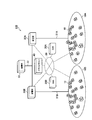
- FIG. 1 is a diagram illustrating an outline of a power management system 100 according to the first embodiment.
- the power management system 100 includes a customer 10, an EMS 20, a substation 30, a smart server 40, and a power plant 50.
- the customer 10, the EMS 20, the substation 30 and the smart server 40 are connected by a network 60.
- Customer 10 has a distributed power source such as a solar battery. Further, the customer 10 may have other power supply means such as a storage battery as a distributed power source.
- the consumer 10 may be a single-family house, an apartment house such as a condominium, a commercial facility such as a building, or a factory.
- a plurality of consumers 10 constitutes a customer group 10A and a customer group 10B.
- the consumer group 10A and the consumer group 10B are classified by, for example, a geographical area.
- the EMS20 controls the interconnection between the some customer 10 and an electric power grid
- the EMS 20 may be referred to as a CEMS (Cluster Energy Management System) in order to manage a plurality of consumers 10. Specifically, the EMS 20 disconnects between the plurality of consumers 10 and the power system at the time of a power failure or the like. On the other hand, the EMS 20 interconnects the plurality of consumers 10 and the power system when power is restored.
- CEMS Cluster Energy Management System
- the EMS 20A and EMS 20B are provided in the first embodiment.
- the EMS 20A controls, for example, interconnection between the customer 10 included in the customer group 10A and the power system.
- the EMS 20B controls interconnection between the customer 10 included in the customer group 10B and the power system.
- the substation 30 supplies power to the plurality of consumers 10 via the distribution line 31. Specifically, the substation 30 steps down the voltage supplied from the power plant 50.
- a substation 30A and a substation 30B are provided.
- the substation 30A supplies power to the consumers 10 included in the consumer group 10A via the distribution line 31A.
- the substation 30B supplies power to the consumers 10 included in the customer group 10B via the distribution line 31B.
- the smart server 40 manages a plurality of EMSs 20 (here, EMS 20A and EMS 20B).
- the smart server 40 also manages a plurality of substations 30 (here, the substation 30A and the substation 30B).
- the smart server 40 comprehensively manages the customers 10 included in the customer group 10A and the customer group 10B.
- the smart server 40 has a function of balancing the power to be supplied to the consumer group 10A and the power to be supplied to the consumer group 10B.
- the power plant 50 generates power using thermal power, wind power, hydraulic power, nuclear power, and the like.
- the power plant 50 supplies power to the plurality of substations 30 (here, the substation 30A and the substation 30B) via the power transmission line 51.
- FIG. 2 is a diagram illustrating details of the power management system 100 according to the first embodiment.
- the above-described consumer 10 will be described as an example.
- the power management system 100 includes a solar cell 211 (hereinafter referred to as PV211), a fuel cell 212 (hereinafter referred to as SOFC212), a storage battery 213, an electric vehicle 214 (hereinafter referred to as EV214), and a PV-PCS220. And an SOFC-PCS 230, a power storage PCS 240, a charger 250, a transmission / reception unit 260, and a display unit 270.
- PV211 solar cell 211
- SOFC212 fuel cell 212
- EV214 electric vehicle 214
- PV-PCS220 an electric vehicle 214
- PV211 is an example of a power generator that generates electric power. Specifically, the PV 211 generates electric power using natural energy (sunlight).
- the SOFC 212 is an example of a power generation device that generates electric power. Specifically, the SOFC 212 generates electric power using a fuel such as hydrogen or natural gas. It should be noted that a certain period of time is required after the instruction to change the power generation amount of the SOFC 212 is made until the power generation amount of the SOFC 212 is actually changed. In other words, the follow-up of the power generation amount of the SOFC 212 is not excellent.
- the storage battery 213 is a device that stores electric power.
- the EV 214 includes a battery that stores electric power. That is, the storage battery 213 and the EV 214 are examples of storage batteries that store electric power.
- the PV-PCS 220 is a device (Power Conditioning System) that controls the PV 211.
- the PV-PCS 220 includes a DC / DC 221 and an inverter DC / AC 222.
- DC / DC 221 is connected to PV 211 and inverter DC / AC 222.
- the DC / DC 221 boosts the voltage of power output from the PV 211.
- the inverter DC / AC 222 is connected to the DC / DC 221 and is connected to the power system (distribution line 31) or the power storage PCS 240 via a switch (not shown).
- the inverter DC / AC 222 converts the DC power supplied from the DC / DC 221 into AC power.
- inverter DC / AC 222 is connected to the power system.
- inverter DC / AC 222 is connected to power storage PCS 240.
- the SOFC-PCS 230 is a device (Power Conditioning System) that controls the SOFC 212.
- the SOFC-PCS 230 includes a DC / DC 231, a DC / DC 232, an inverter DC / AC 233, and an AC / DC 234.
- DC / DC 231 is connected to SOFC 212 and inverter DC / AC 233.
- the DC / DC 231 boosts the voltage of power output from the SOFC 212.
- the DC / DC 232 is connected to the SOFC 212, and the power generated by the SOFC 212 is stepped down and supplied to the control power source.
- the AC / DC 234 is connected to the DC / DC 232 and the power storage PCS 240, converts AC power supplied from the power storage PCS 240 into DC power, and is supplied to the control power source.
- the power generated by the DC / DC 232 is used as startup power for the SOFC 212.
- the inverter DC / AC 233 is connected to the DC / DC 231 and the power system (distribution line 31).
- the inverter DC / AC 233 converts the DC power supplied from the DC / DC 231 into AC power.
- the power storage PCS 240 is a device (Power Conditioning System) that controls the storage battery 213.
- the power storage PCS 240 includes an insulating DC / DC 241, a bidirectional inverter 242, a bidirectional DC / DC 243, and a relay 244 (hereinafter referred to as RY244).
- the insulated DC / DC 241 is connected to the SOFC 212 and the bidirectional DC / DC 243.
- the isolated DC / DC 241 boosts the voltage of the power supplied from the SOFC 212.
- the bidirectional inverter 242 is connected to the isolated DC / DC 241, PV-PCS 220, power system (distribution line 31), and specific load.
- the bidirectional inverter 242 converts the DC power supplied from the isolated DC / DC 241 into AC power.
- the bidirectional inverter 242 converts AC power supplied from the PV-PCS 220 or the power system into DC power.
- the specific load is a load that is connected to the power system via an internal relay in a normal time, and that operates by AC power supplied by the bidirectional inverter 242 during a power failure.
- the bidirectional DC / DC 243 is connected to the insulated DC / DC 241 and the bidirectional inverter 242, and is connected to the storage battery 213 via the RY244.
- the bidirectional DC / DC 243 steps down the voltage of the power supplied from the isolated DC / DC 241 or the bidirectional inverter 242.
- the bidirectional DC / DC 243 boosts the voltage of power supplied from the storage battery 213.
- RY244 is connected to the storage battery 213 and is connected to the EV 214 via the charger 250.
- the RY 244 switches between supplying electric power supplied from the bidirectional DC / DC 243 to the storage battery 213 or supplying electric power supplied from the bidirectional DC / DC 243 to the EV 214 via the charger 250.
- Charger 250 controls charging of a battery provided in EV 214.
- the charger 250 includes a connector for connecting to the EV 214.
- the transmission / reception unit 260 is connected to the power storage PCS 240 and operates with the power stored in the storage battery 213 (or EV 214).
- the transmission / reception unit 260 is connected to a communication line, and receives information from the PV-PCS 220, the SOFC-PCS 230, the power storage PCS 240, and the charger 250.
- the transmission / reception unit 260 is connected to a communication line and transmits information to the PV-PCS 220, the SOFC-PCS 230, the power storage PCS 240, and the charger 250.
- the transmission / reception part 260 is connected to the display part 270 by radio
- Display unit 270 is connected to power storage PCS 240 and operates with the power stored in storage battery 213 (or EV 214). Display unit 270 displays information received from transmission / reception unit 260.
- the PV-PCS 220 or the power storage PCS 240 constitutes a control unit that controls the operation mode of the storage battery 213 (or EV 214).
- the PV-PCS 220 constitutes a control unit
- the PV-PCS 220 has a function of monitoring the voltage value of the power system, and the voltage value of the power system exceeds the predetermined system voltage threshold. It is detected whether or not.
- PV-PCS 220 controls the operation mode of storage battery 213 (or EV 214) so that charging of storage battery 213 (or EV 214) is started when the voltage value of the power system exceeds a predetermined system voltage threshold. Specifically, PV-PCS 220 transmits a charge mode transition instruction to power storage PCS 240 via the communication line.
- the predetermined system voltage threshold value may be an allowable voltage value or a value obtained by subtracting a predetermined margin from the allowable voltage value.
- the PV-PCS 220 controls the operation mode of the storage battery 213 (or EV 214) so that charging of the storage battery 213 (or EV 214) is stopped when the voltage value of the power system falls below a predetermined system voltage threshold. Specifically, PV-PCS 220 transmits a charge mode release instruction to power storage PCS 240 via the communication line.
- the predetermined system voltage threshold for starting charging and the predetermined system voltage threshold for stopping charging may be different from each other.
- the predetermined system voltage threshold value for starting charging may be higher than the predetermined system voltage threshold value for stopping charging.
- the PV-PCS 220 controls the operation mode of the storage battery 213 (or EV 214) when the storage amount of the storage battery 213 (or EV 214) exceeds a predetermined storage amount. Specifically, PV-PCS 220 transmits a charge mode release instruction to power storage PCS 240 via the communication line.
- the predetermined storage amount is determined according to the storage amount (full charge storage amount) when the storage battery 213 (or EV 214) is fully charged.
- the predetermined charged amount may be a fully charged charged amount or a value obtained by subtracting a predetermined margin from the fully charged charged amount.
- the PV-PCS 220 controls the operation mode of the storage battery 213 (or EV 214) when the power generation amount of the PV 211 falls below a predetermined power generation amount. Specifically, PV-PCS 220 transmits a charge mode release instruction to power storage PCS 240 via the communication line.
- the predetermined power generation amount can be arbitrarily determined.
- the predetermined power generation amount is a power generation amount at a level at which power necessary for charging cannot be supplied.
- the power storage PCS 240 when the power storage PCS 240 forms a control unit, the power storage PCS 240 has a function of monitoring the voltage value of the power system, and whether or not the voltage value of the power system exceeds the predetermined system voltage threshold value. To detect.
- the power storage PCS 240 controls the operation mode of the storage battery 213 (or EV 214) so that charging of the storage battery 213 (or EV 214) is started when the voltage value of the power system exceeds a predetermined system voltage threshold.
- the power storage PCS 240 controls the operation mode of the storage battery 213 (or EV 214) so as to stop charging the storage battery 213 (or EV 214) when the voltage value of the power system falls below a predetermined system voltage threshold.
- the storage PCS 240 controls the operation mode of the storage battery 213 (or EV 214) when the storage amount of the storage battery 213 (or EV 214) exceeds a predetermined storage amount.
- the power storage PCS 240 controls the operation mode of the storage battery 213 (or EV 214) when the power generation amount of the PV 211 falls below a predetermined power generation amount. Specifically, the power storage PCS 240 receives the power generation amount of the PV 211 from the PV-PCS 220 via the communication line.
- the power generated by the PV 211 may be supplied to the storage battery 213 (or EV 214) via the power system.
- the electric power generated by the PV 211 may be directly supplied to the storage battery 213 (or EV 214) without going through the electric power system.
- 3 to 8 are diagrams illustrating the operation of the power management system 100 according to the first embodiment.
- PV-PCS 220 detects that the voltage value Vac of the power system exceeds a predetermined system voltage threshold Vth. To do.
- step 111 the PV-PCS 220 transmits to the power storage PCS 240 a charge mode transition instruction that instructs to start charging the storage battery 213 (or EV 214). Further, the power storage PCS 240 starts charging the storage battery 213 (or EV 214) in response to the charge mode transition instruction.
- step 112 the power storage PCS 240 transmits to the PV-PCS 220 information indicating that charging of the storage battery 213 (or EV 214) has started (charging start notification).
- step 113 the PV-PCS 220 transmits an output suppression stop notification indicating that the output suppression of the PV-PCS 220 is stopped to the power storage PCS 240.
- the PV-PCS 220 autonomously suppresses the output, but stops the output suppression in response to the charging start notification. It should be noted that Therefore, if such a premise does not exist, the process of step 113 may be omitted.
- the PV-PCS 220 transmits the power generation amount (Vpv, Ipv) of the PV 211 to the power storage PCS 240. Further, the PV-PCS 220 transmits the power value (Vac, Iac) of the power system to the power storage PCS 240.
- Vpv is a voltage value of electric power generated by the PV 211
- Ipv is a current value of electric power generated by the PV 211
- Vac is a voltage value of the power system
- Iac is a current value of the power system.
- the PV-PCS 220 periodically transmits the power generation amount (Vpv, Ipv) of the PV 211 and the power value (Vac, Iac) of the power system.
- step 115 the power storage PCS 240 transmits the power storage amount (Vbatt, Ibatt) of the storage battery 213 (or EV 214) to the PV-PCS 220.
- Vbatt is a voltage value of power stored in the storage battery 213 (or EV 214)
- Ibatt is a current value of power stored in the storage battery 213 (or EV 214).
- the storage PCS 240 periodically transmits the storage amount (Vbatt, Ibatt) of the storage battery 213 (or EV 214).
- step 116 the PV-PCS 220 detects that the voltage value Vac of the power system has fallen below the predetermined system voltage threshold value Vth.
- step 117 the PV-PCS 220 transmits to the power storage PCS 240 a charge mode release instruction that instructs to stop charging the storage battery 213 (or EV 214).
- the power storage PCS 240 stops charging the storage battery 213 (or EV 214) in response to the charge mode stop instruction.
- step 118 the power storage PCS 240 transmits to the PV-PCS 220 information indicating that charging of the storage battery 213 (or EV 214) has been stopped (charge stop notification).
- step 120 to step 125 (1-2) Case of Canceling Charging According to Charged Capacity
- the processing from step 120 to step 125 is the same as the processing from step 110 to step 115. Therefore, the description of step 120 to step 125 is omitted.
- the PV-PCS 220 detects that the storage amount of the storage battery 213 (or EV 214) exceeds a predetermined storage amount.
- the PV-PCS 220 detects that the storage amount Pbatt of the storage battery 213 (or EV 214) has reached the full charge storage amount full.
- the PV-PCS 220 may detect that the voltage value of the storage amount of the storage battery 213 (or EV 214) has exceeded a predetermined threshold value. Alternatively, the PV-PCS 220 may detect that the current value of the storage amount of the storage battery 213 (or EV 214) exceeds a predetermined threshold value.
- step 127 to step 128 is the same as the processing from step 117 to step 118. Therefore, the description of step 127 to step 128 is omitted.
- step 130 to step 133 is the same as the processing from step 110 to step 113. Therefore, the description of steps 120 to 130 is omitted.
- step 134 the PV-PCS 220 detects that the power generation amount of the PV 211 is less than the predetermined power generation amount.
- the PV-PCS 220 detects that the power generation amount Ppv of the PV 211 has become substantially zero.
- the PV-PCS 220 may detect that the voltage value of the generated power of the PV 211 falls below a predetermined threshold value. Alternatively, the PV-PCS 220 may detect that the current value of the generated power of the PV 211 is below a predetermined threshold.
- step 135 to step 136 is the same as the processing from step 117 to step 118. Therefore, the description of step 135 to step 136 is omitted.
- step 210 power storage PCS 240 detects that voltage value Vac of the power system exceeds predetermined system voltage threshold value Vth. . In addition, the power storage PCS 240 starts charging the storage battery 213 (or EV 214).
- step 211 the power storage PCS 240 transmits to the PV-PCS 220 information indicating that charging of the storage battery 213 (or EV 214) has started (charging start notification).
- step 212 the PV-PCS 220 transmits an output suppression stop notification indicating that the output suppression of the PV-PCS 220 is stopped to the power storage PCS 240.
- the PV-PCS 220 transmits the power generation amount (Vpv, Ipv) of the PV 211 to the power storage PCS 240.
- the PV-PCS 220 periodically transmits the power generation amount (Vpv, Ipv) of the PV 211.
- the power storage PCS 240 transmits the power storage amount (Vbatt, Ibatt) of the storage battery 213 (or EV 214) to the PV-PCS 220.
- the storage PCS 240 periodically transmits the storage amount (Vbatt, Ibatt) of the storage battery 213 (or EV 214).
- step 215 the power storage PCS 240 detects that the voltage value Vac 'of the power system has fallen below the predetermined system voltage threshold value Vth'. In addition, the power storage PCS 240 stops charging the storage battery 213 (or EV 214).
- step 216 the power storage PCS 240 transmits to the PV-PCS 220 information indicating that charging of the storage battery 213 (or EV 214) has been stopped (charge stop notification).
- step 220 to step 223 is the same as the processing from step 210 to step 213. Therefore, the description of step 220 to step 223 is omitted.
- the power storage PCS 240 detects that the power storage amount of the storage battery 213 (or EV 214) has exceeded a predetermined power storage amount.
- the power storage PCS 240 detects that the power storage amount Pbatt of the storage battery 213 (or EV 214) has reached the full charge power storage amount full.
- the power storage PCS 240 stops charging the storage battery 213 (or EV 214).
- the power storage PCS 240 may detect that the voltage value of the power storage amount of the storage battery 213 (or EV 214) has exceeded a predetermined threshold. Alternatively, the power storage PCS 240 may detect that the current value of the power storage amount of the storage battery 213 (or EV 214) has exceeded a predetermined threshold value.
- step 225 is the same as the processing in step 216. Therefore, the description of step 225 is omitted.
- step 230 to step 233 is the same as the processing from step 210 to step 213. Therefore, the description of step 230 to step 233 is omitted.
- step 234 the power storage PCS 240 detects that the power generation amount of the PV 211 is less than the predetermined power generation amount.
- the power storage PCS 240 detects that the power generation amount Ppv of the PV 211 has become substantially zero.
- the power storage PCS 240 stops charging the storage battery 213 (or EV 214).
- the power storage PCS 240 may detect that the voltage value of the generated power of the PV 211 is below a predetermined threshold. Alternatively, the power storage PCS 240 may detect that the current value of the generated power of the PV 211 has fallen below a predetermined threshold.
- step 235 is the same as the processing in step 216. Therefore, the description of step 235 is omitted.
- the control unit causes the storage battery (storage battery 213 or EV 214) to start charging when the voltage value of the power system exceeds a predetermined system voltage threshold. Control the operation mode. Therefore, in the case where the electric power generated by the power generation device (PV211) is supplied to the storage battery via the power system, the load connected to the power system increases, and the increase in the voltage value of the power system is suppressed. In the case where the power generated by the power generation device is supplied to the storage battery without going through the power system, the power generated by the power generation device is used without affecting the voltage value of the power system. Thereby, it is possible to make use of the power generation capability of the power generation device.
- the PV 211 and the storage battery 213 are controlled by separate PCSs.
- the PV 211 and the storage battery 213 may be controlled by one PCS (so-called hybrid PCS).
- PV211 has been described as an example of the power generation device.
- the power generation device may be the SOFC 212.
- the SOFC-PCS 230 constitutes a control unit.
- the power generation device may be a wind power generation device, a hydroelectric power generation device, or the like.
- the PCS that controls the power generation device constitutes the control unit.
- the power generated by the PV 211 is converted into AC power.
- the electric power converted into AC power is converted into DC power again.
- the electric power generated by the PV 211 may be supplied to the storage battery 213 (or EV 214) without being converted into purchased electric power.
- the customer 10 is described as an example as a unit for controlling the operation mode of the storage battery 213 (or EV 214).
- the unit for controlling the operation mode of the storage battery 213 may be a plurality of consumers 10.
- the EMS 20 and the smart server 40 described above constitute a control unit.
- the communication line may be wired or wireless.
- the storage amount may be a value indicated by any of current, voltage, power, power per unit time, or current per unit time. .
- the present invention it is possible to provide a power management system that makes it possible to make use of the power generation capability of the power generation device.
Landscapes
- Engineering & Computer Science (AREA)
- Power Engineering (AREA)
- Supply And Distribution Of Alternating Current (AREA)
- Fuel Cell (AREA)
- Charge And Discharge Circuits For Batteries Or The Like (AREA)
Abstract
電力管理システムは、電力を発電する発電装置と、電力を蓄積する蓄電池とを備えており、電力系統に接続される。電力管理システムは、電力系統の電圧値が所定系統電圧閾値を超えた場合に、蓄電池の充電を開始するように、蓄電池の動作モードを制御する制御部を備える。
Description
本発明は、発電装置及び蓄電池を備える電力管理システム及び管理方法に関する。
従来、太陽電池(PV;Photovoltaic cell)や燃料電池(SOFC;Solid Oxide Fuel Cell)などの発電装置が知られている。また、発電装置と電力系統との間の連系を制御するシステム(以下、EMS:Energy Management System)が知られている。このようなEMSは、発電装置によって供給される供給電力を電力系統に出力する制御(逆潮流制御)などを行う(例えば、特許文献1)。
ところで、多数の発電装置が電力系統に接続されているケースなどにおいて、多数の発電装置から電力系統に電力が出力されると、電力系統の電圧値が上昇する。電力系統の電圧値が電力系統に許容される許容電圧値を超えて電力系統に電力が出力されないように、電力系統の電圧値が許容電圧値に達すると、発電装置が電力系統に出力する電力(逆潮流電力)が抑制される。
上述したように、電力系統の電圧値が許容電圧値に達すると、発電装置が電力系統に出力する電力(逆潮流電力)が抑制される。
このようなケースでは、発電装置によって発電される電力を減少する必要があるが、発電装置の発電能力が十分に活かされないケースが考えられる。例えば、発電装置が自然エネルギーを利用して電力を発電する装置である場合には、自然エネルギーの利用効率が低下してしまう。或いは、発電量の追従性に優れていない場合には、発電装置によって発電された電力が無駄になってしまう。
第1の特徴に係る電力管理システムは、電力を発電する発電装置と、電力を蓄積する蓄電池とを備えており、電力系統に接続される。電力管理システムは、前記電力系統の電圧値が所定系統電圧閾値を超えた場合に、前記蓄電池の充電を開始するように、前記蓄電池の動作モードを制御する制御部を備える。
前記制御部は、前記電力系統の電圧値が前記所定系統電圧閾値を超えた場合に、前記電力系統を経由せずに、前記発電装置から供給される電力が前記蓄電池に直接的に供給されるように、前記発電装置と前記蓄電池との接続を制御する。
第1の特徴において、電力管理システムは、前記蓄電池を制御する第1制御部を備える。前記第1制御部は、前記電力系統の電圧値が前記所定系統電圧閾値を超えたか否かを検出し、前記制御部を構成する。
第1の特徴において、電力管理システムは、前記発電装置を制御する第2制御部を備える。前記第2制御部は、前記電力系統の電圧値が前記所定系統電圧閾値を超えたか否かを検出し、前記制御部を構成する。
第1の特徴において、前記制御部は、前記電力系統の電圧値が所定系統電圧閾値を下回った場合に、前記蓄電池の充電を停止するように、前記蓄電池の動作モードを制御する。
第1の特徴において、前記制御部は、前記蓄電池の蓄電量が所定蓄電量を超えた場合に、前記蓄電池の充電を停止するように、前記蓄電池の動作モードを制御する。
第1の特徴において、前記制御部は、前記発電装置の発電量が所定発電量を下回った場合に、前記蓄電池の充電を停止するように、前記蓄電池の動作モードを制御する。
第2の特徴に係る電力管理方法は、電力を発電する発電装置と、電力を蓄積する蓄電池とを備えており、電力系統に接続された電力管理システムで用いる方法である。電力管理方法は、前記電力系統の電圧値が所定系統電圧閾値を超えた場合に、前記蓄電池の充電を開始するように、前記蓄電池の動作モードを制御するステップを備える。
以下において、本発明の実施形態に係る電力管理システムについて、図面を参照しながら説明する。なお、以下の図面の記載において、同一又は類似の部分には、同一又は類似の符号を付している。
ただし、図面は模式的なものであり、各寸法の比率などは現実のものとは異なることに留意すべきである。従って、具体的な寸法などは以下の説明を参酌して判断すべきである。また、図面相互間においても互いの寸法の関係や比率が異なる部分が含まれていることは勿論である。
[実施形態の概要]
実施形態に係る電力管理システムは、電力を発電する発電装置と、電力を蓄積する蓄電池とを備えており、電力系統に接続される。電力管理システムは、電力系統の電圧値が所定系統電圧閾値を超えた場合に、蓄電池の充電を開始するように、蓄電池の動作モードを制御する制御部を備える。
[実施形態の概要]
実施形態に係る電力管理システムは、電力を発電する発電装置と、電力を蓄積する蓄電池とを備えており、電力系統に接続される。電力管理システムは、電力系統の電圧値が所定系統電圧閾値を超えた場合に、蓄電池の充電を開始するように、蓄電池の動作モードを制御する制御部を備える。
なお、所定系統電圧閾値とは、電力系統に許容される許容電圧値(例えば、101V+6V=107V)に応じて定められる。例えば、所定系統電圧閾値は、許容電圧値であってもよく、許容電圧値から所定マージンを差し引いた値であってもよい。
実施形態では、制御部は、電力系統の電圧値が所定系統電圧閾値を超えた場合に、蓄電池の充電を開始するように、蓄電池の動作モードを制御する。従って、発電装置によって発電された電力が電力系統を経由して蓄電池に供給されるケースでは、電力系統に接続される負荷が増大し、電力系統の電圧値の上昇が抑制される。発電装置によって発電された電力が電力系統を経由せずに蓄電池に供給されるケースでは、電力系統の電圧値に影響を与えることなく、発電装置によって発電された電力が利用される。これによって、発電装置の発電能力を活かすことが可能である。
なお、発電装置は、自然エネルギーを利用する太陽電池、風力発電装置、水力発電装置などである。或いは、発電装置は、ガスなどの燃料を利用する燃料電池である。蓄電池は、EV(Electric Vehicle)に設けられる電池であってもよい。
[第1実施形態]
(電力管理システムの概要)
以下において、第1実施形態に係る電力管理システムの概要について説明する。図1は、第1実施形態に係る電力管理システム100の概略を示す図である。
(電力管理システムの概要)
以下において、第1実施形態に係る電力管理システムの概要について説明する。図1は、第1実施形態に係る電力管理システム100の概略を示す図である。
図1に示すように、電力管理システム100は、需要家10と、EMS20と、変電所30と、スマートサーバ40と、発電所50とを有する。なお、需要家10、EMS20、変電所30及びスマートサーバ40は、ネットワーク60によって接続されている。
需要家10は、太陽電池などの分散電源を有する。また、需要家10は、分散電源として、蓄電池などの他の電力供給手段を有していてもよい。なお、需要家10は、例えば、一戸建ての住宅であってもよく、マンションなどの集合住宅であってもよく、ビルなどの商用施設であってもよく、工場であってもよい。
第1実施形態では、複数の需要家10によって、需要家群10A及び需要家群10Bが構成されている。需要家群10A及び需要家群10Bは、例えば、地理的な地域によって分類される。
EMS20は、複数の需要家10と電力系統との間の連系を制御する。なお、EMS20は、複数の需要家10を管理するため、CEMS(Cluster Energy Management System)と称されることもある。具体的には、EMS20は、停電時などにおいて、複数の需要家10と電力系統との間を解列する。一方で、EMS20は、復電時などにおいて、複数の需要家10と電力系統との間を連系する。
第1実施形態では、EMS20A及びEMS20Bが設けられている。EMS20Aは、例えば、需要家群10Aに含まれる需要家10と電力系統との間の連系を制御する。EMS20Bは、例えば、需要家群10Bに含まれる需要家10と電力系統との間の連系を制御する。
変電所30は、複数の需要家10に対して、配電線31を介して電力を供給する。具体的には、変電所30は、発電所50から供給される電圧を降圧する。
第1実施形態では、変電所30A及び変電所30Bが設けられている。変電所30Aは、例えば、需要家群10Aに含まれる需要家10に対して、配電線31Aを介して電力を供給する。変電所30Bは、例えば、需要家群10Bに含まれる需要家10に対して、配電線31Bを介して電力を供給する。
スマートサーバ40は、複数のEMS20(ここでは、EMS20A及びEMS20B)を管理する。また、スマートサーバ40は、複数の変電所30(ここでは、変電所30A及び変電所30B)を管理する。言い換えると、スマートサーバ40は、需要家群10A及び需要家群10Bに含まれる需要家10を統括的に管理する。スマートサーバ40は、例えば、需要家群10Aに供給すべき電力と需要家群10Bに供給すべき電力とのバランスを取る機能を有する。
発電所50は、火力、風力、水力、原子力などによって発電を行う。発電所50は、複数の変電所30(ここでは、変電所30A及び変電所30B)に対して、送電線51を介して電力を供給する。
(電力管理システムの詳細)
以下において、第1実施形態に係る電力管理システムの詳細について説明する。図2は、第1実施形態に係る電力管理システム100の詳細を示す図である。ここでは、上述した需要家10を例に挙げて説明する。
以下において、第1実施形態に係る電力管理システムの詳細について説明する。図2は、第1実施形態に係る電力管理システム100の詳細を示す図である。ここでは、上述した需要家10を例に挙げて説明する。
図2に示すように、電力管理システム100は、太陽電池211(以下、PV211)と、燃料電池212(以下、SOFC212)と、蓄電池213と、電気自動車214(以下、EV214)と、PV-PCS220と、SOFC-PCS230と、蓄電PCS240と、充電器250と、送受信部260と、表示部270を有する。
PV211は、電力を発電する発電装置の一例である。詳細には、PV211は、自然エネルギー(太陽光)を利用して電力を発電する。
SOFC212は、電力を発電する発電装置の一例である。詳細には、SOFC212は、水素や天然ガスなどの燃料を利用して電力を発電する。なお、SOFC212の発電量の変更を指示してからSOFC212の発電量が実際に変更されるまで、一定の期間が必要とされる。言い換えると、SOFC212の発電量の追随性は、優れているとはいえない。
蓄電池213は、電力を蓄積する装置である。また、EV214は、電力を蓄積する電池を有する。すなわち、蓄電池213及びEV214は、電力を蓄積する蓄電池の一例である。
PV-PCS220は、PV211を制御する装置(Power Conditioning System)である。PV-PCS220は、DC/DC221と、インバータDC/AC222とを有する。
DC/DC221は、PV211及びインバータDC/AC222に接続される。DC/DC221は、PV211から出力される電力の電圧を昇圧する。
インバータDC/AC222は、DC/DC221に接続されており、スイッチ(不図示)を介して、電力系統(配電線31)又は蓄電PCS240に接続される。インバータDC/AC222は、DC/DC221から供給される直流電力を交流電力に変換する。
例えば、電力系統にPV211が連系された状態において、インバータDC/AC222は、電力系統に接続される。一方で、電力系統からPV211が解列された状態において、インバータDC/AC222は、蓄電PCS240に接続される。
SOFC-PCS230は、SOFC212を制御する装置(Power Conditioning System)である。SOFC-PCS230は、DC/DC231と、DC/DC232と、インバータDC/AC233と、AC/DC234とを有する。
DC/DC231は、SOFC212及びインバータDC/AC233に接続される。DC/DC231は、SOFC212から出力される電力の電圧を昇圧する。
DC/DC232は、SOFC212に接続されており、SOFC212で発電した電力を降圧して制御電源に供給される。AC/DC234は、DC/DC232及び蓄電PCS240に接続されており、蓄電PCS240から供給される交流電力を直流電力に変換して制御電源に供給される。DC/DC232によって生成された電力は、SOFC212の起動電力として用いられる。
インバータDC/AC233は、DC/DC231及び電力系統(配電線31)に接続される。インバータDC/AC233は、DC/DC231から供給される直流電力を交流電力に変換する。
蓄電PCS240は、蓄電池213を制御する装置(Power Conditioning System)である。蓄電PCS240は、絶縁DC/DC241と、双方向インバータ242と、双方向DC/DC243と、リレー244(以下、RY244)とを有する。
絶縁DC/DC241は、SOFC212及び双方向DC/DC243に接続される。絶縁DC/DC241は、SOFC212から供給される電力の電圧を昇圧する。
双方向インバータ242は、絶縁DC/DC241、PV-PCS220、電力系統(配電線31)及び特定負荷に接続される。双方向インバータ242は、絶縁DC/DC241から供給される直流電力を交流電力に変換する。一方で、双方向インバータ242は、PV-PCS220又は電力系統から供給される交流電力を直流電力に変換する。
なお、特定負荷は、通常時においては、内部リレーを介して電力系統と接続され、停電時においては、双方向インバータ242によって供給される交流電力によって動作する負荷である。
双方向DC/DC243は、絶縁DC/DC241、双方向インバータ242に接続されており、RY244を介して蓄電池213に接続される。双方向DC/DC243は、絶縁DC/DC241又は双方向インバータ242から供給される電力の電圧を降圧する。一方で、双方向DC/DC243は、蓄電池213から供給される電力の電圧を昇圧する。
RY244は、蓄電池213に接続されており、充電器250を介してEV214に接続される。RY244は、双方向DC/DC243から供給される電力を蓄電池213に供給するか、或いは、双方向DC/DC243から供給される電力を、充電器250を介してEV214に供給するかを切り替える。
充電器250は、EV214に設けられる電池の充電を制御する。充電器250は、EV214に接続するためのコネクタなどを有する。
送受信部260は、蓄電PCS240に接続されており、蓄電池213(又は、EV214)に蓄電された電力で動作する。また、送受信部260は、通信線に接続されており、PV-PCS220、SOFC-PCS230、蓄電PCS240及び充電器250から情報を受信する。同様に、送受信部260は、通信線に接続されており、PV-PCS220、SOFC-PCS230、蓄電PCS240及び充電器250に情報を送信する。なお、送受信部260は、例えば、無線によって表示部270に接続されており、表示部270に情報を送信する。
表示部270は、蓄電PCS240に接続されており、蓄電池213(又は、EV214)に蓄電された電力で動作する。表示部270は、送受信部260から受信する情報などを表示する。
第1実施形態において、PV-PCS220又は蓄電PCS240は、蓄電池213(又は、EV214)の動作モードを制御する制御部を構成する。
第1に、PV-PCS220が制御部を構成する場合には、PV-PCS220は、電力系統の電圧値を監視する機能を有しており、電力系統の電圧値が前記所定系統電圧閾値を超えたか否かを検出する。
PV-PCS220は、電力系統の電圧値が所定系統電圧閾値を超えた場合に、蓄電池213(又は、EV214)の充電を開始するように、蓄電池213(又は、EV214)の動作モードを制御する。詳細には、PV-PCS220は、通信線を介して充電モード移行指示を蓄電PCS240に送信する。
所定系統電圧閾値は、電力系統に許容される許容電圧値(例えば、101V+6V=107V)に応じて定められる。例えば、所定系統電圧閾値は、許容電圧値であってもよく、許容電圧値から所定マージンを差し引いた値であってもよい。
PV-PCS220は、電力系統の電圧値が所定系統電圧閾値を下回った場合に、蓄電池213(又は、EV214)の充電を停止するように、蓄電池213(又は、EV214)の動作モードを制御する。詳細には、PV-PCS220は、通信線を介して充電モード解除指示を蓄電PCS240に送信する。
なお、充電を開始するための所定系統電圧閾値と充電を停止するための所定系統電圧閾値とは互いに異なっていてもよい。例えば、充電を開始するための所定系統電圧閾値は、充電を停止するための所定系統電圧閾値よりも高くてもよい。
PV-PCS220は、蓄電池213(又は、EV214)の蓄電量が所定蓄電量を超えた場合に、蓄電池213(又は、EV214)の動作モードを制御する。詳細には、PV-PCS220は、通信線を介して充電モード解除指示を蓄電PCS240に送信する。
なお、所定蓄電量は、蓄電池213(又は、EV214)が満充電であるときの蓄電量(満充電蓄電量)に応じて定められる。例えば、所定蓄電量は、満充電蓄電量であってもよく、満充電蓄電量から所定マージンを差し引いた値であってもよい。
PV-PCS220は、PV211の発電量が所定発電量を下回った場合に、蓄電池213(又は、EV214)の動作モードを制御する。詳細には、PV-PCS220は、通信線を介して充電モード解除指示を蓄電PCS240に送信する。
なお、所定発電量は、任意に定めることが可能である。例えば、所定発電量は、充電に必要な電力を供給できないレベルの発電量である。
第2に、蓄電PCS240が制御部を構成する場合には、蓄電PCS240は、電力系統の電圧値を監視する機能を有しており、電力系統の電圧値が前記所定系統電圧閾値を超えたか否かを検出する。
蓄電PCS240は、電力系統の電圧値が所定系統電圧閾値を超えた場合に、蓄電池213(又は、EV214)の充電を開始するように、蓄電池213(又は、EV214)の動作モードを制御する。
蓄電PCS240は、電力系統の電圧値が所定系統電圧閾値を下回った場合に、蓄電池213(又は、EV214)の充電を停止するように、蓄電池213(又は、EV214)の動作モードを制御する。
蓄電PCS240は、蓄電池213(又は、EV214)の蓄電量が所定蓄電量を超えた場合に、蓄電池213(又は、EV214)の動作モードを制御する。
蓄電PCS240は、PV211の発電量が所定発電量を下回った場合に、蓄電池213(又は、EV214)の動作モードを制御する。詳細には、蓄電PCS240は、通信線を介してPV211の発電量をPV-PCS220から受信する。
第1実施形態において、蓄電池213(又は、EV214)が充電モードである場合に、PV211によって発電された電力は、電力系統を経由して蓄電池213(又は、EV214)に供給されてもよい。或いは、PV211によって発電された電力は、電力系統を経由せずに、蓄電池213(又は、EV214)に直接的に供給されてもよい。
(電力管理システムの動作)
以下において、第1実施形態に係る電力管理システムの動作について説明する。図3~8は、第1実施形態に係る電力管理システム100の動作を示す図である。
以下において、第1実施形態に係る電力管理システムの動作について説明する。図3~8は、第1実施形態に係る電力管理システム100の動作を示す図である。
第1に、PV-PCS220が制御部を構成するケースについて、図3~図5を参照しながら説明する。
(1-1)系統電圧値に応じて充電を解除するケース
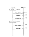
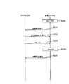
図3に示すように、ステップ110において、PV-PCS220は、電力系統の電圧値Vacが所定系統電圧閾値Vthを超えたことを検出する。
図3に示すように、ステップ110において、PV-PCS220は、電力系統の電圧値Vacが所定系統電圧閾値Vthを超えたことを検出する。
ステップ111において、PV-PCS220は、蓄電池213(又は、EV214)の充電開始を指示する充電モード移行指示を蓄電PCS240に送信する。また、蓄電PCS240は、充電モード移行指示に応じて、蓄電池213(又は、EV214)の充電を開始する。
ステップ112において、蓄電PCS240は、蓄電池213(又は、EV214)の充電を開始した旨(充電開始通知)をPV-PCS220に送信する。
ステップ113において、PV-PCS220は、PV-PCS220の出力抑制を停止した旨を示す出力抑制停止通知を蓄電PCS240に送信する。ここでは、電力系統の電圧値Vacが所定系統電圧閾値Vthを超えているため、PV-PCS220は、自律的に出力を抑制しているが、充電開始通知に応じて、出力抑制を停止することを前提としていることに留意すべきである。従って、このような前提が存在しなければ、ステップ113の処理は省略されてもよい。
ステップ114において、PV-PCS220は、PV211の発電量(Vpv、Ipv)を蓄電PCS240に送信する。また、PV-PCS220は、電力系統の電力値(Vac、Iac)を蓄電PCS240に送信する。
なお、Vpvは、PV211によって発電される電力の電圧値であり、Ipvは、PV211によって発電される電力の電流値である。また、Vacは、電力系統の電圧値であり、Iacは、電力系統の電流値である。
ここで、PV-PCS220は、PV211の発電量(Vpv、Ipv)及び電力系統の電力値(Vac、Iac)を周期的に送信することに留意すべきである。
ステップ115において、蓄電PCS240は、蓄電池213(又は、EV214)の蓄電量(Vbatt、Ibatt)をPV-PCS220に送信する。
なお、Vbattは、蓄電池213(又は、EV214)に蓄電される電力の電圧値であり、Ibattは、蓄電池213(又は、EV214)に蓄電される電力の電流値である。
ここで、蓄電PCS240は、蓄電池213(又は、EV214)の蓄電量(Vbatt、Ibatt)を周期的に送信することに留意すべきである。
ステップ116において、PV-PCS220は、電力系統の電圧値Vacが所定系統電圧閾値Vthを下回ったことを検出する。
ステップ117において、PV-PCS220は、蓄電池213(又は、EV214)の充電停止を指示する充電モード解除指示を蓄電PCS240に送信する。また、蓄電PCS240は、充電モード停止指示に応じて、蓄電池213(又は、EV214)の充電を停止する。
ステップ118において、蓄電PCS240は、蓄電池213(又は、EV214)の充電を停止した旨(充電停止通知)をPV-PCS220に送信する。
(1-2)蓄電量に応じて充電を解除するケース
図4に示すように、ステップ120~ステップ125の処理は、ステップ110~ステップ115の処理と同様である。従って、ステップ120~ステップ125の説明については省略する。
図4に示すように、ステップ120~ステップ125の処理は、ステップ110~ステップ115の処理と同様である。従って、ステップ120~ステップ125の説明については省略する。
ステップ126において、PV-PCS220は、蓄電池213(又は、EV214)の蓄電量が所定蓄電量を超えたことを検出する。ここでは、PV-PCS220は、蓄電池213(又は、EV214)の蓄電量Pbattが満充電蓄電量fullに達したことを検出する。
ここで、PV-PCS220は、蓄電池213(又は、EV214)の蓄電量の電圧値が所定閾値を超えたことを検出してもよい。或いは、PV-PCS220は、蓄電池213(又は、EV214)の蓄電量の電流値が所定閾値を超えたことを検出してもよい。
なお、ステップ127~ステップ128の処理は、ステップ117~ステップ118の処理と同様である。従って、ステップ127~ステップ128の説明については省略する。
(1-3)発電量に応じて充電を解除するケース
図5に示すように、ステップ130~ステップ133の処理は、ステップ110~ステップ113の処理と同様である。従って、ステップ120~ステップ130の説明については省略する。
図5に示すように、ステップ130~ステップ133の処理は、ステップ110~ステップ113の処理と同様である。従って、ステップ120~ステップ130の説明については省略する。
ステップ134において、PV-PCS220は、PV211の発電量が所定発電量を下回ったことを検出する。ここでは、PV-PCS220は、PV211の発電量Ppvが略ゼロになったことを検出する。
ここで、PV-PCS220は、PV211の発電電力の電圧値が所定閾値を下回ったことを検出してもよい。或いは、PV-PCS220は、PV211の発電電力の電流値が所定閾値を下回ったことを検出してもよい。
なお、ステップ135~ステップ136の処理は、ステップ117~ステップ118の処理と同様である。従って、ステップ135~ステップ136の説明については省略する。
第2に、蓄電PCS240が制御部を構成するケースについて、図6~図8を参照しながら説明する。
(2-1)系統電圧値に応じて充電を解除するケース
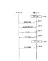
図6に示すように、ステップ210において、蓄電PCS240は、電力系統の電圧値Vacが所定系統電圧閾値Vthを超えたことを検出する。また、蓄電PCS240は、蓄電池213(又は、EV214)の充電を開始する。
図6に示すように、ステップ210において、蓄電PCS240は、電力系統の電圧値Vacが所定系統電圧閾値Vthを超えたことを検出する。また、蓄電PCS240は、蓄電池213(又は、EV214)の充電を開始する。
ステップ211において、蓄電PCS240は、蓄電池213(又は、EV214)の充電を開始した旨(充電開始通知)をPV-PCS220に送信する。
ステップ212において、PV-PCS220は、PV-PCS220の出力抑制を停止した旨を示す出力抑制停止通知を蓄電PCS240に送信する。
ステップ213において、PV-PCS220は、PV211の発電量(Vpv、Ipv)を蓄電PCS240に送信する。ここで、PV-PCS220は、PV211の発電量(Vpv、Ipv)を周期的に送信することに留意すべきである。
ステップ214において、蓄電PCS240は、蓄電池213(又は、EV214)の蓄電量(Vbatt、Ibatt)をPV-PCS220に送信する。ここで、蓄電PCS240は、蓄電池213(又は、EV214)の蓄電量(Vbatt、Ibatt)を周期的に送信することに留意すべきである。
ステップ215において、蓄電PCS240は、電力系統の電圧値Vac’が所定系統電圧閾値Vth’を下回ったことを検出する。また、蓄電PCS240は、蓄電池213(又は、EV214)の充電を停止する。
ステップ216において、蓄電PCS240は、蓄電池213(又は、EV214)の充電を停止した旨(充電停止通知)をPV-PCS220に送信する。
(2-2)蓄電量に応じて充電を解除するケース
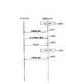
図7に示すように、ステップ220~ステップ223の処理は、ステップ210~ステップ213の処理と同様である。従って、ステップ220~ステップ223の説明については省略する。
図7に示すように、ステップ220~ステップ223の処理は、ステップ210~ステップ213の処理と同様である。従って、ステップ220~ステップ223の説明については省略する。
ステップ224において、蓄電PCS240は、蓄電池213(又は、EV214)の蓄電量が所定蓄電量を超えたことを検出する。ここでは、蓄電PCS240は、蓄電池213(又は、EV214)の蓄電量Pbattが満充電蓄電量fullに達したことを検出する。また、蓄電PCS240は、蓄電池213(又は、EV214)の充電を停止する。
ここで、蓄電PCS240は、蓄電池213(又は、EV214)の蓄電量の電圧値が所定閾値を超えたことを検出してもよい。或いは、蓄電PCS240は、蓄電池213(又は、EV214)の蓄電量の電流値が所定閾値を超えたことを検出してもよい。
なお、ステップ225の処理は、ステップ216の処理と同様である。従って、ステップ225の説明については省略する。
(2-3)発電量に応じて充電を解除するケース
図8に示すように、ステップ230~ステップ233の処理は、ステップ210~ステップ213の処理と同様である。従って、ステップ230~ステップ233の説明については省略する。
図8に示すように、ステップ230~ステップ233の処理は、ステップ210~ステップ213の処理と同様である。従って、ステップ230~ステップ233の説明については省略する。
ステップ234において、蓄電PCS240は、PV211の発電量が所定発電量を下回ったことを検出する。ここでは、蓄電PCS240は、PV211の発電量Ppvが略ゼロになったことを検出する。また、蓄電PCS240は、蓄電池213(又は、EV214)の充電を停止する。
ここで、蓄電PCS240は、PV211の発電電力の電圧値が所定閾値を下回ったことを検出してもよい。或いは、蓄電PCS240は、PV211の発電電力の電流値が所定閾値を下回ったことを検出してもよい。
なお、ステップ235の処理は、ステップ216の処理と同様である。従って、ステップ235の説明については省略する。
(作用及び効果)
第1実施形態では、制御部(PV-PCS220又は蓄電PCS240)は、電力系統の電圧値が所定系統電圧閾値を超えた場合に、蓄電池(蓄電池213又はEV214)の充電を開始するように、蓄電池の動作モードを制御する。従って、発電装置(PV211)によって発電された電力が電力系統を経由して蓄電池に供給されるケースでは、電力系統に接続される負荷が増大し、電力系統の電圧値の上昇が抑制される。発電装置によって発電された電力が電力系統を経由せずに蓄電池に供給されるケースでは、電力系統の電圧値に影響を与えることなく、発電装置によって発電された電力が利用される。これによって、発電装置の発電能力を活かすことが可能である。
第1実施形態では、制御部(PV-PCS220又は蓄電PCS240)は、電力系統の電圧値が所定系統電圧閾値を超えた場合に、蓄電池(蓄電池213又はEV214)の充電を開始するように、蓄電池の動作モードを制御する。従って、発電装置(PV211)によって発電された電力が電力系統を経由して蓄電池に供給されるケースでは、電力系統に接続される負荷が増大し、電力系統の電圧値の上昇が抑制される。発電装置によって発電された電力が電力系統を経由せずに蓄電池に供給されるケースでは、電力系統の電圧値に影響を与えることなく、発電装置によって発電された電力が利用される。これによって、発電装置の発電能力を活かすことが可能である。
[その他の実施形態]
本発明は上述した実施形態によって説明したが、この開示の一部をなす論述及び図面は、この発明を限定するものであると理解すべきではない。この開示から当業者には様々な代替実施形態、実施例及び運用技術が明らかとなろう。
本発明は上述した実施形態によって説明したが、この開示の一部をなす論述及び図面は、この発明を限定するものであると理解すべきではない。この開示から当業者には様々な代替実施形態、実施例及び運用技術が明らかとなろう。
実施形態では、PV211及び蓄電池213(又は、EV214)は、別々のPCSによって制御される。しかしながら、PV211及び蓄電池213(又は、EV214)は、1つのPCS(いわゆるハイブリッドPCS)によって制御されてもよい。
実施形態では、発電装置として、PV211を例に挙げて説明した。しかしながら、発電装置は、SOFC212であってもよい。このようなケースでは、SOFC-PCS230が制御部を構成する。或いは、発電装置は、風力発電装置、水力発電装置などあってもよい。このようなケースでは、発電装置を制御するPCSが制御部を構成する。
実施形態では、PV211によって発電された電力が電力系統を経由せずに蓄電池213(又は、EV214)に直接的に供給されるケースにおいて、PV211によって発電された電力が交流電力に変換された上で、交流電力に変換された電力が再び直流電力に変換される。しかしながら、PV211によって発電された電力が購入電力に変換されずに蓄電池213(又は、EV214)に供給されてもよい。
実施形態では、蓄電池213(又は、EV214)の動作モードを制御する単位として、需要家10を例に挙げて説明した。しかしながら、実施形態は、これに限定されるものではない。例えば、蓄電池213(又は、EV214)の動作モードを制御する単位は、複数の需要家10であってもよい。このようなケースでは、上述したEMS20やスマートサーバ40が制御部を構成する。
実施形態では、通信線の詳細について特に触れていないが、通信線は、有線であってもよく、無線であってもよい。
実施形態では、蓄電量の詳細について特に触れていないが、蓄電量は、電流、電圧、電力、単位時間当たりの電力、又は、単位時間当たりの電流のいずれかによって示される値であってもよい。
なお、日本国特許出願第2011-164488号(2011年7月27日出願)の全内容が、参照により、本願明細書に組み込まれている。
本発明によれば、発電装置の発電能力を活かすことを可能とする電力管理システムを提供することができる。
Claims (8)
- 電力を発電する発電装置と、電力を蓄積する蓄電池とを備えており、電力系統に接続された電力管理システムであって、
前記電力系統の電圧値が所定系統電圧閾値を超えた場合に、前記蓄電池の充電を開始するように、前記蓄電池の動作モードを制御する制御部を備えることを特徴とする電力管理システム。 - 前記制御部は、前記電力系統の電圧値が前記所定系統電圧閾値を超えた場合に、前記電力系統を経由せずに、前記発電装置から供給される電力が前記蓄電池に直接的に供給されるように、前記発電装置と前記蓄電池との接続を制御することを特徴とする請求項1に記載の電力管理システム。
- 前記蓄電池を制御する第1制御部を備え、
前記第1制御部は、前記電力系統の電圧値が前記所定系統電圧閾値を超えたか否かを検出し、前記制御部を構成することを特徴とする請求項1に記載の電力管理システム。 - 前記発電装置を制御する第2制御部を備え、
前記第2制御部は、前記電力系統の電圧値が前記所定系統電圧閾値を超えたか否かを検出し、前記制御部を構成することを特徴とする請求項1に記載の電力管理システム。 - 前記制御部は、前記電力系統の電圧値が所定系統電圧閾値を下回った場合に、前記蓄電池の充電を停止するように、前記蓄電池の動作モードを制御することを特徴とする請求項1に記載の電力管理システム。
- 前記制御部は、前記蓄電池の蓄電量が所定蓄電量を超えた場合に、前記蓄電池の充電を停止するように、前記蓄電池の動作モードを制御することを特徴とする請求項1に記載の電力管理システム。
- 前記制御部は、前記発電装置の発電量が所定発電量を下回った場合に、前記蓄電池の充電を停止するように、前記蓄電池の動作モードを制御することを特徴とする請求項1に記載の電力管理システム。
- 電力を発電する発電装置と、電力を蓄積する蓄電池とを備えており、電力系統に接続された電力管理システムで用いる電力管理方法あって、
前記電力系統の電圧値が所定系統電圧閾値を超えた場合に、前記蓄電池の充電を開始するように、前記蓄電池の動作モードを制御するステップを備えることを特徴とする電力管理方法。
Priority Applications (3)
| Application Number | Priority Date | Filing Date | Title |
|---|---|---|---|
| EP12817718.5A EP2738903A4 (en) | 2011-07-27 | 2012-07-23 | SERVICE MANAGEMENT SYSTEM AND ADMINISTRATIVE PROCEDURE |
| US14/235,213 US9509149B2 (en) | 2011-07-27 | 2012-07-23 | Power management system and management method |
| CN201280037124.6A CN103703648A (zh) | 2011-07-27 | 2012-07-23 | 电力管理系统及管理方法 |
Applications Claiming Priority (2)
| Application Number | Priority Date | Filing Date | Title |
|---|---|---|---|
| JP2011-164488 | 2011-07-27 | ||
| JP2011164488A JP5960958B2 (ja) | 2011-07-27 | 2011-07-27 | 電力管理システム |
Publications (1)
| Publication Number | Publication Date |
|---|---|
| WO2013015256A1 true WO2013015256A1 (ja) | 2013-01-31 |
Family
ID=47601102
Family Applications (1)
| Application Number | Title | Priority Date | Filing Date |
|---|---|---|---|
| PCT/JP2012/068621 Ceased WO2013015256A1 (ja) | 2011-07-27 | 2012-07-23 | 電力管理システム及び管理方法 |
Country Status (5)
| Country | Link |
|---|---|
| US (1) | US9509149B2 (ja) |
| EP (1) | EP2738903A4 (ja) |
| JP (1) | JP5960958B2 (ja) |
| CN (1) | CN103703648A (ja) |
| WO (1) | WO2013015256A1 (ja) |
Cited By (1)
| Publication number | Priority date | Publication date | Assignee | Title |
|---|---|---|---|---|
| DE112016006748T5 (de) | 2016-04-14 | 2018-12-27 | Mitsubishi Electric Corporation | Energiemanagementsystem |
Families Citing this family (15)
| Publication number | Priority date | Publication date | Assignee | Title |
|---|---|---|---|---|
| EP2763265B1 (en) * | 2011-09-28 | 2021-09-22 | Kyocera Corporation | Power conditioner system and storage battery power conditioner |
| JP6158562B2 (ja) * | 2013-04-01 | 2017-07-05 | 京セラ株式会社 | 電力変換装置、制御システム、及び制御方法 |
| CN103427430B (zh) * | 2013-04-08 | 2017-07-11 | 深圳市天智系统技术有限公司 | 一种混合储能系统在微网中的能量管理方法 |
| JP6016719B2 (ja) * | 2013-06-27 | 2016-10-26 | トヨタホーム株式会社 | 充電制御システム |
| CN103683517B (zh) * | 2013-12-19 | 2015-08-19 | 合肥工业大学 | 一种应用于微电网的混合储能系统 |
| JP6174478B2 (ja) * | 2013-12-24 | 2017-08-02 | 京セラ株式会社 | 電力制御装置、機器制御装置、及び方法 |
| JP6527681B2 (ja) * | 2014-10-09 | 2019-06-05 | シャープ株式会社 | パワーコンディショナ、その電力制御方法、及び電力制御システム |
| EP3306771B1 (en) * | 2015-06-08 | 2019-11-27 | Kyocera Corporation | Electric power conversion device, electric power management device, and electric power management method |
| CN105024391B (zh) * | 2015-07-21 | 2017-07-28 | 清华大学 | 微电网混合储能协调调频方法 |
| CN205945094U (zh) * | 2016-08-03 | 2017-02-08 | 中广核研究院有限公司 | 一种孤岛综合能源供给及保障系统 |
| WO2018097448A1 (ko) * | 2016-11-28 | 2018-05-31 | 디엔비하우징(주) | 다중연계 전력공급 시스템 |
| CN110112441B (zh) * | 2018-02-01 | 2021-03-02 | 郑州宇通客车股份有限公司 | 一种燃料电池系统的高电位控制方法及装置 |
| CN108808823B (zh) * | 2018-06-22 | 2024-01-19 | 河南森源电气股份有限公司 | 一种光伏组件自启动控制装置和一种供电系统 |
| DE102020214416A1 (de) | 2020-11-17 | 2022-05-19 | Robert Bosch Gesellschaft mit beschränkter Haftung | Verfahren zum Laden oder Entladen eines elektrochemischen Energiespeichers |
| US20220396167A1 (en) * | 2021-06-09 | 2022-12-15 | Bahman Sharifipour | Electric vehicle solar charging system |
Citations (6)
| Publication number | Priority date | Publication date | Assignee | Title |
|---|---|---|---|---|
| JPH06133472A (ja) * | 1992-10-19 | 1994-05-13 | Canon Inc | 太陽光発電システム |
| JP2004180467A (ja) * | 2002-11-29 | 2004-06-24 | Hitachi Home & Life Solutions Inc | 系統連系形電源システム |
| JP2010130836A (ja) * | 2008-11-28 | 2010-06-10 | Seiko Electric Co Ltd | 電力供給システム及び電力切替装置 |
| JP2011019315A (ja) * | 2009-07-07 | 2011-01-27 | Toshiba Corp | 情報処理装置 |
| JP2011114930A (ja) | 2009-11-26 | 2011-06-09 | Konica Minolta Holdings Inc | 系統連係型発電システム |
| JP2012139019A (ja) * | 2010-12-27 | 2012-07-19 | Noritz Corp | パワーコンディショナ |
Family Cites Families (5)
| Publication number | Priority date | Publication date | Assignee | Title |
|---|---|---|---|---|
| JP4213941B2 (ja) * | 2002-10-11 | 2009-01-28 | シャープ株式会社 | 複数の分散電源の出力抑制方法および分散電源管理システム |
| CN101127447A (zh) * | 2006-08-18 | 2008-02-20 | 鸿富锦精密工业(深圳)有限公司 | 充电电路 |
| KR101097260B1 (ko) | 2009-12-15 | 2011-12-22 | 삼성에스디아이 주식회사 | 계통 연계형 전력 저장 시스템 및 전력 저장 시스템 제어 방법 |
| ES2777887T3 (es) * | 2010-05-03 | 2020-08-06 | Siemens Gamesa Renewable Energy As | Sistema para intercambiar energía eléctrica entre una batería y una red eléctrica y procedimiento respectivo |
| KR101174891B1 (ko) * | 2010-06-01 | 2012-08-17 | 삼성에스디아이 주식회사 | 전력 저장 시스템 및 그 제어방법 |
-
2011
- 2011-07-27 JP JP2011164488A patent/JP5960958B2/ja not_active Expired - Fee Related
-
2012
- 2012-07-23 EP EP12817718.5A patent/EP2738903A4/en not_active Withdrawn
- 2012-07-23 US US14/235,213 patent/US9509149B2/en active Active
- 2012-07-23 CN CN201280037124.6A patent/CN103703648A/zh active Pending
- 2012-07-23 WO PCT/JP2012/068621 patent/WO2013015256A1/ja not_active Ceased
Patent Citations (6)
| Publication number | Priority date | Publication date | Assignee | Title |
|---|---|---|---|---|
| JPH06133472A (ja) * | 1992-10-19 | 1994-05-13 | Canon Inc | 太陽光発電システム |
| JP2004180467A (ja) * | 2002-11-29 | 2004-06-24 | Hitachi Home & Life Solutions Inc | 系統連系形電源システム |
| JP2010130836A (ja) * | 2008-11-28 | 2010-06-10 | Seiko Electric Co Ltd | 電力供給システム及び電力切替装置 |
| JP2011019315A (ja) * | 2009-07-07 | 2011-01-27 | Toshiba Corp | 情報処理装置 |
| JP2011114930A (ja) | 2009-11-26 | 2011-06-09 | Konica Minolta Holdings Inc | 系統連係型発電システム |
| JP2012139019A (ja) * | 2010-12-27 | 2012-07-19 | Noritz Corp | パワーコンディショナ |
Non-Patent Citations (1)
| Title |
|---|
| See also references of EP2738903A4 |
Cited By (2)
| Publication number | Priority date | Publication date | Assignee | Title |
|---|---|---|---|---|
| DE112016006748T5 (de) | 2016-04-14 | 2018-12-27 | Mitsubishi Electric Corporation | Energiemanagementsystem |
| US10749346B2 (en) | 2016-04-14 | 2020-08-18 | Mitsubishi Electric Corporation | Power management system |
Also Published As
| Publication number | Publication date |
|---|---|
| CN103703648A (zh) | 2014-04-02 |
| JP2013031266A (ja) | 2013-02-07 |
| EP2738903A4 (en) | 2015-08-12 |
| US9509149B2 (en) | 2016-11-29 |
| US20140183945A1 (en) | 2014-07-03 |
| JP5960958B2 (ja) | 2016-08-02 |
| EP2738903A1 (en) | 2014-06-04 |
Similar Documents
| Publication | Publication Date | Title |
|---|---|---|
| JP5960958B2 (ja) | 電力管理システム | |
| KR101146670B1 (ko) | 에너지 관리 시스템 및 이의 제어 방법 | |
| US8803362B2 (en) | Standalone unit of a standalone power grid for communicating energy requests with another standalone unit | |
| US8946933B2 (en) | Power management apparatus and method of operating the same | |
| CN102237689A (zh) | 在电池和电网之间交换电能的电力交换系统和方法及应用 | |
| US20160329744A1 (en) | Power control device and power control method | |
| WO2011042781A1 (ja) | 電力供給システム | |
| WO2015001800A1 (ja) | マイクログリッドの制御装置及びその制御方法 | |
| JP2015192566A (ja) | 電力システム及び直流送電方法 | |
| WO2014024870A1 (ja) | 管理方法、制御装置及び蓄電装置 | |
| WO2014003037A1 (ja) | 制御装置、燃料電池ユニット及び制御方法 | |
| KR20150085227A (ko) | 에너지 저장 시스템 및 그의 제어 방법 | |
| WO2014024839A1 (ja) | 管理システム、管理方法、制御装置及び発電装置 | |
| WO2014024840A1 (ja) | 管理システム、管理方法、制御装置及び発電装置 | |
| JP5922525B2 (ja) | 制御装置、燃料電池システム及び制御方法 | |
| US12407169B2 (en) | Energy coupling method and system for household energy storage | |
| US20250167586A1 (en) | Energy coupling method and system for household energy storage | |
| JP5912070B2 (ja) | 制御装置、燃料電池システム及び制御方法 | |
| CN106230006A (zh) | 微电网控制方法和装置及微电网 | |
| JP2016032379A (ja) | 電力供給システム | |
| JP5872353B2 (ja) | エネルギー管理システム及びエネルギー管理方法 | |
| JP5922524B2 (ja) | 制御装置、燃料電池ユニット及び制御方法 | |
| JP5902062B2 (ja) | 制御装置、燃料電池システム及び制御方法 | |
| KR102333046B1 (ko) | 에너지 저장장치(ess)의 충방전량 제어 장치 및 제어 방법 |
Legal Events
| Date | Code | Title | Description |
|---|---|---|---|
| 121 | Ep: the epo has been informed by wipo that ep was designated in this application |
Ref document number: 12817718 Country of ref document: EP Kind code of ref document: A1 |
|
| NENP | Non-entry into the national phase |
Ref country code: DE |
|
| WWE | Wipo information: entry into national phase |
Ref document number: 14235213 Country of ref document: US |
|
| WWE | Wipo information: entry into national phase |
Ref document number: 2012817718 Country of ref document: EP |