WO2013015256A1 - Système et procédé de gestion d'énergie électrique - Google Patents
Système et procédé de gestion d'énergie électrique Download PDFInfo
- Publication number
- WO2013015256A1 WO2013015256A1 PCT/JP2012/068621 JP2012068621W WO2013015256A1 WO 2013015256 A1 WO2013015256 A1 WO 2013015256A1 JP 2012068621 W JP2012068621 W JP 2012068621W WO 2013015256 A1 WO2013015256 A1 WO 2013015256A1
- Authority
- WO
- WIPO (PCT)
- Prior art keywords
- power
- storage battery
- pcs
- storage
- predetermined
- Prior art date
- Legal status (The legal status is an assumption and is not a legal conclusion. Google has not performed a legal analysis and makes no representation as to the accuracy of the status listed.)
- Ceased
Links
Images


Classifications
-
- H—ELECTRICITY
- H02—GENERATION; CONVERSION OR DISTRIBUTION OF ELECTRIC POWER
- H02J—ELECTRIC POWER NETWORKS; CIRCUIT ARRANGEMENTS OR SYSTEMS FOR SUPPLYING OR DISTRIBUTING ELECTRIC POWER; SYSTEMS FOR STORING ELECTRIC ENERGY
- H02J3/00—Circuit arrangements for AC mains or AC distribution networks
- H02J3/28—Arrangements for balancing of the load in networks by storage of energy
- H02J3/32—Arrangements for balancing of the load in networks by storage of energy using batteries or super capacitors with converting means
-
- H—ELECTRICITY
- H02—GENERATION; CONVERSION OR DISTRIBUTION OF ELECTRIC POWER
- H02J—ELECTRIC POWER NETWORKS; CIRCUIT ARRANGEMENTS OR SYSTEMS FOR SUPPLYING OR DISTRIBUTING ELECTRIC POWER; SYSTEMS FOR STORING ELECTRIC ENERGY
- H02J3/00—Circuit arrangements for AC mains or AC distribution networks
-
- H—ELECTRICITY
- H02—GENERATION; CONVERSION OR DISTRIBUTION OF ELECTRIC POWER
- H02J—ELECTRIC POWER NETWORKS; CIRCUIT ARRANGEMENTS OR SYSTEMS FOR SUPPLYING OR DISTRIBUTING ELECTRIC POWER; SYSTEMS FOR STORING ELECTRIC ENERGY
- H02J3/00—Circuit arrangements for AC mains or AC distribution networks
- H02J3/38—Arrangements for feeding a single network from two or more generators or sources in parallel; Arrangements for feeding already energised networks from additional generators or sources in parallel
- H02J3/381—Dispersed generators
-
- H—ELECTRICITY
- H02—GENERATION; CONVERSION OR DISTRIBUTION OF ELECTRIC POWER
- H02J—ELECTRIC POWER NETWORKS; CIRCUIT ARRANGEMENTS OR SYSTEMS FOR SUPPLYING OR DISTRIBUTING ELECTRIC POWER; SYSTEMS FOR STORING ELECTRIC ENERGY
- H02J7/00—Circuit arrangements for charging or discharging batteries or for supplying loads from batteries
-
- H—ELECTRICITY
- H02—GENERATION; CONVERSION OR DISTRIBUTION OF ELECTRIC POWER
- H02J—ELECTRIC POWER NETWORKS; CIRCUIT ARRANGEMENTS OR SYSTEMS FOR SUPPLYING OR DISTRIBUTING ELECTRIC POWER; SYSTEMS FOR STORING ELECTRIC ENERGY
- H02J2101/00—Supply or distribution of decentralised, dispersed or local electric power generation
- H02J2101/20—Dispersed power generation using renewable energy sources
- H02J2101/22—Solar energy
- H02J2101/24—Photovoltaics
-
- Y—GENERAL TAGGING OF NEW TECHNOLOGICAL DEVELOPMENTS; GENERAL TAGGING OF CROSS-SECTIONAL TECHNOLOGIES SPANNING OVER SEVERAL SECTIONS OF THE IPC; TECHNICAL SUBJECTS COVERED BY FORMER USPC CROSS-REFERENCE ART COLLECTIONS [XRACs] AND DIGESTS
- Y02—TECHNOLOGIES OR APPLICATIONS FOR MITIGATION OR ADAPTATION AGAINST CLIMATE CHANGE
- Y02E—REDUCTION OF GREENHOUSE GAS [GHG] EMISSIONS, RELATED TO ENERGY GENERATION, TRANSMISSION OR DISTRIBUTION
- Y02E10/00—Energy generation through renewable energy sources
- Y02E10/50—Photovoltaic [PV] energy
- Y02E10/56—Power conversion systems, e.g. maximum power point trackers
-
- Y—GENERAL TAGGING OF NEW TECHNOLOGICAL DEVELOPMENTS; GENERAL TAGGING OF CROSS-SECTIONAL TECHNOLOGIES SPANNING OVER SEVERAL SECTIONS OF THE IPC; TECHNICAL SUBJECTS COVERED BY FORMER USPC CROSS-REFERENCE ART COLLECTIONS [XRACs] AND DIGESTS
- Y02—TECHNOLOGIES OR APPLICATIONS FOR MITIGATION OR ADAPTATION AGAINST CLIMATE CHANGE
- Y02E—REDUCTION OF GREENHOUSE GAS [GHG] EMISSIONS, RELATED TO ENERGY GENERATION, TRANSMISSION OR DISTRIBUTION
- Y02E70/00—Other energy conversion or management systems reducing GHG emissions
- Y02E70/30—Systems combining energy storage with energy generation of non-fossil origin
Definitions
- the present invention relates to a power management system and a management method including a power generation device and a storage battery.
- EMS Energy Management System
- Such EMS performs control (reverse power flow control) or the like that outputs supply power supplied by the power generator to the power system (for example, Patent Document 1).
- the voltage value of the power system increases.
- the voltage value of the power system reaches the allowable voltage value so that the voltage value of the power system exceeds the allowable voltage value allowed for the power system and power is not output to the power system, the power output by the power generator to the power system (Reverse power flow) is suppressed.
- the power (reverse power flow) output from the power generator to the power system is suppressed.
- the power generation device is a device that generates electric power using natural energy
- the utilization efficiency of natural energy decreases.
- the follow-up of the power generation amount is not excellent, the power generated by the power generation device is wasted.
- the power management system includes a power generation device that generates electric power and a storage battery that stores electric power, and is connected to an electric power system.
- the power management system includes a control unit that controls an operation mode of the storage battery so that charging of the storage battery is started when a voltage value of the power system exceeds a predetermined system voltage threshold.
- the control unit When the voltage value of the power system exceeds the predetermined system voltage threshold value, the control unit directly supplies power supplied from the power generation device to the storage battery without passing through the power system. Thus, the connection between the power generation device and the storage battery is controlled.
- the power management system includes a first control unit that controls the storage battery.
- the first control unit detects whether a voltage value of the power system exceeds the predetermined system voltage threshold value, and configures the control unit.
- the power management system includes a second control unit that controls the power generation device.
- the second control unit detects whether the voltage value of the power system exceeds the predetermined system voltage threshold value, and configures the control unit.
- control unit controls an operation mode of the storage battery so that charging of the storage battery is stopped when a voltage value of the power system falls below a predetermined system voltage threshold.
- control unit controls an operation mode of the storage battery so that charging of the storage battery is stopped when a storage amount of the storage battery exceeds a predetermined storage amount.
- control unit controls an operation mode of the storage battery so that charging of the storage battery is stopped when a power generation amount of the power generation device falls below a predetermined power generation amount.
- the power management method includes a power generation device that generates power and a storage battery that stores power, and is a method used in a power management system connected to the power system.
- the power management method includes a step of controlling an operation mode of the storage battery so that charging of the storage battery is started when a voltage value of the power system exceeds a predetermined system voltage threshold.
- FIG. 1 is a diagram illustrating an outline of a power management system according to the first embodiment.
- FIG. 2 is a diagram illustrating details of the power management system according to the first embodiment.
- FIG. 3 is a diagram illustrating the operation of the power management system according to the first embodiment.
- FIG. 4 is a diagram illustrating the operation of the power management system according to the first embodiment.
- FIG. 5 is a diagram illustrating the operation of the power management system according to the first embodiment.
- FIG. 6 is a diagram illustrating the operation of the power management system according to the first embodiment.
- FIG. 7 is a diagram illustrating the operation of the power management system according to the first embodiment.
- FIG. 8 is a diagram illustrating the operation of the power management system according to the first embodiment.
- the power management system includes a power generation device that generates power and a storage battery that stores the power, and is connected to the power system.
- the power management system includes a control unit that controls an operation mode of the storage battery so that charging of the storage battery is started when the voltage value of the power system exceeds a predetermined system voltage threshold.
- the predetermined system voltage threshold value may be an allowable voltage value or a value obtained by subtracting a predetermined margin from the allowable voltage value.
- the control unit controls the operation mode of the storage battery so that charging of the storage battery is started when the voltage value of the power system exceeds a predetermined system voltage threshold. Therefore, in the case where the electric power generated by the power generation device is supplied to the storage battery via the power system, the load connected to the power system increases, and the increase in the voltage value of the power system is suppressed. In the case where the power generated by the power generation device is supplied to the storage battery without going through the power system, the power generated by the power generation device is used without affecting the voltage value of the power system. Thereby, it is possible to make use of the power generation capability of the power generation device.
- the power generation device is a solar cell, a wind power generation device, a hydroelectric power generation device, or the like that uses natural energy.
- the power generation device is a fuel cell that uses fuel such as gas.
- the storage battery may be a battery provided in EV (Electric Vehicle).
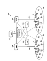
- FIG. 1 is a diagram illustrating an outline of a power management system 100 according to the first embodiment.
- the power management system 100 includes a customer 10, an EMS 20, a substation 30, a smart server 40, and a power plant 50.
- the customer 10, the EMS 20, the substation 30 and the smart server 40 are connected by a network 60.
- Customer 10 has a distributed power source such as a solar battery. Further, the customer 10 may have other power supply means such as a storage battery as a distributed power source.
- the consumer 10 may be a single-family house, an apartment house such as a condominium, a commercial facility such as a building, or a factory.
- a plurality of consumers 10 constitutes a customer group 10A and a customer group 10B.
- the consumer group 10A and the consumer group 10B are classified by, for example, a geographical area.
- the EMS20 controls the interconnection between the some customer 10 and an electric power grid
- the EMS 20 may be referred to as a CEMS (Cluster Energy Management System) in order to manage a plurality of consumers 10. Specifically, the EMS 20 disconnects between the plurality of consumers 10 and the power system at the time of a power failure or the like. On the other hand, the EMS 20 interconnects the plurality of consumers 10 and the power system when power is restored.
- CEMS Cluster Energy Management System
- the EMS 20A and EMS 20B are provided in the first embodiment.
- the EMS 20A controls, for example, interconnection between the customer 10 included in the customer group 10A and the power system.
- the EMS 20B controls interconnection between the customer 10 included in the customer group 10B and the power system.
- the substation 30 supplies power to the plurality of consumers 10 via the distribution line 31. Specifically, the substation 30 steps down the voltage supplied from the power plant 50.
- a substation 30A and a substation 30B are provided.
- the substation 30A supplies power to the consumers 10 included in the consumer group 10A via the distribution line 31A.
- the substation 30B supplies power to the consumers 10 included in the customer group 10B via the distribution line 31B.
- the smart server 40 manages a plurality of EMSs 20 (here, EMS 20A and EMS 20B).
- the smart server 40 also manages a plurality of substations 30 (here, the substation 30A and the substation 30B).
- the smart server 40 comprehensively manages the customers 10 included in the customer group 10A and the customer group 10B.
- the smart server 40 has a function of balancing the power to be supplied to the consumer group 10A and the power to be supplied to the consumer group 10B.
- the power plant 50 generates power using thermal power, wind power, hydraulic power, nuclear power, and the like.
- the power plant 50 supplies power to the plurality of substations 30 (here, the substation 30A and the substation 30B) via the power transmission line 51.
- FIG. 2 is a diagram illustrating details of the power management system 100 according to the first embodiment.
- the above-described consumer 10 will be described as an example.
- the power management system 100 includes a solar cell 211 (hereinafter referred to as PV211), a fuel cell 212 (hereinafter referred to as SOFC212), a storage battery 213, an electric vehicle 214 (hereinafter referred to as EV214), and a PV-PCS220. And an SOFC-PCS 230, a power storage PCS 240, a charger 250, a transmission / reception unit 260, and a display unit 270.
- PV211 solar cell 211
- SOFC212 fuel cell 212
- EV214 electric vehicle 214
- PV-PCS220 an electric vehicle 214
- PV211 is an example of a power generator that generates electric power. Specifically, the PV 211 generates electric power using natural energy (sunlight).
- the SOFC 212 is an example of a power generation device that generates electric power. Specifically, the SOFC 212 generates electric power using a fuel such as hydrogen or natural gas. It should be noted that a certain period of time is required after the instruction to change the power generation amount of the SOFC 212 is made until the power generation amount of the SOFC 212 is actually changed. In other words, the follow-up of the power generation amount of the SOFC 212 is not excellent.
- the storage battery 213 is a device that stores electric power.
- the EV 214 includes a battery that stores electric power. That is, the storage battery 213 and the EV 214 are examples of storage batteries that store electric power.
- the PV-PCS 220 is a device (Power Conditioning System) that controls the PV 211.
- the PV-PCS 220 includes a DC / DC 221 and an inverter DC / AC 222.
- DC / DC 221 is connected to PV 211 and inverter DC / AC 222.
- the DC / DC 221 boosts the voltage of power output from the PV 211.
- the inverter DC / AC 222 is connected to the DC / DC 221 and is connected to the power system (distribution line 31) or the power storage PCS 240 via a switch (not shown).
- the inverter DC / AC 222 converts the DC power supplied from the DC / DC 221 into AC power.
- inverter DC / AC 222 is connected to the power system.
- inverter DC / AC 222 is connected to power storage PCS 240.
- the SOFC-PCS 230 is a device (Power Conditioning System) that controls the SOFC 212.
- the SOFC-PCS 230 includes a DC / DC 231, a DC / DC 232, an inverter DC / AC 233, and an AC / DC 234.
- DC / DC 231 is connected to SOFC 212 and inverter DC / AC 233.
- the DC / DC 231 boosts the voltage of power output from the SOFC 212.
- the DC / DC 232 is connected to the SOFC 212, and the power generated by the SOFC 212 is stepped down and supplied to the control power source.
- the AC / DC 234 is connected to the DC / DC 232 and the power storage PCS 240, converts AC power supplied from the power storage PCS 240 into DC power, and is supplied to the control power source.
- the power generated by the DC / DC 232 is used as startup power for the SOFC 212.
- the inverter DC / AC 233 is connected to the DC / DC 231 and the power system (distribution line 31).
- the inverter DC / AC 233 converts the DC power supplied from the DC / DC 231 into AC power.
- the power storage PCS 240 is a device (Power Conditioning System) that controls the storage battery 213.
- the power storage PCS 240 includes an insulating DC / DC 241, a bidirectional inverter 242, a bidirectional DC / DC 243, and a relay 244 (hereinafter referred to as RY244).
- the insulated DC / DC 241 is connected to the SOFC 212 and the bidirectional DC / DC 243.
- the isolated DC / DC 241 boosts the voltage of the power supplied from the SOFC 212.
- the bidirectional inverter 242 is connected to the isolated DC / DC 241, PV-PCS 220, power system (distribution line 31), and specific load.
- the bidirectional inverter 242 converts the DC power supplied from the isolated DC / DC 241 into AC power.
- the bidirectional inverter 242 converts AC power supplied from the PV-PCS 220 or the power system into DC power.
- the specific load is a load that is connected to the power system via an internal relay in a normal time, and that operates by AC power supplied by the bidirectional inverter 242 during a power failure.
- the bidirectional DC / DC 243 is connected to the insulated DC / DC 241 and the bidirectional inverter 242, and is connected to the storage battery 213 via the RY244.
- the bidirectional DC / DC 243 steps down the voltage of the power supplied from the isolated DC / DC 241 or the bidirectional inverter 242.
- the bidirectional DC / DC 243 boosts the voltage of power supplied from the storage battery 213.
- RY244 is connected to the storage battery 213 and is connected to the EV 214 via the charger 250.
- the RY 244 switches between supplying electric power supplied from the bidirectional DC / DC 243 to the storage battery 213 or supplying electric power supplied from the bidirectional DC / DC 243 to the EV 214 via the charger 250.
- Charger 250 controls charging of a battery provided in EV 214.
- the charger 250 includes a connector for connecting to the EV 214.
- the transmission / reception unit 260 is connected to the power storage PCS 240 and operates with the power stored in the storage battery 213 (or EV 214).
- the transmission / reception unit 260 is connected to a communication line, and receives information from the PV-PCS 220, the SOFC-PCS 230, the power storage PCS 240, and the charger 250.
- the transmission / reception unit 260 is connected to a communication line and transmits information to the PV-PCS 220, the SOFC-PCS 230, the power storage PCS 240, and the charger 250.
- the transmission / reception part 260 is connected to the display part 270 by radio
- Display unit 270 is connected to power storage PCS 240 and operates with the power stored in storage battery 213 (or EV 214). Display unit 270 displays information received from transmission / reception unit 260.
- the PV-PCS 220 or the power storage PCS 240 constitutes a control unit that controls the operation mode of the storage battery 213 (or EV 214).
- the PV-PCS 220 constitutes a control unit
- the PV-PCS 220 has a function of monitoring the voltage value of the power system, and the voltage value of the power system exceeds the predetermined system voltage threshold. It is detected whether or not.
- PV-PCS 220 controls the operation mode of storage battery 213 (or EV 214) so that charging of storage battery 213 (or EV 214) is started when the voltage value of the power system exceeds a predetermined system voltage threshold. Specifically, PV-PCS 220 transmits a charge mode transition instruction to power storage PCS 240 via the communication line.
- the predetermined system voltage threshold value may be an allowable voltage value or a value obtained by subtracting a predetermined margin from the allowable voltage value.
- the PV-PCS 220 controls the operation mode of the storage battery 213 (or EV 214) so that charging of the storage battery 213 (or EV 214) is stopped when the voltage value of the power system falls below a predetermined system voltage threshold. Specifically, PV-PCS 220 transmits a charge mode release instruction to power storage PCS 240 via the communication line.
- the predetermined system voltage threshold for starting charging and the predetermined system voltage threshold for stopping charging may be different from each other.
- the predetermined system voltage threshold value for starting charging may be higher than the predetermined system voltage threshold value for stopping charging.
- the PV-PCS 220 controls the operation mode of the storage battery 213 (or EV 214) when the storage amount of the storage battery 213 (or EV 214) exceeds a predetermined storage amount. Specifically, PV-PCS 220 transmits a charge mode release instruction to power storage PCS 240 via the communication line.
- the predetermined storage amount is determined according to the storage amount (full charge storage amount) when the storage battery 213 (or EV 214) is fully charged.
- the predetermined charged amount may be a fully charged charged amount or a value obtained by subtracting a predetermined margin from the fully charged charged amount.
- the PV-PCS 220 controls the operation mode of the storage battery 213 (or EV 214) when the power generation amount of the PV 211 falls below a predetermined power generation amount. Specifically, PV-PCS 220 transmits a charge mode release instruction to power storage PCS 240 via the communication line.
- the predetermined power generation amount can be arbitrarily determined.
- the predetermined power generation amount is a power generation amount at a level at which power necessary for charging cannot be supplied.
- the power storage PCS 240 when the power storage PCS 240 forms a control unit, the power storage PCS 240 has a function of monitoring the voltage value of the power system, and whether or not the voltage value of the power system exceeds the predetermined system voltage threshold value. To detect.
- the power storage PCS 240 controls the operation mode of the storage battery 213 (or EV 214) so that charging of the storage battery 213 (or EV 214) is started when the voltage value of the power system exceeds a predetermined system voltage threshold.
- the power storage PCS 240 controls the operation mode of the storage battery 213 (or EV 214) so as to stop charging the storage battery 213 (or EV 214) when the voltage value of the power system falls below a predetermined system voltage threshold.
- the storage PCS 240 controls the operation mode of the storage battery 213 (or EV 214) when the storage amount of the storage battery 213 (or EV 214) exceeds a predetermined storage amount.
- the power storage PCS 240 controls the operation mode of the storage battery 213 (or EV 214) when the power generation amount of the PV 211 falls below a predetermined power generation amount. Specifically, the power storage PCS 240 receives the power generation amount of the PV 211 from the PV-PCS 220 via the communication line.
- the power generated by the PV 211 may be supplied to the storage battery 213 (or EV 214) via the power system.
- the electric power generated by the PV 211 may be directly supplied to the storage battery 213 (or EV 214) without going through the electric power system.
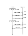
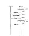
- 3 to 8 are diagrams illustrating the operation of the power management system 100 according to the first embodiment.
- PV-PCS 220 detects that the voltage value Vac of the power system exceeds a predetermined system voltage threshold Vth. To do.
- step 111 the PV-PCS 220 transmits to the power storage PCS 240 a charge mode transition instruction that instructs to start charging the storage battery 213 (or EV 214). Further, the power storage PCS 240 starts charging the storage battery 213 (or EV 214) in response to the charge mode transition instruction.
- step 112 the power storage PCS 240 transmits to the PV-PCS 220 information indicating that charging of the storage battery 213 (or EV 214) has started (charging start notification).
- step 113 the PV-PCS 220 transmits an output suppression stop notification indicating that the output suppression of the PV-PCS 220 is stopped to the power storage PCS 240.
- the PV-PCS 220 autonomously suppresses the output, but stops the output suppression in response to the charging start notification. It should be noted that Therefore, if such a premise does not exist, the process of step 113 may be omitted.
- the PV-PCS 220 transmits the power generation amount (Vpv, Ipv) of the PV 211 to the power storage PCS 240. Further, the PV-PCS 220 transmits the power value (Vac, Iac) of the power system to the power storage PCS 240.
- Vpv is a voltage value of electric power generated by the PV 211
- Ipv is a current value of electric power generated by the PV 211
- Vac is a voltage value of the power system
- Iac is a current value of the power system.
- the PV-PCS 220 periodically transmits the power generation amount (Vpv, Ipv) of the PV 211 and the power value (Vac, Iac) of the power system.
- step 115 the power storage PCS 240 transmits the power storage amount (Vbatt, Ibatt) of the storage battery 213 (or EV 214) to the PV-PCS 220.
- Vbatt is a voltage value of power stored in the storage battery 213 (or EV 214)
- Ibatt is a current value of power stored in the storage battery 213 (or EV 214).
- the storage PCS 240 periodically transmits the storage amount (Vbatt, Ibatt) of the storage battery 213 (or EV 214).
- step 116 the PV-PCS 220 detects that the voltage value Vac of the power system has fallen below the predetermined system voltage threshold value Vth.
- step 117 the PV-PCS 220 transmits to the power storage PCS 240 a charge mode release instruction that instructs to stop charging the storage battery 213 (or EV 214).
- the power storage PCS 240 stops charging the storage battery 213 (or EV 214) in response to the charge mode stop instruction.
- step 118 the power storage PCS 240 transmits to the PV-PCS 220 information indicating that charging of the storage battery 213 (or EV 214) has been stopped (charge stop notification).
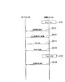
- step 120 to step 125 (1-2) Case of Canceling Charging According to Charged Capacity
- the processing from step 120 to step 125 is the same as the processing from step 110 to step 115. Therefore, the description of step 120 to step 125 is omitted.
- the PV-PCS 220 detects that the storage amount of the storage battery 213 (or EV 214) exceeds a predetermined storage amount.
- the PV-PCS 220 detects that the storage amount Pbatt of the storage battery 213 (or EV 214) has reached the full charge storage amount full.
- the PV-PCS 220 may detect that the voltage value of the storage amount of the storage battery 213 (or EV 214) has exceeded a predetermined threshold value. Alternatively, the PV-PCS 220 may detect that the current value of the storage amount of the storage battery 213 (or EV 214) exceeds a predetermined threshold value.
- step 127 to step 128 is the same as the processing from step 117 to step 118. Therefore, the description of step 127 to step 128 is omitted.
- step 130 to step 133 is the same as the processing from step 110 to step 113. Therefore, the description of steps 120 to 130 is omitted.
- step 134 the PV-PCS 220 detects that the power generation amount of the PV 211 is less than the predetermined power generation amount.
- the PV-PCS 220 detects that the power generation amount Ppv of the PV 211 has become substantially zero.
- the PV-PCS 220 may detect that the voltage value of the generated power of the PV 211 falls below a predetermined threshold value. Alternatively, the PV-PCS 220 may detect that the current value of the generated power of the PV 211 is below a predetermined threshold.
- step 135 to step 136 is the same as the processing from step 117 to step 118. Therefore, the description of step 135 to step 136 is omitted.
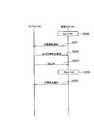
- step 210 power storage PCS 240 detects that voltage value Vac of the power system exceeds predetermined system voltage threshold value Vth. . In addition, the power storage PCS 240 starts charging the storage battery 213 (or EV 214).
- step 211 the power storage PCS 240 transmits to the PV-PCS 220 information indicating that charging of the storage battery 213 (or EV 214) has started (charging start notification).
- step 212 the PV-PCS 220 transmits an output suppression stop notification indicating that the output suppression of the PV-PCS 220 is stopped to the power storage PCS 240.
- the PV-PCS 220 transmits the power generation amount (Vpv, Ipv) of the PV 211 to the power storage PCS 240.
- the PV-PCS 220 periodically transmits the power generation amount (Vpv, Ipv) of the PV 211.
- the power storage PCS 240 transmits the power storage amount (Vbatt, Ibatt) of the storage battery 213 (or EV 214) to the PV-PCS 220.
- the storage PCS 240 periodically transmits the storage amount (Vbatt, Ibatt) of the storage battery 213 (or EV 214).
- step 215 the power storage PCS 240 detects that the voltage value Vac 'of the power system has fallen below the predetermined system voltage threshold value Vth'. In addition, the power storage PCS 240 stops charging the storage battery 213 (or EV 214).
- step 216 the power storage PCS 240 transmits to the PV-PCS 220 information indicating that charging of the storage battery 213 (or EV 214) has been stopped (charge stop notification).
- step 220 to step 223 is the same as the processing from step 210 to step 213. Therefore, the description of step 220 to step 223 is omitted.
- the power storage PCS 240 detects that the power storage amount of the storage battery 213 (or EV 214) has exceeded a predetermined power storage amount.
- the power storage PCS 240 detects that the power storage amount Pbatt of the storage battery 213 (or EV 214) has reached the full charge power storage amount full.
- the power storage PCS 240 stops charging the storage battery 213 (or EV 214).
- the power storage PCS 240 may detect that the voltage value of the power storage amount of the storage battery 213 (or EV 214) has exceeded a predetermined threshold. Alternatively, the power storage PCS 240 may detect that the current value of the power storage amount of the storage battery 213 (or EV 214) has exceeded a predetermined threshold value.
- step 225 is the same as the processing in step 216. Therefore, the description of step 225 is omitted.
- step 230 to step 233 is the same as the processing from step 210 to step 213. Therefore, the description of step 230 to step 233 is omitted.
- step 234 the power storage PCS 240 detects that the power generation amount of the PV 211 is less than the predetermined power generation amount.
- the power storage PCS 240 detects that the power generation amount Ppv of the PV 211 has become substantially zero.
- the power storage PCS 240 stops charging the storage battery 213 (or EV 214).
- the power storage PCS 240 may detect that the voltage value of the generated power of the PV 211 is below a predetermined threshold. Alternatively, the power storage PCS 240 may detect that the current value of the generated power of the PV 211 has fallen below a predetermined threshold.
- step 235 is the same as the processing in step 216. Therefore, the description of step 235 is omitted.
- the control unit causes the storage battery (storage battery 213 or EV 214) to start charging when the voltage value of the power system exceeds a predetermined system voltage threshold. Control the operation mode. Therefore, in the case where the electric power generated by the power generation device (PV211) is supplied to the storage battery via the power system, the load connected to the power system increases, and the increase in the voltage value of the power system is suppressed. In the case where the power generated by the power generation device is supplied to the storage battery without going through the power system, the power generated by the power generation device is used without affecting the voltage value of the power system. Thereby, it is possible to make use of the power generation capability of the power generation device.
- the PV 211 and the storage battery 213 are controlled by separate PCSs.
- the PV 211 and the storage battery 213 may be controlled by one PCS (so-called hybrid PCS).
- PV211 has been described as an example of the power generation device.
- the power generation device may be the SOFC 212.
- the SOFC-PCS 230 constitutes a control unit.
- the power generation device may be a wind power generation device, a hydroelectric power generation device, or the like.
- the PCS that controls the power generation device constitutes the control unit.
- the power generated by the PV 211 is converted into AC power.
- the electric power converted into AC power is converted into DC power again.
- the electric power generated by the PV 211 may be supplied to the storage battery 213 (or EV 214) without being converted into purchased electric power.
- the customer 10 is described as an example as a unit for controlling the operation mode of the storage battery 213 (or EV 214).
- the unit for controlling the operation mode of the storage battery 213 may be a plurality of consumers 10.
- the EMS 20 and the smart server 40 described above constitute a control unit.
- the communication line may be wired or wireless.
- the storage amount may be a value indicated by any of current, voltage, power, power per unit time, or current per unit time. .
- the present invention it is possible to provide a power management system that makes it possible to make use of the power generation capability of the power generation device.
Landscapes
- Engineering & Computer Science (AREA)
- Power Engineering (AREA)
- Supply And Distribution Of Alternating Current (AREA)
- Fuel Cell (AREA)
- Charge And Discharge Circuits For Batteries Or The Like (AREA)
Abstract
La présente invention concerne un système de gestion d'énergie électrique qui est connecté à un réseau électrique et est pourvu : d'un dispositif générateur qui génère de l'énergie électrique ; et d'une batterie de stockage qui accumule l'énergie électrique. Le système de gestion d'énergie électrique est pourvu d'une unité de commande qui commande le mode de fonctionnement de la batterie de stockage de manière telle à commencer la charge de la batterie de stockage lorsque la valeur de tension du réseau électrique dépasse un seuil de tension de réseau prédéterminé.
Priority Applications (3)
| Application Number | Priority Date | Filing Date | Title |
|---|---|---|---|
| EP12817718.5A EP2738903A4 (fr) | 2011-07-27 | 2012-07-23 | Système et procédé de gestion d'énergie électrique |
| US14/235,213 US9509149B2 (en) | 2011-07-27 | 2012-07-23 | Power management system and management method |
| CN201280037124.6A CN103703648A (zh) | 2011-07-27 | 2012-07-23 | 电力管理系统及管理方法 |
Applications Claiming Priority (2)
| Application Number | Priority Date | Filing Date | Title |
|---|---|---|---|
| JP2011-164488 | 2011-07-27 | ||
| JP2011164488A JP5960958B2 (ja) | 2011-07-27 | 2011-07-27 | 電力管理システム |
Publications (1)
| Publication Number | Publication Date |
|---|---|
| WO2013015256A1 true WO2013015256A1 (fr) | 2013-01-31 |
Family
ID=47601102
Family Applications (1)
| Application Number | Title | Priority Date | Filing Date |
|---|---|---|---|
| PCT/JP2012/068621 Ceased WO2013015256A1 (fr) | 2011-07-27 | 2012-07-23 | Système et procédé de gestion d'énergie électrique |
Country Status (5)
| Country | Link |
|---|---|
| US (1) | US9509149B2 (fr) |
| EP (1) | EP2738903A4 (fr) |
| JP (1) | JP5960958B2 (fr) |
| CN (1) | CN103703648A (fr) |
| WO (1) | WO2013015256A1 (fr) |
Cited By (1)
| Publication number | Priority date | Publication date | Assignee | Title |
|---|---|---|---|---|
| DE112016006748T5 (de) | 2016-04-14 | 2018-12-27 | Mitsubishi Electric Corporation | Energiemanagementsystem |
Families Citing this family (15)
| Publication number | Priority date | Publication date | Assignee | Title |
|---|---|---|---|---|
| EP2763265B1 (fr) * | 2011-09-28 | 2021-09-22 | Kyocera Corporation | Système de conditionnement de puissance et conditionneur de puissance de batterie de stockage |
| JP6158562B2 (ja) * | 2013-04-01 | 2017-07-05 | 京セラ株式会社 | 電力変換装置、制御システム、及び制御方法 |
| CN103427430B (zh) * | 2013-04-08 | 2017-07-11 | 深圳市天智系统技术有限公司 | 一种混合储能系统在微网中的能量管理方法 |
| JP6016719B2 (ja) * | 2013-06-27 | 2016-10-26 | トヨタホーム株式会社 | 充電制御システム |
| CN103683517B (zh) * | 2013-12-19 | 2015-08-19 | 合肥工业大学 | 一种应用于微电网的混合储能系统 |
| JP6174478B2 (ja) * | 2013-12-24 | 2017-08-02 | 京セラ株式会社 | 電力制御装置、機器制御装置、及び方法 |
| JP6527681B2 (ja) * | 2014-10-09 | 2019-06-05 | シャープ株式会社 | パワーコンディショナ、その電力制御方法、及び電力制御システム |
| EP3306771B1 (fr) * | 2015-06-08 | 2019-11-27 | Kyocera Corporation | Dispositif de conversion d'énergie électrique, dispositif de gestion d'énergie électrique et procédé de gestion d'énergie électrique |
| CN105024391B (zh) * | 2015-07-21 | 2017-07-28 | 清华大学 | 微电网混合储能协调调频方法 |
| CN205945094U (zh) * | 2016-08-03 | 2017-02-08 | 中广核研究院有限公司 | 一种孤岛综合能源供给及保障系统 |
| WO2018097448A1 (fr) * | 2016-11-28 | 2018-05-31 | 디엔비하우징(주) | Système d'alimentation électrique à liaisons multiples |
| CN110112441B (zh) * | 2018-02-01 | 2021-03-02 | 郑州宇通客车股份有限公司 | 一种燃料电池系统的高电位控制方法及装置 |
| CN108808823B (zh) * | 2018-06-22 | 2024-01-19 | 河南森源电气股份有限公司 | 一种光伏组件自启动控制装置和一种供电系统 |
| DE102020214416A1 (de) | 2020-11-17 | 2022-05-19 | Robert Bosch Gesellschaft mit beschränkter Haftung | Verfahren zum Laden oder Entladen eines elektrochemischen Energiespeichers |
| US20220396167A1 (en) * | 2021-06-09 | 2022-12-15 | Bahman Sharifipour | Electric vehicle solar charging system |
Citations (6)
| Publication number | Priority date | Publication date | Assignee | Title |
|---|---|---|---|---|
| JPH06133472A (ja) * | 1992-10-19 | 1994-05-13 | Canon Inc | 太陽光発電システム |
| JP2004180467A (ja) * | 2002-11-29 | 2004-06-24 | Hitachi Home & Life Solutions Inc | 系統連系形電源システム |
| JP2010130836A (ja) * | 2008-11-28 | 2010-06-10 | Seiko Electric Co Ltd | 電力供給システム及び電力切替装置 |
| JP2011019315A (ja) * | 2009-07-07 | 2011-01-27 | Toshiba Corp | 情報処理装置 |
| JP2011114930A (ja) | 2009-11-26 | 2011-06-09 | Konica Minolta Holdings Inc | 系統連係型発電システム |
| JP2012139019A (ja) * | 2010-12-27 | 2012-07-19 | Noritz Corp | パワーコンディショナ |
Family Cites Families (5)
| Publication number | Priority date | Publication date | Assignee | Title |
|---|---|---|---|---|
| JP4213941B2 (ja) * | 2002-10-11 | 2009-01-28 | シャープ株式会社 | 複数の分散電源の出力抑制方法および分散電源管理システム |
| CN101127447A (zh) * | 2006-08-18 | 2008-02-20 | 鸿富锦精密工业(深圳)有限公司 | 充电电路 |
| KR101097260B1 (ko) | 2009-12-15 | 2011-12-22 | 삼성에스디아이 주식회사 | 계통 연계형 전력 저장 시스템 및 전력 저장 시스템 제어 방법 |
| ES2777887T3 (es) * | 2010-05-03 | 2020-08-06 | Siemens Gamesa Renewable Energy As | Sistema para intercambiar energía eléctrica entre una batería y una red eléctrica y procedimiento respectivo |
| KR101174891B1 (ko) * | 2010-06-01 | 2012-08-17 | 삼성에스디아이 주식회사 | 전력 저장 시스템 및 그 제어방법 |
-
2011
- 2011-07-27 JP JP2011164488A patent/JP5960958B2/ja not_active Expired - Fee Related
-
2012
- 2012-07-23 EP EP12817718.5A patent/EP2738903A4/fr not_active Withdrawn
- 2012-07-23 US US14/235,213 patent/US9509149B2/en active Active
- 2012-07-23 CN CN201280037124.6A patent/CN103703648A/zh active Pending
- 2012-07-23 WO PCT/JP2012/068621 patent/WO2013015256A1/fr not_active Ceased
Patent Citations (6)
| Publication number | Priority date | Publication date | Assignee | Title |
|---|---|---|---|---|
| JPH06133472A (ja) * | 1992-10-19 | 1994-05-13 | Canon Inc | 太陽光発電システム |
| JP2004180467A (ja) * | 2002-11-29 | 2004-06-24 | Hitachi Home & Life Solutions Inc | 系統連系形電源システム |
| JP2010130836A (ja) * | 2008-11-28 | 2010-06-10 | Seiko Electric Co Ltd | 電力供給システム及び電力切替装置 |
| JP2011019315A (ja) * | 2009-07-07 | 2011-01-27 | Toshiba Corp | 情報処理装置 |
| JP2011114930A (ja) | 2009-11-26 | 2011-06-09 | Konica Minolta Holdings Inc | 系統連係型発電システム |
| JP2012139019A (ja) * | 2010-12-27 | 2012-07-19 | Noritz Corp | パワーコンディショナ |
Non-Patent Citations (1)
| Title |
|---|
| See also references of EP2738903A4 |
Cited By (2)
| Publication number | Priority date | Publication date | Assignee | Title |
|---|---|---|---|---|
| DE112016006748T5 (de) | 2016-04-14 | 2018-12-27 | Mitsubishi Electric Corporation | Energiemanagementsystem |
| US10749346B2 (en) | 2016-04-14 | 2020-08-18 | Mitsubishi Electric Corporation | Power management system |
Also Published As
| Publication number | Publication date |
|---|---|
| CN103703648A (zh) | 2014-04-02 |
| JP2013031266A (ja) | 2013-02-07 |
| EP2738903A4 (fr) | 2015-08-12 |
| US9509149B2 (en) | 2016-11-29 |
| US20140183945A1 (en) | 2014-07-03 |
| JP5960958B2 (ja) | 2016-08-02 |
| EP2738903A1 (fr) | 2014-06-04 |
Similar Documents
| Publication | Publication Date | Title |
|---|---|---|
| JP5960958B2 (ja) | 電力管理システム | |
| KR101146670B1 (ko) | 에너지 관리 시스템 및 이의 제어 방법 | |
| US8803362B2 (en) | Standalone unit of a standalone power grid for communicating energy requests with another standalone unit | |
| US8946933B2 (en) | Power management apparatus and method of operating the same | |
| CN102237689A (zh) | 在电池和电网之间交换电能的电力交换系统和方法及应用 | |
| US20160329744A1 (en) | Power control device and power control method | |
| WO2011042781A1 (fr) | Système d'alimentation électrique | |
| WO2015001800A1 (fr) | Dispositif de commande de micro-réseau et procédé de commande pour celui-ci | |
| JP2015192566A (ja) | 電力システム及び直流送電方法 | |
| WO2014024870A1 (fr) | Procédé de gestion, dispositif de commande, et dispositif de stockage électrique | |
| WO2014003037A1 (fr) | Dispositif de commande, unité de pile à combustible et procédé de commande | |
| KR20150085227A (ko) | 에너지 저장 시스템 및 그의 제어 방법 | |
| WO2014024839A1 (fr) | Système de gestion, procédé de gestion, dispositif de commande et générateur de puissance | |
| WO2014024840A1 (fr) | Système de gestion, procédé de gestion, dispositif de commande et générateur de puissance | |
| JP5922525B2 (ja) | 制御装置、燃料電池システム及び制御方法 | |
| US12407169B2 (en) | Energy coupling method and system for household energy storage | |
| US20250167586A1 (en) | Energy coupling method and system for household energy storage | |
| JP5912070B2 (ja) | 制御装置、燃料電池システム及び制御方法 | |
| CN106230006A (zh) | 微电网控制方法和装置及微电网 | |
| JP2016032379A (ja) | 電力供給システム | |
| JP5872353B2 (ja) | エネルギー管理システム及びエネルギー管理方法 | |
| JP5922524B2 (ja) | 制御装置、燃料電池ユニット及び制御方法 | |
| JP5902062B2 (ja) | 制御装置、燃料電池システム及び制御方法 | |
| KR102333046B1 (ko) | 에너지 저장장치(ess)의 충방전량 제어 장치 및 제어 방법 |
Legal Events
| Date | Code | Title | Description |
|---|---|---|---|
| 121 | Ep: the epo has been informed by wipo that ep was designated in this application |
Ref document number: 12817718 Country of ref document: EP Kind code of ref document: A1 |
|
| NENP | Non-entry into the national phase |
Ref country code: DE |
|
| WWE | Wipo information: entry into national phase |
Ref document number: 14235213 Country of ref document: US |
|
| WWE | Wipo information: entry into national phase |
Ref document number: 2012817718 Country of ref document: EP |