WO2013015295A1 - Aéronef à décollage et atterrissage verticaux - Google Patents
Aéronef à décollage et atterrissage verticaux Download PDFInfo
- Publication number
- WO2013015295A1 WO2013015295A1 PCT/JP2012/068768 JP2012068768W WO2013015295A1 WO 2013015295 A1 WO2013015295 A1 WO 2013015295A1 JP 2012068768 W JP2012068768 W JP 2012068768W WO 2013015295 A1 WO2013015295 A1 WO 2013015295A1
- Authority
- WO
- WIPO (PCT)
- Prior art keywords
- rotor
- center
- main wing
- rotor shaft
- gravity
- Prior art date
- Legal status (The legal status is an assumption and is not a legal conclusion. Google has not performed a legal analysis and makes no representation as to the accuracy of the status listed.)
- Ceased
Links
Images




Classifications
-
- B—PERFORMING OPERATIONS; TRANSPORTING
- B64—AIRCRAFT; AVIATION; COSMONAUTICS
- B64C—AEROPLANES; HELICOPTERS
- B64C29/00—Aircraft capable of landing or taking-off vertically, e.g. vertical take-off and landing [VTOL] aircraft
- B64C29/0008—Aircraft capable of landing or taking-off vertically, e.g. vertical take-off and landing [VTOL] aircraft having its flight directional axis horizontal when grounded
- B64C29/0016—Aircraft capable of landing or taking-off vertically, e.g. vertical take-off and landing [VTOL] aircraft having its flight directional axis horizontal when grounded the lift during taking-off being created by free or ducted propellers or by blowers
- B64C29/0033—Aircraft capable of landing or taking-off vertically, e.g. vertical take-off and landing [VTOL] aircraft having its flight directional axis horizontal when grounded the lift during taking-off being created by free or ducted propellers or by blowers the propellers being tiltable relative to the fuselage
Definitions
- the present invention relates to a vertical take-off and landing aircraft that takes off and land vertically by turning the rotor's rotating surface downward and moves forward by turning the rotor's rotating surface backward.
- a rotor shaft that is rotationally driven by a drive source is provided on the main wing so that it can rotate between a vertical posture with the tip facing the lower side of the main wing and a horizontal posture with the tip facing the rear of the main wing.
- a rotor is attached to the tip of the slab (see claim 1 of Patent Document 1).
- This vertical take-off and landing aircraft takes the rotor shaft into a vertical position with the tip facing the lower side of the main wing, and takes the rotor shaft into the vertical position with the rotating surface of the rotor facing the lower side of the main wing. The rotating surface is advanced toward the rear of the main wing.
- the rotor shaft When taking off and landing vertically, the rotor shaft is in a vertical posture, and it is desirable that the rotor shaft be arranged at the center of gravity of the aircraft. If the rotor shaft deviates forward or backward from the center of gravity of the aircraft, the pitching moment is applied to the aircraft during vertical ascent and descent due to the deviation between the lift acting position (rotor shaft position) and the aircraft weight acting position (center of gravity position). This is because it will occur.
- the aircraft will roll backward due to the lift of the rotor when vertically rising, and if the rotor shaft is shifted backward from the center of gravity of the aircraft, The aircraft rolls forward due to the lift of the rotor.
- the position of the center of gravity of the fuselage is usually set to a position about 25% to 30% behind the chord from the leading edge of the main wing. For this reason, if the rotor shaft is arranged in a vertical position at the center of gravity, the rotor shaft can be rotated backward about the center of gravity of the fuselage so that the rotor rotation surface is behind the trailing edge of the main wing. , The length of the rotor shaft (the length from the center of gravity of the fuselage to the rotor mounting part at the tip of the rotor shaft) than the distance from the center of gravity of the fuselage to the trailing edge of the main wing (about 70% to 75% of the chord) It must be long.
- the present inventor attempted to shorten the rotor shaft by folding the rotor power transmission mechanism, and when the rotor shaft was in a vertical posture during vertical takeoff and landing, the lower surface of the main wing and the rotating surface of the rotor Proposed a vertical take-off and landing aircraft that shortens the distance (see claim 2 of Patent Document 1).
- This vertical take-off and landing aircraft is provided with a case that supports the rotor shaft on the main wing so that it can be moved back and forth, and can be rotated.
- the case where the rotor shaft is supported in a vertical position is moved forward to move the rotor shaft to a vertical position.
- the center of gravity of the fuselage is placed, and the case is moved rearward from that state and rotated rearward so that the rotor shaft is in a horizontal posture and the rotor rotation surface is located behind the trailing edge of the main wing.
- the length of the rotor shaft can be shortened compared to the case where the rotor shaft is simply rotated backward about the center of gravity of the fuselage, and the rotor shaft is positioned vertically and the rotor rotation surface is below the main wing. , The distance between the lower surface of the main wing and the rotating surface of the rotor can be shortened.
- the purpose of the present invention which was created in view of the above circumstances, is a vertical take-off and landing aircraft that takes off and land vertically with the rotor's rotating surface facing the lower side of the main wing, and advances the rotor's rotating surface toward the rear of the main wing.
- An object of the present invention is to provide a vertical take-off and landing aircraft that can reduce the length of the rotor shaft with a light and simple structure.
- the vertical take-off and landing aircraft which was created to achieve the above-mentioned object, sets the center of gravity position of the fuselage in an area on the trailing edge side from the center of the chord of the main wing when the aircraft is viewed from the side.
- a rotor shaft that extends downward from the position of the center of gravity, has a rotor attached to the tip, and is driven to rotate to generate lift in the rotor, and the rotor shaft, with the tip located below the main wing with the center of gravity at the center.
- the length of the rotor shaft from the position of the center of gravity to the rotor mounting portion at the tip of the rotor shaft is set according to the length from the position of the center of gravity to the trailing edge of the main wing. Also good.
- the rotation means includes a rotation support mechanism that supports the rotor shaft so that the rotor shaft can rotate freely between the first posture and the second posture around the center of gravity.
- a pitch change mechanism that changes the rotor's cyclic pitch so that the rotation angle of the rotor shaft that is rotatably supported by the main wing is changed by the dynamic support mechanism, and a change in the rotor's cyclic pitch by the pitch change mechanism
- a lock mechanism for fixing a rotation angle of the rotor shaft rotated by the rotation of the rotor shaft.
- the pitch changing mechanism has a function of changing the cyclic pitch of the rotor so that the lift of the rear half side is higher than the lift of the front half side of the rotor when the rotor shaft is in the first posture. And having a function of changing the cyclic pitch of the rotor so that the lift on the lower half side is higher than the lift on the upper half side of the rotor when the rotor shaft is in the second posture.
- the aerodynamic center may be set on the main wing on the front edge side of the center of gravity position, and the horizontal tail arranged behind the main wing may generate lift.
- the main wing is located between the center of the chord and the trailing edge rather than the camber between the leading edge and the center of the chord so that the aerodynamic center is located on the trailing edge side of the center of gravity.
- An airfoil with a large camber in between may be used.
- the position of the center of gravity of the fuselage is set in the area on the trailing edge side of the center of the main wing chord, the rotor shaft is extended downward from the position of the center of gravity, and the rotor shaft is rotated by rotating means. It is made to rotate between the 1st attitude
- the rotor shaft extends downward from the center of gravity of the fuselage, which is set in the trailing edge side area of the main wing chord center, when the rotor shaft is rotated backward to the second position,
- the length of the rotor shaft required to make the rotating surface behind the trailing edge of the main wing, the center of gravity position of the fuselage is in the area on the leading edge side of the main wing (25% to 30% behind the chord from the leading edge) It can be shorter than the normal setting.
- This effect is achieved by setting the center of gravity position of the fuselage in the area on the trailing edge side of the center of the main wing chord and extending the rotor shaft downward from the center of gravity position.
- the length of the rotor shaft can be shortened with a light and simple structure.
- the rotor shaft can be shortened, when the rotor is oriented downward from the main wing with the rotor shaft in the first posture, the distance between the rotor's rotating surface and the ground can be secured, and the center of gravity of the fuselage is lowered. It becomes possible to do. Therefore, the stability during vertical ascent (descent) is improved.
- FIG. 1 It is the perspective view which looked at the vertical take-off and landing aircraft concerning one embodiment of the present invention from the slanting back. It is the side view of the main wing, rotor shaft, and rotor which looked at the above-mentioned vertical take-off and landing machine from the left wing end direction, (a) is a side view which made the rotor shaft the 1st posture with the tip facing down, and (b) It is a side view made into the 2nd attitude
- FIG. 2 is a partial plan sectional view of the vertical take-off and landing aircraft (rotor shaft in a second posture).
- A) is the elements on larger scale of FIG. 5
- (b) is the fragmentary sectional side view of (a). It is explanatory drawing when rotating the rotor shaft of the said vertical take-off and landing aircraft from the 1st attitude
- the vertical take-off and landing aircraft 1 is an area on the trailing edge side from the center of the chord of the main wing 3 when the aircraft is viewed from the side.
- the center of gravity position of the fuselage is set, the rotor shaft 2 is extended from the main wing 3 downward to the center of gravity position, and the rotor shaft 2 is centered on the center of gravity position and the tip 2a faces the lower side of the main wing 3 (hereinafter referred to as the first posture).
- the vertical posture includes a substantially vertical posture that is not completely vertical but slightly inclined (for example, a range of 5 degrees or less), and the horizontal posture includes a substantially horizontal posture that is not completely horizontal but is also slightly inclined. .
- the vertical take-off and landing aircraft 1 includes a fuselage 4, a main wing 3 attached to the fuselage 4, a horizontal tail 5 attached to the rear of the fuselage 4 behind the main wing 3, and a vertical tail attached to the rear of the fuselage 4. 6 is provided.
- Each of the left and right main wings 3 is provided with one rotor shaft 2 described above, and a rotor 7 is attached to the tip 2 a of each rotor shaft 2.
- the left and right rotor shafts 2 are rotated between a vertical posture and a horizontal posture around the position of the center of gravity by rotation means described later.
- a drive source (engine, motor, etc.) 8 for rotating the left and right rotor shafts 2 is provided inside the fuselage 4, and the rotational force of the drive source 8 is applied to each rotor shaft inside the fuselage 4 and the main wing 3.
- a power transmission mechanism 9 is provided which transmits the left and right rotor shafts 2 in reverse directions.
- the power transmission mechanism 9 includes a gear box 10 housed inside a base portion of the main wing 3 (attachment portion to the fuselage 4), and a first drive shaft 11 provided between the drive source 8 and the gear box 10.
- the second drive shaft 12 is provided between the gear box 10 and the left and right rotor shafts 2.
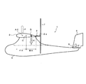
- FIG. 3 shows a side view of the vertical take-off and landing aircraft 1.
- the center of gravity G of the aircraft where the weight of the aircraft acts as indicated by an arrow X is set to an area BA (hereinafter referred to as a trailing edge area) on the trailing edge side of the chord center C of the main wing 3.
- the center of gravity G of the fuselage is set in an area FA (hereinafter referred to as a front edge side area) on the leading edge side of the chord center C of the main wing 3, but in the vertical take-off and landing aircraft 1 according to the present invention, it is located in the trailing edge area BA. Is set.
- the installation position of the drive source 8 is retracted from the normal position in the vicinity of the main wing 3 as shown in FIG. 1.
- the center of gravity G of the fuselage is set behind the aerodynamic center AC (Aerodynamic Center) where the lift of the main wing 3 acts as shown by the arrow Y.
- the horizontal tail 5 has a wing shape and an installation angle that generate lift upward as indicated by an arrow Z during horizontal flight, contrary to normal, and the upward lift (arrow Y) acting on the aerodynamic center AC. )
- the downward body weight acting on the center of gravity G (arrow X), and the upward lift (arrow Z) generated in the horizontal tail 5 the balance (balance in the pitching direction) can be maintained.
- the area of the horizontal tail 5 is set wider than that of a normal aircraft in which the center of gravity G of the aircraft is set in the front edge side area FA of the main wing 3 in order to improve stability.
- Rotors 7 (hereinafter also referred to as rotor blades) are respectively attached to the tips of the left and right rotor shafts 2. The rotor blade 7 can change the cyclic pitch and the collective pitch in the same manner as a normal helicopter.
- FIG. 4 shows a rear view of the vertical take-off and landing aircraft 1 in which the left and right rotor shafts 2 are in a vertical posture.
- the horizontal tail 5 and the vertical tail 6 are omitted.
- An upper angle ⁇ (for example, about 3 degrees) is set for the main wing 3, and the left and right rotor shafts 2 are respectively attached to the left and right main wings 3 so as to be orthogonal to each other.
- the direction (arrow W) of the wind (thrust) generated by the left and right rotors 7 is slightly directed outward in the width (span) direction of the main wing 3, and the resultant force of the left and right rotors 7 is the fuselage. Acting on the center line CL. Therefore, the stability of the airframe is improved during vertical ascent (descent) than when the rotor shaft 2 is perpendicular to the ground.
- FIG. 5 is a partial plan sectional view of the vertical take-off and landing aircraft 1 in which the left and right rotor shafts 2 are in a horizontal posture
- FIG. 6 (a) is a partially enlarged view of FIG. 5
- FIG. 6 (b) is FIG.
- F represents the front
- R represents the rear.
- the left and right rotor shafts 2 are rotated between a vertical posture and a horizontal posture by a rotating means 13.
- the rotation means 13 includes a rotation support mechanism 14 that supports the left and right rotor shafts 2 on the main wing 3 so as to be rotatable between a vertical posture and a horizontal posture around the center of gravity position G, and the left and right rotor blades 7.
- a pitch changing mechanism 15 for changing the click pitch and a lock mechanism 16 for fixing the rotation angle of the left and right rotor shafts 2 are provided.
- the rotation support mechanism 14 includes a pipe 17 that is rotatably accommodated in the left and right main wings 3, and a shaft shaft support 18 that is attached to the tip of the pipe 17.
- the rotor shaft 2 is rotatably supported on the shaft support portion 18.
- the pipe 17 extends from the base portion of the main wing 3 (attachment portion to the fuselage 4) to the notch 19 of the main wing 3 toward the wing tip of the main wing 3, and includes bearings 20 provided on the main wing 3 and the fuselage 4. 21 is rotatably supported around the axis.
- the notch 19 is formed in the middle of the main wing 3 in the span direction so as to cut out the rear edge side of the main wing 3.
- a shaft shaft support 18 attached to the tip of the pipe 17 is formed inside the notch 19. It is arranged so that it can rotate. With this configuration, as the pipe 17 rotates, the shaft shaft support 18 rotates inside the notch 19 and the rotor shaft 2 supported by the shaft shaft support 18 moves between the vertical posture and the horizontal posture. To rotate. The rotation angles of the left and right rotor shafts 2 are synchronized by the interlocking mechanism 22.
- Interlocking mechanism 22 As shown in FIGS. 5, 6 (a), and 6 (b), the rotation angles of the left and right pipes 17 accommodated in the left and right main wings 3 are synchronized by the interlock mechanism 22. It is supposed to be an angle.
- the interlocking mechanism 22 is disposed along the span direction inside the base portion of the main wing 3 on the first bracket 23 attached to the end portion of the main wing 3 of the left and right pipes 17 and supported by the bearing 24.
- the interlocking shaft 25, the second bracket 26 attached to the left and right of the interlocking shaft 25 in the span direction, and the connecting arm 27 that connects the second bracket 26 and the first bracket 23 are provided.
- the first bracket 23, the connecting arm 27, and the second bracket 26 constitute a link mechanism.
- the fluctuation of the rotation angle of one of the left and right pipes 17 causes the first bracket 23, the connecting arm 27, the second bracket 26, the interlocking shaft 25, the other second bracket 26, and the connection. Since it is transmitted to the other pipe 17 via the arm 27 and the first bracket 23, the rotation angles of the left and right pipes 17 are synchronized. As a result, the rotation angles of the left and right rotor shafts 2 are synchronized.
- the left and right rotor shafts 2 are provided with a pitch changing mechanism 15 that changes the cyclic pitch of the rotor (rotor blade) 7.
- the pitch changing mechanism 15 has the same configuration as a normal helicopter (including a radio control), and changes the cyclic pitch and collective pitch of the rotor blade 7.
- the pitch changing mechanism 15 includes a swash plate 28 inserted through the rotor shaft 2. The swash plate 28 is inclined with respect to the rotor shaft 2 to change the cyclic pitch of the rotor blade 7, and the swash plate 28 is moved to the rotor. The collective pitch of the rotor blade 7 is changed by moving along the shaft 2 or the like.
- the swash plate 28 is inclined and moved through a link 30 by a rotor controller 29 attached to the shaft support portion 18.
- the rotor controller 29 and the link 30 are separated from the rotation of the rotor shaft 2.
- the link 30 is operated by a servo motor or the like provided in the rotor controller 29.
- the cyclic pitch of the rotor blade 7 is set so that the rotation angle of the rotor shaft 2 supported by the rotation support mechanism 14 so as to be rotatable about the center of gravity G on the main wing 3 is perpendicular to the horizontal posture. It has a function to control so as to change between postures. Specifically, when the rotor shaft 2 is in the vertical posture as shown in FIG. 7A, the pitch changing mechanism 15 is more than the lift force F1 on the front half side 7f of the rotor 7 as shown in FIG. 7B. It has a function of changing the cyclic pitch of the rotor 7 so as to increase the lift force F2 of the rear half side 7r.
- the pitch changing mechanism 15 makes the cyclic pitch of the rotor 7 constant and eliminates the unbalance of the lift of the rotor 7 as shown in FIG.
- Such cyclic pitch control is applied when the rotor shaft 2 is changed from the vertical posture to the horizontal posture, that is, when the state is changed from the state where the aircraft is vertically raised and lowered to the forward state.
- the pitch changing mechanism 15 is cyclic with the rotor 7 in a state where the rotor shaft 2 is held in a horizontal posture.
- the pitch is fixed and the collective pitch is controlled. Increasing the collective pitch increases the speed of the aircraft during forward flight, and decreasing the collective pitch decreases the speed.
- the pitch changing mechanism 15 is located on the lower half side 7d of the lift F3 on the upper half side 7u of the rotor 7 as shown in FIG. 8B. It has a function of changing the cyclic pitch of the rotor 7 so as to increase the lift F4. As the lift of the rotor 7 becomes unbalanced in this way, as shown in FIG. 8C, the rotation surface of the rotor 7 tilts backward and the rotor shaft 2 rotates downward, and FIG. As shown in d), the rotor shaft 2 is in a vertical posture.
- the pitch changing mechanism 15 makes the cyclic pitch of the rotor 7 constant and eliminates the unbalance of the lift force of the rotor 7 as shown in FIG.
- Such cyclic pitch control is applied when the rotor shaft 2 is changed from a horizontal posture to a vertical posture, that is, when the state in which the aircraft is moving forward is switched to a vertical ascending / descending state.
- the pitch changing mechanism 15 sets the cyclic pitch of the rotor 7 while the rotor shaft 2 is held in the vertical posture.
- the collective pitch is controlled with a constant value. Increasing the collective pitch raises the aircraft vertically, and decreasing the collective pitch lowers the aircraft.
- the lock mechanism 16 As shown in FIGS. 5 and 6A, the left and right pipes 17 accommodated in the left and right main wings 3 are respectively locked in the middle of the interlocking shaft 25 by locking (fixing) the rotation of the interlocking shaft 25.
- a lock mechanism 16 is provided for fixing the rotation angle of the left and right rotor shafts 2.
- the lock mechanism 16 has a so-called drum brake structure in which a shoe is pressed against the inner peripheral surface of a drum fixed to the interlocking shaft 25, or a disk brake structure in which a disk fixed to the interlocking shaft 25 is clamped by a pad.
- the rotation angle of the rotor shaft 2 fixed by the lock mechanism 16 is limited to the vertical posture angle (90 degrees) shown in FIG. 7A and the horizontal posture angle (0 degrees) shown in FIG. Absent.
- the lock mechanism 16 rotates the interlock shaft 25 while the rotor shaft 2 is rotating from FIG. 7A to FIG. 7E or from FIG. 8A to FIG. 8E.
- the left and right rotor shafts 2 can be tuned and fixed at an arbitrary angle in the range of 0 to 90 degrees.
- the power transmission mechanism 9 transmits the rotational force of the drive source 8 accommodated in the fuselage 4 to the gear box 10 accommodated inside the base portion of the main wing 3 via the first drive shaft 11. Then, it is transmitted from the gear box 10 to the left and right rotor shafts 2 via the left and right second drive shafts 12, and the left and right rotor shafts 2 are reversely rotated.
- the gear box 10 rotates the left and right second drive shafts 12 in the same direction.
- the left and right second drive shafts 12 extend from the gear box 10 outward in the span direction of the left and right main wings 3, and are inserted through holes 31 formed in the first bracket 23 of the interlock mechanism 22.
- the inside of the pipe 17 of the dynamic support mechanism 14 is inserted and extended to the shaft support portion 18 attached to the tip of the pipe 17.
- the second drive shaft 12 is rotatably supported on the inner peripheral surface of the pipe 17 via a bearing 32, and varies independently of the rotation of the pipe 17, that is, depending on the rotation angle of the pipe 17.
- the rotor 8 is rotated by the drive source 8 and the gear box 10 regardless of the rotation angle of the rotor shaft 2.
- bevel gears 33 are attached to the tips of the left and right second drive shafts 12, respectively.
- the bevel gear 33 is meshed with a bevel gear 34 attached to the end of the rotor shaft 2 that is rotatably supported by the shaft shaft support portion 18.
- the rotational force of the drive source 8 shown in FIG. 1 is transmitted to the gear box 10 shown in FIG. 5 via the first drive shaft 11, and the left and right second drive shafts 12 are in the same direction.
- the left and right rotor shafts 2 are rotated in opposite directions through the bevel gears 33 and 34.
- left and right second drive shafts 12 are rotated independently of the rotation of the left and right pipes 17, the left and right rotor shafts 2 are different from the left and right rotor shafts 2 that vary depending on the rotation state of the left and right pipes 17. Regardless of the rotation angle, they are driven to rotate at the same rotation speed (rpm) in synchronization with each other in opposite directions.
- the intersection of the extension line of the rotor shaft 2 and the extension line of the second drive shaft 12 is the center of gravity position G of the airframe, and the rotor shaft 2 is virtually shown in FIG. As indicated by the line, it pivots downward about the center of gravity G of the aircraft.
- the center of gravity position G shown in FIG. 5 is located on a line extending to the side of the aircraft through the center of gravity in the front-rear direction that exists only in the aircraft shown in FIG. 3, and the line and the rotor shaft 2 are connected to each other. This is the position where the extended line intersects.
- the length L1 from the center of gravity position G to the rotor mounting portion at the tip of the rotor shaft 2 is set according to the length L2 from the center of gravity position G to the rear edge of the main wing 3, and the rotor 7 is connected to the main wing 3. It does not interfere with the trailing edge.
- the locking shaft 16 is released from being fixed by rotating the rotor 7 as shown in FIG. After the surface is inclined in the forward direction, as shown in FIG. 7 (d), the rotating surface of the rotor 7 is directed rearward of the main wing 3, and the rotor shaft 2 is set in a horizontal posture. If the rotor shaft 2 is in a horizontal posture, the rotation of the interlocking shaft 25 is fixed by the lock mechanism 16 to fix the rotation surfaces of the left and right rotors 7 backward, and the forward flight is started. At the time of forward flight, as shown in FIG.
- the pitch change mechanism 15 makes the cyclic pitch of the rotor 7 constant, thereby eliminating the lift imbalance of the rotor 7 and controlling the collective pitch. You can change the speed.
- the rotation surface of the rotor 7 is fixed in the state inclined in the advancing direction by fixing the interlocking shaft 25 with the locking mechanism 16 in the state where the rotor shaft 2 was inclined.
- the pitch changing mechanism 15 makes the collective pitch constant so as to balance the weight of the aircraft. Can be hovered, and the aircraft can be freely moved back and forth and left and right by controlling the cyclic pitch in this state. Further, by controlling the inclination angle of the rotor shaft 2 shown in FIG. 7C, it is possible to cruise stably from low speed to high speed.
- the vertical take-off and landing aircraft 1 sets the center of gravity G of the aircraft in the area BA on the trailing edge side of the chord center C of the main wing 3 when the aircraft is viewed from the side.
- the rotor shaft 2 extends downward from the center of gravity position G, and the rotor shaft 2 is rotated between a vertical posture in which the tip 2 a faces downward of the main wing 3 and a horizontal posture in which the tip 2 a faces rearward of the main wing 3. Since the rotor shaft 2 in the vertical posture is disposed at the center of gravity position G of the fuselage, the lift action position (rotor shaft 2 position) by the rotor 5 matches the fuselage weight action position (center of gravity position G). No pitching moment is generated, and the aircraft is stably raised or lowered vertically.
- the rotor shaft 2 extends downward from the center of gravity position G of the airframe set in the rear edge area BA of the main wing 3, the rotor shaft 2 is rotated rearward about the center of gravity position G to obtain a horizontal posture.
- the center of gravity position G of the fuselage is the front edge side area FA of the main wing 3 (from the leading edge to the chord). The position can be shorter than the normal case where it is set at a position about 25% to 30% of the rear position.
- the rotor shaft 2 can be made shorter than usual, when the rotor shaft 2 is vertically oriented with the tip 2a facing downward, and the rotor 7 is directed below the main wing 3, the distance between the rotating surface of the rotor 7 and the ground is secured. It is possible to lower the position of the main wing 3 as compared with the normal case so that the rotating surface of the rotor 7 comes close to the ground, and the height of the center of gravity of the fuselage can be lowered. Therefore, the stability during vertical ascent (descent) is improved.
- the rotor shaft 2 is rotated by supporting the rotor shaft 2 on the main wing 3 so as to be rotatable between a vertical posture and a horizontal posture around the center of gravity G, and changing the cyclic pitch of the rotor 7.
- the rotor shaft 2 can be rotated without difficulty as compared with the case where the rotor shaft 2 itself is directly rotated by the actuator while the rotor 7 is rotating, and the stress applied to the rotor shaft 2 is small, which is reliable and durable. Will improve.
- Rotation angles of the left and right rotor shafts 2 are synchronized by the interlocking mechanism 22. Therefore, it is possible to avoid instability of the airframe due to uneven rotation angles of the left and right rotor shafts 2.
- the rotational speeds (rpm) of the left and right rotors 7 are tuned by the power transmission mechanism 9. Therefore, it is possible to avoid instability of the airframe due to uneven rotation speeds of the left and right rotors 7.
- the aerodynamic center (lift center) AC of the main wing 3 is in front of the center of gravity position G. That is, normally, the center of gravity G is set in front of the aerodynamic center AC, but in this airframe, it is reversed.
- the horizontal tail 5 has a wing shape and mounting angle that generate lift Z during horizontal flight, contrary to normal.
- the lift Y of the main wing 3 acting on the aerodynamic center AC, the fuselage weight X acting on the center of gravity G, and the lift Z generated on the horizontal tail 5 cause The balance in the pitching direction can be maintained. Moreover, stability is improved by setting the area of the horizontal tail 5 wider than usual.
- FIG. 9 shows a vertical take-off and landing aircraft 1a according to a modification of the present invention.
- This vertical take-off and landing aircraft 1a is different from the previous embodiment in that the aerodynamic center AC is a main wing 3a located behind the center of gravity G of the fuselage, and the other configuration is substantially the same as the previous embodiment. Therefore, the same components as those in the previous embodiment are denoted by the same reference numerals, description thereof is omitted, and differences will be described.
- the main wing 3a of the vertical take-off and landing aircraft 1a has a chord center C rather than a camber between the leading edge and the chord center C so that the aerodynamic center AC of the main wing 3 is positioned on the rear edge side of the center of gravity position G of the fuselage.
- the camber between the wing and the trailing edge is a large wing shape. It should be noted that between the leading edge and the chord center C, the camber may be zero and a symmetrical wing may be used.
- the aerodynamic center AC can be set behind the center of gravity position G even if the center of gravity G of the airframe is set in the trailing edge area BA of the main wing 3a.
- the horizontal tail 5a can have the wing shape and mounting angle that generate the downward force Za during horizontal flight as in the normal case. This improves the stability of the aircraft.
- description thereof will be omitted.
- the vertical take-off and landing aircraft according to the present invention can be applied not only to transportation of people and cargo, but also to unmanned observation aircraft, radio control aircraft, and the like.
- the present invention can be used for a vertical take-off and landing aircraft that takes off and land vertically by turning the rotor rotating surface downward and moves forward by turning the rotor rotating surface backward.
Landscapes
- Engineering & Computer Science (AREA)
- Aviation & Aerospace Engineering (AREA)
- Toys (AREA)
Abstract
La présente invention concerne un aéronef à décollage et atterrissage verticaux qui décolle et atterrit verticalement avec le plan de rotation d'un rotor faisant face au côté inférieur d'une aile principale, et qui se déplace vers l'avant avec le plan de rotation du rotor faisant face au côté arrière de l'aile principale, l'aéronef à décollage et atterrissage verticaux permettant de réduire la longueur d'un arbre de rotor grâce à une structure légère et simple. Dans l'aéronef à décollage et atterrissage verticaux selon l'invention, la position du centre de gravité (G) du corps de l'aéronef est définie dans une zone (BA) du côté du bord de fuite depuis le centre de corde (C) de l'aile principale (3), un arbre de rotor (2) s'étend vers le bas depuis la position du centre de gravité (G) et l'arbre de rotor (2) est entraîné en rotation entre une attitude verticale, dans laquelle son extrémité d'attaque (2a) fait face au côté inférieur de l'aile principale (3), et une attitude horizontale, dans laquelle son extrémité d'attaque (2a) fait face au côté du bord de fuite de l'aile principale (3). Puisque l'arbre de rotor (2) s'étend vers le bas depuis la position du centre de gravité (G) définie dans la zone (BA) du côté du bord de fuite de l'aile principale (3), lorsque l'arbre de rotor (2) est amené dans l'attitude horizontale en étant entraîné en rotation vers le bas, la longueur de l'arbre de rotor (2) requise pour placer le plan de rotation d'un rotor (7) sur le côté arrière depuis le bord de fuite de l'aile principale (3) peut être réduite.
Applications Claiming Priority (4)
| Application Number | Priority Date | Filing Date | Title |
|---|---|---|---|
| JP2011177280 | 2011-07-27 | ||
| JP2011-177280 | 2011-07-27 | ||
| JP2012-085436 | 2012-04-04 | ||
| JP2012085436A JP5150001B1 (ja) | 2011-07-27 | 2012-04-04 | 垂直離着陸機 |
Publications (1)
| Publication Number | Publication Date |
|---|---|
| WO2013015295A1 true WO2013015295A1 (fr) | 2013-01-31 |
Family
ID=47601136
Family Applications (1)
| Application Number | Title | Priority Date | Filing Date |
|---|---|---|---|
| PCT/JP2012/068768 Ceased WO2013015295A1 (fr) | 2011-07-27 | 2012-07-25 | Aéronef à décollage et atterrissage verticaux |
Country Status (2)
| Country | Link |
|---|---|
| JP (1) | JP5150001B1 (fr) |
| WO (1) | WO2013015295A1 (fr) |
Cited By (4)
| Publication number | Priority date | Publication date | Assignee | Title |
|---|---|---|---|---|
| EP3299279A1 (fr) * | 2016-09-21 | 2018-03-28 | Bell Helicopter Textron Inc. | Aeronef avec un moteur monté dans le fuselage et une aile escamotable |
| US10343762B2 (en) | 2016-09-21 | 2019-07-09 | Bell Helicopter Textron, Inc. | Fuselage mounted engine with wing stow |
| US10414483B2 (en) | 2016-09-21 | 2019-09-17 | Bell Helicopter Textron, Inc. | Tiltrotor articulated wing extension |
| WO2024224035A1 (fr) * | 2023-04-26 | 2024-10-31 | Leonardo UK Ltd | Aéronef |
Citations (6)
| Publication number | Priority date | Publication date | Assignee | Title |
|---|---|---|---|---|
| US2478847A (en) * | 1944-10-06 | 1949-08-09 | Gen Motors Corp | Convertible helicopter-airplane |
| CH380540A (de) * | 1960-11-18 | 1964-07-31 | Aero Consultor Ag | Propellergetriebenes Verwandlungsflugzeug mit Starrflügel |
| JPH092395A (ja) * | 1995-06-15 | 1997-01-07 | Kazuhiro Takahashi | 垂直離着陸機 |
| US5839691A (en) * | 1996-05-22 | 1998-11-24 | Lariviere; Jean Soulez | Vertical takeoff and landing aircraft |
| US6382556B1 (en) * | 1999-12-20 | 2002-05-07 | Roger N. C. Pham | VTOL airplane with only one tiltable prop-rotor |
| US7753309B2 (en) * | 2007-03-22 | 2010-07-13 | Oliver Garreau | VTOL/STOL tilt-prop flying wing |
-
2012
- 2012-04-04 JP JP2012085436A patent/JP5150001B1/ja not_active Expired - Fee Related
- 2012-07-25 WO PCT/JP2012/068768 patent/WO2013015295A1/fr not_active Ceased
Patent Citations (6)
| Publication number | Priority date | Publication date | Assignee | Title |
|---|---|---|---|---|
| US2478847A (en) * | 1944-10-06 | 1949-08-09 | Gen Motors Corp | Convertible helicopter-airplane |
| CH380540A (de) * | 1960-11-18 | 1964-07-31 | Aero Consultor Ag | Propellergetriebenes Verwandlungsflugzeug mit Starrflügel |
| JPH092395A (ja) * | 1995-06-15 | 1997-01-07 | Kazuhiro Takahashi | 垂直離着陸機 |
| US5839691A (en) * | 1996-05-22 | 1998-11-24 | Lariviere; Jean Soulez | Vertical takeoff and landing aircraft |
| US6382556B1 (en) * | 1999-12-20 | 2002-05-07 | Roger N. C. Pham | VTOL airplane with only one tiltable prop-rotor |
| US7753309B2 (en) * | 2007-03-22 | 2010-07-13 | Oliver Garreau | VTOL/STOL tilt-prop flying wing |
Cited By (4)
| Publication number | Priority date | Publication date | Assignee | Title |
|---|---|---|---|---|
| EP3299279A1 (fr) * | 2016-09-21 | 2018-03-28 | Bell Helicopter Textron Inc. | Aeronef avec un moteur monté dans le fuselage et une aile escamotable |
| US10343762B2 (en) | 2016-09-21 | 2019-07-09 | Bell Helicopter Textron, Inc. | Fuselage mounted engine with wing stow |
| US10414483B2 (en) | 2016-09-21 | 2019-09-17 | Bell Helicopter Textron, Inc. | Tiltrotor articulated wing extension |
| WO2024224035A1 (fr) * | 2023-04-26 | 2024-10-31 | Leonardo UK Ltd | Aéronef |
Also Published As
| Publication number | Publication date |
|---|---|
| JP2013047090A (ja) | 2013-03-07 |
| JP5150001B1 (ja) | 2013-02-20 |
Similar Documents
| Publication | Publication Date | Title |
|---|---|---|
| JP5277342B1 (ja) | 垂直離着陸機 | |
| JP7670383B2 (ja) | 航空機アセンブリ、航空機の翼アセンブリ及び航空機を製造する方法 | |
| US10173771B2 (en) | Tiltrotor aircraft having rotatable wing extensions | |
| CN1078557C (zh) | 垂直起落飞机 | |
| US8690096B2 (en) | Aircraft with dual flight regimes | |
| US7137591B2 (en) | Tilting mast in a rotorcraft | |
| KR101731010B1 (ko) | 양력과 병진운동 추진력을 제공하는 회전날개 항공기용 안티토크 테일 로터 | |
| US6343768B1 (en) | Vertical/short take-off and landing aircraft | |
| EP2148814B1 (fr) | Hélicoptère hybride rapide à grande distance franchissable et avec contrôle de l'assiette longitudinale | |
| EP1212238B1 (fr) | Perfectionnements aux aeronefs convertibles a rotors basculants | |
| US8939394B1 (en) | Anemometer drive apparatus and method | |
| US20020011539A1 (en) | Hovering gyro aircraft | |
| US9611036B1 (en) | Rotor-mast-tilting apparatus and method for lower flapping loads | |
| FR2916418A1 (fr) | Helicoptere hybride rapide a grande distance franchissable. | |
| JPH03176297A (ja) | 飛行機 | |
| CA2489591A1 (fr) | Commande d'un aeronef en tant que pendule oriente par la poussee en mode vertical, en mode horizontal et dans tous les modes de vol de transition entre ces derniers | |
| KR20220029575A (ko) | 강성 날개 공기역학을 시뮬레이션하기 위해 고정된 전방으로 기울어진 회전자를 사용하는 수직 이착륙 항공기 | |
| CN109515704B (zh) | 基于摆线桨技术的涵道卷流旋翼飞行器 | |
| JP2009051381A (ja) | サイクロイダル・ブレード | |
| JP5150001B1 (ja) | 垂直離着陸機 | |
| JP2018086916A (ja) | 飛行体 | |
| CN105923156A (zh) | 直升机v型旋翼装置 | |
| KR100810725B1 (ko) | 수직 이착륙 비행체 | |
| CN217198642U (zh) | 螺旋桨组件及无人机 | |
| JP2022059231A (ja) | 航空機の回転翼制御機構 |
Legal Events
| Date | Code | Title | Description |
|---|---|---|---|
| 121 | Ep: the epo has been informed by wipo that ep was designated in this application |
Ref document number: 12818103 Country of ref document: EP Kind code of ref document: A1 |
|
| NENP | Non-entry into the national phase |
Ref country code: DE |
|
| 122 | Ep: pct application non-entry in european phase |
Ref document number: 12818103 Country of ref document: EP Kind code of ref document: A1 |