WO2013015324A1 - Dispositif électronique - Google Patents
Dispositif électronique Download PDFInfo
- Publication number
- WO2013015324A1 WO2013015324A1 PCT/JP2012/068856 JP2012068856W WO2013015324A1 WO 2013015324 A1 WO2013015324 A1 WO 2013015324A1 JP 2012068856 W JP2012068856 W JP 2012068856W WO 2013015324 A1 WO2013015324 A1 WO 2013015324A1
- Authority
- WO
- WIPO (PCT)
- Prior art keywords
- housing
- electronic device
- vibration
- housing portion
- movable
- Prior art date
- Legal status (The legal status is an assumption and is not a legal conclusion. Google has not performed a legal analysis and makes no representation as to the accuracy of the status listed.)
- Ceased
Links
Images







Classifications
-
- B—PERFORMING OPERATIONS; TRANSPORTING
- B06—GENERATING OR TRANSMITTING MECHANICAL VIBRATIONS IN GENERAL
- B06B—METHODS OR APPARATUS FOR GENERATING OR TRANSMITTING MECHANICAL VIBRATIONS OF INFRASONIC, SONIC, OR ULTRASONIC FREQUENCY, e.g. FOR PERFORMING MECHANICAL WORK IN GENERAL
- B06B1/00—Methods or apparatus for generating mechanical vibrations of infrasonic, sonic, or ultrasonic frequency
- B06B1/02—Methods or apparatus for generating mechanical vibrations of infrasonic, sonic, or ultrasonic frequency making use of electrical energy
- B06B1/04—Methods or apparatus for generating mechanical vibrations of infrasonic, sonic, or ultrasonic frequency making use of electrical energy operating with electromagnetism
- B06B1/045—Methods or apparatus for generating mechanical vibrations of infrasonic, sonic, or ultrasonic frequency making use of electrical energy operating with electromagnetism using vibrating magnet, armature or coil system
Definitions
- the present invention relates to an electronic device.
- This application claims priority based on Japanese Patent Application No. 2011-164310 for which it applied on July 27, 2011, and uses the content here.
- Patent Document 1 As an electronic device such as a mobile phone or a portable information terminal, for example, a technique described in Patent Document 1 is known.
- a configuration that allows a user to detect vibration may be used.
- a vibration generator for generating such vibration for example, a vibration motor is known.
- a vibration motor for example, a configuration in which a weight is attached to the tip of a cylindrical rotor and vibration is generated by the rotation of the rotor is known.
- the conventional vibration generator is configured to transmit vibration to the housing via the motor, there may be a case where vibration is not sufficiently transmitted to the outside.
- An object of an aspect of the present invention is to provide an electronic device that can efficiently transmit vibration to the outside.
- a housing having an electronic circuit and having a first housing portion and a second housing portion, and vibrating in a predetermined direction, the first housing portion and the second housing portion.
- An electronic device in which at least a part of at least one of the first housing part and the second housing part is exposed to the outside.
- FIG. 11 is a diagram illustrating a partial configuration of an electronic apparatus according to the embodiment.
- FIG. 11 is a diagram illustrating a partial configuration of an electronic apparatus according to the embodiment.
- FIG. 11 is a diagram illustrating a partial configuration of an electronic apparatus according to the embodiment.
- FIG. 14 is a diagram showing an operation state of the electronic apparatus according to the embodiment.
- the disassembled perspective view which shows the structure of the electronic device which concerns on 2nd embodiment of this invention.
- FIG. 11 is a diagram illustrating a partial configuration of an electronic apparatus according to the embodiment.
- FIG. 11 is a diagram illustrating a partial configuration of an electronic apparatus according to the embodiment.
- FIG. 11 is a diagram illustrating a partial configuration of an electronic apparatus according to the embodiment.
- FIG. 11 is a diagram illustrating a partial configuration of an electronic apparatus according to the embodiment.
- FIG. 11 is a diagram illustrating a partial configuration of an electronic apparatus according to the embodiment.
- FIG. 14 is a diagram showing an operation state of the electronic apparatus according to the embodiment.
- the disassembled perspective view which shows the structure of the electronic device which concerns on 3rd embodiment of this invention.
- FIG. 11 is a diagram illustrating a partial configuration of an electronic apparatus according to the embodiment.
- FIG. 11 is a diagram illustrating a partial configuration of an electronic apparatus according to the embodiment.
- FIG. 11 is a diagram illustrating a partial configuration of an electronic apparatus according to the embodiment.
- FIG. 11 is a diagram illustrating a partial configuration of an electronic apparatus according to the embodiment.
- FIG. 11 is a diagram illustrating a partial configuration of an electronic apparatus according to the embodiment.
- FIG. 11 is a diagram illustrating a partial configuration of an electronic apparatus according to the embodiment.
- FIG. 16 is a diagram showing an operation state of the electronic apparatus according to the embodiment.
- FIG. 16 is a diagram illustrating a partial structure of an electronic device according to another embodiment of the invention.
- FIG. 16 is a diagram illustrating a partial structure of an electronic device according to another embodiment of the invention.
- FIG. 16 is a diagram illustrating a partial structure of an electronic device according to another embodiment of the invention.
- FIG. 1 is an exploded perspective view showing a configuration of an electronic device 100 according to the first embodiment of the present invention.
- the electronic device 100 includes a display panel 10, a first base portion 11, a second base portion 12, a battery 13, a first substrate 14, a bottom cover 15, a vibration portion 16, a suspension 19, and an operation portion 22.
- the second substrate 25 and the cover member 26 are provided.
- the electronic device 100 is assembled in a state where these components are stacked.
- an XYZ orthogonal coordinate system is used to describe the configuration of the electronic device 100.
- the stacking direction of each component of the electronic device 100 is defined as the Z direction.
- a plane orthogonal to the Z direction is defined as an XY plane, and directions orthogonal to the XY plane are defined as an X direction and a Y direction, respectively.
- the display panel 10 is formed in a rectangle when viewed in the Z direction.
- the display panel 10 has a display surface 10a on the ⁇ Z side surface. Images such as still images and moving images are displayed on the display surface 10a.
- a liquid crystal display panel or an organic EL panel is used as the display panel 10.
- a touch panel mechanism (not shown) can be provided on the display surface 10 a of the display panel 10.
- the first base unit 11 holds the display panel 10.
- the first base portion 11 is formed in a rectangular frame shape when viewed in the Z direction.
- the 1st base part 11 is formed so that the side part of the display panel 10 and the peripheral part of the display surface 10a may be enclosed.
- the second base portion 12 is disposed on the + Z side of the first base portion 11. A part of the second base portion 12 is supported by the first base portion 11.
- the 1st base part 11 and the 2nd base part 12 are the 1st housing
- the battery 13 is formed in a rectangular plate shape.
- the battery 13 supplies power to each part of the electronic device 100.
- the battery 13 is connected to each part of the electronic device 100 via a wiring (not shown).
- the surface 13a on the + Z side of the battery 13 is formed flat.
- the outer shape of the first substrate 14 is formed in an L shape so as to open a space in which the battery 13 is disposed.
- the first substrate 14 is supported by the second base portion 12.
- a control circuit 14 a is formed on the first substrate 14.
- the electronic device 100 is configured such that each part of the electronic device 100 is electrically controlled by the control circuit 14a.
- the bottom cover 15 is formed in a rectangular plate shape.
- the bottom cover 15 is disposed on the + Z side of the battery 13 and the first substrate 14 and is disposed so as to cover the battery 13 and the first substrate 14.
- a circular opening 15 a is formed at the center of the bottom cover 15. A part of the surface 13a on the + Z side of the battery 13 is exposed in the opening 15a.
- the vibration part 16 has a fixed part 16a, a movable part 16b, and a drive part 16c.
- the fixed portion 16a is formed in a cylindrical shape and houses the movable portion 16b and the drive portion 16c.
- the fixed portion 16 a is disposed in the opening 15 a of the bottom cover 15.
- the movable part 16b is provided so as to be movable in the Z direction.
- the drive unit 16c is connected to the movable unit 16b and moves the movable unit 16b in the Z direction.
- As the drive unit 16c for example, a voice coil motor or the like is used.
- the driving operation of the driving unit 16 c is controlled by the control circuit 14 a provided on the first substrate 14.
- the vibration part 16 has a configuration in which the movable part 16b vibrates in the Z direction when the drive part 16c reciprocates the movable part 16b in the Z direction.
- the suspension 19 is a part that supports the cover member 26.
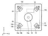
- FIG. 2 is a plan view showing a configuration on the bottom cover 15. As shown in FIG. 2, one suspension 19 is disposed at each of the four corners of the bottom cover 15. Each suspension 19 has a fixed portion 19a and a placement portion 19b. The fixing portion 19a is fixed to the bottom cover 15 by a fixing member such as a screw. A part of the second substrate 25 is placed on the placement portion 19b.
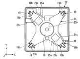
- FIG. 3 is a plan view showing a configuration on the second substrate 25.
- an electronic component having an electronic circuit such as a microprocessor 25 a is attached to the second substrate 25.
- the second substrate 25 is connected to the first substrate 14.
- An opening 25 b is formed at the center of the second substrate 25.
- a fixed portion 16a of the vibrating portion 16 is disposed in the opening 25b.
- FIG. 4 is a diagram illustrating a cross-sectional configuration of the electronic device 100.
- some components are omitted in order to make it easy to identify the components of the electronic device 100.
- the cover member 26 covers the + Z side end of the electronic device 100.
- a part 26a of the cover member 26 is detachably provided.
- the cover member 26 has a holding portion 26 b that holds the operation portion 22.
- the cover member 26 is a second housing portion 102 for accommodating an electronic circuit.
- the housing 103 of the electronic device 100 is configured by the second housing portion 102 and the first housing portion 101 including the first base portion 11 and the second base portion 12 described above.
- at least a part of the first housing portion 101 is exposed to the outside.
- at least a part of the second housing portion 102 is exposed to the outside.
- the first housing part 101 and the second housing part 102 are connected via the vibration part 16.
- the cover member 26 is connected to the movable portion 16 b of the vibrating portion 16. Therefore, the cover member 26 is provided so as to be movable in the Z direction integrally with the movable portion 16b.
- the vibration of the movable portion 16b is transmitted to the cover member 26, and the cover member 26 vibrates in the Z direction.
- the cover member 26 moves in the + Z direction as the movable portion 16b moves as shown in FIG. Accordingly, the space between the first housing portion 101 and the second housing portion 102 is widened, and the relative movement between the first housing portion 101 and the second housing portion 102 has been performed. become.
- the cover member 26 moves in the ⁇ Z direction with the movement of the movable portion 16b, and returns to the state shown in FIG. Also in this case, a relative movement has been performed between the first housing portion 101 and the second housing portion 102. In the case of this embodiment, the cover member 26 vibrates by reciprocating (vibrating) the movable portion 16b in the Z direction.
- the housing 103 having the first housing portion 101 and the second housing portion 102 for housing the electronic circuit, and the first housing portion that vibrates in a predetermined direction. Since the vibration unit 16 that relatively moves the 101 and the second housing portion 102 is provided, at least one of the first housing portion 101 and the second housing portion 102 can be directly vibrated. As a result, vibration can be efficiently transmitted to the outside.
- FIG. 6 is an exploded perspective view showing the configuration of the electronic device 200 according to the second embodiment of the present invention.
- the electronic device 200 includes a display panel 210, a first base portion 211, a second base portion 212, a battery 213, a first substrate 214, a bottom cover 215, a vibration portion 216, a suspension 219, and a drive housing. 221, an operation unit 222, a second substrate 225, and a cover member 226.
- the electronic device 200 is assembled in a state where these components are stacked.
- the 1st base part 211 and the 2nd base part 212 serve as the 1st case part 201 for accommodating an electronic circuit. Further, an electronic circuit (not shown) is formed on the first substrate 214.
- an XYZ orthogonal coordinate system is used to describe the configuration of the electronic device 200.
- the stacking direction of each component of the electronic device 200 is defined as the Z direction.
- a plane orthogonal to the Z direction is defined as an XY plane, and directions orthogonal to the XY plane are defined as an X direction and a Y direction, respectively.
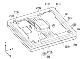
- FIG. 7 is a perspective view showing a configuration on the bottom cover 215.
- the bottom cover 215 is formed in a rectangular plate shape.
- the bottom cover 215 is disposed on the + Z side of the battery 213 and the first substrate 214, and is disposed so as to cover the battery 213 and the first substrate 214.
- a circular opening 215 a is formed at the center of the bottom cover 215. From the opening 215a, a part of the fixed part 216a of the vibration part 216 and the movable part 216b of the vibration part 216 protrude to the + Z side.
- One suspension 219 is disposed on each of the + X side and the ⁇ X side of the opening 215a.
- the driving unit 216c of the vibration unit 216 for example, a voice coil motor or the like can be used.
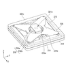
- FIG. 8 is a perspective view showing a configuration on the drive housing 221.
- the drive housing 221 has a connection part 221a, a connection part 221b, a frame part 221c, and an opening part 221d.
- the connection part 221a is a part connected to the movable part 216b.
- the connecting portion 221a is disposed at the central portion of the drive housing 221 as viewed in the Z direction, that is, at a position facing the movable portion 216b. By being connected to the movable portion 216b at the connection portion 221a, the drive housing 221 can move integrally with the movable portion 216b.
- the connecting part 221b connects the connecting part 221a and the frame part 221c.
- the connecting portion 221b is disposed on the + X side and the ⁇ X side of the connecting portion 221a, respectively.
- the connecting portion 221b is disposed at a position facing the suspension 219 when viewed in the Z direction.
- the connecting portion 221b is supported by the suspension 219.
- the frame portion 221c is supported on the peripheral edge portion of the second base portion 212.
- An opening 221d is formed in the frame portion 221c.
- the opening 221d is penetrated by a cylindrical protrusion 215b provided in the bottom cover 215.
- a smooth space is formed between the inner periphery of the opening 221d and the outer periphery of the protruding portion 215b. For this reason, friction between the inner periphery of the opening 221d and the outer periphery of the protrusion 215b is less likely to occur.
- the drive housing 221 is a second housing portion 202 for housing an electronic circuit.
- the housing 203 of the electronic device 200 is configured by the second housing portion 202 and the first housing portion 201 including the first base portion 211 and the second base portion 212 described above.
- FIG. 9 is a perspective view showing a configuration on the second substrate 225.
- the second substrate 225 is disposed on the + Z side of the drive housing 221.
- the second substrate 225 is disposed with a gap between it and the drive housing 221.
- An opening 225 a is formed at the center of the second substrate 225. In the opening 225a, a part of the fixed part 216a of the vibration part 216, a movable part 216b of the vibration part 216, and a part of the connection part 221a of the drive housing 221 are arranged.
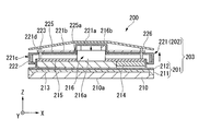
- FIG. 10 is a diagram illustrating a cross-sectional configuration of the electronic device 200.
- a part of the configuration is omitted for easy identification of the components of the electronic device 200.
- the cover member 226 covers the + Z side end of the electronic device 200.
- the cover member 226 is fixed to the bottom cover 215 together with the second substrate 225 via a fixing member 223 such as a screw.
- at least a part of the first housing portion 201 is exposed to the outside.
- at least a part of the second housing portion 202 is exposed to the outside.
- the first housing portion 201 and the second housing portion 202 are connected via the vibration unit 216.
- the drive housing 221 is connected to the movable part 216 b of the vibration part 216. Therefore, the drive housing 221 is provided so as to be movable in the Z direction integrally with the movable portion 216b.
- the vibration of the movable portion 216b is transmitted to the drive housing 221 and the drive housing 221 vibrates in the Z direction.
- the drive housing 221 moves in the + Z direction as the movable part 16b moves as shown in FIG. Therefore, the space between the first housing portion 201 and the second housing portion 202 is widened, and the relative movement between the first housing portion 201 and the second housing portion 202 has been performed. become.
- the drive housing 221 moves in the ⁇ Z direction as the movable part 216b moves, and returns to the state shown in FIG. Also in this case, a relative movement is performed between the first housing part 201 and the second housing part 202.
- the drive housing 221 vibrates in the Z direction by reciprocating (vibrating) the movable portion 216b in the Z direction.
- the housing 203 having the first housing portion 201 and the second housing portion 202 for housing the electronic circuit, and the first housing portion 201 that vibrates in a predetermined direction. Since the vibration unit 216 that relatively moves the second housing portion 202 is provided, at least one of the first housing portion 201 and the second housing portion 202 can be directly vibrated. As a result, vibration can be efficiently transmitted to the outside.
- FIG. 12 is an exploded perspective view showing the configuration of the electronic apparatus 300 according to this embodiment.
- the electronic device 300 includes a display panel 310, a base portion 311, a battery 313, a first substrate 314, a bottom cover 315, a vibration portion 316, a linear guide 317, a drive housing 321, and a fixed substrate 326. is doing.
- An electronic circuit (not shown) is formed on the first substrate 314.
- the base portion 311 is a first housing portion 301 for housing an electronic circuit.
- an XYZ orthogonal coordinate system is used to describe the configuration of the electronic device 300.
- the stacking direction of each component of the electronic device 300 is defined as the Z direction.
- a plane orthogonal to the Z direction is defined as an XY plane, and directions orthogonal to the XY plane are defined as an X direction and a Y direction, respectively.
- FIG. 13 is a perspective view showing a configuration on the bottom cover 315.
- a pair of linear guides 317 are attached on the bottom cover 315.
- the linear guide 317 is formed in a rectangular shape when viewed in the Z direction, and is arranged so that the longitudinal direction is parallel to the Y direction.
- the linear guide 317 guides the movement of the drive housing 321.
- FIG. 14 is a perspective view showing a configuration on the drive housing 321.
- the drive housing 321 is disposed on the + Z side of the bottom cover 315.
- the drive housing 321 is formed in a rectangle when viewed in the Z direction.
- the drive housing 321 includes a frame portion 321a and a beam portion 321b.
- the frame portion 321a is formed in a rectangular frame shape when viewed in the Z direction.
- the frame portion 321 a is supported on the peripheral edge portion of the base portion 311.
- the beam portion 321b is provided in a band shape within the frame of the frame portion 321a.
- the beam portion 321b is formed with a protrusion 321c and an opening 321d.
- a transmission member 316d that transmits the driving force of the vibration part 316 is joined to the beam part 321b.
- the transmission member 316d can move integrally with the beam portion 321b (drive housing 321).
- the movable part 316b of the vibration part 316 is connected to the transmission member 316d. The movement of the movable portion 316b is transmitted to the drive housing 321 via the transmission member 316d.
- the movable part 316b is arranged at a position in the Y direction with respect to the fixed part 316a. Therefore, the vibration part 316 vibrates in the Y direction along the surface of the bottom cover 315.
- a voice coil motor or the like can be used as the vibration part 316c of the vibration part 316.
- the protrusion 321c is formed in an L shape on the + Z side from the beam 321b.
- the protrusion 321 c is in contact with the linear guide 317.
- the protrusion 321c moves so as to slide in the Y direction along the linear guide 317, so that the drive housing 321 can move in parallel to the Y direction.
- the openings 321d are provided at the four corners of the drive housing 321, respectively.
- the drive housing 321 is a second housing portion 302 for housing an electronic circuit.
- the housing 303 of the electronic device 300 is configured by the second housing portion 302 and the first housing portion 301 including the base portion 311 described above.
- FIG. 15 is a perspective view showing a configuration on the fixed substrate 326.
- the fixed substrate 326 is disposed on the + Z side of the drive housing 321.
- the fixed substrate 326 is formed in a substantially rectangular shape when viewed in the Z direction.
- the fixed substrate 326 is fixed to the bottom cover 315 at four corners via fixing members (not shown).
- the fixing member passes through the opening 321d of the drive housing 321 and is fixed to the bottom cover 315.
- the outer diameter of the fixing member is smaller than the inner diameter of the opening 321d. Therefore, a gap (vibration margin) is formed between the fixing member and the beam portion 321b.
- the fixed substrate 326 has a stage 326a for fixing the fixing portion 316a of the vibrating portion 316.
- the movable portion 316b can move in the Y direction with respect to the stage 326a.
- FIG. 16 is a diagram illustrating a cross-sectional configuration of the electronic apparatus 300.
- a part of the configuration is omitted for easy identification of the components of the electronic device 300.
- at least a part of the first housing portion 301 (see FIG. 12) is exposed to the outside.
- at least a part of the second housing portion 302 (see FIG. 12) is exposed to the outside.
- the first housing portion 301 and the second housing portion 302 are connected via the vibration unit 316.
- the drive housing 321 is connected to the movable part 316b of the vibration part 316 via the transmission member 316d.
- the drive housing 321 can move in the Y direction integrally with the movable portion 316b.
- the vibration of the movable portion 316b is transmitted to the drive housing 321 and the drive housing 321 vibrates in the Z direction.
- the drive housing 321 can be vibrated so as to reciprocate on the same track by being guided by the linear guide 317.
- the drive housing 321 moves in the + Y direction as the movable part 316b moves as shown in FIG. Accordingly, the space between the first housing portion 301 and the second housing portion 302 is widened, and the relative movement between the first housing portion 301 and the second housing portion 302 has been performed. become.
- the drive housing 321 moves in the ⁇ Y direction as the movable portion 316b moves, and returns to the state shown in FIG. Also in this case, relative movement has been performed between the first housing portion 301 and the second housing portion 302. In the case of the present embodiment, the drive housing 321 vibrates in the Y direction by reciprocating (vibrating) the movable portion 316b in the Y direction.
- the housing 303 having the first housing portion 301 and the second housing portion 302 for housing the electronic circuit, and the first housing portion 301 that vibrates in a predetermined direction Since the vibration unit 316 that relatively moves the second housing portion 302 is provided, at least one of the first housing portion 301 and the second housing portion 302 can be directly vibrated. As a result, vibration can be efficiently transmitted to the outside.
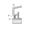
- FIG. 18 is a diagram illustrating an example of the configuration.
- a bellows portion 41 is provided between the second base portion 12 that is an example of the first housing portion and a cover member 26 that is an example of the second housing portion.
- the bellows portion 41 is provided over the entire outer periphery of the electronic device. Thereby, the inside of an electronic device can be protected from foreign materials, such as dust and dust.
- the configuration in which one vibration part is arranged has been described as an example.
- the present invention is not limited to this.
- a configuration in which a plurality of vibration units are arranged may be used.
- the vibration part can be provided at a plurality of positions.
- the configuration may be such that the vibration unit 16 is arranged at each of four corners of the electronic device 100.
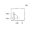
- the movable portion reciprocates is described as an example of the vibration by the vibration portion, but the present invention is not limited to this.
- the movable part 416b may reciprocate in a direction rotating around the fixed part 416a to generate vibration. I do not care.
- the electronic circuit is accommodated in the second casing portions 103, 203, and 303.
- all the electronic circuits are accommodated in the first casing portions 102, 201, and 301, and the second casing portion is accommodated.
- the body parts 103, 203, 303 may not contain electronic circuits.
Landscapes
- Physics & Mathematics (AREA)
- Electromagnetism (AREA)
- Engineering & Computer Science (AREA)
- Mechanical Engineering (AREA)
- Apparatuses For Generation Of Mechanical Vibrations (AREA)
- Telephone Set Structure (AREA)
Abstract
La présente invention concerne un dispositif électronique. Selon l'invention, un dispositif électronique comporte les éléments suivants : un boîtier qui renferme un circuit électronique et qui possède une première partie de boîtier et une seconde partie de boîtier ; et une partie de vibration qui vibre dans une direction prédéterminée et qui amène la première partie de boîtier et la seconde partie de boîtier à se déplacer l'une par rapport à l'autre. Au moins une partie d'au moins l'une de la première et de la seconde partie de boîtier est exposée à l'extérieur.
Applications Claiming Priority (2)
| Application Number | Priority Date | Filing Date | Title |
|---|---|---|---|
| JP2011164310 | 2011-07-27 | ||
| JP2011-164310 | 2011-07-27 |
Publications (1)
| Publication Number | Publication Date |
|---|---|
| WO2013015324A1 true WO2013015324A1 (fr) | 2013-01-31 |
Family
ID=47601163
Family Applications (1)
| Application Number | Title | Priority Date | Filing Date |
|---|---|---|---|
| PCT/JP2012/068856 Ceased WO2013015324A1 (fr) | 2011-07-27 | 2012-07-25 | Dispositif électronique |
Country Status (2)
| Country | Link |
|---|---|
| JP (1) | JPWO2013015324A1 (fr) |
| WO (1) | WO2013015324A1 (fr) |
Citations (4)
| Publication number | Priority date | Publication date | Assignee | Title |
|---|---|---|---|---|
| JPH0225077U (fr) * | 1988-08-04 | 1990-02-19 | ||
| JP2008236637A (ja) * | 2007-03-23 | 2008-10-02 | Kenwood Corp | 加振型音響発生器および加振型音響発生器付きヘルメット |
| JP2009125403A (ja) * | 2007-11-27 | 2009-06-11 | Gijinki Kogei:Kk | 振動移動装置 |
| JP2009240749A (ja) * | 2008-03-31 | 2009-10-22 | Takuma Yoshikawa | 超音波による電磁波励起強化法およびその適用機器 |
-
2012
- 2012-07-25 JP JP2013525740A patent/JPWO2013015324A1/ja active Pending
- 2012-07-25 WO PCT/JP2012/068856 patent/WO2013015324A1/fr not_active Ceased
Patent Citations (4)
| Publication number | Priority date | Publication date | Assignee | Title |
|---|---|---|---|---|
| JPH0225077U (fr) * | 1988-08-04 | 1990-02-19 | ||
| JP2008236637A (ja) * | 2007-03-23 | 2008-10-02 | Kenwood Corp | 加振型音響発生器および加振型音響発生器付きヘルメット |
| JP2009125403A (ja) * | 2007-11-27 | 2009-06-11 | Gijinki Kogei:Kk | 振動移動装置 |
| JP2009240749A (ja) * | 2008-03-31 | 2009-10-22 | Takuma Yoshikawa | 超音波による電磁波励起強化法およびその適用機器 |
Also Published As
| Publication number | Publication date |
|---|---|
| JPWO2013015324A1 (ja) | 2015-02-23 |
Similar Documents
| Publication | Publication Date | Title |
|---|---|---|
| CN109980885B (zh) | 振动驱动器及便携设备 | |
| US10610892B2 (en) | Vibration actuator and portable device | |
| JP6010080B2 (ja) | リニア振動モータ | |
| JP2007026344A (ja) | 座標入力装置 | |
| US20200133397A1 (en) | Touchpad module | |
| JP2009268236A (ja) | リニア駆動型超音波モータ | |
| CN107710572B (zh) | 线性振动马达 | |
| US10447131B2 (en) | Linear vibration motor | |
| JP6591248B2 (ja) | リニア振動モータ | |
| CN105459104A (zh) | 机器人 | |
| WO2016167297A1 (fr) | Moteur à vibration linéaire | |
| WO2017051843A1 (fr) | Moteur à vibration linéaire | |
| CN116054522A (zh) | 致动器 | |
| JP5954405B2 (ja) | 電子機器 | |
| CN112018992A (zh) | 致动器及触觉设备 | |
| US12131627B2 (en) | Tactile feedback system | |
| WO2016084807A1 (fr) | Moteur à vibrations linéaires | |
| TWI466622B (zh) | 手持電子裝置 | |
| CN113396532A (zh) | 振子支承构造、振动马达以及电子设备 | |
| JPWO2013015324A1 (ja) | 電子機器 | |
| JP2010051163A (ja) | リニアモータ | |
| JP4741400B2 (ja) | 座標入力装置 | |
| US12413114B2 (en) | Vibration motor with housing having first and second notches for lead wire and flexible printed circuit board | |
| JP5717822B2 (ja) | 振動波モータ | |
| WO2023047697A1 (fr) | Moteur à vibrations linéaires |
Legal Events
| Date | Code | Title | Description |
|---|---|---|---|
| 121 | Ep: the epo has been informed by wipo that ep was designated in this application |
Ref document number: 12817422 Country of ref document: EP Kind code of ref document: A1 |
|
| ENP | Entry into the national phase |
Ref document number: 2013525740 Country of ref document: JP Kind code of ref document: A |
|
| NENP | Non-entry into the national phase |
Ref country code: DE |
|
| 122 | Ep: pct application non-entry in european phase |
Ref document number: 12817422 Country of ref document: EP Kind code of ref document: A1 |