WO2013015404A1 - Outil de coupe rotatif indexable et plaquette de coupe utilisée dans cet outil - Google Patents
Outil de coupe rotatif indexable et plaquette de coupe utilisée dans cet outil Download PDFInfo
- Publication number
- WO2013015404A1 WO2013015404A1 PCT/JP2012/069107 JP2012069107W WO2013015404A1 WO 2013015404 A1 WO2013015404 A1 WO 2013015404A1 JP 2012069107 W JP2012069107 W JP 2012069107W WO 2013015404 A1 WO2013015404 A1 WO 2013015404A1
- Authority
- WO
- WIPO (PCT)
- Prior art keywords
- cutting
- blade
- rake face
- flank
- cutting insert
- Prior art date
- Legal status (The legal status is an assumption and is not a legal conclusion. Google has not performed a legal analysis and makes no representation as to the accuracy of the status listed.)
- Ceased
Links
Images


Classifications
-
- B—PERFORMING OPERATIONS; TRANSPORTING
- B23—MACHINE TOOLS; METAL-WORKING NOT OTHERWISE PROVIDED FOR
- B23B—TURNING; BORING
- B23B27/00—Tools for turning or boring machines; Tools of a similar kind in general; Accessories therefor
- B23B27/14—Cutting tools of which the bits or tips or cutting inserts are of special material
- B23B27/141—Specially shaped plate-like cutting inserts, i.e. length greater or equal to width, width greater than or equal to thickness
- B23B27/145—Specially shaped plate-like cutting inserts, i.e. length greater or equal to width, width greater than or equal to thickness characterised by having a special shape
-
- B—PERFORMING OPERATIONS; TRANSPORTING
- B23—MACHINE TOOLS; METAL-WORKING NOT OTHERWISE PROVIDED FOR
- B23B—TURNING; BORING
- B23B51/00—Tools for drilling machines
-
- B—PERFORMING OPERATIONS; TRANSPORTING
- B23—MACHINE TOOLS; METAL-WORKING NOT OTHERWISE PROVIDED FOR
- B23B—TURNING; BORING
- B23B2200/00—Details of cutting inserts
- B23B2200/08—Rake or top surfaces
- B23B2200/085—Rake or top surfaces discontinuous
-
- B—PERFORMING OPERATIONS; TRANSPORTING
- B23—MACHINE TOOLS; METAL-WORKING NOT OTHERWISE PROVIDED FOR
- B23B—TURNING; BORING
- B23B2200/00—Details of cutting inserts
- B23B2200/16—Supporting or bottom surfaces
- B23B2200/163—Supporting or bottom surfaces discontinuous
Definitions
- the present invention relates to a cutting tool exchangeable rotary cutting including a tool body rotatable around a rotation axis, and two cutting inserts each having a main cutting edge and detachably disposed in a tip region of the tool body.
- the present invention relates to a tool and a cutting insert used for the tool.
- a blade-tip replaceable drill disclosed in Patent Document 1 includes a main body that can rotate around a rotation axis, two chip seats disposed in a tip region of the main body, and a drill tool that is replaceably attached to the chip seat. Two cutting inserts that are opposed to each other across the axis and that form a gap in the center.
- the above two cutting inserts each have an outer peripheral cutting edge (hereinafter referred to as an outer cutting edge) and a central cutting edge portion (hereinafter referred to as an inner cutting edge) following this, and have an inner axis across the rotation axis. It arrange
- the drill diameter of the blade-tip-exchangeable drill to which this cutting insert can be applied is determined by the length of the cutting edge from the outer peripheral side to the end portion of the inner blade. In other words, it is difficult to use the same cutting insert in common for tool bodies having a low degree of freedom in arrangement and slightly different drill diameters.
- the drill diameter can be slightly adjusted.
- the inner blade portions overlap each other, there is a problem that chips are easily clogged in a narrow gap formed between the overlapping portions of the inner blades. For this reason, the adjustment range of the drill diameter is actually limited.
- the present invention can be used in common for rotary cutting tools of various drill diameters, and can also prevent clogging of chips between two or more cutting inserts, and a cutting insert used therefor. I will provide a.
- the cutting edge exchange-type rotary cutting tool of the present invention includes a tool body (10) that can rotate about a rotation axis (C), and a cutting insert (50) that is detachably attached to a tip region of the tool body (10).
- a plurality of cutting inserts (50) are arranged at rotationally symmetric positions with respect to the rotation axis (C), and each of the plurality of cutting inserts (50) includes: An outer blade (51) extending from the rotation axis side to the outer peripheral side, and an inner blade (52) connected to the outer blade (51) and disposed on the rotation axis (C) side, When viewed from the front end side of the tool body (10), at least one of the inner blades (52) of the plurality of cutting inserts (50) is curved convexly with respect to the rotation axis (C).
- the cutting insert of the present invention is detachably disposed at a plurality of positions around the rotation axis (C) in the tip region of the tool body (10) rotatable around the rotation axis (C).
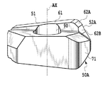
- the cutting insert (50) is formed in a plate shape, and a cutting edge is formed on an intersecting ridge line between at least one of the upper surface or the lower surface and the outer peripheral side surface, and the cutting blade includes an outer blade (51) and an outer edge.
- the first rake face that is formed so as to protrude from the second abutment surface (83), is inclined with respect to the second abutment surface (83), and is connected to the outer blade (51) (61) and the second rake connected to the first rake face (61), inclined in a direction different from the first rake face (61) and connected to the inner blade (52).
- the inner blade (52) is convexly curved.
- the amount of overlapping of the inner blades can be easily adjusted in a state where two or more inner blades face each other with the rotation axis interposed therebetween. Therefore, the degree of freedom of arrangement of the cutting insert is high. For this reason, it becomes possible to deal with tools having various drill diameters. Further, according to the present invention, since at least one inner blade of the two or more cutting inserts is convexly curved with respect to the rotation axis, chips formed at the center of the tool are laterally moved. It becomes easy to escape and can suppress clogging between cutting inserts.
- FIG. 7 is a cross-sectional view taken along a plane A that includes the axis AX of the cutting insert of FIG.
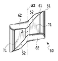
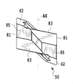
- the perspective view from one direction of the cutting insert of FIG. The perspective view from the other direction of the cutting insert of FIG.
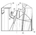
- the side view of the tool main body seen from the direction along the Y plane of FIG. The side view of the tool main body seen from the direction along X plane of FIG.
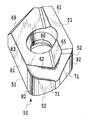
- the perspective view from the other direction of the tool main body of FIG. It is a front view which shows the 1st modification of the 1st Embodiment of this invention.
- FIG. 1 It is a front view which shows the 1st modification of the 1st Embodiment of this invention. It is a front view which shows the 2nd modification of the 1st Embodiment of this invention. It is a front view of the cutting insert used for the cutting tool of FIG.
- the front view of the cutting insert which concerns on the 2nd Embodiment of this invention.
- the bottom view of the cutting insert of FIG. The rear view of the cutting insert of FIG.
- the right view of the cutting insert of FIG. It is a perspective view of the bottom face side of the cutting insert of FIG. It is a perspective view from the other direction of the bottom face side of the cutting insert of FIG.
- the blade-tip-exchange-type rotary cutting tool is a rotary cutting tool capable of drilling, and is used as a drill, for example.
- “Perforating” means that cutting can be performed in a direction parallel to the rotation axis C of the rotary tool. That is, a cutting edge is required from the outer periphery to the vicinity of the rotation axis C at the tip portion of the rotary cutting tool.
- the cutting edge exchange type rotary cutting tool includes a tool main body 10 that can rotate around a rotation axis C extending in the longitudinal direction, and a rotational symmetry about the rotation axis C at a tip region of the tool main body 10 by approximately 180 degrees.
- the two cutting inserts 50 are negative type cutting inserts having the same shape.
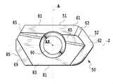
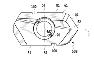
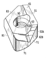
- the cutting insert 50 is formed in a plate shape and has first to third contact surfaces 81, 83 and 85. These three surfaces are in contact with first to third seat surfaces 21, 23, and 25 of the tool body 10, which will be described later.
- the first contact surface 81 is formed on the outer peripheral side surface of the cutting insert 50, and is two flat surfaces parallel to each other.
- the second contact surfaces 83 are formed on the upper surface and the lower surface of the cutting insert 50, respectively, and are parallel to each other.
- the third contact surface 85 is a surface formed at two locations on the outer peripheral side surface of the cutting insert 50.
- first to third contact surfaces 81, 83, 85 are not limited to flat surfaces, and may be curved surfaces in other embodiments. In other words, any surface may be used as long as it is in contact with the first to third seat surfaces 21, 23, 25 formed on the tool body 10.
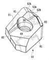
- the cutting insert 50 includes a through hole 90 for attaching the cutting insert.
- the through hole 90 is formed so as to penetrate the upper and lower surfaces, and has a central axis AX parallel to the first contact surface 81.
- a first rake face 61 is formed on the upper and lower surfaces of the cutting insert 50.
- the first rake face 61 is formed so as to protrude from the second contact surface 83, and is inclined with respect to the second contact surface 83. Specifically, as shown in FIG. 5, the first rake face 61 is inclined in a direction away from the cutting insert 50 from the left end side to the right end side of the cutting insert 50.
- the second rake face 62 is connected to a connection region 63 that is the most protruding portion of the first rake face 61, and is inclined with respect to the second abutting face 83 in a direction different from the first rake face 61. ing. Specifically, the second rake face 62 is inclined toward the bottom surface side of the cutting insert 50 as the distance from the connection region 63 increases. A part of the second rake face 62 intersects with the second contact face 83.
- connection region 63 When the first rake face 61 and the second rake face 62 are connected via the connection region 63, the shape of the cutting edge changes smoothly and the cutting insert becomes difficult to chip.
- the connection region 63 is not provided, and the first rake face 61 and the second rake face 62 may be directly connected. However, if the first rake face and the second rake face are directly connected, the ridgeline becomes a corner, which tends to cause the cutting insert to be chipped.
- the second rake face 83 is inclined.
- An inclined surface 65 is interposed.
- notched inclined surface portions 69 are formed on the upper and lower surfaces of the cutting insert 50 in order to prevent a part of the cutting insert 50 from projecting from the outer periphery of the tool body 10 and interfering with the workpiece after processing. Has been.
- the first contact surface 81 intersects with the first rake surface 61 and becomes a flank (first flank) of the outer blade 51 described later.
- the first contact surface 81 is smoothly connected to a connection surface 82 that is curved outward of the cutting insert 50, and the connection surface 82 is connected to a second flank 71 that intersects the second rake surface 62. It is connected.
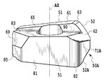
- the outer blade 51 that cuts the outer peripheral side during drilling and the inner blade 52 that cuts the central side are the outer peripheral surfaces connecting the first contact surface 81, the connection surface 82, and the second flank 71. And the first rake face 61, the rake face connection region 63, and the rake face connecting the second rake face 62.
- the outer blade 51 is a part of the intersecting ridge line portion between the first contact surface 81 and the first rake surface 61 and the intersecting ridge line portion between the connection surface 82 and the first rake surface 61.
- the part which is comprised and is extended substantially linearly from the outer peripheral side of the tool main body 10 corresponds.
- the inner blade 52 is constituted by a part of the intersecting ridge line portion between the connection surface 82 and the first rake face 61 and the intersecting ridge line portion between the second flank 71 and the second rake face 62.
- the part extending in a different direction corresponds to this. That is, the inner blade 52 corresponds to a portion extending from the side where the outer blade 51 is disposed to the X plane and the Y plane, crossing the X plane and the Y plane shown in FIG.
- the portion extending linearly from the right (left) outer periphery of the tool body 10 toward the rotation axis C is the outer blade 51, and the rotation axis is bent from the outer blade 51.
- the portion that passes in the vicinity of C is the inner blade 52.
- the X plane is defined as a plane that includes the rotation axis C and passes through the outermost end of any one of the outer blades 51 as a reference.
- the Y plane is defined as a plane that includes the rotation axis C and is orthogonal to the X plane.
- the cutting insert 50 is 180-degree rotationally symmetric with respect to an axis of symmetry J that is orthogonal to the central axis AX and parallel to the first contact surface 81. Therefore, the cutting insert 50 can be used twice upside down.
- the inner blade 52 which is an intersection of the second rake face 62 and the second flank 71, as viewed from the direction of the symmetry axis J, is directed toward the rotational axis C. Curved in a convex shape.
- the inner blade 52 is curved in a convex shape when viewed from the direction facing the second flank 71. As will be described later, this is a configuration for suppressing the clogging of chips into a narrow gap formed between the overlapping portions of the inner blades.
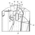
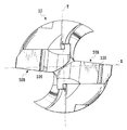
- the tool body 10 has two protrusions 11 at positions where its tip is 180 degrees rotationally symmetric with respect to the rotation axis C.
- the protrusion 11 is formed by cutting out the tip of the tool body 10 along the shape of the cutting insert 50.
- the two projecting portions 11 are formed with a first seat surface 21 with which the first abutting surface 81 of each cutting insert 50 abuts, and a screw hole penetrating the first seat surface 21. 40 is formed.
- the first seat surfaces 21 face each other across the rotation axis C and are parallel to the rotation axis C.
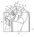
- the surface extending between the two protrusions 11 is a second seat surface 23 formed of an inclined surface (plane) that is rotationally symmetrical by 180 degrees with respect to the rotation axis C.
- the second seating surface 23 is inclined toward the rear end side of the tool body 10 as it goes radially outward from the rotation axis C side.
- the angle formed by the plane including the first seating surface 21 and the plane including the second seating surface 23 corresponding thereto is an acute angle.
- the third seating surface 25 is formed in the vicinity of the second seating surface 23 and is a flat surface inclined so as to face the second seating surface 23 side.
- the wall portion 26 that constitutes the third seating surface 25 and faces the outer peripheral direction of the tool main body 10 functions to protect the outer blade 51.
- a recess 30 having a concave curved surface extending along the first seat surface 21 is formed between the plane including the first seat surface 21 and the corresponding second seat surface 23.
- This recessed part 30 is for covering and protecting the one of the two cutting edges of the cutting insert 50 that is not used for cutting. By covering at least the outer blade 51 with the concave portion 30, it is possible to prevent the cutting blade that is not used during the cutting process from being damaged.
- the recess 30 is formed as a groove shape.
- the recessed part 30 can also be made into the shape which covers the whole cutting blade which is not used during cutting.
- two helical chip conveying grooves 15 are formed in the longitudinal direction on the outer peripheral surface of the tool body 10.
- the chip conveying groove 15 is continuous with a concave curved surface 24 adjacent to the second seat surface 23 shown in FIG. As shown in FIG. 13, the curved surface 24 is located immediately below the inner blade 52 in a direction parallel to the rotation axis C. By this curved surface 24, chips generated by the inner blade 52 are smoothly guided to the chip conveying groove 15.
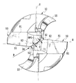
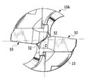
- the inner blades 52 of the two cutting inserts 50 are arranged so as to face each other across the rotation axis C when viewed from the tip, and are convex so that the tops of both inner blades 52 face the rotation axis C. It is curved. That is, when viewed from the tip, the two inner blades 51 are arranged at positions that are approximately 180 degrees rotationally symmetric with respect to the rotation axis C, and the interval GP1 between the inner blades 51 gradually increases as the distance from the rotation axis C increases in the radial direction. Has expanded to. Since the inner blades 52 of the two cutting inserts 50 face each other, a cylindrical non-cutting portion is formed between the two inner blades 52 during the cutting process.
- the interval GP2 between the second rake faces 62 that form the inner blades 52 of the two cutting inserts and that face each other is parallel to the rotation axis C. Is gradually enlarged toward the tool body 10 side. That is, the gap GP2 becomes wider from the front end side (upper drawing) of the tool main body 10 toward the rear end side (lower drawing) of the tool main body 10.
- the D direction is a direction along a plane passing through the rotation axis C between the second rake faces 62 facing each other and between the inner blades 52 facing each other.
- the “D direction” defined as described above is not limited to one, but the interval GP2 gradually increases toward the tool body 10 when viewed from all the directions defined as described above. It is formed to do.
- the two second flank surfaces 71 respectively forming the inner blades 52 of the two cutting inserts 50 are directed toward the rear end side of the tool body 10 toward the rear in the rotational direction of the rotary cutting tool. Inclined, and further toward the rear end side of the tool body 10 as it approaches the rotation axis C side.
- the gap GP1 is set as described above. Since it expands gradually as it leaves
- the two second flank surfaces 71 are inclined toward the rear end side of the tool body 10 as approaching the rotation axis C side, so It dents to the rear end side and does not interfere with the hole bottom.
- FIGS. 17A and 17B are a first modification of the first embodiment.
- the tools shown in FIGS. 17A and 17B are obtained by attaching common cutting inserts to different tool bodies 10A and 10B.
- the same reference numerals are used for the same components as those in the first embodiment.
- the tool diameter of the tool body 10B shown in FIG. 17B is larger than the tool diameter of the tool body 10A shown in FIG. 17A. That is, since the cutting insert 50 according to the present embodiment places the two inner blades 52 facing each other across the rotation axis C, the cutting of the outer blade 51 is performed within a range where the inner blades 52 face each other across the rotation axis C. You can change the maximum diameter possible.
- the inner blade 52 is curved in a convex shape, the range in which the two inner blades 52 can be opposed to each other with the rotation axis C interposed therebetween is greater than the case where the inner blade is linear. Is also wide.
- FIGS. 18 and 19 show a second modification of the first embodiment.
- the same reference numerals are used for the same components as those in the first embodiment.
- the chip splitter 100 is formed on the first contact surface 81 of each cutting insert 50B.
- the chip splitter 100 is also called a nickname.
- the chip splitter 100 is a concave groove formed in the first contact surface 81 and extends in the thickness direction of the cutting insert 50.
- the formation position of one chip splitter 100 and the formation position of the other chip splitter 100 are not 180-degree rotationally symmetric with respect to the symmetry axis J.
- the difference between the second embodiment and the first embodiment is the shape of the cutting insert.
- the two inner blades 52 and 52A of the cutting insert 50A according to the present embodiment have different shapes and are asymmetric with respect to the above-described symmetry axis J.
- the second rake face 62 having the same shape as that of the first embodiment is formed on the upper surface, and the shape of the second rake face 62 is formed on the lower surface.
- a different third rake face 62A is formed.
- the third rake face 62A is connected in the connection region 63 of the first rake face 61, and is inclined in a direction different from that of the first rake face 61 and curved in a concave shape.
- a fourth rake face 62B is formed adjacent to the third rake face 62A, which is a flat surface.
- a second flank 71 intersecting with the second rake face 62 and a third flank 71A having a different shape from the second flank 71 intersecting with the third rake face 62A are formed on the side surfaces.
- the 1st inner blade 52 of the same shape as the inner blade of 1st Embodiment is formed in the intersection of the 2nd rake face 62 and the 2nd flank 71, and the 3rd rake face 62A and A second inner blade 52A having a shape different from that of the first inner blade 52 is formed at the intersection with the third flank 71A and at the intersection between the fourth rake face 62B and the third flank 71A. ing.
- the first inner blade 52 is curved in a convex shape toward the rotation axis C as seen from the direction of the symmetry axis J.
- the inner blade 52A is formed of a concavely curved portion and a linear portion when viewed from the direction of the symmetry axis J. That is, by making the shape of the third rake face 62A different from the shape of the fourth rake face 62B, the second inner blade 52A is formed by a curve curved in a concave shape with respect to the straight line and the rotation axis C. .
- the shortest distance from the second inner blade 52A to the rotation axis C is longer than the distance from the first inner blade 51 to the rotation axis C. That is, the second inner blade 52A is offset in the radial direction, and is disposed on the radially outer side than the first inner blade 52.
- the diameter of the cylindrical chip formed at the center of the tool is the same as that of the first inner blade 51. It is defined by the distance from the rotation axis C. For this reason, a gap is formed between the offset second inner blade 52A and the cylindrical chip. As a result, chips are less likely to be clogged between the first inner blade 51 and the second inner blade 52A.
- the cylindrical chip formed in the center part of the blade-tip-exchange-type rotary cutting tool of the present embodiment receives force only from the first inner blade 51, the cylindrical chip, particularly the cylindrical non-cutting A bending force to be folded can always be applied to the part. Thereby, columnar chips are easily discharged in the outer peripheral direction of the tool body 10.
- a feed is given in the rotational axis direction such as a plunging tool or an end mill with a bottom blade.
- any tool that cuts can be used.
- both inner blades have the same shape, but when both inner blades are convex curves and one inner blade is compared with the other inner blade, one inner blade It is also possible to adopt a shape in which the shortest distance from the rotation axis to the rotation axis is longer than the shortest distance on the other side.
- each of the two blades is used.
- the blade-tip-exchange-type rotary cutting tool of the present invention can be structured to have three or more cutting inserts.
- the outer blade was also a straight line in the above embodiment, but it may be formed in a concave curve shape that curves in the direction in which the thickness of the cutting insert decreases.
- a force to bend the generated chip from the side can be generated, so that the chip is easily subdivided.
- the inner blade and the inner blade face each other across the rotation axis means that the inner blades are close to each other to the extent that they function as a cutting edge-exchangeable rotary cutting tool, and the gap formed by the two inner blades That is, at least one of the openings is formed to spread from the center toward the outer periphery.
- “in the vicinity of the rotation axis C” means that the inner blade is close to the rotation axis C to such an extent that it functions as a cutting edge of a blade cutting type rotary cutting tool capable of drilling.
Landscapes
- Engineering & Computer Science (AREA)
- Mechanical Engineering (AREA)
- Drilling Tools (AREA)
- Milling Processes (AREA)
Abstract
L'invention porte sur une plaquette de coupe rotative indexable et sur des plaquettes de coupe qui sont utilisées dans l'outil de coupe rotatif indexable, qui peuvent éviter que les copeaux ne provoquent des blocages entre deux plaquettes de coupe. La plaquette de coupe (50) présente un corps d'outil (10) qui peut tourner autour d'un axe de rotation (C), et des plaquettes de coupe (50) qui sont attachées de façon démontable à la zone de pointe du corps d'outil (10). Les plaquettes de coupe (50) ont au moins deux positions de rotation présentant une symétrie de révolution par rapport à l'axe de rotation (C). Chaque plaquette de coupe (50) comprend une lame extérieure (51) qui s'étend du côté de l'axe de rotation (C) jusqu'au côté circonférentiel extérieur, et une lame intérieure (52) qui rejoint la lame extérieure (51) et qui est positionnée sur le côté de l'axe de rotation (C). Vu du côté de pointe de l'outil, au moins les lames intérieures (52) des plaquettes de coupe (50) sont incurvées avec une forme convexe par rapport à l'axe de rotation (C).
Applications Claiming Priority (2)
| Application Number | Priority Date | Filing Date | Title |
|---|---|---|---|
| JP2011-164417 | 2011-07-27 | ||
| JP2011164417A JP2014193491A (ja) | 2011-07-27 | 2011-07-27 | 刃先交換式回転切削工具およびこれに用いる切削インサート |
Publications (1)
| Publication Number | Publication Date |
|---|---|
| WO2013015404A1 true WO2013015404A1 (fr) | 2013-01-31 |
Family
ID=47601235
Family Applications (1)
| Application Number | Title | Priority Date | Filing Date |
|---|---|---|---|
| PCT/JP2012/069107 Ceased WO2013015404A1 (fr) | 2011-07-27 | 2012-07-27 | Outil de coupe rotatif indexable et plaquette de coupe utilisée dans cet outil |
Country Status (2)
| Country | Link |
|---|---|
| JP (1) | JP2014193491A (fr) |
| WO (1) | WO2013015404A1 (fr) |
Cited By (2)
| Publication number | Priority date | Publication date | Assignee | Title |
|---|---|---|---|---|
| WO2016084898A1 (fr) * | 2014-11-27 | 2016-06-02 | 株式会社タンガロイ | Insert de coupe, corps d'outil et outil de coupe |
| CN109158665A (zh) * | 2018-08-14 | 2019-01-08 | 株洲钻石切削刀具股份有限公司 | 可转位钻孔刀具 |
Citations (4)
| Publication number | Priority date | Publication date | Assignee | Title |
|---|---|---|---|---|
| JPH11291102A (ja) * | 1998-04-08 | 1999-10-26 | Mitsubishi Materials Corp | スローアウェイチップおよび該スローアウェイチップを装着したスローアウェイ式ドリル |
| JP2000094210A (ja) * | 1998-09-28 | 2000-04-04 | Mitsubishi Materials Corp | スローアウェイ式穴明け工具 |
| JP2000158220A (ja) * | 1998-11-30 | 2000-06-13 | Ngk Spark Plug Co Ltd | スローアウェイドリル及びそのシャンク |
| JP2010523353A (ja) * | 2007-04-01 | 2010-07-15 | イスカーリミテッド | 切削インサート |
-
2011
- 2011-07-27 JP JP2011164417A patent/JP2014193491A/ja not_active Withdrawn
-
2012
- 2012-07-27 WO PCT/JP2012/069107 patent/WO2013015404A1/fr not_active Ceased
Patent Citations (4)
| Publication number | Priority date | Publication date | Assignee | Title |
|---|---|---|---|---|
| JPH11291102A (ja) * | 1998-04-08 | 1999-10-26 | Mitsubishi Materials Corp | スローアウェイチップおよび該スローアウェイチップを装着したスローアウェイ式ドリル |
| JP2000094210A (ja) * | 1998-09-28 | 2000-04-04 | Mitsubishi Materials Corp | スローアウェイ式穴明け工具 |
| JP2000158220A (ja) * | 1998-11-30 | 2000-06-13 | Ngk Spark Plug Co Ltd | スローアウェイドリル及びそのシャンク |
| JP2010523353A (ja) * | 2007-04-01 | 2010-07-15 | イスカーリミテッド | 切削インサート |
Cited By (5)
| Publication number | Priority date | Publication date | Assignee | Title |
|---|---|---|---|---|
| WO2016084898A1 (fr) * | 2014-11-27 | 2016-06-02 | 株式会社タンガロイ | Insert de coupe, corps d'outil et outil de coupe |
| JP5991565B1 (ja) * | 2014-11-27 | 2016-09-14 | 株式会社タンガロイ | 切削インサート、工具ボデーおよび切削工具 |
| CN107000081A (zh) * | 2014-11-27 | 2017-08-01 | 株式会社泰珂洛 | 切削刀片、工具体及切削工具 |
| CN109158665A (zh) * | 2018-08-14 | 2019-01-08 | 株洲钻石切削刀具股份有限公司 | 可转位钻孔刀具 |
| CN109158665B (zh) * | 2018-08-14 | 2020-02-04 | 株洲钻石切削刀具股份有限公司 | 可转位钻孔刀具 |
Also Published As
| Publication number | Publication date |
|---|---|
| JP2014193491A (ja) | 2014-10-09 |
Similar Documents
| Publication | Publication Date | Title |
|---|---|---|
| JP5070225B2 (ja) | 切削インサート、特にドリル用スローアウェイチップ | |
| JP6580572B2 (ja) | 割出し可能な両面切削インサートおよびそれ用の切削工具 | |
| JP6532940B2 (ja) | 両面型切削インサートおよびフライス工具 | |
| JP5679042B2 (ja) | ガイドパッド、切削工具本体および切削工具 | |
| JP5939355B2 (ja) | 切削インサート及び刃先交換式切削工具 | |
| JP6436093B2 (ja) | 切削インサート及び刃先交換式切削工具 | |
| WO2011046121A1 (fr) | Plaquette de coupe et outil tournant avec arête de lame interchangeable | |
| JP2018534159A (ja) | 旋削インサートおよび方法 | |
| WO2016140333A1 (fr) | Insert de coupe, et outil de coupe rotatif à bord de coupe remplaçable | |
| CN105813785B (zh) | 刀头更换式旋转切削工具 | |
| JP5196077B2 (ja) | 切削用インサートおよび刃先交換式転削工具 | |
| JP6361948B2 (ja) | 切削インサートおよび切削工具 | |
| JPWO2016017780A1 (ja) | 切削インサートおよび刃先交換式切削工具 | |
| JP4125909B2 (ja) | スクエアエンドミル | |
| JP5988010B2 (ja) | 切削インサート、工具ボデーおよび切削工具 | |
| WO2013015404A1 (fr) | Outil de coupe rotatif indexable et plaquette de coupe utilisée dans cet outil | |
| JP6292425B2 (ja) | 刃先交換式回転切削工具 | |
| JP2015196203A (ja) | 刃先交換式メタルソー | |
| JP2009226509A (ja) | エンドミル | |
| JP2008018491A (ja) | サイドカッタ | |
| JPH0433565B2 (fr) | ||
| JP7242997B2 (ja) | 刃先交換式エンドミルのエンドミル本体 | |
| JP2022122825A (ja) | 切削インサートおよびこれを備えた切削工具 | |
| JP2021062424A (ja) | 切削工具および切削方法 | |
| JP4961841B2 (ja) | 中ぐり工具 |
Legal Events
| Date | Code | Title | Description |
|---|---|---|---|
| 121 | Ep: the epo has been informed by wipo that ep was designated in this application |
Ref document number: 12817592 Country of ref document: EP Kind code of ref document: A1 |
|
| NENP | Non-entry into the national phase |
Ref country code: DE |
|
| 122 | Ep: pct application non-entry in european phase |
Ref document number: 12817592 Country of ref document: EP Kind code of ref document: A1 |
|
| NENP | Non-entry into the national phase |
Ref country code: JP |