WO2013015426A1 - Dispositif de perçage - Google Patents
Dispositif de perçage Download PDFInfo
- Publication number
- WO2013015426A1 WO2013015426A1 PCT/JP2012/069245 JP2012069245W WO2013015426A1 WO 2013015426 A1 WO2013015426 A1 WO 2013015426A1 JP 2012069245 W JP2012069245 W JP 2012069245W WO 2013015426 A1 WO2013015426 A1 WO 2013015426A1
- Authority
- WO
- WIPO (PCT)
- Prior art keywords
- wedge plate
- deflection
- sleeve
- boring
- plate
- Prior art date
- Legal status (The legal status is an assumption and is not a legal conclusion. Google has not performed a legal analysis and makes no representation as to the accuracy of the status listed.)
- Ceased
Links
Images




Classifications
-
- B—PERFORMING OPERATIONS; TRANSPORTING
- B23—MACHINE TOOLS; METAL-WORKING NOT OTHERWISE PROVIDED FOR
- B23B—TURNING; BORING
- B23B29/00—Holders for non-rotary cutting tools; Boring bars or boring heads; Accessories for tool holders
- B23B29/03—Boring heads
-
- B—PERFORMING OPERATIONS; TRANSPORTING
- B23—MACHINE TOOLS; METAL-WORKING NOT OTHERWISE PROVIDED FOR
- B23B—TURNING; BORING
- B23B29/00—Holders for non-rotary cutting tools; Boring bars or boring heads; Accessories for tool holders
- B23B29/03—Boring heads
- B23B29/034—Boring heads with tools moving radially, e.g. for making chamfers or undercuttings
- B23B29/03432—Boring heads with tools moving radially, e.g. for making chamfers or undercuttings radially adjustable during manufacturing
- B23B29/03489—Adjustment means not specified or not covered by the groups B23B29/03435 - B23B29/03478
-
- B—PERFORMING OPERATIONS; TRANSPORTING
- B23—MACHINE TOOLS; METAL-WORKING NOT OTHERWISE PROVIDED FOR
- B23B—TURNING; BORING
- B23B29/00—Holders for non-rotary cutting tools; Boring bars or boring heads; Accessories for tool holders
- B23B29/02—Boring bars
-
- B—PERFORMING OPERATIONS; TRANSPORTING
- B23—MACHINE TOOLS; METAL-WORKING NOT OTHERWISE PROVIDED FOR
- B23B—TURNING; BORING
- B23B29/00—Holders for non-rotary cutting tools; Boring bars or boring heads; Accessories for tool holders
- B23B29/03—Boring heads
- B23B29/034—Boring heads with tools moving radially, e.g. for making chamfers or undercuttings
-
- B—PERFORMING OPERATIONS; TRANSPORTING
- B23—MACHINE TOOLS; METAL-WORKING NOT OTHERWISE PROVIDED FOR
- B23Q—DETAILS, COMPONENTS, OR ACCESSORIES FOR MACHINE TOOLS, e.g. ARRANGEMENTS FOR COPYING OR CONTROLLING; MACHINE TOOLS IN GENERAL CHARACTERISED BY THE CONSTRUCTION OF PARTICULAR DETAILS OR COMPONENTS; COMBINATIONS OR ASSOCIATIONS OF METAL-WORKING MACHINES, NOT DIRECTED TO A PARTICULAR RESULT
- B23Q5/00—Driving or feeding mechanisms; Control arrangements therefor
- B23Q5/02—Driving main working members
- B23Q5/04—Driving main working members rotary shafts, e.g. working-spindles
- B23Q5/043—Accessories for spindle drives
- B23Q5/045—Angle drives
-
- Y—GENERAL TAGGING OF NEW TECHNOLOGICAL DEVELOPMENTS; GENERAL TAGGING OF CROSS-SECTIONAL TECHNOLOGIES SPANNING OVER SEVERAL SECTIONS OF THE IPC; TECHNICAL SUBJECTS COVERED BY FORMER USPC CROSS-REFERENCE ART COLLECTIONS [XRACs] AND DIGESTS
- Y10—TECHNICAL SUBJECTS COVERED BY FORMER USPC
- Y10T—TECHNICAL SUBJECTS COVERED BY FORMER US CLASSIFICATION
- Y10T279/00—Chucks or sockets
- Y10T279/14—Eccentric
-
- Y—GENERAL TAGGING OF NEW TECHNOLOGICAL DEVELOPMENTS; GENERAL TAGGING OF CROSS-SECTIONAL TECHNOLOGIES SPANNING OVER SEVERAL SECTIONS OF THE IPC; TECHNICAL SUBJECTS COVERED BY FORMER USPC CROSS-REFERENCE ART COLLECTIONS [XRACs] AND DIGESTS
- Y10—TECHNICAL SUBJECTS COVERED BY FORMER USPC
- Y10T—TECHNICAL SUBJECTS COVERED BY FORMER US CLASSIFICATION
- Y10T408/00—Cutting by use of rotating axially moving tool
- Y10T408/83—Tool-support with means to move Tool relative to tool-support
- Y10T408/85—Tool-support with means to move Tool relative to tool-support to move radially
-
- Y—GENERAL TAGGING OF NEW TECHNOLOGICAL DEVELOPMENTS; GENERAL TAGGING OF CROSS-SECTIONAL TECHNOLOGIES SPANNING OVER SEVERAL SECTIONS OF THE IPC; TECHNICAL SUBJECTS COVERED BY FORMER USPC CROSS-REFERENCE ART COLLECTIONS [XRACs] AND DIGESTS
- Y10—TECHNICAL SUBJECTS COVERED BY FORMER USPC
- Y10T—TECHNICAL SUBJECTS COVERED BY FORMER US CLASSIFICATION
- Y10T408/00—Cutting by use of rotating axially moving tool
- Y10T408/91—Machine frame
Definitions
- the present invention relates to a boring apparatus.
- the present invention relates to a boring apparatus capable of boring a large workpiece and machining a surface perpendicular to the axis of the boring hole.
- FIG. 9 shows a conventional boring apparatus 100 for boring a large workpiece.
- the boring apparatus 100 includes a guide rail 120 that extends linearly in one direction, an apparatus main body 130 that is slidably movable on the guide rail 120, and a substantially parallel to the guide rail 120 that comes out of the apparatus main body 130.
- a sleeve 140 extending in a plane, and a rotating face plate 160 attached to the tip of the sleeve 140.
- a cutting tool 165 is attached to the rotating face plate 160.
- the cutting tool 165 rotates with the rotation of the rotating face plate 160, whereby boring is performed.
- the rotating face plate 160 is provided with a cutting tool 168 on the side facing the cutting tool 165.
- the cutting tool 165 is provided on the rotating face plate 160 via a U-axis control mechanism that expands and contracts in the radial direction of the rotating face plate 160. In this case, it is easy to process a surface perpendicular to the axis of the boring hole as desired.
- the sleeve 140 is supported on the apparatus main body 130 by a cantilever structure. For this reason, the sleeve 140 is slightly bent by gravity (for example, about tan ⁇ 1 (0.24 / 1000)). Due to the bending, the trajectory of the cutting tool 165 of the rotating face plate 160 attached to the distal end portion of the sleeve 140 is slightly removed from the vertical plane. For this reason, in the conventional boring apparatus 100, when boring is performed by moving the apparatus main body 130 along the guide rail 120, a surface perpendicular to the axis of the boring hole is processed with high accuracy. I can't.
- An object of the present invention is to provide a boring apparatus capable of boring a large workpiece and machining a plane perpendicular to the axis of the boring hole with high accuracy.
- the present invention relates to a guide rail that extends linearly in one direction, a device main body that is slidably mounted on the guide rail, and an in-plane substantially parallel to the guide rail that exits from the device main body. And a rotating face plate attached to the distal end portion of the sleeve, wherein a deflection compensating wedge plate is provided between the distal end portion of the sleeve and the rotating face plate.
- a boring apparatus characterized by that.
- the rotating face plate can be made perpendicular to the axis of the boring hole. . Therefore, a plane perpendicular to the axis of the boring hole can be processed with high accuracy.
- the wedge compensating wedge plate has a shape obtained by obliquely cutting a cylinder or a polygonal column.
- the cutting angle (inclination angle) is determined according to the assumed amount of bending of the sleeve.
- the wedge plate for deflection compensation is provided such that a straight line connecting the thinnest part and the thickest part is aligned in the vertical direction. In this case, there is no horizontal shift in the rotating face plate.
- the deflection compensating wedge plate may be provided by shifting (rotating) a straight line connecting the thinnest part and the thickest part from the vertical direction by a predetermined angle.
- the deflection compensating wedge plate may be provided by shifting (rotating) a straight line connecting the thinnest part and the thickest part from the vertical direction by a predetermined angle.
- the deflection of the sleeve can be compensated with higher accuracy.
- the maximum inclination angle (based on the thinnest part and the thickest part) of the deflection compensating wedge plate is formed to be larger than the assumed bending angle of the sleeve. It is necessary to keep.
- Any desired angle less than the maximum inclination angle can be compensated for the deflection of the sleeve in the vertical direction by installing the deflection compensating wedge plate having such a maximum inclination angle by shifting (rotating) it by an appropriate angle. Can be used.
- the deflection compensating wedge plate when installed by being shifted (rotated) by an appropriate angle, it is projected within the horizontal plane of the rotation axis of the rotary face plate relative to the guide rail (when viewed in plan; projected onto the horizontal plane). There will be a “shift” in the angle (when viewed).
- the angle of the sleeve with respect to the guide rail in the horizontal plane can be changed in the horizontal plane depending on the interposed state of the deflection compensating wedge plate. It is preferable.
- the deflection compensating wedge plate of the boring apparatus includes a first half deflection compensating wedge plate and a second half deflection compensating wedge plate having the same inclination angle.
- the degree of freedom of adjustment work can be increased.
- the first half deflection compensating wedge plate is provided such that a straight line connecting the thinnest portion and the thickest portion is shifted (rotated) to the right by a predetermined angle from the vertical direction.
- the second half deflection compensating wedge plate is provided such that a straight line connecting the thinnest part and the thickest part is shifted (rotated) from the vertical direction to the left rotation direction by the predetermined angle. If such a form is adopted, it is possible to avoid the horizontal displacement of the rotating face plate, and thus the horizontal adjustment work of the rotating face plate is unnecessary.
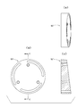
- FIG. 1 is a schematic perspective view of a boring apparatus according to a first embodiment of the present invention. It is a schematic side view of the rotating face plate vicinity of the boring apparatus of FIG. It is the schematic which shows an example of the wedge board for bending compensation, (a) is a top view, (b) is a front view, (c) is a side view. It is the schematic which shows the other example of the wedge board for bending compensation, (a) is a top view, (b) is a front view, (c) is a side view. It is the schematic which shows the other example of the wedge board for bending
- FIG. 5 is a side view of the second half deflection compensating wedge plate.
- FIG. 8 is a schematic side view of the vicinity of a rotating face plate when the deflection compensating wedge plate of FIG. 7 is used. It is a schematic perspective view of the conventional boring apparatus.
- FIG. 1 is a schematic perspective view of a boring apparatus according to a first embodiment of the present invention.
- FIG. 2 is a schematic side view of the vicinity of the rotating face plate of the boring apparatus of FIG.
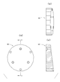
- FIG. 3 is a schematic view showing an example of a wedge plate for deflection compensation.
- a boring apparatus 10 includes a guide rail 20 that extends linearly in one direction, an apparatus main body 30 that is slidably mounted on the guide rail 20, and an apparatus.
- a sleeve 40 extending from the main body 30 and extending in a plane substantially parallel to the guide rail 20, and a rotating face plate 60 attached to the tip of the sleeve 40 are provided.
- a cutting tool 65 is attached to the rotating face plate 60.
- the cutting tool 65 rotates with the rotation of the rotating face plate 60, so that boring can be performed.
- the rotary face plate 60 is provided with a cutting tool 68 on the side facing the cutting tool 65.
- the cutting tool 65 is attached to the rotating surface plate 60 via a U-axis control mechanism that expands and contracts in the radial direction of the rotating surface plate 60. Thereby, it is facilitated to process a surface perpendicular to the axis of the boring hole as desired.
- the boring apparatus 10 has a deflection compensating wedge plate 50 between the tip of the sleeve 40 and the rotating face plate 60 as a feature of the present invention. is doing.
- the deflection compensating wedge plate 50 is a member having an attachment surface connected to the sleeve 40 and an attachment surface connected to the rotating surface plate 60 on the side facing the surface. is there. 3 has a shape obtained by obliquely cutting a cylinder.
- FIG. 4 it is also possible to use a deflection compensating wedge plate having a shape obtained by obliquely cutting a polygonal column.
- the cutting angle (inclination angle) is determined in accordance with the amount of bending after an expected amount of bending of the sleeve 140 is determined in advance by measurement or the like.
- the inclination angle of the deflection compensating wedge plate 50 is exaggerated in each drawing.
- the deflection compensating wedge plate 50 and the sleeve 40 For connecting the deflection compensating wedge plate 50 and the sleeve 40 and connecting the deflection compensating wedge plate 50 and the rotating face plate 60, various connecting means known per se can be employed.
- fastening with bolts is employed.
- the bending compensation wedge plate 50 is provided with a plurality of through holes for fastening bolts, and female screw holes are provided at corresponding portions of the sleeve 40 and the rotating face plate 60.
- the rotating face plate 60 has a smaller diameter than the sleeve 40, so the deflection compensating wedge plate 50 is first connected to the rotating face plate 60 with fastening bolts, Thereafter, the connecting body is connected to the sleeve 40 with a fastening bolt.
- the bending compensation wedge plate 50 of the present embodiment is provided so that the straight line connecting the thinnest part and the thickest part is aligned in the vertical direction. As a result, no horizontal displacement occurs in the rotation axis of the rotating face plate 60.
- the boring apparatus 10 of this embodiment assembled as shown in FIGS. 1 and 2 operates as follows.
- the apparatus main body 30 slides on the guide rail 20, and the sleeve 40 is inserted into a prepared hole (for example, a large workpiece) to be bored.
- a prepared hole for example, a large workpiece
- the rotary face plate 60 is rotationally driven, and the boring processing by the cutting tool 65 is performed.
- the cutting tool 65 is preferably U-axis controlled by an appropriate NC control method.
- processing of a surface perpendicular to the axis of the boring hole can be performed.
- the cutting trajectory of the cutting tool 65 can be made exactly perpendicular to the axis of the boring hole. For this reason, processing of a surface perpendicular to the axis of the boring hole can be performed with extremely high accuracy.
- the deflection compensating wedge plate 50 of the present embodiment is provided so that the straight line connecting the thinnest part and the thickest part is aligned in the vertical direction. There is no deviation.
- the deflection of the sleeve 40 can be compensated for by the deflection compensating wedge plate 50 provided between the distal end portion of the sleeve 40 and the rotating face plate 60.
- the deflection compensating wedge plate 50 provided between the distal end portion of the sleeve 40 and the rotating face plate 60.
- a plane perpendicular to the surface can be processed with high accuracy. Further, there is no inconvenience due to the provision of the bending compensation wedge plate 50.
- the inclination angle of the deflection compensating wedge plate 50 is determined according to the assumed amount of deflection of the sleeve 140, and the straight line connecting the thinnest part and the thickest part is aligned in the vertical direction. It is provided as follows.
- the bending compensation wedge plate 50 ′ may be provided such that a straight line connecting the thinnest part and the thickest part is shifted (rotated) by a predetermined angle from the vertical direction. If the deflection compensating wedge plate 50 ′ can be installed by being shifted (rotated) by an appropriate angle as described above, the deflection of the sleeve 40 can be compensated with higher accuracy in the field.
- the maximum inclination angle (based on the thinnest part and the thickest part) of the deflection compensating wedge plate 50 ′ is set larger than the assumed bending angle of the sleeve 40. It is necessary to form.
- the deflection compensating wedge plate 50 ′ having such a maximum inclination angle by shifting (rotating) it by an appropriate angle, when compensating the deflection of the sleeve 40 in the vertical direction, an arbitrary value less than the maximum inclination angle can be obtained. Any desired angle can be utilized.
- FIG. 5 is a schematic view showing an example of such a deflection compensating wedge plate.
- the bending compensation wedge plate 50 is provided with a plurality of through holes for fastening bolts (the cross section is T-shaped to accommodate the bolt head), and female screw holes (substantially equidistantly spaced) at corresponding locations of the sleeve 40 and the rotating face plate 60. Many: only some of them are used as appropriate).
- the through holes for connection to the sleeve 40 (outside) are each formed as an arc-shaped long hole. The elongated hole allows the deflection compensating wedge plate 50 'to be connected to the sleeve 40 at an arbitrary rotation angle.
- the rotating face plate 60 is smaller in diameter than the sleeve 40, and the deflection compensating wedge plate 50 ′ is first connected to the rotating face plate 60 with fastening bolts, and then the connected body is The sleeve 40 is connected with a fastening bolt after the rotation angle is adjusted through the elongated hole.
- the deflection compensating wedge plate 50 ′ as shown in FIG. 5 when the deflection compensating wedge plate 50 ′ as shown in FIG. 5 is installed by being shifted (rotated) by an appropriate angle, the rotation axis of the rotary face plate 60 with respect to the guide rail 20 in the horizontal plane (plane There is a “deviation” in the angle (when viewed; projected onto the horizontal plane).
- the angle of the sleeve 40 with respect to the guide rail 60 in the horizontal plane can be changed in the horizontal plane depending on the interposed state of the deflection compensating wedge plate 50 ′. It is preferable. An embodiment in which such a configuration is employed will be described with reference to FIG.
- FIG. 6 is a schematic plan view of a boring apparatus according to the second embodiment of the present invention.
- the apparatus main body 30 is positioned relative to the guide rail 20 in order to change the angle of the sleeve 40 with respect to the guide rail 20 in the horizontal plane.
- the installation base 21 is installed so as to be able to rotate around the fulcrum pin 22 with respect to the guide rail 20.
- the rotation state of the installation base 21 is positioned at a desired position by the positioning block 23, the positioning bolt 24 and the positioning bolt 25. Then, by rotating (that is, moving) each of the bolts 24 and 25 with respect to the positioning block 23, the rotation position around the fulcrum pin 22 of the installation base 21 can be adjusted.
- the deflection compensating wedge plate 50 ′ is installed with being shifted (rotated) by an appropriate angle, and the angle in the horizontal plane of the rotation axis of the rotary face plate 60 with respect to the guide rail 20.
- the bolts 24 and 25 are rotated to compensate for such “displacement”, and the rotation position around the fulcrum pin 22 of the installation base 21 is adjusted, so that the apparatus main body portion
- the direction of 30 and the sleeve 40 from the guide rail 20 (the extending direction thereof), it is possible to compensate for the angle deviation in the horizontal plane of the rotation axis of the rotary face plate 60 with respect to the guide rail 20.
- FIG. 7 is a schematic view showing an example of a deflection compensating wedge plate including a first half deflection compensating wedge plate 51 and a second half deflection compensating wedge plate 52.
- FIG. A side view of the wedge plate for deflection compensation (b) is a front view of the wedge plate for first half deflection compensation, (c) is a front view of the wedge plate for second half deflection compensation, and (d) is a second half deflection compensation. It is a side view of a wedge plate.
- FIG. 8 is a schematic side view of the vicinity of the rotating face plate when the wedge compensating wedge plate of FIG. 7 is used.
- the deflection compensating wedge plate includes a first half deflection compensating wedge plate 51 and a second half deflection compensating wedge plate 52 having the same inclination angle (maximum inclination angle). ing.
- the degree of freedom of adjustment work can be increased.
- the first half deflection compensating wedge plate 51 is configured such that the straight line connecting the thinnest part and the thickest part is shifted from the vertical direction by a predetermined angle in the right rotation direction (or left rotation direction)
- the second half deflection compensation wedge plate 52 is arranged such that the straight line connecting the thinnest part and the thickest part is shifted from the vertical direction to the left rotation direction (or right rotation direction) by the predetermined angle. (Rotated). If such a form is adopted, it is possible to avoid the occurrence of a horizontal shift in the rotation axis of the rotary face plate 60, and thus the horizontal adjustment work of the rotary face plate 60 is unnecessary. That is, it is not necessary to mount the function or configuration described with reference to FIG.
- each of the deflection compensating wedge plates 51 and 52 and the sleeve 40 and each of the deflection compensating wedge plates 51 and 52 and the rotating surface plate 60 are connected by bolts.
- Fastening is employed, and each of the deflection compensating wedge plates 51 and 52 is provided with a plurality of through holes for fastening bolts (the cross section is T-shaped to accommodate the bolt head).
- Female screw holes are provided at corresponding locations.
- each through hole of each of the deflection compensating wedge plates 51 and 52 is formed as an arc-shaped long hole. With these long holes, each of the deflection compensating wedge plates 51 and 52 can be connected to the sleeve 40 and the rotation surface portion 60 at an arbitrary rotation angle.
- the rotating face plate 60 has a smaller diameter than the sleeve 40, and each of the deflection compensating wedge plates 51 and 52 is a straight line connecting the thinnest part and the thickest part.
- the coupling body is temporarily fixed to the sleeve 40 while adjusting the rotation angle through the elongated hole.
- one of the first deflection compensation wedge plate 51 and the second deflection compensation wedge plate 52 is rotated in the opposite direction from the vertical direction by the same angle as the rotation angle at the time of the temporary fixing with respect to the vertical direction (first The other one of the deflection compensating wedge plate 51 and the second deflection compensating wedge plate 52 is maintained at the rotation angle at the time of temporary fixing).
- the final connection (fixation) with the fastening bolt is performed.
Landscapes
- Engineering & Computer Science (AREA)
- Mechanical Engineering (AREA)
- Processing Of Stones Or Stones Resemblance Materials (AREA)
- Drilling And Boring (AREA)
- Life Sciences & Earth Sciences (AREA)
- Geology (AREA)
- Mining & Mineral Resources (AREA)
- Physics & Mathematics (AREA)
- Environmental & Geological Engineering (AREA)
- Fluid Mechanics (AREA)
- General Life Sciences & Earth Sciences (AREA)
- Geochemistry & Mineralogy (AREA)
Abstract
Priority Applications (4)
| Application Number | Priority Date | Filing Date | Title |
|---|---|---|---|
| JP2013525787A JP5905465B2 (ja) | 2011-07-28 | 2012-07-27 | ボーリング加工装置 |
| US14/235,345 US9914175B2 (en) | 2011-07-28 | 2012-07-27 | Boring machine |
| CN201280037762.8A CN103796780B (zh) | 2011-07-28 | 2012-07-27 | 镗床 |
| KR1020147002235A KR101527695B1 (ko) | 2011-07-28 | 2012-07-27 | 보링 가공 장치 |
Applications Claiming Priority (2)
| Application Number | Priority Date | Filing Date | Title |
|---|---|---|---|
| JP2011165638 | 2011-07-28 | ||
| JP2011-165638 | 2011-07-28 |
Publications (1)
| Publication Number | Publication Date |
|---|---|
| WO2013015426A1 true WO2013015426A1 (fr) | 2013-01-31 |
Family
ID=47601256
Family Applications (1)
| Application Number | Title | Priority Date | Filing Date |
|---|---|---|---|
| PCT/JP2012/069245 Ceased WO2013015426A1 (fr) | 2011-07-28 | 2012-07-27 | Dispositif de perçage |
Country Status (5)
| Country | Link |
|---|---|
| US (1) | US9914175B2 (fr) |
| JP (1) | JP5905465B2 (fr) |
| KR (1) | KR101527695B1 (fr) |
| CN (1) | CN103796780B (fr) |
| WO (1) | WO2013015426A1 (fr) |
Families Citing this family (2)
| Publication number | Priority date | Publication date | Assignee | Title |
|---|---|---|---|---|
| US9649695B1 (en) * | 2016-03-10 | 2017-05-16 | Meridian Equipment, Inc. | Automated cross slide system |
| CN114703764B (zh) * | 2022-06-07 | 2022-09-06 | 中铁三局集团有限公司 | 一种高铁倾斜箱梁调平移位施工方法 |
Citations (3)
| Publication number | Priority date | Publication date | Assignee | Title |
|---|---|---|---|---|
| JPH0166914U (fr) * | 1987-10-26 | 1989-04-28 | ||
| JP2011031357A (ja) * | 2009-08-04 | 2011-02-17 | Toshiba Mach Co Ltd | 深穴加工方法および深穴加工装置 |
| JP2012030344A (ja) * | 2010-07-29 | 2012-02-16 | Nt Engineering Kk | 加工装置 |
Family Cites Families (32)
| Publication number | Priority date | Publication date | Assignee | Title |
|---|---|---|---|---|
| US2223041A (en) * | 1937-12-29 | 1940-11-26 | Westinghouse Air Brake Co | Boring head |
| US2257402A (en) * | 1939-05-01 | 1941-09-30 | Heald Machine Co | Retracting mechanism for boring tools |
| US2263085A (en) * | 1939-05-22 | 1941-11-18 | Heald Machine Co | Retracting mechanism for boring tools |
| US2231511A (en) * | 1939-05-24 | 1941-02-11 | Heald Machine Co | Tool retracting mechanism |
| US2277950A (en) * | 1939-06-23 | 1942-03-31 | Heald Machine Co | Offsetting arrangement for boring tools and the like |
| US2279221A (en) * | 1939-06-23 | 1942-04-07 | Heald Machine Co | Off-setting arrangement for boring tools and the like |
| US2383958A (en) * | 1942-07-25 | 1945-09-04 | Vlieg Gerard A De | Machine for boring |
| US2681806A (en) * | 1949-11-23 | 1954-06-22 | Barrus Walter Elvin | Valve gate turning jig |
| US2812672A (en) * | 1954-04-23 | 1957-11-12 | Sainati Jerry | Adjustment head for boring bars |
| US2916951A (en) * | 1957-01-28 | 1959-12-15 | Olofsson Corp | Hydraulic mechanism for retracting diamond boring tool |
| US3007353A (en) * | 1958-08-25 | 1961-11-07 | Olofsson Corp | Fluid operated mechanism for retracting metal cutting tool |
| US3461752A (en) * | 1967-04-14 | 1969-08-19 | Babcock & Wilcox Co | Precision boring grooving and recessing head |
| US3466952A (en) * | 1967-12-06 | 1969-09-16 | Babcock & Wilcox Co | Hydrostatic bearing supported boring bar |
| US3622247A (en) * | 1969-04-01 | 1971-11-23 | Myron L Greenberg | Boring method |
| DE3515520A1 (de) * | 1985-04-30 | 1986-10-30 | O. Dörries GmbH, 5160 Düren | Vorrichtung zum halten von werkzeugen am meisselschieber einer werkzeugmaschine |
| JPS6466914A (en) | 1987-09-07 | 1989-03-13 | Honda Motor Co Ltd | Manufacture of ignition coil |
| EP0491964B1 (fr) * | 1990-07-24 | 1995-03-15 | Sunearth Co., Ltd. | Appareil d'injection d'un fluide de conditionnement du sol |
| US5462392A (en) * | 1994-07-21 | 1995-10-31 | Hardwick; Austin | Magnetically attachable, portable, adjustable, and collapsible safe drilling mount for steel safes |
| DE4430331A1 (de) * | 1994-08-28 | 1996-02-29 | Schwaebische Huettenwerke Gmbh | Verfahren und Vorrichtung zur Beeinflussung des Verlaufs von Tieflochbohrungen |
| EP0882535B1 (fr) * | 1997-06-05 | 2001-08-08 | Polytool Ag | Dispositif pour corriger les défauts d'alignement d'un outil |
| IT1313872B1 (it) * | 1999-11-12 | 2002-09-24 | Bavelloni Z Spa | Utensile di bisellatura per macchine per la lavorazione di lastre divetro. |
| US6331093B1 (en) * | 1999-12-28 | 2001-12-18 | Ex-Cello Machine Tools, Inc. | Compensator for multi-tool boring bar |
| JP2002160111A (ja) * | 2000-11-24 | 2002-06-04 | Sanki Eng Co Ltd | ドリル装置 |
| CN1160174C (zh) * | 2001-11-08 | 2004-08-04 | 财团法人工业技术研究院 | 旋转主轴刀具轴向偏摆的内部主动补偿方法及装置 |
| US7216408B2 (en) * | 2004-05-27 | 2007-05-15 | The Boeing Company | Flexible rail multiaxis machine tool and method |
| US7568409B2 (en) * | 2005-03-30 | 2009-08-04 | Federal-Mogul World Wide, Inc | Hybrid orbiting spindle for shaping non-circular holes |
| CN100563922C (zh) * | 2006-04-18 | 2009-12-02 | 邱寿山 | 一种镗刀具进刀量的微调节方法及调节装置 |
| JP4955451B2 (ja) * | 2007-05-16 | 2012-06-20 | ヤマザキマザック株式会社 | 複合旋盤装置の制御方法、複合旋盤装置、刃先位置登録装置、及び刃先位置検出装置 |
| CN201154403Y (zh) * | 2008-01-28 | 2008-11-26 | 齐齐哈尔二机床(集团)有限责任公司 | 电桥式主轴箱重心补偿装置 |
| JP4917068B2 (ja) * | 2008-04-17 | 2012-04-18 | 本田技研工業株式会社 | 中ぐり加工方法 |
| CN201353653Y (zh) * | 2008-11-05 | 2009-12-02 | 邱寿山 | 一种平衡型偏心微调镗孔刀杆 |
| CN101786175B (zh) * | 2009-12-25 | 2012-05-02 | 成都飞机工业(集团)有限责任公司 | 刀杆不做径向运动的双刃镗刀头 |
-
2012
- 2012-07-27 US US14/235,345 patent/US9914175B2/en not_active Expired - Fee Related
- 2012-07-27 WO PCT/JP2012/069245 patent/WO2013015426A1/fr not_active Ceased
- 2012-07-27 CN CN201280037762.8A patent/CN103796780B/zh active Active
- 2012-07-27 JP JP2013525787A patent/JP5905465B2/ja active Active
- 2012-07-27 KR KR1020147002235A patent/KR101527695B1/ko active Active
Patent Citations (3)
| Publication number | Priority date | Publication date | Assignee | Title |
|---|---|---|---|---|
| JPH0166914U (fr) * | 1987-10-26 | 1989-04-28 | ||
| JP2011031357A (ja) * | 2009-08-04 | 2011-02-17 | Toshiba Mach Co Ltd | 深穴加工方法および深穴加工装置 |
| JP2012030344A (ja) * | 2010-07-29 | 2012-02-16 | Nt Engineering Kk | 加工装置 |
Also Published As
| Publication number | Publication date |
|---|---|
| CN103796780A (zh) | 2014-05-14 |
| KR101527695B1 (ko) | 2015-06-09 |
| US20140216822A1 (en) | 2014-08-07 |
| JPWO2013015426A1 (ja) | 2015-02-23 |
| US9914175B2 (en) | 2018-03-13 |
| CN103796780B (zh) | 2016-03-09 |
| KR20140056236A (ko) | 2014-05-09 |
| JP5905465B2 (ja) | 2016-04-20 |
Similar Documents
| Publication | Publication Date | Title |
|---|---|---|
| JP5572640B2 (ja) | 位置調整可能なプレート要素を備えた機械工具 | |
| CN105014113B (zh) | 一种汽车管件多角度钻孔装置 | |
| US6671941B2 (en) | Method of manufacturing an aircraft assembly tool | |
| AU2017365063A1 (en) | Method for mounting and alignment device for aligning a guide rail of an elevator system | |
| JP2009541069A (ja) | 運転中に位置合わせ可能なスピンドルを有するスピンドルユニット | |
| US10513000B2 (en) | Machine tool | |
| US20180104783A1 (en) | Air balance mechanism and method of adjusting posture of the air balance mechanism | |
| JP2008207327A (ja) | 製作のために構成部品を所定の位置に固定する方法及び装置 | |
| JP5905465B2 (ja) | ボーリング加工装置 | |
| EP2909381A1 (fr) | Adaptateur | |
| US10717161B2 (en) | Rotating axis supporting device | |
| JP2021011014A (ja) | 工作機械 | |
| US10300645B2 (en) | Injection device and axial-center position adjusting method | |
| JP6999263B2 (ja) | 複数のボールネジの製造方法及び工作機械 | |
| CN111736288A (zh) | 扩束镜调节件和扩束镜组件 | |
| JP7570071B2 (ja) | 調整用セット | |
| US8240041B2 (en) | Turbine pin removal | |
| KR101580577B1 (ko) | 커플링 축 정렬용 측정 장치 | |
| CN212586623U (zh) | 扩束镜调节件和扩束镜组件 | |
| CN103989514B (zh) | 瞄准定位装置 | |
| US20160001373A1 (en) | Alignment system and method for vertical lathe | |
| CN104245194B (zh) | 夹头适配器 | |
| CN212495543U (zh) | 一种直升机合金钢桁架基准端面加工设备 | |
| GB2533143A (en) | Adjustable whipstock | |
| JP5154252B2 (ja) | 孔開け装置 |
Legal Events
| Date | Code | Title | Description |
|---|---|---|---|
| WWE | Wipo information: entry into national phase |
Ref document number: 201280037762.8 Country of ref document: CN |
|
| 121 | Ep: the epo has been informed by wipo that ep was designated in this application |
Ref document number: 12817026 Country of ref document: EP Kind code of ref document: A1 |
|
| ENP | Entry into the national phase |
Ref document number: 2013525787 Country of ref document: JP Kind code of ref document: A Ref document number: 20147002235 Country of ref document: KR Kind code of ref document: A |
|
| NENP | Non-entry into the national phase |
Ref country code: DE |
|
| WWE | Wipo information: entry into national phase |
Ref document number: 14235345 Country of ref document: US |
|
| 122 | Ep: pct application non-entry in european phase |
Ref document number: 12817026 Country of ref document: EP Kind code of ref document: A1 |