WO2013016881A1 - Procédé et dispositif pour le comptage quantitatif de granules - Google Patents
Procédé et dispositif pour le comptage quantitatif de granules Download PDFInfo
- Publication number
- WO2013016881A1 WO2013016881A1 PCT/CN2011/078523 CN2011078523W WO2013016881A1 WO 2013016881 A1 WO2013016881 A1 WO 2013016881A1 CN 2011078523 W CN2011078523 W CN 2011078523W WO 2013016881 A1 WO2013016881 A1 WO 2013016881A1
- Authority
- WO
- WIPO (PCT)
- Prior art keywords
- conveyor
- memory
- bucket
- control system
- quantitative
- Prior art date
- Legal status (The legal status is an assumption and is not a legal conclusion. Google has not performed a legal analysis and makes no representation as to the accuracy of the status listed.)
- Ceased
Links
Images


Classifications
-
- B—PERFORMING OPERATIONS; TRANSPORTING
- B65—CONVEYING; PACKING; STORING; HANDLING THIN OR FILAMENTARY MATERIAL
- B65B—MACHINES, APPARATUS OR DEVICES FOR, OR METHODS OF, PACKAGING ARTICLES OR MATERIALS; UNPACKING
- B65B57/00—Automatic control, checking, warning, or safety devices
- B65B57/20—Applications of counting devices for controlling the feed of articles
-
- B—PERFORMING OPERATIONS; TRANSPORTING
- B65—CONVEYING; PACKING; STORING; HANDLING THIN OR FILAMENTARY MATERIAL
- B65B—MACHINES, APPARATUS OR DEVICES FOR, OR METHODS OF, PACKAGING ARTICLES OR MATERIALS; UNPACKING
- B65B1/00—Packaging fluent solid material, e.g. powders, granular or loose fibrous material, loose masses of small articles, in individual containers or receptacles, e.g. bags, sacks, boxes, cartons, cans, or jars
- B65B1/30—Devices or methods for controlling or determining the quantity or quality or the material fed or filled
-
- G—PHYSICS
- G06—COMPUTING OR CALCULATING; COUNTING
- G06M—COUNTING MECHANISMS; COUNTING OF OBJECTS NOT OTHERWISE PROVIDED FOR
- G06M1/00—Design features of general application
- G06M1/08—Design features of general application for actuating the drive
- G06M1/10—Design features of general application for actuating the drive by electric or magnetic means
- G06M1/101—Design features of general application for actuating the drive by electric or magnetic means by electro-optical means
Definitions
- the invention relates to a granulating machine, in particular to a quantitative granule method and device combining CCD number granule technology and combined technology.
- the counting machine is a counting device, usually for granular articles such as foods, medicines, seeds, electronic components, plastic parts, metal parts, etc., according to the packaging requirements of the set number of grains, the corresponding packaged objects are used. Widely used in production, business and other fields. In order to realize quantitative packaging (for example, 100 pills, 1000 seeds, etc.) in terms of the number of particles, a number of methods, a volume method, and a weighing method can be employed.
- the number-grain method is the most straightforward method, the most accurate, but the slowest and the most expensive.
- the traditional counting device uses infrared sensing, which is a continuous counting method.
- the infrared sensor When the material passes through the infrared light curtain, the infrared sensor will emit an ON/OFF signal, and an ON/OFF signal indicates a material.
- the ON/OFF signal is counted, and the feed can be stopped immediately when the set number is reached.
- the advantage of this kind of equipment is that the precision of quantitative particles is high, but the disadvantage is that the speed is slow, and only one material can pass through the infrared light curtain at a time, otherwise even if two or more materials pass at the same time, only one ON will be issued.
- the /OFF signal causes the final counting result to be inaccurate, especially in the case of a high cost of a single material, which will cause a large loss to the manufacturer.
- a CCD is a semiconductor device that converts optical images into digital electrical signals.
- CCD devices are classified into two types: linear array CCD and area array CCD according to the arrangement of their photosensitive cells. Among them, the linear array CCD adopts the scanning imaging method, and the area array CCD adopts the image capturing method to obtain the images of the materials respectively, and then the materials are counted by the image recognition software.
- Linear array CCD technology is also a continuous counting method. It can count the materials on multiple channels at the same time.
- the area array CCD technology is a batch number granulation method, which can image the materials entering the imaging range, and then count the materials in the imaging range by image recognition technology. This type of equipment can quickly obtain the number of grains per batch, but since the number of grains per batch is uncontrollable, the set number of grains cannot be obtained.
- the volumetric method is an alternative method that is fast, saves investment, but is the least accurate.
- the weighing method is also an alternative method. If the weight of a single material is good, it can be used to quantify the number of particles, which will result in higher quantitative accuracy and faster discharge speed, and the equipment is cheaper. However, in practice, the weight uniformity of many materials varies greatly. For example, corn seeds may differ by a single weight due to the difference in moisture content, particle size, and shape. Plastic parts vary in moisture content, shape error, and material density. Its individual weight may also differ by 20%. When such materials use weighing technology, the precision will be greatly reduced.
- the technical problem to be solved by the present invention is to provide a method and a device for realizing quantitative particles, which can perform high-speed and accurate quantitative counting on materials of the same weight or different weights.
- the materials on the conveyor conveying the material are counted, and the materials are transported to the corresponding memory bucket, and the number of the material particles corresponds to the memory bucket; Combine the material quantity of the memory bucket and the conveyor, or calculate the quantity of the material of the memory bucket with the known number of particles, compare it with the predetermined target number of particles, and select the range within the tolerance range and the closest to the target number of particles. The combination and discharge of the selected material in the memory bucket and / or conveyor.
- the invention also provides a quantitative granulating device, comprising a control system, a feeder, a conveyor, a camera, a memory hopper and a collector, wherein the feeder, the conveyor, the camera and the memory hopper are electrically connected to the control system;
- the control system comprises an image processor, a combined computing processor and a PLC;
- the conveyor is more than two, adopting stepping or vibrating driving, the feeder is located above the conveyor, and the conveyor is arranged by layer below At least one layer of memory bucket, the discharge end of each conveyor is opposite to a top memory bucket inlet located below
- Each of the top and middle layers has two side discharge ports, one side discharge port is opposite to the feed port of the next layer of the memory bucket, and the other side discharge port is connected to the inlet of the collector.
- the bottom memory bucket is provided with a discharge port corresponding to the inlet of the hopper.
- the camera is an area array CCD camera or a line array CCD camera, and is responsible for collecting image information of each batch of materials on the conveyor, and transmitting the image information to the image processor to obtain the number of materials of the corresponding batch.
- the camera is an area array CMOS camera or a line CMOS camera, which is responsible for collecting image information of each batch of materials on the conveyor, and transmitting the image information to the image processor to obtain the number of materials of the corresponding batch.
- the conveyor moves the batch materials of the known number of particles to the corresponding top-layer memory buckets, and then moves the materials layer by layer to the lower layer memory bucket by the top-layer memory bucket, and the number of the batch materials
- the information is passed along the moving path of the material and corresponds to the memory bucket of the last stored material.
- the feeder is a vibrating feeder connected to the silo, the vibrating feeder is provided with a supply port, and is electrically connected with the control system, the amplitude and vibration frequency of the vibrating feeder are provided. The opening and closing of the material port is controlled by the control system.
- the conveyor further comprises a height adjustment baffle for laying a single layer of material on the conveyor, and a stepping drive device for controlling the intermittent movement of the conveyor by the control system, the height adjustment baffle being located above the conveyor .
- the conveyor further includes a vibrator that controls the vibration of the conveyor to lay a single layer of material on the conveyor.
- the conveyor is controlled by a stepper drive that is electrically coupled to the control system.
- the invention adopts the batch number granule method, and uses the line array or the area array CCD camera to combine the image processor to count the number of materials on the conveyor, temporarily store in the memory bucket, and then through combination calculation, select the appropriate memory bucket to get the closest.
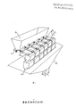
- Figure 1 is a schematic perspective view of the present invention
- Figure 2 is a schematic view of the apparatus of the present invention.
- FIG. 3 is a diagram showing the composition of the control system of the present invention.
- the quantitative granulating device of the present invention comprises a control system, a feeder 2, a conveyor 3, a camera 4, a memory hopper 5 and a hopper 6, wherein the feeder 2, the conveyor 3, the camera 4 and the memory hopper 5 are both Electrically coupled to the control system; the control system includes an image processor 7, a combined computing processor 8 and a PLC 9, as shown in Figures 2 and 3.
- the conveyor 3 is two or more, adopting stepping or vibrating driving, the feeder 2 is located above the conveyor 3, and at least one layer of the memory bucket 5 is disposed under the conveyor 3, each conveyor 3
- the discharge ends are respectively opposite to the inlet port of a top memory bucket 5 located below, and each of the memory tanks 5 of the top layer and the middle layer respectively has two side discharge ports, one side discharge port and the next layer memory
- the feed port of the bucket 5 is opposite, the other side discharge port is opposite to the feed port of the hopper 6, and the bottom memory bucket 5 is provided with a discharge port corresponding to the inlet of the hopper 6.
- the feeder 2 is connected to a silo 1 for dispensing the feed to the conveyor 3. After the conveyor 3 discharges the material, the control system outputs an instruction to feed the feeder 2 to the conveyor 3.
- the feeder 2 is generally a vibrating feeder connected to the silo 1.
- the vibrating feeder is provided with a supply port and is electrically connected with the control system, the amplitude, vibration frequency and supply port of the vibrating feeder The opening and closing is controlled by the control system.
- Belt or vibrating silos, spirals, etc. can also be used depending on the material characteristics.
- the conveyor 3 is provided with 4 to 40 units as needed, and each conveyor 3 has a corresponding number in the control system.
- the conveyors 3 can be arranged in a circular shape, a straight line shape or a polygonal shape.
- the conveyor 3 can travel a predetermined distance each time, and the driving device can be a stepping motor, a servo motor, an alternating current motor, a direct current motor, a cylinder or a hydraulic cylinder.
- the driving device can be a stepping motor, a servo motor, an alternating current motor, a direct current motor, a cylinder or a hydraulic cylinder.
- a height adjustment baffle is provided above the conveyor 3 so that overlapping materials cannot pass.
- the conveyor 3 is also equipped with a vibrating device that prevents material from overlapping by vibration.
- the conveyor 3 has a vibrator.
- the conveyors 3 can be arranged in a circular, linear shape.
- the conveyor 3 is driven by a vibrator, its vibration amplitude, vibration intensity, and vibration time can be set by the control system.
- the camera 4 is composed of a lens, a CCD photoelectric converter and a body, which is responsible for taking an image of the material on the conveyor 3 and transferring it to the image processor 7. For a clear camera effect, configure the appropriate lighting and install it in the right place on the device.
- At least one layer of the memory bucket 5 is disposed below the conveyor 3, and the discharge end of each conveyor 3 is respectively opposite to a top memory bucket inlet located below the conveyor 3
- the top memory bucket receives the material discharged from the conveyor, and after receiving the discharge instruction of the control system, discharges the material in the bucket to the next layer of the storage bucket 5 or the collector 6.
- the memory buckets 5 are arranged in layers, generally 1 to 5 layers, and the materials are discharged by the conveyor 3 or the upper memory bucket and discharged to the next layer of the memory bucket or the collector 6. After the combination calculation, the selected memory bucket 5 is directly discharged to the collector 6, and after the lower memory bucket is emptied, the upper memory bucket or the conveyor discharge is replenished, and the cycle is repeated.
- Each of the top and middle layers has two side discharge ports, one side discharge port is opposite to the feed port of the next layer of the memory bucket, and the other side discharge port is connected to the inlet of the collector.
- the bottom memory bucket is provided with a discharge port corresponding to the inlet of the hopper.
- the memory bucket outlet door can be spring-loaded or spring-free.
- the discharge port door can be driven by a cylinder, a stepping motor, or a servo motor.
- the hopper 6 may be a hopper or a collecting belt or other collecting device, and the material discharged by the conveyor 3 is discharged through the hopper 6 into a subsequent packaging machine or other equipment.
- the image processor 7 is composed of an image processing circuit and an image recognition unit.
- the image processing circuit is divided into an analog signal processor, an AD converter, and a digital signal processor.
- the image data processed by the image processing circuit is sent to the image recognition unit, and the image recognition unit processes the number of particles of each batch of material on the conveyor and transmits it to the combination calculation processor 8.
- the image recognition unit has material property memory function, dynamic compensation function, noise filtering function and other necessary functions.
- the combined computing processor 8 includes a memory and a combined computing unit.
- the memory stores the grain number data of each of the conveyor 3 and the memory bucket 5.
- the number of material on the conveyor 3 from the image recognition unit is stored in the corresponding memory.
- the grain number data stored in the memory is also transferred to the corresponding memory bucket 5 of the next layer, and so on.
- the combination calculation unit performs a combined calculation on each of the memory buckets 5 and the conveyors 3 having a known number of particles, and in the combination result of C n 1 + C n 2 + C n 3 + * ⁇ + C n n Set the target number of particles to compare and select the combination that is closest to the set value and meets the deviation criteria.
- PLC9 It is the core component of the control system, and controls the actions of the feeder 2, the camera 4, the conveyor 3, the memory bucket 5, and the collector 6, so that the entire system is linked.
- the method for realizing the quantitative particles comprises: counting the materials on the conveyor 3 for transferring the materials, and conveying the materials to the corresponding memory bucket 5, and the number of the materials corresponds to the memory bucket 5; The number of pieces of the memory bucket 5 and the material of the conveyor 3 are combined, or the memory bucket 5 of the known number of particles is combined and calculated, compared with the predetermined target number of particles, and selected within the tolerance range and closest to The combination of the target number of particles and the selected material in the memory bucket 5 and/or the conveyor 3 is discharged.
- the material in the stationary state on the conveyor 3 is imaged, and the number of particles in the state is counted instantaneously by the image recognition technology, and then the material is discharged to the memory bucket 5 according to the instruction of the control system.
- several times of imaging can be performed, and then filtered and averaged using a known mathematical model.
- the conveyor 3 travels forward according to the command of the control system and then stops.
- the feeder 2 feeds the conveyor 3 to the next process of image capturing, image recognition, and counting. It is also possible to discharge the lower memory bucket several times and accumulate several particles.
- the material on the conveyor 3 is discharged into the memory bucket according to the instruction, and the continuous image is taken when the material is in the process of falling, and the number of the material in the state is counted by the image recognition technology. Stop after setting the time or reaching the set number of particles.
- the material on the conveyor 3 is again discharged into the memory bucket 5 according to the instruction, and proceeds to the next step of imaging, image recognition, and counting.
- the upper feeder 2 is a vibrating feeder, and six conveyors 3 are provided, and each conveyor 3 is provided with upper and lower two-layer memory buckets 5, each layer is provided. There are 6 memory buckets 5, a total of 12 memory buckets 5.
- Six conveyors 3 are arranged in a straight line, using two array CCD cameras 4, each camera 4 corresponding to three conveyors 3. Each conveyor 3 and each memory bin 5 have a corresponding number in the control system.
- the vibrating feeder When there is no material on the conveyor 3, the vibrating feeder is commanded by the control system to open the supply port, and at the same time the conveyor 3 travels a certain distance according to the setting, and the vibrating feeder disperses the material to the conveyor 3.
- the camera 4 is mounted at a suitable position above the conveyor 3 and is provided with appropriate illumination to perform at least one recording of the material on the conveyor 3 in a stationary state while transmitting the obtained image data to the image processor 7.
- the image processor 7 processes the image data and analyzes the number of particles on each conveyor 3.
- the control system issues an instruction to the stepping drive device, and the conveyor 3 continues to advance a set distance, so that the material on the conveyor 3 is discharged into the lower memory bucket 5, and the number of the material is stored to The memory bucket 5 corresponds to a memory. If the lower layer memory bucket 5 is empty, the control system issues a discharge command to the upper layer memory bucket 5, and the upper layer memory bucket 5 opens the side discharge opening corresponding to the inlet of the lower layer memory bucket 5, and discharges the material in the memory bucket 5 to The lower layer memory bucket 5, at this time, the number of material particles stored in the memory corresponding to the upper layer memory bucket 5 is transferred and stored in the corresponding memory of the lower layer memory bucket 5.
- the combined calculation processor 8 pre-sets the target number of particles and the tolerance, and after reading the number of particles of each memory bucket 5 in the memory, the number of particles is calculated for all the combinations according to the principle of arrangement and combination, and the target number of particles and the allowable number The deviation is compared, and the combination of the memory buckets 5 within the tolerance range and closest to the target number of particles is selected.
- the control system opens the discharge port of the selected memory hopper 5 according to the memory hopper combination information obtained by the combination calculation processor 8, and discharges the materials therein into the hopper 6.
- the entire feeding, counting, combined calculation, and discharge processes are reciprocated under the control of the control system.
- the discharge action of the upper layer memory bucket and the upper layer memory bucket of the upper layer memory bucket may be one discharge or several discharges.
- the conveyor is connected to the control system to discharge the material to the memory bucket.
- the line CCD camera performs continuous imaging, and the obtained image data is transmitted to the image recognition unit. The number of particles is analyzed and stored in the memory of the corresponding memory bucket.
- the CCD camera described above can also be replaced with a CMOS camera.
- the quantitative granulating device of the present invention comprises a control system, a feeder 2, a conveyor 3, a camera 4, a memory hopper 5 and a hopper 6, wherein the feeder 2, the conveyor 3, the camera 4 and the memory hopper 5 are both Electrically coupled to the control system; the control system includes an image processor 7, a combined computing processor 8 and a PLC 9, as shown in Figures 2 and 3.
- the conveyor 3 is two or more, adopting stepping or vibrating driving, the feeder 2 is located above the conveyor 3, and at least one layer of the memory bucket 5 is disposed under the conveyor 3, each conveyor 3
- the discharge ends are respectively opposite to the inlet port of a top memory bucket 5 located below, and each of the memory tanks 5 of the top layer and the middle layer respectively has two side discharge ports, one side discharge port and the next layer memory
- the feed port of the bucket 5 is opposite, the other side discharge port is opposite to the feed port of the hopper 6, and the bottom memory bucket 5 is provided with a discharge port corresponding to the inlet of the hopper 6.
- the feeder 2 is connected to a silo 1 for dispensing the feed to the conveyor 3. After the conveyor 3 discharges the material, the control system outputs an instruction to feed the feeder 2 to the conveyor 3.
- the feeder 2 is generally a vibrating feeder connected to the silo 1.
- the vibrating feeder is provided with a supply port and is electrically connected with the control system, the amplitude, vibration frequency and supply port of the vibrating feeder The opening and closing is controlled by the control system.
- Belt or vibrating silos, spirals, etc. can also be used depending on the material characteristics.
- the conveyor 3 is provided with 4 to 40 units as needed, and each conveyor 3 has a corresponding number in the control system.
- the conveyors 3 can be arranged in a circular shape, a straight line shape or a polygonal shape.
- the conveyor 3 can travel a predetermined distance each time, and the driving device can be a stepping motor, a servo motor, an alternating current motor, a direct current motor, a cylinder or a hydraulic cylinder.
- the driving device can be a stepping motor, a servo motor, an alternating current motor, a direct current motor, a cylinder or a hydraulic cylinder.
- a height adjusting baffle is arranged above the conveyor 3, so that the overlapping materials cannot pass.
- the conveyor 3 is also equipped with a vibrating device that prevents material from overlapping by vibration.
- the conveyor 3 has a vibrator.
- the conveyors 3 can be arranged in a circular, linear shape.
- the conveyor 3 is driven by a vibrator, its vibration amplitude, vibration intensity, and vibration time can be set by the control system.
- the camera 4 is composed of a lens, a CCD photoelectric converter and a body, which is responsible for taking an image of the material on the conveyor 3 and transferring it to the image processor 7. For a clear camera effect, configure the appropriate lighting and install it in the right place on the device.
- At least one layer of the memory bucket 5 is disposed below the conveyor 3, and the discharge end of each conveyor 3 is respectively opposite to a top memory bucket inlet located below the conveyor 3
- the top memory bucket receives the material discharged from the conveyor, and after receiving the discharge instruction of the control system, discharges the material in the bucket to the next layer of the storage bucket 5 or the collector 6.
- the memory buckets 5 are arranged in layers, generally 1 to 5 layers, and the materials are discharged by the conveyor 3 or the upper memory bucket and discharged to the next layer of the memory bucket or the collector 6. After the combination calculation, the selected memory bucket 5 is directly discharged to the collector 6, and after the lower memory bucket is emptied, the upper memory bucket or the conveyor discharge is replenished, and the cycle is repeated.
- Each of the top and middle layers has two side discharge ports, one side discharge port is opposite to the feed port of the next layer of the memory bucket, and the other side discharge port is connected to the inlet of the collector.
- the bottom memory bucket is provided with a discharge port corresponding to the inlet of the hopper.
- the memory bucket outlet door can be spring-loaded or spring-free.
- the discharge port door can be driven by a cylinder, a stepping motor, or a servo motor.
- the hopper 6 may be a hopper or a collecting belt or other collecting device, and the material discharged by the conveyor 3 is discharged through the hopper 6 into a subsequent packaging machine or other equipment.
- the image processor 7 is composed of an image processing circuit and an image recognition unit.
- the image processing circuit is divided into an analog signal processor, an AD converter, and a digital signal processor.
- the image data processed by the image processing circuit is transmitted to the image recognition unit, and the image recognition unit processes the number of the batches of the materials on the conveyor and transmits them to the combination calculation processor 8 .
- the image recognition unit has material property memory function, dynamic compensation function, noise filtering function and other necessary functions.
- the combined computing processor 8 includes a memory and a combined computing unit.
- the memory stores the grain number data of each of the conveyor 3 and the memory bucket 5.
- the number of material on the conveyor 3 from the image recognition unit is stored in the corresponding memory.
- the grain number data stored in the memory is also transferred to the corresponding memory bucket 5 of the next layer, and so on.
- the combination calculation unit performs a combined calculation on each of the memory buckets 5 and the conveyors 3 having a known number of particles, and in the combination result of C n 1 + C n 2 + C n 3 + ⁇ + C n n Set the target number of particles to compare and select the combination that is closest to the set value and meets the deviation criteria.
- PLC9 It is the core component of the control system, and controls the actions of the feeder 2, the camera 4, the conveyor 3, the memory bucket 5, and the collector 6, so that the entire system is linked.
- the method for realizing the quantitative particles comprises: counting the materials on the conveyor 3 for transferring the materials, and conveying the materials to the corresponding memory bucket 5, and the number of the materials corresponds to the memory bucket 5; The number of pieces of the memory bucket 5 and the material of the conveyor 3 are combined, or the memory bucket 5 of the known number of particles is combined and calculated, compared with the predetermined target number of particles, and selected within the tolerance range and closest to The combination of the target number of particles and the selected material in the memory bucket 5 and/or the conveyor 3 is discharged.
- the material in the stationary state on the conveyor 3 is imaged, and the number of particles in the state is counted instantaneously by the image recognition technology, and then the material is discharged to the memory bucket 5 according to the instruction of the control system.
- several times of imaging can be performed, and then filtered and averaged using a known mathematical model.
- the conveyor 3 travels forward according to the command of the control system and then stops.
- the feeder 2 feeds the conveyor 3 to the next process of image capturing, image recognition, and counting. It is also possible to discharge the lower memory bucket several times and accumulate several particles.
- the material on the conveyor 3 is discharged into the memory bucket according to the instruction, and the continuous image is taken when the material is in the process of falling, and the number of the material in the state is counted by the image recognition technology. Stop after setting the time or reaching the set number of particles.
- the material on the conveyor 3 is again discharged into the memory bucket 5 according to the instruction, and proceeds to the next step of imaging, image recognition, and counting.
- the upper feeder 2 is a vibrating feeder, and six conveyors 3 are provided, and each conveyor 3 is provided with upper and lower two-layer memory buckets 5, each layer is provided. There are 6 memory buckets 5, a total of 12 memory buckets 5.
- Six conveyors 3 are arranged in a straight line, using two array CCD cameras 4, each camera 4 corresponding to three conveyors 3. Each conveyor 3 and each memory bin 5 have a corresponding number in the control system.
- the vibrating feeder When there is no material on the conveyor 3, the vibrating feeder is commanded by the control system to open the supply port, and at the same time the conveyor 3 travels a certain distance according to the setting, and the vibrating feeder disperses the material to the conveyor 3.
- the camera 4 is mounted at a suitable position above the conveyor 3 and is provided with appropriate illumination to perform at least one recording of the material on the conveyor 3 in a stationary state while transmitting the obtained image data to the image processor 7.
- the image processor 7 processes the image data and analyzes the number of particles on each conveyor 3.
- the control system issues an instruction to the stepping drive device, and the conveyor 3 continues to advance a set distance, so that the material on the conveyor 3 is discharged into the lower memory bucket 5, and the number of the material is stored to The memory bucket 5 corresponds to a memory. If the lower layer memory bucket 5 is empty, the control system issues a discharge command to the upper layer memory bucket 5, and the upper layer memory bucket 5 opens the side discharge opening corresponding to the inlet of the lower layer memory bucket 5, and discharges the material in the memory bucket 5 to The lower layer memory bucket 5, at this time, the number of material particles stored in the memory corresponding to the upper layer memory bucket 5 is transferred and stored in the corresponding memory of the lower layer memory bucket 5.
- the combined calculation processor 8 pre-sets the target number of particles and the tolerance, and after reading the number of particles of each memory bucket 5 in the memory, the number of particles is calculated for all the combinations according to the principle of arrangement and combination, and the target number of particles and the allowable number The deviation is compared, and the combination of the memory buckets 5 within the tolerance range and closest to the target number of particles is selected.
- the control system opens the discharge port of the selected memory hopper 5 according to the memory hopper combination information obtained by the combination calculation processor 8, and discharges the materials therein into the hopper 6.
- the entire feeding, counting, combined calculation, and discharge processes are reciprocated under the control of the control system.
- the discharge action of the upper layer memory bucket and the upper layer memory bucket of the upper layer memory bucket may be one discharge or several discharges.
- the conveyor is connected to the control system to discharge the material to the memory bucket.
- the line CCD camera performs continuous imaging, and the obtained image data is transmitted to the image recognition unit. The number of particles is analyzed and stored in the memory of the corresponding memory bucket.
- the CCD camera described above can also be replaced with a CMOS camera.
- the accuracy of the simple weighing equipment is 2%, the speed is 320,000/min; the accuracy of the simple linear array CCD counting equipment is 0.1%, and the speed of the 1 joint is about 1000/time, 5 times/min. That is, 5000 capsules/min. If 6 joints are used, it is 30,000 capsules/min.
- the quantitative granulating device of the invention has higher precision than the weighing method and the volume method, and the precision of the batch granule is 0.1%, and the combination usually selects 3 to 5 memory hoppers, so the final quantitative granule precision is 0.3. % ⁇ 0.5%, and the speed of discharge is much higher than the existing numbering method, the discharge speed can reach 30-60 times/min, and the number of grains can reach 240,000-480,000/min.
Landscapes
- Engineering & Computer Science (AREA)
- Mechanical Engineering (AREA)
- Quality & Reliability (AREA)
- Physics & Mathematics (AREA)
- General Physics & Mathematics (AREA)
- Theoretical Computer Science (AREA)
- Filling Or Emptying Of Bunkers, Hoppers, And Tanks (AREA)
- Control Of Conveyors (AREA)
- Sorting Of Articles (AREA)
Abstract
L'invention concerne un procédé et un dispositif pour le comptage quantitatif de granules. Le dispositif comprend un système de commande, un chargeur, un transporteur, une caméra, un compartiment de mémoire et une trancheuse, le système de commande comprenant un processeur d'images, un processeur de calcul combiné et un PLC; le chargeur alimente le transporteur de manière dispersée, au moins un compartiment de mémoire est disposé en couches sous le transporteur, la caméra et le processeur d'images acquièrent des données d'images pour le matériau disposé sur le transporteur et analysent et comptent des granules, et le matériau est transporté vers le compartiment de mémoire correspondant, le nombre de granules du matériau correspondant au compartiment de mémoire; le processeur de calcul combiné combine et calcule la quantité de matériau dans tous les compartiments de mémoire et compare celle-ci à un nombre de granules cible prédéterminé, sélectionne une combinaison de compartiments de mémoire qui est la plus proche du nombre de granules cible et qui se situe dans une plage de déviation autorisée, et retire le matériau des compartiments de mémoire sélectionnés. La présente invention combine la technologie de comptage de granules CCD par lots dans laquelle le nombre de granules ne peut pas être contrôlé à l'aide de la technologie de calcul combinée, et la précision et la vitesse de comptage quantitatif de granules peuvent par conséquent être considérablement améliorées.
Applications Claiming Priority (2)
| Application Number | Priority Date | Filing Date | Title |
|---|---|---|---|
| CN201110214864.XA CN102390578B (zh) | 2011-07-29 | 2011-07-29 | 定量数粒的实现方法 |
| CN201110214864.X | 2011-07-29 |
Publications (1)
| Publication Number | Publication Date |
|---|---|
| WO2013016881A1 true WO2013016881A1 (fr) | 2013-02-07 |
Family
ID=45858003
Family Applications (1)
| Application Number | Title | Priority Date | Filing Date |
|---|---|---|---|
| PCT/CN2011/078523 Ceased WO2013016881A1 (fr) | 2011-07-29 | 2011-08-17 | Procédé et dispositif pour le comptage quantitatif de granules |
Country Status (2)
| Country | Link |
|---|---|
| CN (1) | CN102390578B (fr) |
| WO (1) | WO2013016881A1 (fr) |
Cited By (5)
| Publication number | Priority date | Publication date | Assignee | Title |
|---|---|---|---|---|
| CN109204969A (zh) * | 2018-10-11 | 2019-01-15 | 江苏环实科技有限公司 | 牙线数量检测装置及其控制方法 |
| CN111762350A (zh) * | 2019-04-01 | 2020-10-13 | 上海大和衡器有限公司 | 一种多头混料秤 |
| CN114084439A (zh) * | 2022-01-24 | 2022-02-25 | 成都飞机工业(集团)有限责任公司 | 一种小标件分拣、报废、更换、回收的装置及方法 |
| CN114123709A (zh) * | 2021-12-27 | 2022-03-01 | 楚天科技股份有限公司 | 一种直线电机装置及数粒机 |
| CN114626497A (zh) * | 2022-03-08 | 2022-06-14 | 中国兵器装备集团自动化研究所有限公司 | 一种颗粒发射药多通道协作计量方法、系统及装置 |
Families Citing this family (12)
| Publication number | Priority date | Publication date | Assignee | Title |
|---|---|---|---|---|
| CN102700739B (zh) * | 2012-06-20 | 2013-11-06 | 上海大和衡器有限公司 | 一种按粒数分装的定量包装秤及其定量称重方法 |
| CN103569628A (zh) * | 2012-07-18 | 2014-02-12 | 上海朝洋机电设备有限公司 | 测距数粒和定距移动的定量数粒方法及装置 |
| CN103895904B (zh) * | 2014-03-21 | 2016-04-06 | 达尔嘉(广州)标识设备有限公司 | 一种片状物品的分配方法及分配装置 |
| CN104260944B (zh) * | 2014-08-11 | 2016-04-06 | 深圳市联星服装辅料有限公司 | 光电式纽扣计数机 |
| CN104554934B (zh) * | 2014-12-26 | 2017-09-29 | 达尔嘉(广州)标识设备有限公司 | 独立控制通道输出物品的定量分堆及计数的方法及装置 |
| CN106169093B (zh) * | 2016-06-28 | 2019-02-19 | 上海卫岚电子科技有限公司 | 基于机器视觉的运动物体的高速计数装置与方法 |
| CN106934449B (zh) * | 2017-04-27 | 2023-04-18 | 江苏瑞奇海力科技有限公司 | 基于cis扫描的颗粒高速连续计数计量系统 |
| CN110239797B (zh) * | 2019-04-22 | 2021-11-16 | 达尔嘉(广州)标识设备有限公司 | 一种离散物品的计数方法 |
| CN110979858B (zh) * | 2019-12-16 | 2024-02-27 | 广州珐玛珈智能设备股份有限公司 | 一种颗粒物料的包装数粒机及数粒方法 |
| CN111689006A (zh) * | 2020-06-03 | 2020-09-22 | 合肥安杰特光电科技有限公司 | 包装机的计数装置 |
| CN116823762A (zh) * | 2023-06-25 | 2023-09-29 | 江苏泗阳协力轻工机械有限公司 | 一种计数分离设备 |
| CN116767609A (zh) * | 2023-06-25 | 2023-09-19 | 江苏泗阳协力轻工机械有限公司 | 一种包装生产线 |
Citations (5)
| Publication number | Priority date | Publication date | Assignee | Title |
|---|---|---|---|---|
| FR2613957A1 (fr) * | 1987-04-17 | 1988-10-21 | Panavi Sa | Dispositif pour compter des articles en mouvement et pour les separer en groupes numeriquement identiques |
| EP0763470A1 (fr) * | 1995-09-18 | 1997-03-19 | Pierre Robert | Machine et procédé de tri et de regroupement d'articles individuels en vue de leur conditionnement par quantité prédéterminée |
| CN2513910Y (zh) * | 2000-11-17 | 2002-10-02 | 林胜信 | 自动计数计量包装机 |
| CN101486391A (zh) * | 2008-01-18 | 2009-07-22 | 北京光电技术研究所 | 金属棒材自动分离方法及装置 |
| CN201770034U (zh) * | 2010-08-06 | 2011-03-23 | 鼎贞(厦门)实业有限公司 | 多轨道光电式数粒机构 |
Family Cites Families (10)
| Publication number | Priority date | Publication date | Assignee | Title |
|---|---|---|---|---|
| WO1992005410A1 (fr) * | 1990-09-17 | 1992-04-02 | Anritsu Corporation | Systeme de mesure servant a mesurer facilement avec un grande precision une large gamme de produits, y compris des substances visqueuses |
| US5463839A (en) * | 1994-08-04 | 1995-11-07 | The Lakso Company | Apparatus for packaging a predetermined quantity of objects and a counting device therefor |
| WO1997014020A1 (fr) * | 1995-10-12 | 1997-04-17 | Yamato Scale Company Limited | Procede de pesage combinatoire et balance combinatoire |
| JP3537772B2 (ja) * | 2001-01-19 | 2004-06-14 | 株式会社イシダ | 組合せ計量装置 |
| JP2003177056A (ja) * | 2001-12-13 | 2003-06-27 | Ishida Co Ltd | 組合せ計量装置 |
| ITBO20020313A1 (it) * | 2002-05-21 | 2003-11-21 | Ima Spa | Unita per il riempimento di contenitori con prodotti , in particolarearticoli farmaceutici |
| CN2734627Y (zh) * | 2004-09-28 | 2005-10-19 | 珐玛珈(广州)包装设备有限公司 | 一种新型数粒机 |
| CN201086853Y (zh) * | 2007-01-19 | 2008-07-16 | 珐玛珈(广州)包装设备有限公司 | 一种片状大型物料数粒机 |
| CN201142086Y (zh) * | 2008-01-11 | 2008-10-29 | 江苏沙钢集团有限公司 | 用于棒材在线计数的拍摄装置 |
| CN202186541U (zh) * | 2011-07-29 | 2012-04-11 | 上海朝洋机电设备有限公司 | 定量数粒装置 |
-
2011
- 2011-07-29 CN CN201110214864.XA patent/CN102390578B/zh not_active Expired - Fee Related
- 2011-08-17 WO PCT/CN2011/078523 patent/WO2013016881A1/fr not_active Ceased
Patent Citations (5)
| Publication number | Priority date | Publication date | Assignee | Title |
|---|---|---|---|---|
| FR2613957A1 (fr) * | 1987-04-17 | 1988-10-21 | Panavi Sa | Dispositif pour compter des articles en mouvement et pour les separer en groupes numeriquement identiques |
| EP0763470A1 (fr) * | 1995-09-18 | 1997-03-19 | Pierre Robert | Machine et procédé de tri et de regroupement d'articles individuels en vue de leur conditionnement par quantité prédéterminée |
| CN2513910Y (zh) * | 2000-11-17 | 2002-10-02 | 林胜信 | 自动计数计量包装机 |
| CN101486391A (zh) * | 2008-01-18 | 2009-07-22 | 北京光电技术研究所 | 金属棒材自动分离方法及装置 |
| CN201770034U (zh) * | 2010-08-06 | 2011-03-23 | 鼎贞(厦门)实业有限公司 | 多轨道光电式数粒机构 |
Cited By (6)
| Publication number | Priority date | Publication date | Assignee | Title |
|---|---|---|---|---|
| CN109204969A (zh) * | 2018-10-11 | 2019-01-15 | 江苏环实科技有限公司 | 牙线数量检测装置及其控制方法 |
| CN111762350A (zh) * | 2019-04-01 | 2020-10-13 | 上海大和衡器有限公司 | 一种多头混料秤 |
| CN114123709A (zh) * | 2021-12-27 | 2022-03-01 | 楚天科技股份有限公司 | 一种直线电机装置及数粒机 |
| CN114084439A (zh) * | 2022-01-24 | 2022-02-25 | 成都飞机工业(集团)有限责任公司 | 一种小标件分拣、报废、更换、回收的装置及方法 |
| CN114084439B (zh) * | 2022-01-24 | 2022-05-06 | 成都飞机工业(集团)有限责任公司 | 一种小标件分拣、报废、更换、回收的装置及方法 |
| CN114626497A (zh) * | 2022-03-08 | 2022-06-14 | 中国兵器装备集团自动化研究所有限公司 | 一种颗粒发射药多通道协作计量方法、系统及装置 |
Also Published As
| Publication number | Publication date |
|---|---|
| CN102390578A (zh) | 2012-03-28 |
| CN102390578B (zh) | 2014-05-28 |
Similar Documents
| Publication | Publication Date | Title |
|---|---|---|
| WO2013016881A1 (fr) | Procédé et dispositif pour le comptage quantitatif de granules | |
| US5319160A (en) | Apparatus for collecting an article | |
| CN109592116B (zh) | 一种混合坚果包装系统及其控制方法 | |
| CN103895904B (zh) | 一种片状物品的分配方法及分配装置 | |
| WO2015139545A1 (fr) | Procédé et dispositif pour diviser de façon quantitative des articles par quantités et compter des articles | |
| CN107963246A (zh) | 一种基于ccd的高速视觉计数机 | |
| CN101636319A (zh) | 连接装置和使用该装置的计量装置、包装装置以及计量包装系统 | |
| CN212710090U (zh) | 计数称重筛选机 | |
| AU2008233899A1 (en) | Link apparatus, weighing apparatus using link apparatus, packaging apparatus using link apparatus and weighing and packaging system using link apparatus | |
| EP0642002B1 (fr) | Systèmes et méthodes combinatoires de mesure | |
| CN108394702B (zh) | 槟榔装盘机构 | |
| CN207932042U (zh) | 一种基于ccd的高速视觉计数机 | |
| CN102640172B (zh) | 用于对作为散装物料供给的物品计数的设备 | |
| CN202574656U (zh) | 即时数粒补偿的数粒称重一体机 | |
| CN1606973A (zh) | 一种将固体药剂馈送给填充胶囊机器的传送线的设备 | |
| CN219182411U (zh) | 一种吊轨式精准加药饲喂机器人 | |
| US20230152144A1 (en) | Weighing and transporting device and method for transporting and detecting mass flow rates of bulk materials | |
| CN214356788U (zh) | 一种加料机构及槟榔包装生产线 | |
| JP6289145B2 (ja) | 重量測定装置 | |
| CN105416718A (zh) | 一种全自动在线高速计数机 | |
| CN207932490U (zh) | 一种振动输送装置 | |
| CN205131800U (zh) | 一种全自动在线高速计数机 | |
| JPH06255601A (ja) | 定量容積充填装置 | |
| CN205892007U (zh) | 一种自动点数机及自动点数系统 | |
| CN117104568A (zh) | 一种鱼饲料分包装置 |
Legal Events
| Date | Code | Title | Description |
|---|---|---|---|
| 121 | Ep: the epo has been informed by wipo that ep was designated in this application |
Ref document number: 11870235 Country of ref document: EP Kind code of ref document: A1 |
|
| NENP | Non-entry into the national phase |
Ref country code: DE |
|
| 122 | Ep: pct application non-entry in european phase |
Ref document number: 11870235 Country of ref document: EP Kind code of ref document: A1 |