WO2013018131A1 - 燃料供給装置 - Google Patents
燃料供給装置 Download PDFInfo
- Publication number
- WO2013018131A1 WO2013018131A1 PCT/JP2011/004362 JP2011004362W WO2013018131A1 WO 2013018131 A1 WO2013018131 A1 WO 2013018131A1 JP 2011004362 W JP2011004362 W JP 2011004362W WO 2013018131 A1 WO2013018131 A1 WO 2013018131A1
- Authority
- WO
- WIPO (PCT)
- Prior art keywords
- fuel
- pressure
- switching
- valve
- state
- Prior art date
- Legal status (The legal status is an assumption and is not a legal conclusion. Google has not performed a legal analysis and makes no representation as to the accuracy of the status listed.)
- Ceased
Links
Images








Classifications
-
- F—MECHANICAL ENGINEERING; LIGHTING; HEATING; WEAPONS; BLASTING
- F02—COMBUSTION ENGINES; HOT-GAS OR COMBUSTION-PRODUCT ENGINE PLANTS
- F02D—CONTROLLING COMBUSTION ENGINES
- F02D41/00—Electrical control of supply of combustible mixture or its constituents
- F02D41/30—Controlling fuel injection
- F02D41/38—Controlling fuel injection of the high pressure type
- F02D41/3809—Common rail control systems
- F02D41/3836—Controlling the fuel pressure
- F02D41/3845—Controlling the fuel pressure by controlling the flow into the common rail, e.g. the amount of fuel pumped
- F02D41/3854—Controlling the fuel pressure by controlling the flow into the common rail, e.g. the amount of fuel pumped with elements in the low pressure part, e.g. low pressure pump
-
- F—MECHANICAL ENGINEERING; LIGHTING; HEATING; WEAPONS; BLASTING
- F02—COMBUSTION ENGINES; HOT-GAS OR COMBUSTION-PRODUCT ENGINE PLANTS
- F02D—CONTROLLING COMBUSTION ENGINES
- F02D33/00—Controlling delivery of fuel or combustion-air, not otherwise provided for
- F02D33/003—Controlling the feeding of liquid fuel from storage containers to carburettors or fuel-injection apparatus ; Failure or leakage prevention; Diagnosis or detection of failure; Arrangement of sensors in the fuel system; Electric wiring; Electrostatic discharge
-
- F—MECHANICAL ENGINEERING; LIGHTING; HEATING; WEAPONS; BLASTING
- F02—COMBUSTION ENGINES; HOT-GAS OR COMBUSTION-PRODUCT ENGINE PLANTS
- F02M—SUPPLYING COMBUSTION ENGINES IN GENERAL WITH COMBUSTIBLE MIXTURES OR CONSTITUENTS THEREOF
- F02M37/00—Apparatus or systems for feeding liquid fuel from storage containers to carburettors or fuel-injection apparatus; Arrangements for purifying liquid fuel specially adapted for, or arranged on, internal-combustion engines
- F02M37/0011—Constructional details; Manufacturing or assembly of elements of fuel systems; Materials therefor
- F02M37/0023—Valves in the fuel supply and return system
- F02M37/0029—Pressure regulator in the low pressure fuel system
-
- F—MECHANICAL ENGINEERING; LIGHTING; HEATING; WEAPONS; BLASTING
- F02—COMBUSTION ENGINES; HOT-GAS OR COMBUSTION-PRODUCT ENGINE PLANTS
- F02M—SUPPLYING COMBUSTION ENGINES IN GENERAL WITH COMBUSTIBLE MIXTURES OR CONSTITUENTS THEREOF
- F02M37/00—Apparatus or systems for feeding liquid fuel from storage containers to carburettors or fuel-injection apparatus; Arrangements for purifying liquid fuel specially adapted for, or arranged on, internal-combustion engines
- F02M37/0047—Layout or arrangement of systems for feeding fuel
- F02M37/0052—Details on the fuel return circuit; Arrangement of pressure regulators
- F02M37/0058—Returnless fuel systems, i.e. the fuel return lines are not entering the fuel tank
Definitions
- the present invention relates to a fuel supply device that regulates fuel stored in a fuel tank and supplies the fuel to a fuel consumption unit.
- a fuel supply device for an internal combustion engine mounted on a vehicle has a pressure control for adjusting the fuel supply pressure to the fuel consumption unit when the fuel stored in the fuel tank is supplied to the fuel consumption unit by a fuel pump. Equipment.
- This pressure control device regulates the fuel supply pressure from the fuel pump that pumps up the fuel in the fuel tank to the injector that constitutes the fuel consumption unit.
- Such a pressure control device is generally provided with a diaphragm having a housing divided into two chambers and a pressure regulating valve body at the center. On one surface side of this diaphragm, the pressure regulating valve body is displaced in the valve opening direction and the valve closing direction by using the displacement of the diaphragm central portion in accordance with the fuel pressure in the pressure regulating chamber, while being installed on the other surface side of the diaphragm. The displacement of the diaphragm is suppressed by a compression coil spring. Thereby, the valve opening state of the pressure regulating valve body is maintained so that the fuel pressure in the pressure regulating chamber reaches the set pressure. Further, such a pressure control device is often arranged in a fuel tank together with a fuel pump.
- a pressure control device there is a diaphragm partitioning the inside of the housing, a fuel introduction port for introducing pressurized fuel from a fuel pump, and a discharge port for discharging excess fuel, which are located on one surface side of the diaphragm.
- the fuel supply device described in Patent Document 1 includes a variable fuel pressure adjustment valve that constitutes such a pressure control device, thereby switching the set load of the spring in two stages depending on whether or not the back pressure fluid is supplied.
- the set value of the fuel pressure to be regulated can be switched between low pressure and high pressure.
- control unit that controls the fuel pressure was not intended to take into account the time required to switch the fuel pressure. For this reason, fuel may be injected during the switching of the fuel pressure, and the target fuel pressure and the actual fuel pressure may deviate. As a result, there is a problem that the fuel injection amount to the cylinder is not appropriate, and the air-fuel ratio may deviate from the target air-fuel ratio.
- the fuel supply device disclosed in Patent Document 2 includes two variable fuel pressure adjusting valves, an electromagnetic valve that switches the state of these variable fuel pressure adjusting valves, and an ECU that controls the electromagnetic valves.
- the fuel supply device described in Patent Document 2 requires two variable fuel pressure regulating valves to switch the fuel pressure, so that there is a problem of downsizing.
- the ECU sets the fuel injection amount for the cylinder in accordance with the fuel pressure, thereby bringing the actual air-fuel ratio closer to the target air-fuel ratio. Further, when changing the fuel pressure, a change in the actual fuel pressure is predicted based on the engine speed.
- the response time of the electromagnetic valve changes according to the running state of the vehicle, and the time from when the fuel pressure switching instruction is issued by the ECU to when the fuel pressure actually starts to change and the fluctuation of the fuel pressure converge.
- the ECU has not sufficiently optimized the timing for issuing the switching instruction and the fuel injection timing. Therefore, there is a possibility that the fuel is injected in a state where the actual fuel pressure is not equal to the target fuel pressure, and the actual fuel injection amount deviates from the desired fuel injection amount. For this reason, there has been a problem that the accuracy of the fuel injection control is lowered and the fuel efficiency cannot be improved.
- the present invention has been made to solve such problems, and in a fuel supply device having a variable fuel pressure adjusting valve, the timing for instructing the switching of fuel pressure and the timing of fuel injection are optimized to reduce the fuel pressure.
- An object of the present invention is to provide a fuel supply device capable of improving fuel consumption by suppressing the actual fuel injection amount from deviating from a desired fuel injection amount even when the fuel injection is changed.
- a fuel supply device is a fuel supply device that regulates fuel and supplies the fuel to a fuel consuming unit, and at least a high pressure supply state in which the fuel pressure of the fuel is high and a low pressure in which the fuel pressure is low
- a variable fuel pressure regulating valve that can be in any one of a supply state, and a state of the variable fuel pressure regulating valve between the high-pressure supply state and the low-pressure supply state in accordance with an electric characteristic of input electric power.
- a switching control means for controlling whether or not the power is input to at least the switching valve, and the switching control means is based on the electrical characteristics of the power input to the switching valve. The switching timing for switching the state of the switching valve is set.
- the switching control means can change the control timing for the switching valve according to the electrical characteristics input to the switching valve. Therefore, even when the switching time of the switching valve varies depending on the electrical characteristics, it is possible to reduce the influence on the fuel injection control by making the switching timing variable. For this reason, the timing at which the switching instruction is given and the fuel injection timing are optimized, and even when the fuel pressure is switched, the actual fuel injection amount can be prevented from deviating from the desired fuel injection amount. In addition, the accuracy of fuel injection control can be improved, and fuel consumption can be improved.
- the switching control means compares the electrical characteristic with a value at which switching is early when the state of the switching valve is a value at which switching is started late.
- the switching timing is set earlier.
- the switching control means suppresses the influence of electrical characteristics on the fuel pressure control by advancing the switching timing when the switching valve state starts switching late compared to when switching starts earlier. can do.
- the fuel supply device is characterized in that the value of the electrical characteristic is a magnitude of an electromotive force of an alternator that generates power by power output from an internal combustion engine.
- the switching control means can calculate the timing at which the state of the switching valve switches based on the magnitude of the electromotive force of the alternator. Therefore, it is not necessary to directly detect the fuel pressure of the fuel supplied to the fuel consumption unit, and it is not necessary to provide a sensor for detecting the fuel pressure. Therefore, it is possible to improve the accuracy of the fuel pressure switching control at a low cost.
- the fuel supply device is characterized in that the switching control means uses the electromotive force of the alternator before switching the state of the switching valve as the electrical characteristic.
- the switching control means can set the timing at which the state of the switching valve starts to switch based on the electromotive force of the alternator. Therefore, it is possible to predict the time required for the fuel pressure to reach a steady state by measuring in advance the time required for switching the state of the switching valve and the time from when the fuel pressure changes to the steady state. It becomes possible.
- the fuel supply device is a fuel supply device that regulates the fuel and supplies the fuel to the fuel consumption unit, and includes at least a high pressure supply state in which the fuel pressure of the fuel is high and a low pressure supply state in which the fuel pressure is low.
- a variable fuel pressure regulating valve that can take either state, and a switching valve that switches the state of the variable fuel pressure regulating valve between the high pressure supply state and the low pressure supply state according to the electrical characteristics of the input power Switching control means for controlling whether or not the power is input to at least the switching valve, and the switching control means switches the electric power supply on the condition that the power supply to the switching valve is switched.
- a characteristic required for switching the fuel pressure is predicted based on the detected electrical characteristic.
- the switching control means can calculate the time for switching the state of the switching valve in accordance with the electrical characteristics input to the switching valve. Therefore, even when the switching time of the switching valve varies depending on the electrical characteristics, the influence on the fuel injection control can be reduced by calculating the switching time of the switching valve. For this reason, the timing at which the switching instruction is given and the fuel injection timing are optimized, and even when the fuel pressure is switched, the actual fuel injection amount can be prevented from deviating from the desired fuel injection amount. In addition, the accuracy of fuel injection control can be improved, and fuel consumption can be improved.
- the switching control means switches the fuel pressure after switching the presence or absence of power supply to the switching valve and before the state of the switching valve starts to switch. It is characterized by predicting the required time.
- the switching control means can predict the time when the switching valve state starts to switch. Thereby, the timing at which the switching instruction is given and the fuel injection timing are optimized, and even when the fuel pressure is switched, the actual fuel injection amount can be prevented from deviating from the desired fuel injection amount.
- the fuel supply device is characterized in that the switching control means uses a current value of electric power input to the switching valve as the electrical characteristic.
- This configuration makes it possible to calculate the time required to switch the state of the switching valve even after a switching instruction is given to the switching valve.
- the fuel supply apparatus further comprises fuel injection control means for controlling timing of fuel injection in the fuel consuming unit, wherein the fuel injection control means is the fuel pressure calculated by the switching control means.
- the timing for injecting the fuel is adjusted based on the time required for the switching.
- the fuel pressure at a certain time point is predicted by calculating the time required for the fuel pressure to switch, and based on the predicted fuel pressure at that time point.
- the accuracy of the fuel injection amount can be improved.
- the fuel supply device includes a disconnection detection means for detecting whether or not a disconnection has occurred in the wiring that supplies current to the switching valve based on the magnitude of the current flowing through the wiring,
- the switching control means calculates the switching timing based on the magnitude of the current detected by the disconnection detecting means.
- the switching control means can calculate the timing at which the state of the switching valve switches based on the magnitude of the current supplied to the switching valve. Therefore, it is not necessary to directly detect the fuel pressure of the fuel supplied to the fuel consumption unit, and it is not necessary to provide a sensor for detecting the fuel pressure. Therefore, it is possible to increase the accuracy of the switching control at a low cost.
- variable fuel pressure adjusting valve is disposed between the housing having a fuel introduction port into which the fuel is introduced and a fuel discharge port through which the fuel is discharged, and the housing.
- a partition portion that forms a pressure regulating chamber that communicates with the fuel inlet, and a movable valve body that is displaced in a valve opening direction that communicates the pressure regulating chamber with the fuel discharge port according to the fuel pressure in the pressure regulating chamber.
- a pressure regulating member and a first valve seat portion that communicates with the fuel discharge port inside the pressure regulating chamber and forms a discharge hole whose opening degree changes according to the displacement of the movable valve body portion;
- a second valve seat portion that forms an operating pressure fuel introduction hole into which the fuel having an operating pressure is introduced while the opening degree changes in accordance with the displacement of the movable valve body portion inside the pressure regulating chamber,
- the pressure regulating member is provided in the housing and burns in the valve opening direction.
- the area receiving the pressure characterized in that changes in accordance with the operating pressure of the operating fuel introduction hole.
- the fuel pressure is regulated in two stages by making the area where the pressure regulating member receives the fuel pressure variable. Therefore, the fuel pressure supplied to the fuel consumption unit can be controlled in two stages without providing the variable fuel pressure adjusting valve with three chambers or providing two variable fuel pressure adjusting valves. For this reason, a fuel supply apparatus can be reduced in size.
- the timing of issuing a switching instruction and the fuel injection timing are optimized, and the actual fuel injection amount is set to a desired fuel injection even when the fuel pressure is switched. By suppressing the deviation from the amount, it is possible to provide a fuel supply device that can improve fuel efficiency.
- 1 is a schematic block configuration diagram of a fuel supply device according to a first embodiment of the present invention. It is a circuit diagram around the power supply unit according to the first embodiment of the present invention.
- the fuel supply device 8 includes a fuel tank 2 that stores fuel consumed by the engine 1, and fuel stored in the fuel tank 2.
- a fuel pumping mechanism 10 that pumps the fuel to a plurality of injectors 3 of the engine 1, a pressure regulator 20 that introduces fuel supplied from the fuel pumping mechanism 10 to the injector 3 and adjusts the fuel pressure P1 to a preset value, and a pressure regulator 20
- a switching valve 60 that controls the pressure regulator 20 so as to switch the fuel pressure P1 regulated by the pressure between the high-pressure side set pressure and the low-pressure side set pressure.
- the pressure regulator 20 constitutes a variable fuel pressure regulating valve according to the present invention.
- the engine 1 is composed of a multi-cylinder internal combustion engine mounted on a vehicle.
- an internal combustion engine is constituted by a four-cycle gasoline engine having four cylinders 5.
- each cylinder 5 comprises the fuel consumption part which concerns on this invention.
- the injector 3 is installed in each cylinder 5 of the engine 1, and an end 3 a that forms an injection hole is exposed in the intake port 7.
- the fuel pressure feeding mechanism 10 and the injector 3 are connected via the delivery pipe 4, and the fuel from the fuel pressure feeding mechanism 10 is distributed to each injector 3 via the delivery pipe 4.
- the fuel pumping mechanism 10 pumps the fuel in the fuel tank 2 from the suction port, pressurizes it and discharges it from the discharge port, and is installed on the suction port side of the fuel pump unit 11 to the fuel pump unit 11.
- a suction filter 12 that prevents foreign matter from being sucked in
- a fuel filter 13 that is installed on the discharge port side of the fuel pump unit 11 to remove foreign matters contained in the fuel discharged from the fuel pump unit 11, and an upstream side of the fuel filter 13 or
- a check valve 14 installed on the downstream side.
- the fuel pump unit 11 is controlled by an ECU (Electronic Control Unit) 51 described later to energize a fuel pump 11p having an impeller for operating the pump and a pump drive motor 11m that is a built-in DC motor that rotationally drives the fuel pump 11p. To drive and stop.
- ECU Electronic Control Unit
- the fuel pump unit 11 can pump up fuel from the fuel tank 2, pressurize and discharge the fuel, and change the rotational speed [rpm] of the pump drive motor 11m according to the load torque with respect to the same supply voltage.
- the discharge amount and discharge pressure per unit time can be changed by changing the rotation speed of the pump drive motor 11m according to the change of the supply voltage.
- the check valve 14 opens in the direction of fuel supply from the fuel pump unit 11 to the injector 3 side, while the check valve 14 is closed in the reverse flow direction of fuel from the injector 3 side to the fuel pump unit 11 side, and pressurized supply It is designed to prevent fuel backflow.
- a fuel pump controller (hereinafter referred to as FPC) 17 for controlling the operation of the fuel pump unit 11 is provided at the upper part of the fuel tank 2, and this FPC 17 has a voltage detection for detecting the terminal voltage of the pump drive motor 11m. And a current detector for detecting a current flowing through the pump drive motor 11m.
- the FPC 17 controls the voltage applied to the pump drive motor 11m of the fuel pump unit 11 in accordance with the deviation between the pump control signal from the ECU 51 and the detection signal of the voltage detection unit that detects the terminal voltage of the pump drive motor 11m.
- a diagnostic signal corresponding to the operating state of the pump drive motor 11m for abnormality diagnosis of the fuel pumping mechanism 10 is supplied to the ECU 51.
- the pressure regulator 20 includes a housing 21 having a fluid inlet 21a through which fuel is introduced and a fluid outlet 21b through which the fuel is discharged.
- the housing 21 is formed by caulking and connecting a pair of concave housing members 18 and 19 at their outer peripheral portions.
- the pressure regulating member 22 includes a partition wall portion 24 that forms a pressure regulating chamber 23 that communicates with the fluid introduction port 21a between the pressure regulating member 22 and the pressure regulating chamber 23 at an opening degree corresponding to the fuel pressure in the pressure regulating chamber 23.
- the partition wall 24 always receives the fuel pressure in the pressure regulating chamber 23 on one surface side.
- the partition wall portion 24 forms a back pressure chamber 26 that applies a back pressure to the pressure regulating chamber 23 side with the housing 21 on the other surface side, and the pressure regulating member 22 is provided in the back pressure chamber 26.
- a compression coil spring 27 is provided to urge the movable valve body portion 25 in the valve closing direction.
- at least one atmospheric pressure introduction hole 19 a is formed in the other housing member 19 that forms the back pressure chamber 26 together with the pressure regulating member 22.
- an outer cylindrical member 29 and an inner cylindrical member 30 having different diameters are installed inside the housing 21.
- a first valve seat portion 31 and a second valve seat portion 32 are formed at the ends of the inner cylindrical member 30 and the outer cylindrical member 29 on the movable valve body portion 25 side, respectively.
- the outer cylindrical member 29 and the inner cylindrical member 30 form an operating pressure fuel introduction hole 32 h.
- the operation pressure fuel introduction hole 32h communicates with the inside of the switching valve 60 via the operation pressure outlet 21c.
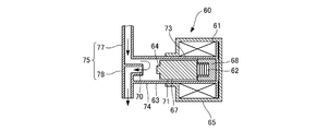
- the switching valve 60 is for switching the fuel pressure in the operation pressure fuel introduction hole 32h of the pressure regulator 20, and includes a synthetic resin bobbin 63, an electromagnetic coil 61, a valve 67, A compression coil spring 62, a shield 65 covering the outer periphery of the electromagnetic coil 61, and a stator core 68 are provided.
- the bobbin 63 includes a bobbin part 73, a cylinder part 74, and a fuel pipe part 75.
- An electromagnetic coil 61 is wound around the outer periphery of the bobbin portion 73.
- a compression coil spring 62 is accommodated inside the bobbin portion 73.
- the cylinder portion 74 and the bobbin portion 73 are formed so that their inner peripheral surfaces are the same surface, and the valve 67 is accommodated inside the cylinder portion 74 so as to be able to reciprocate.
- the fuel pipe portion 75 is formed at the end of the cylinder portion 74, and is used to return the fuel into the fuel tank 2 and the fuel inflow tube 77 through which the fuel flows in via the operation pressure outlet 21 c of the pressure regulator 20.
- the fuel outflow pipe 78 and an opening end portion 70 that forms an opening toward the inside of the cylinder portion 74 are provided.
- the valve 67 is made of a substantially cylindrical magnetic body, and has an armature portion 71 and a seal portion 64 provided on one end face. The valve 67 moves in the cylinder part 74 and the seal part 64 is pressed against the opening end part 70, so that the communication between the flow path in the fuel inflow pipe 77 and the flow path in the fuel outflow pipe 78 is prevented. It has become.
- the compression coil spring 62 urges the valve 67 in a direction to prevent communication between the flow path in the fuel inflow pipe 77 and the flow path in the fuel outflow pipe 78.
- the switching valve 60 configured as described above When the switching valve 60 configured as described above is in an ON state in which the electromagnetic coil 61 is energized, the valve 67 resists the biasing force of the compression coil spring 62 by the electromagnetic coil 61 as shown in FIG.
- the flow path in the fuel inflow pipe 77 and the flow path in the fuel outflow pipe 78 are communicated. Therefore, the fuel that has flowed into the fuel inflow pipe 77 is discharged from the fuel outflow pipe 78 through the cylinder portion 74.
- the switching valve 60 is controlled to be turned on by the ECU 51 as shown in FIG.
- the seal portion 64 of the valve 67 is separated from the opening end portion 70, and the flow path in the fuel inflow pipe 77 and the flow path in the fuel outflow pipe 78 communicate with each other. Therefore, the operation pressure fuel introduction hole 32h communicates with the inside of the fuel tank 2, and both the discharge hole 31h and the operation pressure fuel introduction hole 32h are at atmospheric pressure. Therefore, only the fuel inside the pressure regulating chamber 23 biases the pressure regulating member 22 in the valve opening direction. That is, the effective pressure receiving area of the pressure adjusting member 22 is only the annular pressure receiving surface 24 a of the partition wall portion 24.
- the thrust in the valve closing direction of the movable valve body 25 is increased, and the amount of deflection of the compression coil spring 27 that biases the movable valve body 25 in the valve closing direction is reduced, so that the movable valve body 25 is The first valve seat portion 31 and the second valve seat portion 32 are displaced in the valve closing direction.
- the switching valve 60 is controlled to be turned off by the ECU 51 as shown in FIG.
- the seal portion 64 of the valve 67 contacts the opening end portion 70, and communication between the flow path in the fuel inflow pipe 77 and the flow path in the fuel outflow pipe 78 is prevented. Therefore, the fuel inflow pipe 77 and the operation pressure fuel introduction hole 32h of the pressure regulator 20 are closed at the downstream end of the fuel, so that the fuel pressure in the operation pressure fuel introduction hole 32h is in the pressure regulating chamber 23. It becomes equal to the fuel pressure. That is, only the discharge hole 31h becomes atmospheric pressure, and the fuel inside the pressure regulating chamber 23 and the fuel in the operation pressure fuel introduction hole 32h urge the pressure regulating member 22 in the valve opening direction.
- the effective pressure receiving area of the pressure adjusting member 22 is expanded, and the substantially pressure receiving surface facing the annular pressure receiving surface 24a of the partition wall 24 and the operation pressure fuel introduction hole 32h is included. Therefore, the thrust in the valve opening direction of the movable valve body portion 25 increases, and the amount of deflection of the compression coil spring 27 that biases the movable valve body portion 25 in the valve opening direction increases, so that the movable valve body portion 25 becomes the first.
- the first valve seat portion 31 and the second valve seat portion 32 are displaced in the valve opening direction.
- a vehicle equipped with the engine 1 includes an engine speed sensor 41, an air flow meter 42, an intake air temperature sensor 43, a throttle opening sensor 44, a cooling water temperature sensor 45, an accelerator opening.
- a sensor 46, a fuel temperature sensor 47, and an atmospheric pressure sensor 48 are provided. Each of these sensors outputs a signal representing a detection result to the ECU 51.
- the engine rotation speed sensor 41 detects the rotation speed of the crankshaft of the engine 1 and outputs it to the ECU 51 as the engine rotation speed Ne.
- the air flow meter 42 is arranged on the upstream side of intake air from a throttle valve (not shown), and outputs a detection signal corresponding to the intake air amount to the ECU 51.
- the intake air temperature sensor 43 is disposed in an intake manifold (not shown), and outputs a detection signal corresponding to the intake air temperature to the ECU 51.
- the throttle opening sensor 44 outputs a detection signal corresponding to the opening of the throttle valve to the ECU 51.
- the cooling water temperature sensor 45 is disposed in a water jacket formed in the cylinder block of the engine 1, and outputs a detection signal corresponding to the cooling water temperature Tw of the engine 1 to the ECU 51.
- the accelerator opening sensor 46 outputs a detection signal corresponding to the amount of depression of the accelerator pedal to the ECU 51.
- the fuel temperature sensor 47 outputs a detection signal corresponding to the temperature of the fuel flowing through the fuel passage 15 to the ECU 51.
- the atmospheric pressure sensor 48 outputs a detection signal corresponding to the atmospheric pressure to the ECU 51.
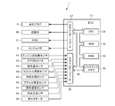
- the ECU 51 includes a CPU (Central Processing Unit) 52, a RAM (Random Access Memory) 53, a ROM (Read Only Memory) 54, a backup memory 55, and the like.
- the ECU 51 according to the present embodiment constitutes a switching control means and a fuel supply control means according to the present invention.
- the ROM 54 stores various control programs including a control program for executing the fuel pressure switching control and the fuel injection control in the cylinder 5, and a map referred to when executing these various control programs.
- the CPU 52 executes various arithmetic processes based on various control programs and maps stored in the ROM 54.
- the RAM 53 temporarily stores the calculation results by the CPU 52, data input from the above-described sensors, and the like.
- the backup memory 55 is configured by a non-volatile memory, and stores, for example, data to be saved when the engine 1 is stopped.
- the CPU 52, RAM 53, ROM 54, and backup memory 55 are connected to each other via a bus 58, and are connected to an input interface 56 and an output interface 57.
- An engine speed sensor 41, an air flow meter 42, an intake air temperature sensor 43, a throttle opening sensor 44, a cooling water temperature sensor 45, an accelerator opening sensor 46, a fuel temperature sensor 47, and an atmospheric pressure sensor 48 are connected to the input interface 56. ing. Further, the alternator 35 is connected to the input interface 56. Note that the vehicle may be mounted with an ECU other than the ECU 51, and signals output from at least some of these sensors may be input to the ECU 51 via the other ECU.
- the output interface 57 is connected to the injector 3, the spark plug 6, the FPC 17, the switching valve 60, a throttle valve (not shown), and the like.
- the ECU 51 executes various controls including fuel pressure switching control and fuel injection control based on the outputs of the various sensors described above.
- FIG. 6 is a circuit diagram around the power supply unit 34 in the present embodiment.
- the power supply unit 34 includes an alternator 35 that is mechanically connected to the engine 1 and a battery 37 that is electrically connected to the alternator 35.
- the alternator 35 is connected to the engine 1 by a belt 36, and a driving force is input from the engine 1 through the belt 36.
- the alternator 35 includes a stator stator coil, a rotor rotor coil, a rectifier, and a regulator (not shown).
- the rotor coil is connected to one terminal of the ignition switch 38 via a regulator.
- the other terminal of the ignition switch 38 is connected to the battery 37.
- the rotor coil is energized from the battery 37 via the regulator, and the rotor coil is magnetized.
- the driving force generated by the engine 1 is input to the rotor coil.
- the rotor coil rotates in conjunction with the rotation of the engine 1, an AC voltage is generated in the stator coil.
- the generated AC voltage is converted into a DC voltage by a rectifier, and this DC voltage is applied to the battery 37 as an electromotive voltage of the alternator 35.
- the electromotive force of the alternator 35 changes according to the engine speed Ne.
- the electromotive force of the alternator 35 is, for example, in the vicinity of 14 [V].
- the electromotive force of the alternator 35 is, for example, in the vicinity of 8 [V].
- the alternator 35 is connected to the ECU 51 so that the electromotive force of the alternator 35 is input to the ECU 51.
- the electromagnetic coil 61 (see FIG. 2) of the switching valve 60 is connected to the ECU 51 so that a voltage corresponding to the electromotive force of the alternator 35 is applied to the electromagnetic coil 61. That is, the voltage applied to the electromagnetic coil 61 of the switching valve 60 is obtained by detecting the electromotive force of the alternator 35.
- the ECU 51 has a transistor 69 controlled by the CPU 52 (see FIG. 5).
- the transistor 69 takes one of an ON state in which the electromotive force of the alternator 35 is applied to the electromagnetic coil 61 of the switching valve 60 and an OFF state in which the electromotive force of the alternator 35 is not applied to the electromagnetic coil 61 of the switching valve 60. It is like that.
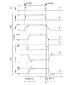
- FIG. 7 is a timing chart showing the operation of the fuel supply device 8 configured as described above.
- the location where the fuel pressure is switched from a low pressure to a high pressure in FIG. 7 will be described.
- the case where the electromotive force Eb of the alternator 35 is 12 [V] will be described as an example.
- the ECU 51 determines that a fuel pressure switching request for switching the fuel pressure from a low pressure to a high pressure has occurred before time T0 based on the traveling state of the vehicle.
- the ECU 51 detects the electromotive force Eb of the alternator 35
- the transistor 69 is turned on so that the electromotive force of the alternator 35 is applied to the electromagnetic coil 61 of the switching valve 60 at time T0 set as described later. (See solid line 81).
- Eb Eb / R (1-exp ( ⁇ t / ⁇ )) (1)
- Eb is an electromotive force of the alternator 35
- ⁇ is a time constant represented by L / R.
- R represents the electric resistance of the electromagnetic coil 61
- L represents the inductance of the electromagnetic coil 61.
- the current I supplied to the electromagnetic coil 61 increases according to the response characteristic represented by the equation (1) (see the solid line 83).
- the attractive force F applied to the valve 67 of the switching valve 60 is expressed by the following equation (2).
- n the number of turns of the electromagnetic coil 61
- I the current obtained by the above formula (1)
- R the magnetic resistance
- the movable valve body 25 of the pressure regulator 20 is displaced in the valve closing direction through an overshoot (see the solid line 86), and the fuel flowing through the fuel passage 15 becomes a high pressure (see the solid line 87).
- the convergence characteristics of the overshoot amount and displacement fluctuation of the movable valve body 25 depend on the structure of the pressure regulator 20, and can be obtained by experimental measurement in advance.
- the time T1 when the valve 67 of the switching valve 60 starts to move from the bottom dead center to the top dead center is electromagnetic according to the voltage Eb applied to the electromagnetic coil 61 as shown in the above equation (1). Since the current I supplied to the coil 61 changes, the value changes each time. That is, the time t1 from time T0 to T1 varies depending on the electromotive force Eb of the alternator 35.
- the ECU 51 predicts the time T1 by detecting the electromotive force Eb of the alternator 35 when the fuel pressure is switched from the low pressure to the high pressure, and the fuel pressure based on the predicted time T1. Is switched, and the fuel injection timing in the fuel injection control is adjusted.
- the electromotive force Eb of the alternator 35 according to the present embodiment means the electrical characteristics according to the present invention.
- the voltage detection unit of the ECU 51 can detect the electromotive force Eb of the alternator 35 at any time. Therefore, the ECU 51 detects the electromotive force Eb of the alternator 35 at the time when the fuel pressure switching request is generated, and the electromagnetic coil 61 is switched when the fuel pressure switching is started based on the electromotive force Eb. A change in the supplied current I can be predicted.
- the suction force F applied to the valve 67 of the switching valve 60 is obtained, so the ECU 51 determines that the switching valve 60 is in the OFF state.
- the timing for starting the transition to the ON state that is, the timing for starting the movement of the valve 67 can be estimated.
- FIG. 8 is a graph showing the time from when the voltage Eb is applied to the electromagnetic coil 61 until the valve 67 starts moving in the switching valve 60 having the current characteristic of the above formula (1).
- Lines 89 to 92 are obtained by calculating the time change of the current I (t) when the electromotive force Eb of the alternator 35 is 14 [V], 12 [V], 10 [V], and 8 [V], respectively.
- the points 93 to 96 are the valves 67 from the time when the voltage is applied to the electromagnetic coil 61 when the electromotive force Eb of the alternator 35 is 14 [V], 12 [V], 10 [V] and 8 [V], respectively. This is an actual measurement of the time it takes to start moving.
- the valve 67 of the switching valve 60 starts to move when the suction force by the electromagnetic coil 61 becomes larger than the biasing force by the compression coil spring 62.
- a broken line 97 represents a current value in which the biasing force by the compression coil spring 62 and the attractive force by the electromagnetic coil 61 are balanced, and the region above the broken line 97 is higher than the biasing force by the compression coil spring 62.
- the suction force by the electromagnetic coil 61 is increased, and the valve 67 shifts to the open state.
- both the electromotive force Eb of the alternator 35 and the timing at which the valve 67 starts moving that is, the switching delay time t1 from the time T0 to the time T1 are substantially the same when calculated and measured. It can be seen that there is a correlation between the switching delay time and the electromotive force Eb.
- FIG. 9 is a switching delay time map in which the electromotive force Eb of the alternator 35 is associated with the switching delay time t1.
- This switching delay time map is created based on experimental results as shown in FIG.
- the ECU 51 stores a switching delay time map indicating the relationship between the electromotive force Eb and the switching delay time t1 in the ROM 54 in advance.
- the switching delay time t1 is calculated with reference to FIG.
- the fuel injection amount injected into the combustion chamber of each cylinder 5 when the injector 3 is opened is determined according to the valve opening time and the fuel pressure of the injector 3.
- FIG. 10 is a graph showing the relationship between the fuel pressure and the fuel injection amount when the valve opening time of the injector 3 is the same.
- the fuel injection amount by the injector 3 is proportional to the square root of the fuel pressure. Therefore, when the ECU 51 calculates the amount of fuel supplied to the combustion chamber of each cylinder 5 based on the vehicle speed, the accelerator opening, etc., the valve opening time of the injector 3 is set according to the fuel pressure. .
- the fuel supply device 8 includes a fuel pressure switching control in which the ECU 51 calculates the switching delay time t1 by the method described above, and estimates the time at which the fuel pressure completely shifts from the low pressure to the high pressure.
- Fuel is supplied to the combustion chamber at a desired fuel injection amount by cooperative control in which fuel injection control for controlling timing is executed in cooperation. As a result, the actual air-fuel ratio deviates from the target air-fuel ratio, and deterioration of fuel consumption and exhaust purification performance are suppressed.
- the ECU 51 calculates the time from when the transistor 69 is switched to the ON state by the fuel pressure switching control until the fuel pressure is completely shifted from the low pressure to the high pressure, and at the next time by the fuel injection control.
- the fuel injection timing is calculated.
- the timing for turning on the transistor 69 is set so that the shift of the fuel pressure has already been completed at the calculated fuel injection timing.
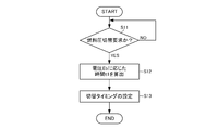
- the following processing is executed at a predetermined timing by the CPU 52 constituting the ECU 51 and realizes a program that can be processed by the CPU 52.
- the ECU 51 first acquires the traveling state of the vehicle and determines whether or not a fuel pressure switching request has occurred (step S11). Specifically, the ECU 51 determines whether the vehicle is warming up or whether the fuel is hot based on signals input from various sensors such as the coolant temperature sensor 45 and the fuel temperature sensor 47. When it is determined that the fuel pressure is warming up or at a high fuel temperature, the fuel pressure is maintained at a high pressure state. Maintain low pressure.
- the ECU 51 determines that a fuel pressure switching request has occurred when the fuel pressure is low or when either of the warming up conditions and the high fuel temperature are met.
- step S11 If the ECU 51 determines that a fuel pressure switching request has occurred (YES in step S11), the ECU 51 proceeds to step S12, and if it determines that a fuel pressure switching request has not occurred (NO in step S11). Return to START.
- the ECU 51 calculates a switching delay time t1 (step S12). Specifically, the ECU 51 detects the electromotive force Eb of the alternator 35 by the voltage detection unit. Then, the switching delay time t1 is calculated based on the switching delay time map described above.
- the ECU 51 refers to the injection timing by the fuel injection control, and sets the switching timing so that the switching of the fuel pressure does not overlap with the timing at which the fuel is injected (step S13). In this case, as described above, the ECU 51 sets the switching timing forward as the electromotive force Eb of the alternator 35 is lower, thereby avoiding the arrival of the fuel injection timing before the end of the switching of the fuel pressure. . It should be noted that the ECU 51 does not set the switching timing so that the switching of the fuel pressure does not overlap with the timing at which the fuel is injected, so that the variation in the fuel pressure becomes equal to or less than a predetermined value at the timing at which the fuel is injected. The switching timing may be set.
- the ECU 51 changes the timing of the fuel pressure switching control for the switching valve 60 according to the electrical characteristics input to the switching valve 60. can do. Therefore, even when the switching time of the state of the switching valve 60 differs according to the electrical characteristics, it is possible to reduce the influence on the fuel injection control by making the switching timing variable. For this reason, the timing at which the switching instruction is given and the fuel injection timing are optimized, and even when the fuel pressure is switched, the actual fuel injection amount can be prevented from deviating from the desired fuel injection amount. In addition, the accuracy of fuel injection control can be improved, and fuel consumption can be improved.
- the ECU 51 suppresses the influence of the electrical characteristics on the fuel pressure control by advancing the switching timing when the state of the switching valve 60 starts switching late compared with the case where switching starts earlier. it can. Therefore, in the present embodiment, when the value representing the electrical characteristics for the switching valve 60 is small, the electrical characteristics are set to the fuel pressure control by setting the switching timing to be earlier than when the value is large. The influence given can be suppressed.
- the ECU 51 can calculate the timing at which the state of the switching valve 60 is switched based on the magnitude of the electromotive force Eb of the alternator 35. Therefore, it is not necessary to directly detect the fuel pressure of the fuel supplied to the injector 3, and it is not necessary to provide a sensor for detecting the fuel pressure. Therefore, it is possible to improve the accuracy of the fuel pressure switching control at a low cost.
- the ECU 51 can set the timing at which the state of the switching valve 60 starts to switch based on the electrical characteristics. Therefore, the time required for switching the state of the switching valve 60 and the time required for the fuel pressure to switch to the steady state are measured in advance, thereby predicting the time for the fuel pressure to reach the steady state. Is possible.
- the fuel pressure is regulated in two stages by making the area where the pressure regulating member 22 receives the fuel pressure variable. Therefore, the fuel pressure supplied to the injector 3 can be controlled in two stages without making the inside of the pressure regulator 20 into three chambers or providing two pressure regulators 20. For this reason, the fuel supply device 8 can be reduced in size.
- the ECU 51 may execute similar fuel pressure switching control even when the fuel pressure is switched from high pressure to low pressure.
- the fuel supply device 8 includes the same components as the components shown in FIGS.
- the ECU 51 sets the fuel pressure when the warm-up of the vehicle is finished or the fuel temperature is lowered in a state where the fuel pressure is set to a high pressure when the vehicle is warmed up or when the fuel is hot. Fuel pressure switching control for decreasing the pressure from a high pressure to a low pressure is executed.
- a timing chart showing the operation of the fuel supply device 8 configured as described above will be described with reference to FIG.
- the electromotive force Eb of the alternator 35 is 12 [V]
- a description will be given of a place where the fuel pressure is switched from a high pressure to a low pressure in FIG.
- the ECU 51 switches the fuel pressure from the high pressure to the low pressure when the warming up of the vehicle is finished or the fuel temperature is lowered while the fuel pressure is set to a high pressure when the vehicle is warming up or when the fuel temperature is high. It is determined that a fuel pressure switching request has occurred.
- the ECU 51 shifts the transistor 69 from the ON state to the OFF state so that the electromotive force of the alternator 35 applied to the electromagnetic coil 61 of the switching valve 60 is cut off at time T0 set as described later. (See solid line 81).
- the suction force F applied to the valve 67 of the switching valve 60 is expressed by the above-described equations (2) and (3). Therefore, when the current I supplied to the electromagnetic coil 61 decreases according to the above equation (4), the attractive force of the electromagnetic coil 61 against the valve 67 decreases according to the equation (2).
- the convergence of the overshoot amount and displacement fluctuation of the movable valve body 25 can be obtained in advance by experimental measurement.
- the time t1 ′ (time T1 to T1 ′) required for the valve 67 of the switching valve 60 to reach the bottom dead center from the top dead center can also be obtained in advance by experimental measurement.
- the time T1 at which the valve 67 starts moving from the top dead center to the bottom dead center depends on the voltage Eb applied to the electromagnetic coil 61 at the start of switching, as shown in the above equation (4). As the current I supplied to the electromagnetic coil 61 changes, it fluctuates. That is, the time T1 varies depending on the electromotive force of the alternator 35.
- the ECU 51 predicts the time T1 by detecting the electromotive force Eb of the alternator 35 when switching the fuel pressure from the high pressure to the low pressure, and the fuel pressure based on the predicted time T1.
- the switching timing is controlled, and the fuel injection timing in the fuel injection control is adjusted by cooperative control.
- the voltage detection unit of the ECU 51 can detect the electromotive force Eb of the alternator 35 at any time. Therefore, the ECU 51 detects the electromotive force Eb of the alternator 35 at the time when the fuel pressure switching request is generated, and the electromagnetic coil 61 is switched when the fuel pressure switching is started based on the electromotive force Eb. A change in the supplied current I can be predicted. Therefore, the electromotive force Eb of the alternator 35 according to the present embodiment constitutes the electrical characteristics according to the present invention.
- the ECU 51 can estimate the timing at which the switching valve 60 shifts from the ON state to the OFF state. ing.
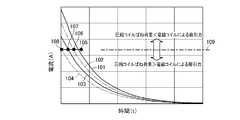
- FIG. 12 is a graph showing the time from when the voltage applied to the electromagnetic coil 61 is turned off until the valve 67 starts moving in the switching valve 60 having the current characteristic of the above formula (4).
- Lines 101 to 104 are obtained by calculating the time change of the current I (t) when the electromotive force Eb of the alternator 35 is 14 [V], 12 [V], 10 [V], and 8 [V], respectively. .
- the electromotive force Eb of the alternator 35 is 14 [V], 12 [V], 10 [V], and 8 [V]
- the voltage applied to the electromagnetic coil 61 is OFF. The time from when the valve 67 starts until the valve 67 starts to move is actually measured.
- a broken line 109 represents a current value in which the biasing force by the compression coil spring 62 and the attractive force by the electromagnetic coil 61 are balanced. In a region below the broken line 109, the broken line 109 is larger than the attractive force by the electromagnetic coil 61. The urging force by the compression coil spring 62 increases, and the valve 67 shifts to the closed state.
- the relationship between the electromotive force Eb of the alternator 35 and the switching delay time t1 from when the transistor 69 is turned off to when the valve 67 starts to move is approximately one when calculated and measured. It can be seen that there is a correlation between the switching delay time and the electromotive force Eb.
- FIG. 13 is a switching delay time map in which the electromotive force Eb of the alternator 35 is associated with the switching delay time t1.
- the ECU 51 stores a map indicating the relationship between the electromotive force Eb and the switching delay time t1 in advance in the ROM 54.
- the ECU 51 acquires a signal representing the electromotive force Eb of the alternator 35, the ECU 51 refers to the map and switches the switching delay.
- the time t1 is calculated.
- the fuel injection amount injected into the combustion chamber when the injector 3 is opened is determined according to the valve opening time and the fuel pressure of the injector 3. Therefore, when the ECU 51 calculates the amount of fuel supplied to the combustion chamber in the combustion stroke of each cylinder 5 based on the vehicle speed, the accelerator opening, etc., the valve opening time of the injector 3 is set according to the fuel pressure. It has become.
- the fuel supply device 8 calculates the switching delay time t1 by the method described above by the ECU 51, and estimates the time when the fuel pressure completely shifts from the high pressure to the low pressure, A desired amount of fuel is injected into the combustion chamber by cooperative control in which fuel injection control for controlling the injection timing is executed in a coordinated manner. As a result, the actual air-fuel ratio deviates from the target air-fuel ratio, and the deterioration of the fuel consumption or the exhaust purification performance is suppressed.
- the ECU 51 calculates, for example, the time from when the transistor 69 shifts to the OFF state by the fuel pressure switching control until the fuel pressure completely shifts from the high pressure to the low pressure, and at the next time by the fuel injection control.
- the fuel injection timing is calculated.
- the timing for turning off the transistor 69 is set so that the transition of the fuel pressure has already ended at the calculated fuel injection timing.
- the ECU 51 is configured to advance the timing for turning off the transistor 69 as the electromotive force Eb of the alternator 35 is smaller.
- the following processing is executed at a predetermined timing by the CPU 52 constituting the ECU 51 and realizes a program that can be processed by the CPU 52.
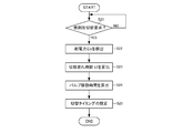
- the ECU 51 first acquires the traveling state of the vehicle and determines whether or not a fuel pressure switching request has occurred (step S21). Specifically, the ECU 51 determines whether the vehicle is warming up or whether the fuel is hot based on signals input from various sensors such as the coolant temperature sensor 45 and the fuel temperature sensor 47. When it is determined that the fuel pressure is warming up or at a high fuel temperature, the fuel pressure is maintained at a high pressure state. Maintain low pressure.
- the ECU 51 determines that a fuel pressure switching request has occurred when neither the warm-up nor the high fuel temperature is applicable.
- step S21 If the ECU 51 determines that a fuel pressure switching request has occurred (YES in step S21), the ECU 51 proceeds to step S22, and if it determines that a fuel pressure switching request has not occurred (NO in step S21). Return to START.
- step S22 the ECU 51 detects the electromotive force Eb of the alternator 35.
- step S23 the ECU 51 calculates a switching delay time t1 (step S23). Specifically, the ECU 51 calculates the switching delay time t1 based on the electromotive force Eb of the alternator 35 detected in step S22 and the switching delay time map described above.
- the ECU 51 calculates the movement time of the valve 67 (step S24). Note that the movement time of the valve 67 does not depend on the electromotive force Eb of the alternator 35, and is thus obtained in advance by experimental measurement and stored in the ROM 54. Further, after the movement of the valve 67 is finished and the fuel pressure is decreased from the high pressure to the low pressure, the time until the fluctuation of the fuel pressure converges and becomes a steady state is obtained in advance by experimental measurement and stored in the ROM 54. Keep it.
- the ECU 51 refers to the injection timing by the fuel injection control, and sets the switching timing so that the switching of the fuel pressure does not overlap with the timing at which the fuel is injected (step S25).
- the ECU 51 sums up the switching delay time t1 calculated in step S23 and the times stored in the ROM 54 in step S24, and calculates the time required from the start of fuel pressure switching to the convergence of fuel pressure fluctuations.
- the switching timing is set forward so that, for example, the arrival of the fuel injection timing before the end of the switching of the fuel pressure is avoided.
- the ECU 51 changes the timing of the fuel pressure switching control for the switching valve 60 according to the electrical characteristics input to the switching valve 60. can do. Therefore, even when the switching time of the state of the switching valve 60 differs according to the electrical characteristics, it is possible to reduce the influence on the fuel injection control by making the switching timing variable. For this reason, the timing at which the switching instruction is given and the fuel injection timing are optimized, and even when the fuel pressure is switched, the actual fuel injection amount can be prevented from deviating from the desired fuel injection amount. In addition, the accuracy of fuel injection control can be improved, and fuel consumption can be improved.
- the ECU 51 suppresses the influence of the electrical characteristics on the fuel pressure control by advancing the switching timing when the state of the switching valve 60 starts switching late compared with the case where switching starts earlier. it can. Therefore, in the present embodiment, when the value representing the electrical characteristics for the switching valve 60 is large, the electrical characteristics are used for fuel pressure control by setting the switching timing earlier than when the value is small. The influence given can be suppressed.
- the ECU 51 can calculate the timing at which the state of the switching valve 60 is switched based on the magnitude of the electromotive force Eb of the alternator 35. Therefore, it is not necessary to directly detect the fuel pressure of the fuel supplied to the injector 3, and it is not necessary to provide a sensor for detecting the fuel pressure. Therefore, it is possible to improve the accuracy of the fuel pressure switching control at a low cost.
- the ECU 51 can set the timing at which the state of the switching valve 60 starts to switch based on the electrical characteristics. Therefore, the time required for switching the state of the switching valve 60 and the time required for the fuel pressure to switch to the steady state are measured in advance, thereby predicting the time for the fuel pressure to reach the steady state. Is possible.
- the fuel pressure is regulated in two stages by making the area where the pressure regulating member 22 receives the fuel pressure variable. Therefore, the fuel pressure supplied to the injector 3 can be controlled in two stages without making the inside of the pressure regulator 20 into three chambers or providing two pressure regulators 20. For this reason, the fuel supply device 8 can be reduced in size.
- the ECU 51 when calculating the switching delay time t1, the ECU 51 refers to the injection timing by the fuel injection control, and based on the injection timing and the calculated switching delay time t1, The case where the switching timing is advanced so as not to overlap with the fuel injection timing has been described. However, as will be described below as a third embodiment, when the ECU 51 can detect the current supplied to the electromagnetic coil 61, the switching delay time t1 is set based on the detection result. It may be calculated.
- the fuel supply device 8 includes the same components as the components shown in FIGS.
- the ECU 51 has a disconnection monitor 59, and constitutes a disconnection detection means according to the present invention.
- the disconnection monitor 59 detects the magnitude of the current I supplied to the electromagnetic coil 61 of the switching valve 60, and transmits a signal representing the detected result to the CPU 52. Thereby, ECU51 judges whether the disconnection has generate
- FIG. 1
- the ECU 51 when a fuel pressure switching request is generated, switches the voltage applied to the electromagnetic coil 61 of the switching valve 60, and from the disconnection monitor 59 to the electromagnetic coil 61 of the switching valve 60.
- the time for the switching valve 60 to shift from the closed state to the open state is estimated.
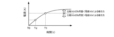
- the ECU 51 determines that a fuel pressure switching request has occurred at time T0 and shifts the transistor 69 from the OFF state to the ON state, the electromotive force of the alternator 35 is applied to the electromagnetic coil 61. Eb is applied. At this time, the current I (t) supplied to the electromagnetic coil 61 follows the above formula (1) as in the first embodiment.
- the ECU 51 detects the value of the current I at time Td immediately after the transistor 69 is switched from the OFF state to the ON state, the ECU 51 separates from the bottom dead center where the seal portion 64 of the valve 67 contacts the opening end portion 70. A time T1 at which movement starts in the direction of the dead center is calculated. Therefore, the current I (t) supplied to the electromagnetic coil 61 according to the present embodiment constitutes the electrical characteristics according to the present invention.
- the ECU 51 stores in advance the time from the time T1 at which the valve 67 starts moving to the time T3 when the fuel pressure is high and reaches a steady state through overshoot. I remember it.
- the ECU 51 detects the magnitude of the current I supplied to the electromagnetic coil 61 at time Td after the switching request is generated, thereby calculating the time when the fuel pressure in the fuel passage 15 becomes a high-pressure steady state. By adjusting the fuel injection timing by the fuel injection control based on this time, it becomes possible to inject the fuel with the fuel pressure substantially matching the target fuel pressure.
- the following processing is executed at a predetermined timing by the CPU 52 constituting the ECU 51 and realizes a program that can be processed by the CPU 52.
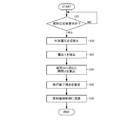
- the ECU 51 first determines whether or not a fuel pressure switching request has occurred (step S31). This determination is performed, for example, by the same method as in step S11 described above.
- the ECU 51 switches the voltage applied to the electromagnetic coil 61 of the switching valve 60 by switching the transistor 69 from the OFF state to the ON state (step S32).
- the ECU 51 detects the current I supplied to the electromagnetic coil 61 immediately after the voltage is switched (step S33).
- the ECU 51 calculates the switching delay time t1 based on the magnitude of the current detected in step S33 (step S34).
- the switching delay time t1 for example, the correspondence between the current value at the time Td and the switching delay time t1 is experimentally measured in advance, and a switching delay time map representing this relationship is stored in the ROM 54.
- the ECU 51 detects the current value in step S33, it refers to the switching delay time map stored in the ROM 54 and calculates the switching delay time t1.
- the ECU 51 estimates the time when the fuel pressure shifts to a steady state (step S35). As described above, the time from when the valve 67 starts to move and the fuel pressure starts to change to the steady state through the overshoot exceeding the target fuel pressure is the start time of the alternator 35. Since it is hardly influenced by the electric power Eb, it can be obtained by experimental measurement in advance.
- the ECU 51 reflects the time calculated in step S35 in the fuel injection control (step S36). For example, the ECU 51 interrupts fuel injection until the time calculated in step S35 has elapsed.
- the ECU 51 calculates the time for switching the state of the switching valve 60 according to the electrical characteristics input to the switching valve 60. be able to. Therefore, even when the switching time of the switching valve 60 is different depending on the electrical characteristics, it is possible to reduce the influence on the fuel injection control by calculating the switching time of the switching valve 60. Become. For this reason, the timing at which the switching instruction is given and the fuel injection timing are optimized, and even when the fuel pressure is switched, the actual fuel injection amount can be prevented from deviating from the desired fuel injection amount. In addition, the accuracy of fuel injection control can be improved, and fuel consumption can be improved.
- the ECU 51 can predict the time when the state of the switching valve 60 starts to switch. Thereby, the timing at which the switching instruction is given and the fuel injection timing are optimized, and even when the fuel pressure is switched, the actual fuel injection amount can be prevented from deviating from the desired fuel injection amount.
- the fuel pressure at a certain time is predicted by calculating the time required for the fuel pressure to be switched, and the fuel pressure is calculated based on the predicted fuel pressure at the time.
- the accuracy of the fuel injection amount can be increased.
- the ECU 51 can calculate the timing at which the state of the switching valve 60 is switched based on the magnitude of the current supplied to the switching valve 60. Therefore, it is not necessary to directly detect the fuel pressure of the fuel supplied to the injector 3, and it is not necessary to provide a sensor for detecting the fuel pressure. For this reason, it is possible to improve the accuracy of the fuel pressure switching control at a low cost.
- the ECU 51 has described the case where the switching delay time t1 is calculated based on the current value detected at the time td immediately after the transistor 69 shifts from the OFF state to the ON state. However, the ECU 51 always obtains the current I detected by the disconnection monitor 59, and sets the time point when the magnitude of the current I reaches the magnitude necessary for starting the movement of the valve 67 as time T1. It may be.
- the ECU 51 has been described as an example in which the switching delay time map is stored in the ROM 54 in advance. However, the ECU 51 stores a formula for calculating the time T1 from the current value at the time Td in the ROM 54, and when the current value is detected in step S33, the ECU 51 calculates the time T1 based on the formula stored in the ROM 54. May be.
- the ECU 51 switches the fuel pressure from the low pressure to the high pressure.
- the ECU 51 calculates the switching delay time t1 based on the current I and reflects it in the injection timing of the fuel injection control even when the fuel pressure is switched from the high pressure to the low pressure. You may do it.
- the fuel pressure switching time until shifting to a low pressure and the fuel pressure fluctuation time until the fuel pressure shifts to a steady state at a constant fuel pressure are stored in the ROM 54 in advance.
- the ECU 51 then generates a switching delay time t1 from the time T0 when the switching request for the fuel pressure is generated and the transistor 69 is switched from the ON state to the OFF state until the time T1 at which the valve 67 starts to move. Is calculated based on the valve travel time, fuel pressure switching time, and fuel pressure fluctuation time stored in the ROM 54, and the time until the fuel pressure is switched to a low pressure and becomes a steady state is calculated.
- the ECU 51 controls the fuel pressure switching control and the fuel injection control in a coordinated manner so that the fuel injection timing is delayed by the fuel injection control from the time when the fuel pressure becomes low.
- the fuel supply apparatus optimizes the timing for performing the switching instruction and the fuel injection timing, and the actual fuel injection amount deviates from the desired fuel injection amount even when the fuel pressure is switched. By suppressing this, there is an effect that fuel efficiency can be improved, and it is useful for a fuel supply device that regulates the fuel stored in the fuel tank and supplies the fuel to the fuel consumption unit.
Landscapes
- Engineering & Computer Science (AREA)
- Chemical & Material Sciences (AREA)
- Combustion & Propulsion (AREA)
- Mechanical Engineering (AREA)
- General Engineering & Computer Science (AREA)
- Electrical Control Of Air Or Fuel Supplied To Internal-Combustion Engine (AREA)
- Fuel-Injection Apparatus (AREA)
- Combined Controls Of Internal Combustion Engines (AREA)
- Output Control And Ontrol Of Special Type Engine (AREA)
Priority Applications (5)
| Application Number | Priority Date | Filing Date | Title |
|---|---|---|---|
| US13/393,377 US8944030B2 (en) | 2011-08-01 | 2011-08-01 | Fuel supply apparatus |
| PCT/JP2011/004362 WO2013018131A1 (ja) | 2011-08-01 | 2011-08-01 | 燃料供給装置 |
| JP2012508695A JP5337911B2 (ja) | 2011-08-01 | 2011-08-01 | 燃料供給装置 |
| CN201180003598.4A CN103261667B (zh) | 2011-08-01 | 2011-08-01 | 燃料供给装置 |
| EP11818968.7A EP2573380B1 (de) | 2011-08-01 | 2011-08-01 | Kraftstoffzufuhrvorrichtung |
Applications Claiming Priority (1)
| Application Number | Priority Date | Filing Date | Title |
|---|---|---|---|
| PCT/JP2011/004362 WO2013018131A1 (ja) | 2011-08-01 | 2011-08-01 | 燃料供給装置 |
Publications (1)
| Publication Number | Publication Date |
|---|---|
| WO2013018131A1 true WO2013018131A1 (ja) | 2013-02-07 |
Family
ID=47626136
Family Applications (1)
| Application Number | Title | Priority Date | Filing Date |
|---|---|---|---|
| PCT/JP2011/004362 Ceased WO2013018131A1 (ja) | 2011-08-01 | 2011-08-01 | 燃料供給装置 |
Country Status (5)
| Country | Link |
|---|---|
| US (1) | US8944030B2 (de) |
| EP (1) | EP2573380B1 (de) |
| JP (1) | JP5337911B2 (de) |
| CN (1) | CN103261667B (de) |
| WO (1) | WO2013018131A1 (de) |
Families Citing this family (5)
| Publication number | Priority date | Publication date | Assignee | Title |
|---|---|---|---|---|
| KR101873814B1 (ko) * | 2013-12-19 | 2018-08-02 | 삼성전자주식회사 | 디스플레이 장치 및 디스플레이 장치의 컨텐츠 추천 방법 |
| US9638348B2 (en) * | 2015-05-01 | 2017-05-02 | Caterpillar Inc. | Gas flow limiter for a fuel system and process for use thereof |
| JP6387998B2 (ja) * | 2016-03-30 | 2018-09-12 | 株式会社デンソー | プレッシャレギュレータ及び燃料供給装置 |
| US10540040B2 (en) * | 2016-06-30 | 2020-01-21 | Stmicroelectronics Asia Pacific Pte Ltd | Architecture and driving methods for minimizing power losses in touch panel |
| JP6425859B1 (ja) * | 2018-06-25 | 2018-11-21 | 株式会社小松製作所 | 作業車両の燃費計測システム及び作業車両の燃費計測方法 |
Citations (5)
| Publication number | Priority date | Publication date | Assignee | Title |
|---|---|---|---|---|
| JP2009144686A (ja) | 2007-12-18 | 2009-07-02 | Aisan Ind Co Ltd | 調圧弁及び燃料供給装置 |
| JP2009250211A (ja) | 2008-04-10 | 2009-10-29 | Fuji Heavy Ind Ltd | エンジンの制御装置 |
| JP2010156228A (ja) * | 2008-12-26 | 2010-07-15 | Toyota Motor Corp | 内燃機関の燃料供給装置 |
| JP2010185449A (ja) * | 2009-01-13 | 2010-08-26 | Aisan Ind Co Ltd | 燃料供給装置 |
| WO2011001478A1 (ja) * | 2009-07-03 | 2011-01-06 | トヨタ自動車株式会社 | 燃料供給装置 |
Family Cites Families (17)
| Publication number | Priority date | Publication date | Assignee | Title |
|---|---|---|---|---|
| JP3333407B2 (ja) * | 1996-10-17 | 2002-10-15 | 株式会社ユニシアジェックス | 直噴式ガソリン内燃機関の燃料供給装置 |
| JP3572433B2 (ja) * | 1997-01-31 | 2004-10-06 | 日産自動車株式会社 | ディーゼルエンジン用燃料噴射ポンプの燃料噴射時期制御装置 |
| US5967119A (en) * | 1998-03-11 | 1999-10-19 | General Motors Corporation | Electronically variable pressure control |
| DE69905685T2 (de) * | 1998-11-19 | 2003-10-02 | Mitsubishi Jidosha Kogyo K.K., Tokio/Tokyo | Kraftstoffeinspritzvorrichtung der Akkumulatorgattung |
| EP1008741B1 (de) * | 1998-11-20 | 2003-04-02 | Mitsubishi Jidosha Kogyo Kabushiki Kaisha | Kraftstoffeinspritzvorrichtung der Accumulatorgattung |
| EP1155233B1 (de) * | 1999-02-24 | 2005-01-19 | Siemens Aktiengesellschaft | Regelorgan zur steuerung einer druckverstärkung von kraftstoff für einen kraftstoffinjektor |
| JP3998432B2 (ja) * | 2001-04-05 | 2007-10-24 | 三菱ふそうトラック・バス株式会社 | 蓄圧式燃料噴射装置 |
| DE10144800A1 (de) * | 2001-09-12 | 2003-04-03 | Bosch Gmbh Robert | Verfahren, Computerprogramm, Steuer- und/oder Regelgerät zum Betreiben einer Brennkraftmaschine, sowie Kraftstoffsystem für eine Brennkraftmaschine |
| JP2003148214A (ja) | 2001-11-09 | 2003-05-21 | Bosch Automotive Systems Corp | 弁駆動用アクチュエータ駆動タイミング調整回路、インジェクタ及び燃料噴射装置 |
| JP4013529B2 (ja) * | 2001-11-16 | 2007-11-28 | 三菱ふそうトラック・バス株式会社 | 燃料噴射装置 |
| JP3855861B2 (ja) * | 2002-06-28 | 2006-12-13 | トヨタ自動車株式会社 | 内燃機関の高圧燃料供給装置 |
| JP4148127B2 (ja) * | 2003-12-12 | 2008-09-10 | 株式会社デンソー | 燃料噴射装置 |
| JP2005307747A (ja) * | 2004-04-16 | 2005-11-04 | Mitsubishi Electric Corp | 内燃機関の燃料供給装置 |
| JP4538851B2 (ja) * | 2006-02-15 | 2010-09-08 | 株式会社デンソー | 筒内噴射式の内燃機関の燃圧制御装置 |
| JP4924533B2 (ja) * | 2008-05-13 | 2012-04-25 | 株式会社デンソー | 内燃機関の燃料噴射制御システム |
| JP4815502B2 (ja) * | 2009-03-26 | 2011-11-16 | 日立オートモティブシステムズ株式会社 | 内燃機関の制御装置 |
| WO2011099055A1 (ja) | 2010-02-10 | 2011-08-18 | トヨタ自動車株式会社 | 流体圧力調整装置および燃料供給装置 |
-
2011
- 2011-08-01 JP JP2012508695A patent/JP5337911B2/ja not_active Expired - Fee Related
- 2011-08-01 WO PCT/JP2011/004362 patent/WO2013018131A1/ja not_active Ceased
- 2011-08-01 EP EP11818968.7A patent/EP2573380B1/de not_active Not-in-force
- 2011-08-01 US US13/393,377 patent/US8944030B2/en not_active Expired - Fee Related
- 2011-08-01 CN CN201180003598.4A patent/CN103261667B/zh not_active Expired - Fee Related
Patent Citations (5)
| Publication number | Priority date | Publication date | Assignee | Title |
|---|---|---|---|---|
| JP2009144686A (ja) | 2007-12-18 | 2009-07-02 | Aisan Ind Co Ltd | 調圧弁及び燃料供給装置 |
| JP2009250211A (ja) | 2008-04-10 | 2009-10-29 | Fuji Heavy Ind Ltd | エンジンの制御装置 |
| JP2010156228A (ja) * | 2008-12-26 | 2010-07-15 | Toyota Motor Corp | 内燃機関の燃料供給装置 |
| JP2010185449A (ja) * | 2009-01-13 | 2010-08-26 | Aisan Ind Co Ltd | 燃料供給装置 |
| WO2011001478A1 (ja) * | 2009-07-03 | 2011-01-06 | トヨタ自動車株式会社 | 燃料供給装置 |
Also Published As
| Publication number | Publication date |
|---|---|
| CN103261667B (zh) | 2015-07-08 |
| US20130032126A1 (en) | 2013-02-07 |
| JPWO2013018131A1 (ja) | 2015-02-23 |
| EP2573380A4 (de) | 2014-12-10 |
| US8944030B2 (en) | 2015-02-03 |
| CN103261667A (zh) | 2013-08-21 |
| EP2573380A1 (de) | 2013-03-27 |
| EP2573380B1 (de) | 2018-09-26 |
| JP5337911B2 (ja) | 2013-11-06 |
Similar Documents
| Publication | Publication Date | Title |
|---|---|---|
| JP5212546B2 (ja) | 燃料供給装置 | |
| JP4081819B2 (ja) | 燃料噴射システム | |
| JP5494818B2 (ja) | 内燃機関の燃料噴射制御システム | |
| US20140251280A1 (en) | Control apparatus for internal combustion engine and control method for internal combustion engine | |
| JP5337911B2 (ja) | 燃料供給装置 | |
| US9670863B2 (en) | Apparatus and method for controlling internal-combustion engine | |
| US10508611B2 (en) | Control device and control method for internal combustion engine | |
| JP5687598B2 (ja) | 燃料供給装置 | |
| JP2007303372A (ja) | 内燃機関の燃料供給システム | |
| JP5970772B2 (ja) | 燃料供給装置 | |
| JP5556572B2 (ja) | 燃料圧力センサ診断装置 | |
| JP5181890B2 (ja) | 内燃機関の制御装置 | |
| JP5817433B2 (ja) | 燃料供給装置 | |
| JP2013032721A (ja) | 燃料供給装置 | |
| JP2013032722A (ja) | 燃料供給装置 | |
| JP4661747B2 (ja) | エンジンの停止制御装置 | |
| JP2013092058A (ja) | 燃料供給装置 | |
| JP5999038B2 (ja) | 内燃機関のegrバルブ制御装置 | |
| JP2013092059A (ja) | 燃料供給装置 | |
| JP5939212B2 (ja) | 内燃機関のegrバルブ制御装置 |
Legal Events
| Date | Code | Title | Description |
|---|---|---|---|
| ENP | Entry into the national phase |
Ref document number: 2012508695 Country of ref document: JP Kind code of ref document: A |
|
| WWE | Wipo information: entry into national phase |
Ref document number: 2011818968 Country of ref document: EP |
|
| WWE | Wipo information: entry into national phase |
Ref document number: 13393377 Country of ref document: US |
|
| NENP | Non-entry into the national phase |
Ref country code: DE |