WO2013018265A1 - Dispositif de gazéification et d'amenée de matière première - Google Patents
Dispositif de gazéification et d'amenée de matière première Download PDFInfo
- Publication number
- WO2013018265A1 WO2013018265A1 PCT/JP2012/003783 JP2012003783W WO2013018265A1 WO 2013018265 A1 WO2013018265 A1 WO 2013018265A1 JP 2012003783 W JP2012003783 W JP 2012003783W WO 2013018265 A1 WO2013018265 A1 WO 2013018265A1
- Authority
- WO
- WIPO (PCT)
- Prior art keywords
- raw material
- flow rate
- control device
- pressure type
- vapor
- Prior art date
- Legal status (The legal status is an assumption and is not a legal conclusion. Google has not performed a legal analysis and makes no representation as to the accuracy of the status listed.)
- Ceased
Links
Images


Classifications
-
- C—CHEMISTRY; METALLURGY
- C23—COATING METALLIC MATERIAL; COATING MATERIAL WITH METALLIC MATERIAL; CHEMICAL SURFACE TREATMENT; DIFFUSION TREATMENT OF METALLIC MATERIAL; COATING BY VACUUM EVAPORATION, BY SPUTTERING, BY ION IMPLANTATION OR BY CHEMICAL VAPOUR DEPOSITION, IN GENERAL; INHIBITING CORROSION OF METALLIC MATERIAL OR INCRUSTATION IN GENERAL
- C23C—COATING METALLIC MATERIAL; COATING MATERIAL WITH METALLIC MATERIAL; SURFACE TREATMENT OF METALLIC MATERIAL BY DIFFUSION INTO THE SURFACE, BY CHEMICAL CONVERSION OR SUBSTITUTION; COATING BY VACUUM EVAPORATION, BY SPUTTERING, BY ION IMPLANTATION OR BY CHEMICAL VAPOUR DEPOSITION, IN GENERAL
- C23C16/00—Chemical coating by decomposition of gaseous compounds, without leaving reaction products of surface material in the coating, i.e. chemical vapour deposition [CVD] processes
- C23C16/44—Chemical coating by decomposition of gaseous compounds, without leaving reaction products of surface material in the coating, i.e. chemical vapour deposition [CVD] processes characterised by the method of coating
- C23C16/455—Chemical coating by decomposition of gaseous compounds, without leaving reaction products of surface material in the coating, i.e. chemical vapour deposition [CVD] processes characterised by the method of coating characterised by the method used for introducing gases into reaction chamber or for modifying gas flows in reaction chamber
-
- C—CHEMISTRY; METALLURGY
- C23—COATING METALLIC MATERIAL; COATING MATERIAL WITH METALLIC MATERIAL; CHEMICAL SURFACE TREATMENT; DIFFUSION TREATMENT OF METALLIC MATERIAL; COATING BY VACUUM EVAPORATION, BY SPUTTERING, BY ION IMPLANTATION OR BY CHEMICAL VAPOUR DEPOSITION, IN GENERAL; INHIBITING CORROSION OF METALLIC MATERIAL OR INCRUSTATION IN GENERAL
- C23C—COATING METALLIC MATERIAL; COATING MATERIAL WITH METALLIC MATERIAL; SURFACE TREATMENT OF METALLIC MATERIAL BY DIFFUSION INTO THE SURFACE, BY CHEMICAL CONVERSION OR SUBSTITUTION; COATING BY VACUUM EVAPORATION, BY SPUTTERING, BY ION IMPLANTATION OR BY CHEMICAL VAPOUR DEPOSITION, IN GENERAL
- C23C16/00—Chemical coating by decomposition of gaseous compounds, without leaving reaction products of surface material in the coating, i.e. chemical vapour deposition [CVD] processes
- C23C16/44—Chemical coating by decomposition of gaseous compounds, without leaving reaction products of surface material in the coating, i.e. chemical vapour deposition [CVD] processes characterised by the method of coating
- C23C16/448—Chemical coating by decomposition of gaseous compounds, without leaving reaction products of surface material in the coating, i.e. chemical vapour deposition [CVD] processes characterised by the method of coating characterised by the method used for generating reactive gas streams, e.g. by evaporation or sublimation of precursor materials
- C23C16/4481—Chemical coating by decomposition of gaseous compounds, without leaving reaction products of surface material in the coating, i.e. chemical vapour deposition [CVD] processes characterised by the method of coating characterised by the method used for generating reactive gas streams, e.g. by evaporation or sublimation of precursor materials by evaporation using carrier gas in contact with the source material
- C23C16/4482—Chemical coating by decomposition of gaseous compounds, without leaving reaction products of surface material in the coating, i.e. chemical vapour deposition [CVD] processes characterised by the method of coating characterised by the method used for generating reactive gas streams, e.g. by evaporation or sublimation of precursor materials by evaporation using carrier gas in contact with the source material by bubbling of carrier gas through liquid source material
-
- C—CHEMISTRY; METALLURGY
- C23—COATING METALLIC MATERIAL; COATING MATERIAL WITH METALLIC MATERIAL; CHEMICAL SURFACE TREATMENT; DIFFUSION TREATMENT OF METALLIC MATERIAL; COATING BY VACUUM EVAPORATION, BY SPUTTERING, BY ION IMPLANTATION OR BY CHEMICAL VAPOUR DEPOSITION, IN GENERAL; INHIBITING CORROSION OF METALLIC MATERIAL OR INCRUSTATION IN GENERAL
- C23C—COATING METALLIC MATERIAL; COATING MATERIAL WITH METALLIC MATERIAL; SURFACE TREATMENT OF METALLIC MATERIAL BY DIFFUSION INTO THE SURFACE, BY CHEMICAL CONVERSION OR SUBSTITUTION; COATING BY VACUUM EVAPORATION, BY SPUTTERING, BY ION IMPLANTATION OR BY CHEMICAL VAPOUR DEPOSITION, IN GENERAL
- C23C16/00—Chemical coating by decomposition of gaseous compounds, without leaving reaction products of surface material in the coating, i.e. chemical vapour deposition [CVD] processes
- C23C16/44—Chemical coating by decomposition of gaseous compounds, without leaving reaction products of surface material in the coating, i.e. chemical vapour deposition [CVD] processes characterised by the method of coating
- C23C16/448—Chemical coating by decomposition of gaseous compounds, without leaving reaction products of surface material in the coating, i.e. chemical vapour deposition [CVD] processes characterised by the method of coating characterised by the method used for generating reactive gas streams, e.g. by evaporation or sublimation of precursor materials
- C23C16/4485—Chemical coating by decomposition of gaseous compounds, without leaving reaction products of surface material in the coating, i.e. chemical vapour deposition [CVD] processes characterised by the method of coating characterised by the method used for generating reactive gas streams, e.g. by evaporation or sublimation of precursor materials by evaporation without using carrier gas in contact with the source material
-
- H—ELECTRICITY
- H10—SEMICONDUCTOR DEVICES; ELECTRIC SOLID-STATE DEVICES NOT OTHERWISE PROVIDED FOR
- H10P—GENERIC PROCESSES OR APPARATUS FOR THE MANUFACTURE OR TREATMENT OF DEVICES COVERED BY CLASS H10
- H10P72/00—Handling or holding of wafers, substrates or devices during manufacture or treatment thereof
- H10P72/04—Apparatus for manufacture or treatment
- H10P72/0402—Apparatus for fluid treatment
Definitions
- the present invention relates to an improvement of a raw material vaporization supply device of a semiconductor manufacturing apparatus using a so-called metal organic chemical vapor deposition method (hereinafter referred to as MOCVD method), and is a liquid or solid raw material having a low vapor pressure. Further, the present invention relates to a raw material vaporizing and supplying apparatus that can supply raw material vapor to a process chamber while controlling the flow rate to a set flow rate with high accuracy, and can greatly simplify and downsize the apparatus structure.
- MOCVD method metal organic chemical vapor deposition method
- the raw material vaporization supply device that generates raw material vapor by heating and supplies the saturated vapor to the raw material use location is stable in the generation of raw material vapor, the amount of raw material vapor Since there are many problems in the control of the vapor pressure, the flow rate control of the raw material vapor (raw material gas), etc., its development and utilization are relatively less than other types of devices.
- the raw material vaporization supply device using this baking method supplies the raw material vapor (raw material gas) having a saturated vapor pressure generated from the raw material to the process chamber as it is, the raw material vaporization supply device using the bubbling method Various inconveniences caused by fluctuations in the concentration of the raw material gas in the process gas are eliminated, and a high utility is achieved in maintaining and improving the quality of the semiconductor product.
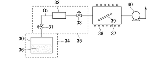
- FIG. 15 shows an example of a raw material vaporizing and supplying apparatus using the above baking method.
- the organometallic compound 36 stored in the cylinder container 30 is heated to a constant temperature in the air temperature-controlled room 34, and the cylinder container 30.
- the raw material vapor (raw material gas) Go generated therein is supplied to the process chamber 37 through the inlet / outlet valve 31, the mass flow controller 32 and the valve 33.
- 38 is a heater
- 39 is a substrate
- 40 is an evacuation pump.
- Reference numeral 35 denotes an air temperature-controlled room that warms the raw material vapor supply system such as the inlet / outlet valve 31, the mass flow controller 32, and the valve 33, and is for preventing condensation of the raw material vapor Go.
- the raw material vaporization supply apparatus of FIG. 15 first, by heating the cylinder container 30, the organometallic compound 36 evaporates, and the vapor pressure in the internal space of the container rises. Next, by opening the inlet / outlet valve 31 and the valve 33, the generated raw material vapor (raw material gas) Go is supplied to the process chamber 37 while the mass flow controller 32 controls the flow rate to a set flow rate.
- the organometallic compound 36 is trimethylindium (TMIn)
- the cylinder container 30 is heated to about 80 ° C. to 90 ° C.
- the raw material vapor supply system such as the mass flow controller 32, the inlet / outlet valve 31, and the valve 33 is heated to about 90 ° C. to 100 ° C. in the air temperature chamber 35, and the raw material vapor Go is concentrated in the mass flow controller 32 and the like. To prevent.
- the raw material vaporization supply apparatus of FIG. 15 supplies the raw material vapor Go directly to the process chamber 37, so that a desired amount of raw material is accurately fed into the process chamber 37 by controlling the flow rate of the raw material vapor Go with high accuracy. be able to.
- the first problem is the flow control accuracy of the raw material vapor (raw material gas) Go supplied to the process chamber 37 and the stability of the flow control. That is, in the raw material vaporizing and supplying apparatus shown in FIG. 15, the mass flow controller (thermal mass flow controller) 32 is used to control the supply flow rate of the raw material vapor Go, and the mass flow controller 32 is installed in the air temperature-controlled room 35. Is heated to 90 to 100 ° C. to prevent condensation of the raw material vapor Go.
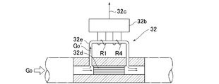
- the mass flow controller 32 generally allows a small amount of gas flow to flow through the ultrafine sensor tube 32e at a constant ratio as compared to the flow rate of the bypass group 32d, as shown in FIG. Also, a pair of control resistance wires R1 and R4 connected in series are wound around the sensor tube 32e, and a flow rate indicating a mass flow rate value monitored by the sensor circuit 32b connected thereto. The signal 32c is output.
- FIG. 16 shows the basic structure of the sensor circuit 32b.
- a series connection circuit of two reference resistors R2 and R3 is connected in parallel to the series connection of the resistance wires R1 and R4, and a bridge circuit is formed. Forming.
- a constant current source is connected to the bridge circuit, and a differential circuit having an input side connected to a connection point of the resistance lines R1 and R4 and a connection point of the reference resistors R2 and R3 is provided. The potential difference at the connection point is obtained and this potential difference is output as the flow signal 32c.
- the gas flow Go ′ flows through the sensor pipe 32e at the mass flow rate Q
- the gas flow Go ′ is heated by the heat generated by the resistance wire R1 located on the upstream side, and the resistance wire R4 on the downstream side is heated. It will flow to the wound position.
- heat transfer occurs, the resistance wire R1 is cooled, the resistance wire R4 is heated, a temperature difference, that is, a resistance value is generated between the resistance wires R1 and R4, and the potential difference generated at this time is the mass of the gas. It is approximately proportional to the flow rate. Therefore, by applying a predetermined gain to the flow rate signal 32c, the mass flow rate of the gas flow Go ′ flowing at that time can be obtained.
- the mass flow controller 32 first heats the resistance R1 portion by the gas fluid Go ′ diverted to the sensor pipe 32e. As a result, the resistance value of the resistance R1 decreases and the resistance value R2 decreases. By increasing the amount of heat of the gas fluid Go ′ flowing in, the temperature of the resistor R4 rises, the resistance value increases, and a potential difference is generated between the bridges, thereby measuring the mass flow rate of the raw material vapor Go. . Therefore, it is inevitable that temperature fluctuations occur in the raw material vapor Go ′ flowing through the fine sensor tube 32e. As a result, the temperature distribution in the vicinity of the tube 32e of the sensor of the mass flow sensor 32 becomes non-uniform.
- the second problem is an increase in the size of the raw material vaporizer.
- the cylinder container 30 and the mass flow controller 32 are arranged separately, and the cylinder container 30 and the mass flow controller 32 are arranged in different air temperature-controlled rooms 34 and 35, respectively. It is said.
- the installation space of each member constituting the raw material vaporization supply apparatus becomes relatively large, and the raw material vaporization supply apparatus cannot be greatly reduced in size.
- the present invention relates to the above-mentioned problems in the vaporizing and supplying apparatus for raw materials using the conventional baking method. Since the flow control of the raw material vapor (raw material gas) is performed using a thermal mass flow controller (mass flow controller), the temperature fluctuation of the raw material vapor Go ′ flowing through the sensor part and the temperature of the sensor part member Uniformity (temperature gradient) will occur, and this will cause the flow rate control accuracy to be reduced, and the raw material vapor Go ′ flowing through the sensor part will be easily clogged or condensed, and b.
- a thermal mass flow controller mass flow controller
- the problem is that it is difficult to reduce the size of the raw material vaporization supply device, and the raw material vapor generated in the raw material container Providing a raw material vaporization supply device for semiconductor manufacturing equipment that can be supplied to the process chamber stably without causing troubles such as clogging, while controlling the flow rate with high precision, and enabling a significant downsizing of the device. Is the main purpose of the invention.
- a source tank storing a raw material, a raw material vapor supply path for supplying the raw material vapor from the internal space of the source tank to the process chamber, and a raw material vapor interposed in the supply path and supplied to the process chamber
- a raw material vapor generated in an internal space portion of the source tank comprising a pressure type flow rate control device for controlling the flow rate, and a constant temperature heating unit for heating the source tank, the raw material vapor supply path and the pressure type flow rate control device to a set temperature. Is supplied to the process chamber while the flow rate is controlled by a pressure type flow rate control device.
- the source tank and the pressure type flow rate control device are assembled and fixed so as to be disengageable integrally.
- the purge gas supply path is connected in a branched manner to the primary side of the pressure type flow control device, and the dilution gas supply path is connected to the secondary side of the pressure type flow control device. It is connected in a branched manner.
- the invention of claim 4 is the invention of claim 1, wherein the constant temperature heating section for heating the source tank and the constant temperature heating section for heating the pressure flow control device and the raw material vapor supply path are separated.
- the heating temperature of the constant temperature heating unit, the pressure flow control device, and the heating temperature of the constant temperature heating unit of the raw material vapor supply path are controlled independently.
- the invention of claim 5 is the invention of claim 1, wherein the raw material is trimethylgallium (TMGa) or (trimethylindium (TMIn).
- the invention of claim 6 is the invention of claim 1, wherein the raw material is a solid raw material supported on a liquid or a porous carrier.
- the invention according to claim 7 is the invention according to claim 1, wherein the pressure type flow rate control device includes a control valve CV, a temperature detector T and a pressure detector P provided downstream thereof, and a pressure detector P.
- the flow rate of the raw material vapor calculated using the orifice provided on the downstream side and the detection value of the pressure detector P is corrected based on the detection value of the temperature detector T, and the predetermined raw material vapor flow rate and the An arithmetic control unit that outputs a control signal Pd that controls opening / closing of the control valve CV in a direction that reduces the difference between the calculated flow rate and the flow rate, and a flow passage portion through which the raw material vapor of the body block flows is heated to a predetermined temperature. It is made up of a heater.
- the raw material vapor in the source tank is supplied as it is to the process chamber while the flow rate is controlled by the pressure type flow rate control device.
- the concentration of raw material vapor in the process gas can be increased with high accuracy compared to the raw material vaporization supply device using the conventional bubbling method or vaporization method.
- it can be controlled easily, and high-quality semiconductor products can be manufactured.
- the pressure type flow control device has characteristics that are not easily affected by fluctuations in the pressure of the primary supply source, high-precision flow control can be performed even if the raw material vapor pressure in the source tank fluctuates slightly. Can do.
- the material vaporization and supply unit can be greatly reduced in size and the manufacturing cost can be reduced.
- FIG. 6 shows the results of a flow rate control characteristic test of Example 1, and shows the temperature, detected pressure, set flow rate when the pressure type flow rate control device is F88A type, the set pressure P 2 ′ of the vacuum pressure gauge is 1.0 Torr, The flow rate output and the measured flow rate value are shown. Each measurement value similar to FIG.
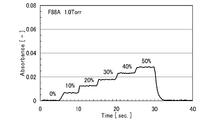
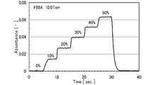
- FIG. 5 shows the relationship between the absorbance of FT-IR and the set flow rate switching time in the test of FIG.
- FIG. 7 shows the relationship between the absorbance of FT-IR and the set flow rate switching time in the test of FIG.
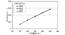
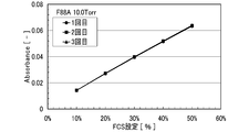
- FIG. 8 shows the relationship between the absorbance of FT-IR and the set flow rate switching time in the test of FIG. 9 shows the relationship between the flow rate setting value and the absorbance of the pressure type flow rate control device in the test of FIG.
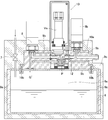
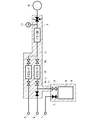
- FIG. 1 is a configuration system diagram of a raw material vaporization and supply apparatus according to an embodiment of the present invention.
- the raw material vaporization and supply apparatus includes a source tank 6 that contains a raw material 5 and a constant temperature heating that heats the source tank 6 and the like. And a pressure type flow rate control device 10 for adjusting the flow rate of the raw material vapor G ′ supplied to the process chamber 13 from the internal upper space 6a of the source tank.
- 1 is a raw material supply port
- 2 is a purge gas supply port
- 3 is a dilution gas supply port
- 4 is another gas supply port for forming a thin film
- 7 is a raw material inlet valve
- 8 and 8b are raw materials.
- Steam outlet valve, 8a is a raw material steam inlet valve
- 14 is a heater
- 15 is a substrate
- 16 is a vacuum exhaust pump
- V 1 to V 4 are valves
- L is a raw material supply path
- L 1 is a raw material steam supply path
- L 2 to L 4 represents a gas supply passage.
- the source tank 6 is made of stainless steel or the like, and contains an organic metal material such as TMG (trimethylgallium) or TMIn (trimethylindium).
- the liquid raw material 5 is supplied from the raw material supply port 1 into the source tank 6 through the supply path L.
- a cassette-type tank is used as the source tank 6 as will be described later.
- a cassette type source tank 6 filled with a highly dangerous organic metal material in advance is detachably fixed to a body block (base body, not shown) of the source gas supply device, or the source tank 6 and the pressure type flow rate control device 10 are fixed. It is good also as a structure which fixes to these integrally so that dissociation is possible.
- the organometallic material used as the raw material 5 may be a liquid, a granule, or a powder.
- the constant temperature heating unit 9 heats and holds the source tank 6 and the pressure type flow rate control device 10 at a set temperature of 40 ° C. to 120 ° C., and is formed of a heater, a heat insulating material, a temperature control unit, and the like.
- the source tank 6 and the pressure type flow rate control device 10 are integrally heated by one constant temperature heating unit 9, but the constant temperature heating unit is divided into the source tank 9 and the pressure type flow rate.
- the heating temperature of the control device 10 may be individually adjustable.
- the pressure type flow rate control device 10 is provided to the material steam supply passage L 1 on the downstream side of the source tank 6, as shown in diagram of Figure 2, the orifice 12 the raw material vapor G'which has flowed through the control valve CV It is intended to be drained through.
- the pressure type flow control device itself is publicly known, detailed description thereof is omitted here.
- the pressure type flow rate control device 10 is known as described above, but the downstream pressure P 2 of the orifice 12 (that is, the pressure P 2 on the process chamber side) and the upstream pressure P 1 of the orifice 12 (that is, the pressure P 2 )
- the downstream pressure P 2 of the orifice 12 that is, the pressure P 2 on the process chamber side
- the upstream pressure P 1 of the orifice 12 that is, the pressure P 2
- the pressure type flow control device 10 is integrally assembled to the upper wall surface of the source tank 6 so as to be detachable, and a mounting bolt 10b through which the body block 10a of the pressure type flow control device 10 is inserted.
- Vo is a drive unit (piezo element) of the control valve CV
- 9 a and 9 b are heaters of the constant temperature heating unit
- 9 c is a heat insulating material of the constant temperature heating unit 9.
- a source tank 5 inside a source tank 5 is a liquid raw material (for example, an organometallic compound such as TMGa) or a solid raw material (for example, a powder of TMIn or an organometallic compound on a porous carrier). Is charged in an appropriate amount, and is heated to 40 ° C. to 120 ° C. by a heater (not shown) in the constant temperature heating unit 9, so that the saturated vapor pressure of the raw material 5 at the heating temperature is increased. Raw material vapor
- a liquid raw material for example, an organometallic compound such as TMGa
- a solid raw material for example, a powder of TMIn or an organometallic compound on a porous carrier.
- the generated raw material vapor G ′ of the raw material 6 flows into the control valve CV of the pressure type flow rate control device 10 through the raw material vapor outlet valve 8 and, as will be described later, the raw material controlled to a predetermined flow rate by the pressure type flow rate control device 10. Steam G ′ is supplied to the process chamber 13. Thereby, a necessary thin film is formed on the substrate 15.
- the supply path L 1 such purging of the feedstock vapor G'is supplying an inert gas Gp such as N 2 from the purge gas supply port 2, also the diluent gas G 1 as argon or hydrogen, etc., dilution gas supply It is supplied from the mouth 3 as needed.
- the source tank 6 and the pressure type flow rate control device 10 were arranged, and the flow rate control characteristics of the raw material vapor by the pressure type flow rate control device 10 were tested.
- a stainless steel cylindrical tank (with an internal volume of 100 ml) was prepared as the source tank 6, and 80 ml of trimethylgallium (TMGa, manufactured by Ube Industries, Ltd.) was flowed therein as the raw material 5.
- TMGa raw material 5 is liquid at room temperature, and has physical properties such as melting point / freezing point-15.8 ° C., boiling point 56.0 ° C., vapor pressure 22.9 KPa (20 ° C.), specific gravity 1151 kg / m 3 (15 ° C.). It is a pyrophoric substance.
- FSP7002-HT50-F450A type in the case of TMGa vapor flow rate 21.9 to 109.3 sccm
- F88A type TMGa vapor flow rate 4.3 to 21.4 sccm
- FT-IR Fastier transform infrared spectrophotometer
- BIO-RAD. Inc. FTS-50A was used to identify the components of the TMGa vapor on the downstream side of the pressure type flow control device 10.
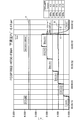
- Table 1 shows the main specifications of the FCSP7002-GT50-F88A type pressure flow control device used in this example.
- the inside of the raw material vapor supply path L 1 is evacuated by the vacuum exhaust pump 16, and then argon gas is introduced from the purge gas supply port 2 and finally exhausted by the vacuum exhaust pump 16.
- the source tank 6, the pressure type flow control device 10, the raw material vapor supply path L 1 and the like are heated and held at 45 ° C. by the constant temperature heating unit 9, and the raw material vapor G ′ (vapor pressure 69. 5 kPaabs.) Is generated. Further, the vacuum exhaust pump 16 holds the pressure P2 ′ of the vacuum pressure gauge 17 at the end of the raw material vapor flow path downstream of the pressure type flow rate control device at a predetermined set value.
- the flow rate setting of the pressure type flow control device 10 is performed in 10% increments over the flow range of 10 to 50% of the full scale flow rate (FS), and the set flow rate and the measured value of the TMGa vapor flow rate are set.
- the flowing gas fluid was TMGa vapor by measuring the absorbance and spectrum analysis of the raw material vapor (TMGa vapor) by FT-IR.
- argon gas is supplied from the dilution gas supply port 3 to dilute the raw material vapor G ′ flowing into the FT-IR. This is because the absorbance cannot be measured by adjusting the sensitivity of FT-IR when it is distributed, and the absorbance of FT-IR can be measured by using a dilution gas.
- FIG. 5 shows the result of the flow rate control characteristic test of Example 1, using the F88A type as the pressure type flow rate control device 10 and setting the set pressure P 2 ′ of the vacuum pressure gauge 17 on the downstream side thereof to 1.0 Torr.
- the temperature ° C (curve A) of the pressure type flow control device 10 the detected pressure Torr (curve B) of the vacuum pressure gauge 17, the set flow rate input signal (curve C) and the flow rate output signal (curve C) of the pressure type flow control device 10 Curve D), which was measured using a data logger.
- the temperature of the pressure type flow control device is a value measured at the leak port portion on the liquid inlet side (primary side).
- the measured flow rate (sccm) of the TMGa vapor flow when the set flow rate signal is 10% to 50% is 4.3 (10%), 8.6 (20%), 12.8 (30%), 17 0.0 (40%) and 21.4 (50%).
- FIG. 6 is' when the and 5 Torr, 7 P 2 'F88A the pressure type flow rate control device 10, a set pressure P 2 of the vacuum pressure gauge 17 when the 10Torr and 8 0 to P 2'.
- Each characteristic curve similar to FIG. 5 in the case of 4 Torr is shown.
- FIG. 14 shows the relationship between the set measurement flow rate and absorbance in the test of FIG. .
- the constant temperature heating unit 9 heats the source tank 6 and the pressure type flow rate control device 10 to the set temperature, thereby causing the generation delay and flow rate of the raw material vapor (TMGa). It was confirmed that the TMGa vapor can be stably supplied to the process chamber while accurately controlling the flow rate of the TMGa vapor to the set flow rate by the pressure type flow rate control device 10 without causing a control delay.
- the present invention can be widely applied not only as a raw material vaporization supply apparatus used in the MOCVD method but also as a gas supply apparatus for supplying a vapor flow of an organometallic material in a semiconductor manufacturing apparatus, a chemical manufacturing apparatus or the like.
Landscapes
- Chemical & Material Sciences (AREA)
- General Chemical & Material Sciences (AREA)
- Chemical Kinetics & Catalysis (AREA)
- Engineering & Computer Science (AREA)
- Materials Engineering (AREA)
- Mechanical Engineering (AREA)
- Metallurgy (AREA)
- Organic Chemistry (AREA)
- Chemical Vapour Deposition (AREA)
Abstract
Priority Applications (3)
| Application Number | Priority Date | Filing Date | Title |
|---|---|---|---|
| CN201280038133.7A CN103718275B (zh) | 2011-08-01 | 2012-06-11 | 原料气化供给装置 |
| KR1020147000646A KR101513517B1 (ko) | 2011-08-01 | 2012-06-11 | 원료 기화 공급 장치 |
| US14/170,953 US20140216339A1 (en) | 2011-08-01 | 2014-02-03 | Raw material vaporizing and supplying apparatus |
Applications Claiming Priority (2)
| Application Number | Priority Date | Filing Date | Title |
|---|---|---|---|
| JP2011-167915 | 2011-08-01 | ||
| JP2011167915A JP5652960B2 (ja) | 2011-08-01 | 2011-08-01 | 原料気化供給装置 |
Related Child Applications (1)
| Application Number | Title | Priority Date | Filing Date |
|---|---|---|---|
| US14/170,953 Continuation-In-Part US20140216339A1 (en) | 2011-08-01 | 2014-02-03 | Raw material vaporizing and supplying apparatus |
Publications (1)
| Publication Number | Publication Date |
|---|---|
| WO2013018265A1 true WO2013018265A1 (fr) | 2013-02-07 |
Family
ID=47628821
Family Applications (1)
| Application Number | Title | Priority Date | Filing Date |
|---|---|---|---|
| PCT/JP2012/003783 Ceased WO2013018265A1 (fr) | 2011-08-01 | 2012-06-11 | Dispositif de gazéification et d'amenée de matière première |
Country Status (6)
| Country | Link |
|---|---|
| US (1) | US20140216339A1 (fr) |
| JP (1) | JP5652960B2 (fr) |
| KR (1) | KR101513517B1 (fr) |
| CN (1) | CN103718275B (fr) |
| TW (1) | TWI481740B (fr) |
| WO (1) | WO2013018265A1 (fr) |
Families Citing this family (19)
| Publication number | Priority date | Publication date | Assignee | Title |
|---|---|---|---|---|
| JP5837869B2 (ja) | 2012-12-06 | 2015-12-24 | 株式会社フジキン | 原料気化供給装置 |
| DE102014115497A1 (de) * | 2014-10-24 | 2016-05-12 | Aixtron Se | Temperierte Gaszuleitung mit an mehreren Stellen eingespeisten Verdünnungsgasströmen |
| JP6442234B2 (ja) * | 2014-11-07 | 2018-12-19 | 株式会社ニューフレアテクノロジー | 気相成長装置、貯留容器および気相成長方法 |
| US10221070B2 (en) | 2015-03-09 | 2019-03-05 | Mitsubishi Heavy Industries Engineering, Ltd. | Coal upgrade plant and method for manufacturing upgraded coal |
| JP6578125B2 (ja) * | 2015-04-30 | 2019-09-18 | 株式会社フジキン | 気化供給装置 |
| EP3162914A1 (fr) * | 2015-11-02 | 2017-05-03 | IMEC vzw | Appareil et procédé de fourniture d'un précurseur gazeux à une chambre de réaction |
| US10087523B2 (en) * | 2016-05-20 | 2018-10-02 | Lam Research Corporation | Vapor delivery method and apparatus for solid and liquid precursors |
| CN109423622B (zh) * | 2017-08-29 | 2020-10-13 | 胜高股份有限公司 | 气体供给装置、气体供给方法 |
| CN109440088A (zh) * | 2018-08-23 | 2019-03-08 | 福莱特玻璃集团股份有限公司 | 一种用于在线镀膜玻璃生产的保温装置 |
| CN111169826A (zh) * | 2018-11-13 | 2020-05-19 | 长鑫存储技术有限公司 | 原料存储罐及半导体设备 |
| KR102446230B1 (ko) * | 2018-12-11 | 2022-09-22 | 주식회사 원익아이피에스 | 기판처리장치 및 이를 이용한 기판처리방법 |
| JP7226222B2 (ja) * | 2019-09-24 | 2023-02-21 | 東京エレクトロン株式会社 | ガス供給装置及びガス供給方法 |
| TWI846960B (zh) * | 2019-10-04 | 2024-07-01 | 法商液態空氣喬治斯克勞帝方法研究開發股份有限公司 | 低揮發性前驅物的供應系統 |
| JP7421318B2 (ja) * | 2019-11-27 | 2024-01-24 | 株式会社堀場エステック | 液体材料気化装置、液体材料気化装置の制御方法、及び、液体材料気化装置用プログラム |
| US11817297B2 (en) * | 2020-03-06 | 2023-11-14 | Applied Materials, Inc. | System and method for managing substrate outgassing |
| CN111560597B (zh) * | 2020-06-18 | 2022-07-01 | 湖南铠欣新材料科技有限公司 | 碳化硅化学气相沉积炉的进气装置 |
| EP4423311A4 (fr) * | 2021-10-27 | 2026-04-22 | Entegris Inc | Système de distribution à pression de vapeur élevée |
| CN114429870B (zh) * | 2022-02-24 | 2023-03-24 | 江苏振华新云电子有限公司 | 一种片式钽电解电容器蒸汽流量稳定输出调节装置 |
| CN114743900A (zh) * | 2022-04-25 | 2022-07-12 | 北京北方华创微电子装备有限公司 | 汽化系统以及半导体工艺设备 |
Citations (4)
| Publication number | Priority date | Publication date | Assignee | Title |
|---|---|---|---|---|
| JP2000282242A (ja) * | 1999-04-01 | 2000-10-10 | Tokyo Electron Ltd | 気化器、処理装置、処理方法、及び半導体チップの製造方法 |
| JP2009059871A (ja) * | 2007-08-31 | 2009-03-19 | Sumitomo Chemical Co Ltd | 有機金属化合物供給容器 |
| JP2009252760A (ja) * | 2008-04-01 | 2009-10-29 | Fujikin Inc | 気化器を備えたガス供給装置 |
| JP2011137235A (ja) * | 1999-12-11 | 2011-07-14 | Sigma Aldrich Co | 有機金属前駆物質を複数のエピタキシャル・リアクター部にバルク供給するための方法 |
Family Cites Families (10)
| Publication number | Priority date | Publication date | Assignee | Title |
|---|---|---|---|---|
| US4393013A (en) * | 1970-05-20 | 1983-07-12 | J. C. Schumacher Company | Vapor mass flow control system |
| US5288325A (en) * | 1991-03-29 | 1994-02-22 | Nec Corporation | Chemical vapor deposition apparatus |
| US5451258A (en) * | 1994-05-11 | 1995-09-19 | Materials Research Corporation | Apparatus and method for improved delivery of vaporized reactant gases to a reaction chamber |
| JP3522535B2 (ja) * | 1998-05-29 | 2004-04-26 | 忠弘 大見 | 圧力式流量制御装置を備えたガス供給設備 |
| US6656282B2 (en) * | 2001-10-11 | 2003-12-02 | Moohan Co., Ltd. | Atomic layer deposition apparatus and process using remote plasma |
| JP4195819B2 (ja) * | 2003-01-17 | 2008-12-17 | 忠弘 大見 | 弗化水素ガスの流量制御方法及びこれに用いる弗化水素ガス用流量制御装置 |
| JP4605790B2 (ja) * | 2006-06-27 | 2011-01-05 | 株式会社フジキン | 原料の気化供給装置及びこれに用いる圧力自動調整装置。 |
| DE102007011589A1 (de) * | 2007-03-08 | 2008-09-11 | Schott Ag | Fördereinrichtung für Precursor |
| US20090214777A1 (en) * | 2008-02-22 | 2009-08-27 | Demetrius Sarigiannis | Multiple ampoule delivery systems |
| JP5562712B2 (ja) * | 2010-04-30 | 2014-07-30 | 東京エレクトロン株式会社 | 半導体製造装置用のガス供給装置 |
-
2011
- 2011-08-01 JP JP2011167915A patent/JP5652960B2/ja active Active
-
2012
- 2012-06-11 KR KR1020147000646A patent/KR101513517B1/ko active Active
- 2012-06-11 CN CN201280038133.7A patent/CN103718275B/zh not_active Expired - Fee Related
- 2012-06-11 WO PCT/JP2012/003783 patent/WO2013018265A1/fr not_active Ceased
- 2012-07-02 TW TW101123716A patent/TWI481740B/zh active
-
2014
- 2014-02-03 US US14/170,953 patent/US20140216339A1/en not_active Abandoned
Patent Citations (4)
| Publication number | Priority date | Publication date | Assignee | Title |
|---|---|---|---|---|
| JP2000282242A (ja) * | 1999-04-01 | 2000-10-10 | Tokyo Electron Ltd | 気化器、処理装置、処理方法、及び半導体チップの製造方法 |
| JP2011137235A (ja) * | 1999-12-11 | 2011-07-14 | Sigma Aldrich Co | 有機金属前駆物質を複数のエピタキシャル・リアクター部にバルク供給するための方法 |
| JP2009059871A (ja) * | 2007-08-31 | 2009-03-19 | Sumitomo Chemical Co Ltd | 有機金属化合物供給容器 |
| JP2009252760A (ja) * | 2008-04-01 | 2009-10-29 | Fujikin Inc | 気化器を備えたガス供給装置 |
Also Published As
| Publication number | Publication date |
|---|---|
| TWI481740B (zh) | 2015-04-21 |
| CN103718275A (zh) | 2014-04-09 |
| KR101513517B1 (ko) | 2015-04-20 |
| KR20140024044A (ko) | 2014-02-27 |
| CN103718275B (zh) | 2016-03-23 |
| JP2013033782A (ja) | 2013-02-14 |
| JP5652960B2 (ja) | 2015-01-14 |
| TW201321547A (zh) | 2013-06-01 |
| US20140216339A1 (en) | 2014-08-07 |
Similar Documents
| Publication | Publication Date | Title |
|---|---|---|
| JP5652960B2 (ja) | 原料気化供給装置 | |
| CN103797563B (zh) | 具备原料浓度检测结构的原料气化供给装置 | |
| TWI525734B (zh) | And a raw material gas supply device for a semiconductor manufacturing apparatus | |
| JP5949586B2 (ja) | 原料ガス供給装置、成膜装置、原料の供給方法及び記憶媒体 | |
| US9994955B2 (en) | Raw material vaporization and supply apparatus | |
| CN101479402B (zh) | 原料的气化供给装置以及用于其的自动压力调节装置 | |
| KR101052156B1 (ko) | 가스 공급 방법 및 가스 공급 장치 | |
| TWI445058B (zh) | A gasification supply device for a raw material | |
| US8776821B2 (en) | Vapor delivery device, methods of manufacture and methods of use thereof | |
| US9416452B2 (en) | Vapor delivery device, methods of manufacture and methods of use thereof | |
| CN101760727A (zh) | 材料气体浓度控制装置 | |
| KR20140097011A (ko) | 원료 가스 공급 장치, 성막 장치, 유량의 측정 방법 및 기억 매체 | |
| US20070292612A1 (en) | Metal-organic vaporizing and feeding apparatus, metal-organic chemical vapor deposition apparatus, metal-organic chemical vapor deposition method, gas flow rate regulator, semiconductor manufacturing apparatus, and semiconductor manufacturing method | |
| KR20050087857A (ko) | 클러스터화하는 유체의 유량제어방법 및 이것에 사용하는클러스터화하는 유체용의 유량제어장치 | |
| JP2012146321A (ja) | 圧力制御式流量基準器を構成する基準圧力式流量制御器用の耐食性圧力式流量制御器。 |
Legal Events
| Date | Code | Title | Description |
|---|---|---|---|
| WWE | Wipo information: entry into national phase |
Ref document number: 201280038133.7 Country of ref document: CN |
|
| 121 | Ep: the epo has been informed by wipo that ep was designated in this application |
Ref document number: 12820215 Country of ref document: EP Kind code of ref document: A1 |
|
| ENP | Entry into the national phase |
Ref document number: 20147000646 Country of ref document: KR Kind code of ref document: A |
|
| NENP | Non-entry into the national phase |
Ref country code: DE |
|
| 122 | Ep: pct application non-entry in european phase |
Ref document number: 12820215 Country of ref document: EP Kind code of ref document: A1 |