WO2013018331A1 - Battery storage block and battery module - Google Patents
Battery storage block and battery module Download PDFInfo
- Publication number
- WO2013018331A1 WO2013018331A1 PCT/JP2012/004778 JP2012004778W WO2013018331A1 WO 2013018331 A1 WO2013018331 A1 WO 2013018331A1 JP 2012004778 W JP2012004778 W JP 2012004778W WO 2013018331 A1 WO2013018331 A1 WO 2013018331A1
- Authority
- WO
- WIPO (PCT)
- Prior art keywords
- block
- battery
- battery storage
- pieces
- storage block
- Prior art date
- Legal status (The legal status is an assumption and is not a legal conclusion. Google has not performed a legal analysis and makes no representation as to the accuracy of the status listed.)
- Ceased
Links
Images




Classifications
-
- H—ELECTRICITY
- H01—ELECTRIC ELEMENTS
- H01M—PROCESSES OR MEANS, e.g. BATTERIES, FOR THE DIRECT CONVERSION OF CHEMICAL ENERGY INTO ELECTRICAL ENERGY
- H01M10/00—Secondary cells; Manufacture thereof
- H01M10/60—Heating or cooling; Temperature control
- H01M10/62—Heating or cooling; Temperature control specially adapted for specific applications
- H01M10/625—Vehicles
-
- H—ELECTRICITY
- H01—ELECTRIC ELEMENTS
- H01M—PROCESSES OR MEANS, e.g. BATTERIES, FOR THE DIRECT CONVERSION OF CHEMICAL ENERGY INTO ELECTRICAL ENERGY
- H01M10/00—Secondary cells; Manufacture thereof
- H01M10/60—Heating or cooling; Temperature control
- H01M10/61—Types of temperature control
- H01M10/613—Cooling or keeping cold
-
- H—ELECTRICITY
- H01—ELECTRIC ELEMENTS
- H01M—PROCESSES OR MEANS, e.g. BATTERIES, FOR THE DIRECT CONVERSION OF CHEMICAL ENERGY INTO ELECTRICAL ENERGY
- H01M10/00—Secondary cells; Manufacture thereof
- H01M10/60—Heating or cooling; Temperature control
- H01M10/64—Heating or cooling; Temperature control characterised by the shape of the cells
- H01M10/643—Cylindrical cells
-
- H—ELECTRICITY
- H01—ELECTRIC ELEMENTS
- H01M—PROCESSES OR MEANS, e.g. BATTERIES, FOR THE DIRECT CONVERSION OF CHEMICAL ENERGY INTO ELECTRICAL ENERGY
- H01M10/00—Secondary cells; Manufacture thereof
- H01M10/60—Heating or cooling; Temperature control
- H01M10/65—Means for temperature control structurally associated with the cells
- H01M10/655—Solid structures for heat exchange or heat conduction
- H01M10/6556—Solid parts with flow channel passages or pipes for heat exchange
- H01M10/6557—Solid parts with flow channel passages or pipes for heat exchange arranged between the cells
-
- H—ELECTRICITY
- H01—ELECTRIC ELEMENTS
- H01M—PROCESSES OR MEANS, e.g. BATTERIES, FOR THE DIRECT CONVERSION OF CHEMICAL ENERGY INTO ELECTRICAL ENERGY
- H01M10/00—Secondary cells; Manufacture thereof
- H01M10/60—Heating or cooling; Temperature control
- H01M10/65—Means for temperature control structurally associated with the cells
- H01M10/656—Means for temperature control structurally associated with the cells characterised by the type of heat-exchange fluid
- H01M10/6561—Gases
-
- H—ELECTRICITY
- H01—ELECTRIC ELEMENTS
- H01M—PROCESSES OR MEANS, e.g. BATTERIES, FOR THE DIRECT CONVERSION OF CHEMICAL ENERGY INTO ELECTRICAL ENERGY
- H01M50/00—Constructional details or processes of manufacture of the non-active parts of electrochemical cells other than fuel cells, e.g. hybrid cells
- H01M50/20—Mountings; Secondary casings or frames; Racks, modules or packs; Suspension devices; Shock absorbers; Transport or carrying devices; Holders
- H01M50/204—Racks, modules or packs for multiple batteries or multiple cells
- H01M50/207—Racks, modules or packs for multiple batteries or multiple cells characterised by their shape
- H01M50/213—Racks, modules or packs for multiple batteries or multiple cells characterised by their shape adapted for cells having curved cross-section, e.g. round or elliptic
-
- H—ELECTRICITY
- H01—ELECTRIC ELEMENTS
- H01M—PROCESSES OR MEANS, e.g. BATTERIES, FOR THE DIRECT CONVERSION OF CHEMICAL ENERGY INTO ELECTRICAL ENERGY
- H01M50/00—Constructional details or processes of manufacture of the non-active parts of electrochemical cells other than fuel cells, e.g. hybrid cells
- H01M50/20—Mountings; Secondary casings or frames; Racks, modules or packs; Suspension devices; Shock absorbers; Transport or carrying devices; Holders
- H01M50/289—Mountings; Secondary casings or frames; Racks, modules or packs; Suspension devices; Shock absorbers; Transport or carrying devices; Holders characterised by spacing elements or positioning means within frames, racks or packs
- H01M50/291—Mountings; Secondary casings or frames; Racks, modules or packs; Suspension devices; Shock absorbers; Transport or carrying devices; Holders characterised by spacing elements or positioning means within frames, racks or packs characterised by their shape
-
- H—ELECTRICITY
- H01—ELECTRIC ELEMENTS
- H01M—PROCESSES OR MEANS, e.g. BATTERIES, FOR THE DIRECT CONVERSION OF CHEMICAL ENERGY INTO ELECTRICAL ENERGY
- H01M50/00—Constructional details or processes of manufacture of the non-active parts of electrochemical cells other than fuel cells, e.g. hybrid cells
- H01M50/50—Current conducting connections for cells or batteries
- H01M50/502—Interconnectors for connecting terminals of adjacent batteries; Interconnectors for connecting cells outside a battery casing
- H01M50/503—Interconnectors for connecting terminals of adjacent batteries; Interconnectors for connecting cells outside a battery casing characterised by the shape of the interconnectors
-
- Y—GENERAL TAGGING OF NEW TECHNOLOGICAL DEVELOPMENTS; GENERAL TAGGING OF CROSS-SECTIONAL TECHNOLOGIES SPANNING OVER SEVERAL SECTIONS OF THE IPC; TECHNICAL SUBJECTS COVERED BY FORMER USPC CROSS-REFERENCE ART COLLECTIONS [XRACs] AND DIGESTS
- Y02—TECHNOLOGIES OR APPLICATIONS FOR MITIGATION OR ADAPTATION AGAINST CLIMATE CHANGE
- Y02E—REDUCTION OF GREENHOUSE GAS [GHG] EMISSIONS, RELATED TO ENERGY GENERATION, TRANSMISSION OR DISTRIBUTION
- Y02E60/00—Enabling technologies; Technologies with a potential or indirect contribution to GHG emissions mitigation
- Y02E60/10—Energy storage using batteries
Definitions
- the thermal runaway preventing wall is disposed across the entire axial direction of the batteries between two adjacent batteries. For this reason, it is difficult to let cooling air flow between two adjacent batteries. Therefore, the battery storage block disclosed in Patent Document 1 has a problem that the heat generated by the battery can not be dissipated efficiently and sufficiently by the cooling air.
- the width W of the gap 15 is about 0.5 to 5 mm, and the length L of the gap 15 (the length corresponding to the axial length of the small diameter portion 13) is It is set to about 30 to 80% of the axial length (battery height).
- the width W of the gap 15 mentioned here means the distance between the outer peripheral surfaces of the adjacent small diameter portions 13.
- the width W and the length L of the gap 15 are not limited to this, and can be changed as appropriate. However, when the length L of the gap 15 is shorter than 30% of the length of the battery 2, the effect of cooling the block piece 10 by the cooling air passing through the gap 15 is reduced.
- each block piece 10 is disposed so as to cover substantially the entire outer periphery of the stored battery 2, so that the battery 2 can be protected individually.
Landscapes
- Chemical & Material Sciences (AREA)
- Chemical Kinetics & Catalysis (AREA)
- Electrochemistry (AREA)
- General Chemical & Material Sciences (AREA)
- Engineering & Computer Science (AREA)
- Manufacturing & Machinery (AREA)
- Battery Mounting, Suspending (AREA)
- Secondary Cells (AREA)
Abstract
Description
本発明は、電池収納ブロック及び電池収納ブロックを備えた電池モジュールに関するものである。 The present invention relates to a battery storage block and a battery module provided with the battery storage block.
従来、例えば電気自動車のモータ駆動電源として用いられる電池モジュールであって、複数の電池を有するものが知られている。この電池モジュールでは、複数の電池が例えば電池収納ブロックに設けられた複数の電池収納部の夫々に収納されるようにして保持される。このような電池モジュールでは、使用時に複数の電池が発熱するため、電池を保護するには放熱させることが好ましい。 Conventionally, for example, a battery module used as a motor drive power supply of an electric vehicle and having a plurality of batteries is known. In this battery module, for example, a plurality of batteries are held so as to be stored in each of a plurality of battery storage portions provided in a battery storage block. In such a battery module, since a plurality of batteries generate heat at the time of use, it is preferable to radiate heat to protect the batteries.
電池収納ブロックにおいて、電池収納部に収納された電池の発熱を放熱できるものは、例えば特許文献1に開示されている。この特許文献1に開示された電池収納ブロックは、複数の電池を2列に並べた状態で収納する複数のブロック片(熱伝導筒)を備えている。ブロック片の一部は熱暴走防止壁として構成されていて、この熱暴走防止壁は、収納された複数の電池のうち、互いに隣接する2つの電池間において、電池の軸方向の全体に設けられている。電池収納ブロックには、熱暴走防止壁を挟んだ両側にブロック片の一部を開口した開口部が設けられている。その開口部から電池の周部の一部を露出させることにより、そこに冷却風を当てることができる。 For example, Patent Document 1 discloses a battery storage block capable of dissipating heat generated by the battery stored in the battery storage portion. The battery storage block disclosed in Patent Document 1 includes a plurality of block pieces (heat transfer cylinders) for storing a plurality of batteries arranged in two rows. A part of the block piece is configured as a thermal runaway prevention wall, and the thermal runaway prevention wall is provided in the entire battery axial direction between two adjacent batteries among the plurality of stored batteries. ing. The battery storage block is provided with an opening in which a part of the block piece is opened on both sides of the thermal runaway prevention wall. By exposing a part of the periphery of the battery from the opening, cooling air can be applied thereto.
上記特許文献1に開示された電池収納ブロックにおいては、隣接する2つの電池間において電池の軸方向の全体に亘って熱暴走防止壁が配設されている。このため、隣接する2つ電池の間に冷却風を通し難い。したがって、上記特許文献1に開示された電池収納ブロックでは、冷却風によって電池の夫々の発熱を効率よく且つ充分に放熱できない、という問題がある。 In the battery storage block disclosed in Patent Document 1, the thermal runaway preventing wall is disposed across the entire axial direction of the batteries between two adjacent batteries. For this reason, it is difficult to let cooling air flow between two adjacent batteries. Therefore, the battery storage block disclosed in Patent Document 1 has a problem that the heat generated by the battery can not be dissipated efficiently and sufficiently by the cooling air.
本発明の目的は、収納された電池の発熱を効率よく且つ充分に放熱できる電池収納ブロック及び電池モジュールを提供することである。 An object of the present invention is to provide a battery storage block and a battery module capable of efficiently and sufficiently dissipating the heat generation of a stored battery.
本発明の一局面に従う電池収納ブロックは、電池を収納する形状に形成された複数のブロック片を備え、前記複数のブロック片は配列され、前記複数のブロック片のうち互いに隣接する2つのブロック片同士が互いに結合されており、前記互いに隣接する2つのブロック片同士の間には、媒体を流通させ得る流通空間が設けられている。 A battery storage block according to one aspect of the present invention includes a plurality of block pieces formed in a shape for storing a battery, the plurality of block pieces being arranged, and two block pieces adjacent to each other among the plurality of block pieces. The two pieces are coupled to each other, and a distribution space through which the medium can be distributed is provided between the two adjacent block pieces.
また、本発明の他の局面に従う電池モジュールは、前記電池収納ブロックと、前記電池収納ブロックに収納された電池と、を備えている。 A battery module according to another aspect of the present invention includes the battery storage block and a battery stored in the battery storage block.
以下、本発明を実施するための形態について、図面を参照しながら詳細に説明する。 Hereinafter, embodiments of the present invention will be described in detail with reference to the drawings.
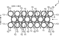
図1(a)は、本発明の一実施形態としての電池収納ブロックを有する電池モジュールの斜視図であり、図1(b)は、前記電池モジュールの分解斜視図である。図2(a)は、前記電池収納ブロックの平面図であり、図2(b)は、前記電池収納ブロックの側面図である。 Fig.1 (a) is a perspective view of the battery module which has a battery storage block as one Embodiment of this invention, FIG.1 (b) is a disassembled perspective view of the said battery module. Fig.2 (a) is a top view of the said battery storage block, FIG.2 (b) is a side view of the said battery storage block.
本実施形態の電池モジュール100は、例えば電気自動車のモータ駆動電源として用いられる。この電池モジュール100は、電池収納ブロック1と、電池収納ブロック1に収納される複数本(本例では20本)の電池2と、正極側ホルダー4と、正極板5と、負極側ホルダー6と、負極板7とを備えている。
The
電池収納ブロック1は、複数(本例では20本)の円筒状のブロック片10を備えている。各ブロック片10は、この実施形態では、アルミニウム又はアルミニウム合金によって構成されている。尚、ブロック片10は、アルミニウム又はアルミニウム合金で構成されるものに限らず、例えば金属、好ましくは放熱性に優れた金属によって構成することができる。
The battery storage block 1 is provided with a plurality of (20 in this example)
各ブロック片10は、軸方向の長さが電池2の軸方向長さと略同じとされており、その内部に電池2を収納するための収納部11を備えている。収納部11の内径は、電池2の外径と略同程度に設定されている。
Each
この実施形態の各ブロック片10は、図2(b)に示すように、凸部としての大径部12と、凹部としての小径部13とを備えている。大径部12は、軸方向の両端にそれぞれ配設され、小径部13は、これら大径部12間に配設されている。小径部13は、大径部12よりも径の小さい断面円形状に形成されている。言い換えると、各ブロック片10においては、軸方向の両端部がそれぞれ凸部となり、両凸部間の部位(小径部13)は、凸部の外周面よりも引っ込んだ外周面を有する凹部として形成されている。言い換えると、大径部12の外面は、小径部13の外面よりも径方向に突出している。なお、大径部12の内周面及び小径部13の内周面は面一の状態となっている。このため、大径部12の肉厚は、小径部13の肉厚よりも大きくなっている。
As shown in FIG. 2B, each
この実施形態では、各ブロック片10は、厚板部12aと薄板部13aとを有する1枚の板状体10aを巻回成形するようにして形成されている。
In this embodiment, each
詳しくは、板状体10aは、図4(a)(b)に示すように、軸方向となる方向(図の上下方向)の両端夫々に配設された厚板部12aと、それらの厚板部12aの間に、厚板部12aよりも板厚の薄い薄板部13aとを備えている。板状体10aの一方の主面(図4(b)の左側の主面)は、平坦な面に形成されている。一方、他方の主面(図4(b)の右側の主面)は、厚板部12aにおいて薄板部13aよりも段差状に突出するように形成されている。
Specifically, as shown in FIGS. 4 (a) and 4 (b), the plate-
そして、板状体10aを、前記一方の主面が内側面となり前記他方の主面が外側面となった状態で断面円形状になるように、図4(a)の左右方向に巻回し、板状体10aの左右の両端部を互いに連結する。このとき、厚板部12aの左右の両端部を互いに連結するとともに薄板部13aの左右の両端部を互いに連結する。このようにして、厚板部12aにより形成された大径部12と薄板部13aにより形成された小径部13とを有するブロック片10が形成されている。
Then, the plate-
複数(この実施形態では、7個又は6個)のブロック片10は、図2(a)(b)に示すように、第1方向(図の左右方向であるX-X方向)に沿って一列に並べられており、第1方向列14を形成している。この状態で、隣接する2つのブロック片10の大径部12同士が対向するとともに、小径部13同士が対向している。また、隣接する2つのブロック片10は、その軸Oが互いに平行になっている。
As shown in FIGS. 2A and 2B, a plurality of (in this embodiment, seven or six)
そのようにして形成された第1方向列14が少なくとも3つ(本実施形態では3つ)形成されていて、これら第1方向列14は、第1方向と交差する第2方向(Y-Y方向)に並ぶように配列されている。本実施形態では、第1方向と第2方向とは直交する関係となっている。
At least three (three in the present embodiment)
本実施形態では、隣接する2つの第1方向列14において、ブロック片10は互い違いに配置されている。すなわち、Y-Y方向に見ると、一方の第1方向列14におけるブロック片10の軸Oが、他方の第1方向列14において隣接する2つのブロック片10の軸Oの間の略中央位置に配置されており、ブロック片10は、いわゆる千鳥配列で配置されている。
In the present embodiment, the
隣接する2つのブロック片10は、互いに連結されている。この連結は、本実施形態では、次のようにして行われている。
Two
上述したように巻回成形されたブロック片10の大径部12の外周面に、ブロック片10よりも融点の低い低融点合金からなる結合材(ロー)16を予め配設しておく。
As described above, a bonding material (row) 16 made of a low melting point alloy having a melting point lower than that of the
そして、図示しない箱体内に20個のブロック片10を上記千鳥配列で配置する。このとき、隣接する2つのブロック片10の大径部12がそれぞれ結合材16に当接するようにセットされる。
Then, 20
この箱体内にセットされた複数のブロック片10を、結合材16が溶融する温度雰囲気に所定時間、保持し、その後、例えば室温に放置する。これにより、隣接する2つのブロック片10が、大径部12において結合材16を介して固定的に結合される。そして、配列された複数のブロック片10が互いに連結されることになる。
The plurality of
隣接する2つのブロック片10が互いに結合された状態で、図2(b)、図3に示すように、互いに隣接するブロック片10の小径部13同士の間に、流通空間としての間隙15が形成されている。すなわち、ブロック片10の外周面のうちの一部(大径部12の外周面)が隣接するブロック片10に結合される一方、この結合された部位以外の部位は、流通空間を形成している。
In the state where two
尚、本実施形態では、間隙15の幅Wは、0.5~5mm程度であり、間隙15の長さL(小径部13の軸方向の長さに相当する長さ)は、電池2の軸方向の長さ(電池の高さ)の30~80%程度に設定されている。ここでいう間隙15の幅Wは、隣り合う小径部13の外周面間の距離を意味している。尚、間隙15の幅W及び長さLは、これに限らず、適宜変更できる。ただし、間隙15の長さLが電池2の長さの30%よりも短くなると、間隙15を通過する冷却風によってブロック片10を冷却する効果が小さくなる。一方、間隙15の長さLが電池2の長さの80%を超えると、ブロック片10が電池2から吸熱した熱を放熱する効率が低下するおそれがある。従って、上述のように、間隙15の長さLは、電池2の長さの30~80%程度が好ましい。
In the present embodiment, the width W of the
また、このようにして形成された流通空間としての間隙15は、全部が連通している。
In addition, the
図1に戻り、本実施形態では、電池2は、直径が約18mm、軸方向の長さが約65mmの円柱体状に形成されている。なお、図1は、上部が正極(+極)、下部が負極(-極)となった状態を示している。
Returning to FIG. 1, in the present embodiment, the
電池2は、正極が上向きで負極が下向きとなるように、電池収納ブロック1の各収納部11にそれぞれ収納される。
The
正極側ホルダー4は、本実施形態では、電池収納ブロック1の一端側(図1の上端側)に取付けられている。なお、電池収納ブロック1への正極側ホルダー4の取付けは、電池2がブロック片10の収納部11に収納された後に行われる。
The positive
負極側ホルダー6は、本実施形態では、電池収納ブロック1の他端側(図1の下端側)に取付けられる。なお、電池収納ブロック1への負極側ホルダー6の取付けは、電池2がブロック片10の収納部11に収納された後に行われる。
The negative
電池収納ブロック1に収納された各電池2は、正極側ホルダー4と負極側ホルダー6によって挟持されている。
Each
正極板5は、各電池2の正極に電気的に接続され、負極板7は、各電池2の負極に電気的に接続されている。
The
このように構成された電池モジュール100は、単独でも使用できるが、他の電池モジュール100と通電可能に接続して使用することもできる。例えば図5に示すように、一方の電池モジュール100の正極板5の第1方向(X-X方向)の端部に接続されたバスバー8を、他方の電池モジュール100の負極板7の第1方向の端部に接続する。これにより、複数の電池モジュール100が直列接続される。例えば、1個の電池モジュール100の出力電圧を4Vとすれば、100個の電池モジュール100を直列接続することにより、400Vの電池モジュールが得られる。この電池モジュールは、自動車等のモータ駆動用電源として使用することができる。
The
尚、電池モジュール100同士の接続は、第1方向の端部同士を接続する形態のものに限らず、適宜変更できる。例えばバスバー8の一端部を、一方の電池モジュール100の正極板5の第2方向(Y-Y方向)の端部に通電可能に接続するとともに、バスバー8の他端部を、他方の電池モジュール100の負極板7の第2方向の端部に通電可能に接続するようにしてもよい。
The connection between the
以上のように構成された電池モジュール100は、自動車等に搭載されてモータ駆動用電源として用いられる。その使用に際して電池2が発熱するが、電池収納ブロック1のブロック片10が金属製であるため、ブロック片10が電池2から吸熱して放熱できる。
The
電池収納ブロック1は、例えば、一端側(図3の右端側)から、図示しない媒体送り装置によって冷却媒体としての冷却風が送り込まれた状態で使用される。これにより、冷却風は、図3中に矢印で示すように電池収納ブロック1に形成された間隙15を順次縫うように流通する。
The battery storage block 1 is used, for example, in a state in which cooling air as a cooling medium is fed by a not-shown medium feeding device from one end side (right end side in FIG. 3). As a result, the cooling air flows so as to sequentially sew the
従って、各ブロック片10の全周をより効率よく冷却でき、しかも充分に放熱できる。
Therefore, the entire circumference of each
各ブロック片10の収納部11は、収納された電池2のほぼ全外周を覆うように配設されているため、電池2を個々に保護することができる。
The
尚、上記実施形態では、ブロック片10が大径部12と小径部13とを有する構成とされているが、この形態に限らず、適宜変更できる。例えば図6に示すように、外径が軸方向の全体に亘って同じであるブロック片210を備えた構成としてもよい。この場合、ブロック片210の軸方向の両端夫々に、予め定められた所定の厚さを有し且つ低融点合金からなる結合材216が配設される。軸方向の一方側の結合材216と他方側の結合材216とは、互いに離間している。そして、上述のようにして、隣接する2つのブロック片210の結合材216同士が結合されることにより、ブロック片210の軸方向の中央部(離間した結合材216の間の部位)に、両結合材216の厚さ分の間隙215が形成されている。このようにして構成された電池収納ブロック201においても、互いに隣接するブロック片210が、結合材216を介して互いに結合される一方で、結合された部位以外の部位に間隙215が形成された構成となる。
Although the
また上記実施形態では、ブロック片10,210同士の結合が、結合材16,216を用いたロー付けにより行われているが、ブロック片同士を連結するための結合手段は特に限定されない。例えばブロック片同士を、接着剤による連結としたり、溶接による連結としてもよく、適宜変更できる。溶接による連結の場合、例えば、レーザ溶接による連結とすることができる。
Moreover, in the said embodiment, although coupling | bonding of
ここで、複数のブロック片10が連結された構成の電池収納ブロック1の製造方法の一例について、図7(a)から(d)を参照しつつ説明する。この製造方法は、隣接するブロック片10をレーザ溶接によって接合する場合の製造方法の一例であり、図7(d)に示すように、3つの第1方向列14が形成された電池収納ブロック1を製造する場合を例示している。
Here, an example of a method of manufacturing the battery storage block 1 having a configuration in which a plurality of
電池収納ブロック1を製造するには、まず、第1方向列14の数に等しい数(ここでは、3つ)のブロック片10を用意し、これらブロック片10が互いに接触した状態で一列に並べる。そして、この状態で、隣接ブロック片10同士をレーザ溶接する。これにより、3つのブロック片10が連結された一列パイプ22となる(図7(a)(b))。
In order to manufacture the battery storage block 1, first, a number (here, three) of
次に、図7(c)に示すように、複数(ここでは6つ)の一列パイプ22と、複数(ここでは2つ)の単品パイプ(ブロック片10)24を用い、ブロック片10が千鳥配列となり、かつ隣り合う一列パイプ22が互いに接触するように、複数の一列パイプ22を第1方向に並べる。この状態では、第1方向に対して斜めの方向に隣り合う3つのブロック片10が連結された状態にある一方で、第1方向に隣り合うブロック片10同士は未だ連結されていない。
Next, as shown in FIG. 7C, a plurality of (here, six) single-
そして、この並べられた複数のブロック片10において、対向する一対の角部にそれぞれ単品パイプ(ブロック片10)24を配置する。このように、電池収納ブロック1を構成する全てのブロック片10が配置されたところで、図7(d)に示すように、隣接ブロック片10間をレーザ溶接する。すなわち、隣接する一列パイプ22同士をレーザ溶接によって接合するとともに、端に位置する一列パイプ22と単品パイプ24とをレーザ溶接によって接合する。これにより、全てのブロック片10のそれぞれがその隣のブロック片10に固着された状態となる。
Then, in the plurality of arranged
なお、第1方向列14に並ぶブロック片10の数が異なるものに対しては、それに応じた数の一列パイプ22を使用すればよい。また、第2方向に並ぶブロック片10の数が3以外の場合には、一列パイプ22を構成するブロック片10の数をそれに応じて変えればよい。
If the number of
また上記実施形態では、全てのブロック片10が大径部12と小径部13とを有する構成とされているが、この形態に限らず、適宜変更できる。例えば、隣接する2つのブロック片の内の何れか一方のブロック片が、大径部と小径部とを有し、他方のブロック片が、外径が軸方向の全長に渡って同じ構成であってもよい。
Moreover, in the said embodiment, although all the
また上記実施形態では、間隙を全て同じ寸法とし、かつ全ての間隙がブロック片10の軸方向における同じ位置に設けられる構成としたが、この形態に限らず、適宜変更できる。例えば間隙のうちの1つ又は複数を、他の間隙と異なる寸法としてもよく、あるいは、間隙のうちの1つ又は複数を、他の間隙とブロック片10の軸方向における異なる位置に設けてもよい。
In the above embodiment, all the gaps have the same size, and all the gaps are provided at the same position in the axial direction of the
ただし、電池は、軸方向の両端よりも中央部からの発熱量が多いので、上記実施形態のように、ブロック片10の軸方向における中央部に間隙が配設されることが好ましい。
However, since the battery generates more heat from the central portion than both ends in the axial direction, it is preferable that a gap be provided at the central portion in the axial direction of the
また上記実施形態では、電池収納ブロック1が3つの第1方向列14を有する構成としたが、この形態に限られない。例えば、電池収納ブロック1が、1つ、2つ又は4つ以上の第1方向列14を有する構成としてもよい。
Moreover, in the said embodiment, although the battery storage block 1 was set as the structure which has three 1st direction row | line |
また上記実施形態では、隣接する2つの第1方向列14が千鳥配列で配置される構成としたが、この形態に限られない。例えば、隣接する2つの第1方向列14のうちの一方の列におけるブロック片10の軸Oと、他方の列におけるブロック片10の軸Oとが、第2方向に並ぶように配置されてもよい。
In the above embodiment, two adjacent
また上記実施形態では、ブロック片10,210が円筒状に構成されているが、この形態に限られない。例えば、ブロック片は、外周形状が多角形状の筒状に形成されていてもよい。
Moreover, in the said embodiment, although the
また上記実施形態では、ブロック片10,210を冷却する媒体として気体(冷却風)が流通空間に流れる構成としたが、この形態に限られない。例えば、液体の冷却媒体が流通空間に流通する構成としてもよい。 Moreover, in the said embodiment, although it was set as the structure which gas (cooling air) flows into distribution space as a medium which cools block piece 10,210, it is not restricted to this form. For example, a liquid cooling medium may be circulated in the circulation space.
電池モジュールは、電気自動車のモータ駆動源として用いられるものに限らず、種々の機器の駆動源として用いることができる。 The battery module is not limited to one used as a motor drive source of an electric vehicle, and can be used as a drive source of various devices.
ここで、前記実施形態について概説する。 Here, the embodiment will be outlined.
(1) 前記実施形態の電池収納ブロックは、電池を収納する形状に形成された複数のブロック片を備え、前記複数のブロック片は配列され、前記複数のブロック片のうち互いに隣接する2つのブロック片同士が互いに結合されており、前記互いに隣接する2つのブロック片同士の間には、媒体を流通させ得る流通空間が設けられている。 (1) The battery storage block of the embodiment includes a plurality of block pieces formed in a shape for storing a battery, and the plurality of block pieces are arranged, and two blocks adjacent to each other among the plurality of block pieces The pieces are coupled to each other, and a distribution space through which the medium can be distributed is provided between the two adjacent block pieces.
この電池収納ブロックでは、配列された複数のブロック片のうち、隣接する2つのブロック片同士の間に、媒体を流通させ得る流通空間が設けられている。このため、媒体としての例えば冷却風を流通空間の一端側から流通空間内に送り込むことにより、冷却風を各流通空間に流通させることができる。これにより、各ブロック片の外周を周方向の略全体に亘って冷却できる。したがって、電池の発熱を効率よく、しかも充分に放熱できる。 In the battery storage block, a distribution space through which the medium can be distributed is provided between two adjacent block pieces among the arranged block pieces. For this reason, cooling air can be distributed to each distribution space by sending, for example, cooling air as a medium into the distribution space from one end side of the distribution space. Thereby, the outer periphery of each block piece can be cooled over substantially the entire circumferential direction. Therefore, the heat generated by the battery can be dissipated efficiently and sufficiently.
(2) 前記互いに隣接する2つのブロック片の少なくとも一方は、凸部と、前記凸部の外周面よりも引っ込んだ外周面を有する凹部とを備えていてもよく、この場合において、前記凸部は、前記互いに隣接する2つのブロック片の他方に結合され、前記凹部と前記他方のブロック片との間には、前記流通空間としての間隙が形成されていてもよい。 (2) At least one of the two block pieces adjacent to each other may include a protrusion and a recess having an outer peripheral surface recessed from an outer peripheral surface of the protrusion. In this case, the protrusion May be coupled to the other of the two adjacent block pieces, and a gap as the communication space may be formed between the recess and the other block piece.
この態様では、外周に凸部と凹部とを有するブロック片が用いられ、互いに隣接する一方のブロック片の凸部が他方のブロック片に連結されている。したがって、一方のブロック片の凹部と他方のブロックとによってそれらの間に、容易に、しかも確実に流通空間としての間隙を形成できる。従って、流通空間を有する電池収納ブロックを容易に形成できる。 In this aspect, a block piece having a convex portion and a concave portion on the outer periphery is used, and the convex portion of one block piece adjacent to each other is connected to the other block piece. Therefore, the recess of one block piece and the other block can form a gap as a flow space easily and reliably between them. Therefore, the battery storage block having the flow space can be easily formed.
(3) 前記互いに隣接する2つのブロック片の少なくとも一方は、円筒状に形成されるとともに、大径部と、前記大径部よりも径の小さい小径部とを備えていてもよく、この場合には、前記大径部は、前記互いに隣接する2つのブロック片の他方に結合され、前記小径部と前記他方のブロック片との間には、前記流通空間としての間隙が形成されていてもよい。 (3) At least one of the two adjacent block pieces may be formed in a cylindrical shape, and may have a large diameter portion and a small diameter portion smaller in diameter than the large diameter portion, in this case The large diameter portion is coupled to the other of the two adjacent block pieces, and a gap as the flow space is formed between the small diameter portion and the other block piece. Good.
この態様では、大径部と小径部とを備えたブロック片が用いられ、隣接する一方のブロック片の大径部が他方のブロック片に連結されている。したがって、一方のブロック片の小径部と他方のブロックとによって、それらの間に、容易に、しかも確実に流通空間としての間隙を区画形成できる。従って、流通空間を有する電池収納ブロックを、容易に形成することができる。 In this aspect, a block piece having a large diameter portion and a small diameter portion is used, and the large diameter portion of one adjacent block piece is connected to the other block piece. Therefore, the small diameter portion of one block piece and the other block can easily and surely define a gap as a circulation space between them. Therefore, the battery storage block having the flow space can be easily formed.
(4) 前記流通空間は、前記ブロック片の軸方向の中央部に配設されていてもよい。電池の発熱は、軸方向の両端よりも中央部の方が多い。流通空間がブロック片の軸方向の中央部に配設される構成とすることにより、電池の発熱を、より効率よく冷却できる。 (4) The distribution space may be disposed at the axial center of the block piece. The heat generated by the battery is greater at the central portion than at both axial ends. With the configuration in which the flow space is disposed at the axial center of the block piece, the heat generation of the battery can be cooled more efficiently.
(5) 前記流通空間における前記ブロック片の軸方向に沿う長さは、前記電池の高さの30~80%であってもよい。 (5) The length along the axial direction of the block piece in the circulation space may be 30 to 80% of the height of the battery.
この態様によれば、ブロック片を、より一層、効率よく冷却できるとともに、電池から吸熱したブロック片の熱を、効率よく、しかも充分に放熱できる。 According to this aspect, the block piece can be cooled more efficiently, and the heat of the block piece absorbed from the battery can be dissipated efficiently and sufficiently.
(6) 複数のブロック片が第1方向に沿って一列状に並設された第1方向列が、少なくとも3つ形成されていてもよく、この場合には、前記少なくとも3つの第1方向列は、前記第1方向と交差する第2方向に沿って並設され、隣接する2つの第1方向列のうちの一方におけるブロック片と、他方におけるブロック片とは、互い違いに配置されていてもよい。 (6) At least three first direction rows in which a plurality of block pieces are juxtaposed in a line along the first direction may be formed. In this case, the at least three first direction rows And the block pieces in one of the two adjacent first direction rows and the block pieces in the other are alternately arranged along the second direction intersecting the first direction. Good.
この態様では、隣接する2つの第1方向列同士間の隙間を小さくすることができる。従って、電池収納ブロックの第2方向の長さを短くでき、電池収納ブロックをコンパクトなものにできる。また、隣接する2つの第1方向列のブロック片同士の間に形成された流通空間によって、隣接する2つの第1方向列同士間の隙間が小さくなったとしても、各ブロック片の外周を略全周にわたって冷却できるため、電池の発熱を効率よく、しかも充分に放熱できる。 In this aspect, the gap between two adjacent first direction rows can be reduced. Therefore, the length in the second direction of the battery storage block can be shortened, and the battery storage block can be made compact. In addition, even if the gap between the two adjacent first direction rows is reduced by the circulation space formed between the two adjacent first direction row block pieces, the outer periphery of each block piece is substantially formed. Since the entire circumference can be cooled, the heat of the battery can be dissipated efficiently and sufficiently.
(7) 本実施形態の電池モジュールは、上述した電池収納ブロックと、前記電池収納ブロックに収納された電池とを備えている。 (7) The battery module of the present embodiment includes the battery storage block described above and the battery stored in the battery storage block.
この電池モジュールでは、隣接する2つのブロック片同士の間に形成された流通空間に、媒体としての例えば冷却風を一端側から送ることにより、冷却風を各流通空間に流通させることができる。これにより、ブロック片の電池収納部の周方向の略全体を冷却でき、電池の発熱を効率よく、しかも充分に放熱できる。 In this battery module, the cooling air can be circulated in each of the circulation spaces by sending, for example, a cooling air as a medium from one end side to the circulation space formed between the two adjacent block pieces. As a result, substantially the entire circumferential direction of the battery storage portion of the block piece can be cooled, and heat generation of the battery can be dissipated efficiently and sufficiently.
電池収納ブロック及び電池収納ブロックを備えた電池モジュールに有用である。 It is useful for the battery module provided with the battery storage block and the battery storage block.
1 電池収納ブロック
2 電池
4 正極側ホルダー
5 正極板
6 負極側ホルダー
7 負極板
10 ブロック片
11 電池収納部
12 大径部(凸部)
13 小径部(凹部)
15 間隙(流通空間)
100 電池モジュール
DESCRIPTION OF SYMBOLS 1
13 Small diameter part (concave part)
15 gap (distribution space)
100 battery module
Claims (7)
前記複数のブロック片は配列され、前記複数のブロック片のうち互いに隣接する2つのブロック片同士が互いに結合されており、
前記互いに隣接する2つのブロック片同士の間には、媒体を流通させ得る流通空間が設けられている電池収納ブロック。 A plurality of block pieces formed in a shape for storing the battery;
The plurality of block pieces are arranged, and two adjacent block pieces of the plurality of block pieces are coupled to each other,
The battery storage block in which the distribution space which can distribute | circulate a medium is provided between the two adjacent block pieces.
前記互いに隣接する2つのブロック片の少なくとも一方は、凸部と、前記凸部の外周面よりも引っ込んだ外周面を有する凹部とを備え、
前記凸部は、前記互いに隣接する2つのブロック片の他方に結合され、
前記凹部と前記他方のブロック片との間には、前記流通空間としての間隙が形成されている電池収納ブロック。 In the battery storage block according to claim 1,
At least one of the two adjacent block pieces includes a convex portion and a concave portion having an outer peripheral surface recessed from an outer peripheral surface of the convex portion,
The convex portion is coupled to the other of the two adjacent block pieces,
The battery storage block in which the space | interval as said distribution space is formed between the said recessed part and the said other block piece.
前記互いに隣接する2つのブロック片の少なくとも一方は、円筒状に形成されるとともに、大径部と、前記大径部よりも径の小さい小径部とを備え、
前記大径部は、前記互いに隣接する2つのブロック片の他方に結合され、
前記小径部と前記他方のブロック片との間には、前記流通空間としての間隙が形成されている電池収納ブロック。 In the battery storage block according to claim 1 or 2,
At least one of the two adjacent block pieces is formed in a cylindrical shape, and includes a large diameter portion and a small diameter portion smaller in diameter than the large diameter portion.
The large diameter portion is coupled to the other of the two adjacent block pieces,
A battery storage block in which a gap as the circulation space is formed between the small diameter portion and the other block piece.
前記流通空間は、前記ブロック片の軸方向の中央部に配設されている電池収納ブロック。 The battery storage block according to any one of claims 1 to 3
The battery storage block, wherein the flow space is disposed at an axial center of the block piece.
前記流通空間における前記ブロック片の軸方向に沿う長さは、前記電池の長さの30~80%である電池収納ブロック。 In the battery storage block according to claim 4,
A battery storage block, wherein an axial length of the block piece in the circulation space is 30 to 80% of a length of the battery.
複数のブロック片が第1方向に沿って一列状に並設された第1方向列が、少なくとも3つ形成されており、
前記少なくとも3つの第1方向列は、前記第1方向と交差する第2方向に沿って並設され、
隣接する2つの第1方向列のうちの一方におけるブロック片と、他方におけるブロック片とは、互い違いに配置されている電池収納ブロック。 The battery storage block according to any one of claims 1 to 5,
At least three first direction rows in which a plurality of block pieces are arranged in a line along the first direction are formed;
The at least three first direction rows are juxtaposed along a second direction intersecting the first direction,
The battery storage block by which the block piece in one of two adjacent 1st direction row | lines and the block piece in the other are arrange | positioned alternately.
前記電池収納ブロックに収納された電池と、を備えた電池モジュール。 A battery storage block according to any one of claims 1 to 6;
And a battery stored in the battery storage block.
Priority Applications (3)
| Application Number | Priority Date | Filing Date | Title |
|---|---|---|---|
| EP12819248.1A EP2738833B1 (en) | 2011-07-29 | 2012-07-26 | Battery retainment block and battery module |
| JP2013526746A JP6004349B2 (en) | 2011-07-29 | 2012-07-26 | Battery storage block and battery module |
| US14/233,144 US9246147B2 (en) | 2011-07-29 | 2012-07-26 | Battery retainment block and battery module |
Applications Claiming Priority (2)
| Application Number | Priority Date | Filing Date | Title |
|---|---|---|---|
| JP2011-166588 | 2011-07-29 | ||
| JP2011166588 | 2011-07-29 |
Publications (1)
| Publication Number | Publication Date |
|---|---|
| WO2013018331A1 true WO2013018331A1 (en) | 2013-02-07 |
Family
ID=47628882
Family Applications (1)
| Application Number | Title | Priority Date | Filing Date |
|---|---|---|---|
| PCT/JP2012/004778 Ceased WO2013018331A1 (en) | 2011-07-29 | 2012-07-26 | Battery storage block and battery module |
Country Status (4)
| Country | Link |
|---|---|
| US (1) | US9246147B2 (en) |
| EP (1) | EP2738833B1 (en) |
| JP (1) | JP6004349B2 (en) |
| WO (1) | WO2013018331A1 (en) |
Cited By (7)
| Publication number | Priority date | Publication date | Assignee | Title |
|---|---|---|---|---|
| JP2015122145A (en) * | 2013-12-20 | 2015-07-02 | 豊田合成株式会社 | Battery pack |
| CN106463670A (en) * | 2014-04-07 | 2017-02-22 | 罗伯特·博世有限公司 | Energy storage units, especially battery modules and energy storage systems with many energy storage units |
| JP2017536658A (en) * | 2014-12-16 | 2017-12-07 | アンホイ・シーネン・テクノロジー・カンパニー・リミテッドAnhui Xinen Technology Co., Ltd. | Vehicle battery module with cooling and safety functions |
| US10008752B1 (en) | 2016-12-23 | 2018-06-26 | Anhui Xinen Technology Co., Ltd. | Safety feature for energy storage device |
| US10170735B2 (en) * | 2013-11-12 | 2019-01-01 | Samsung Sdi Co., Ltd. | Battery pack |
| JP2022526294A (en) * | 2019-03-26 | 2022-05-24 | ライファイゼンランデスバンク・オーバーエスターライヒ・アクチエンゲゼルシャフト | Battery module |
| EP3063834B1 (en) * | 2013-10-28 | 2022-10-19 | TE Connectivity Germany GmbH | Connector for connecting cellular electrical elements |
Families Citing this family (19)
| Publication number | Priority date | Publication date | Assignee | Title |
|---|---|---|---|---|
| US10020534B2 (en) | 2014-09-26 | 2018-07-10 | Johnson Controls Technology Company | Free floating battery cell assembly techniques for lithium ion battery module |
| US10103367B2 (en) | 2014-09-26 | 2018-10-16 | Johnson Controls Technology Company | Lithium ion battery module with free floating prismatic battery cells |
| US11108100B2 (en) | 2015-06-30 | 2021-08-31 | Faraday & Future Inc. | Battery module for vehicle energy-storage systems |
| US20170005303A1 (en) | 2015-06-30 | 2017-01-05 | Faraday&Future Inc. | Vehicle Energy-Storage System |
| US9692096B2 (en) | 2015-06-30 | 2017-06-27 | Faraday&Future Inc. | Partially-submerged battery cells for vehicle energy-storage systems |
| US9692095B2 (en) | 2015-06-30 | 2017-06-27 | Faraday&Future Inc. | Fully-submerged battery cells for vehicle energy-storage systems |
| US10826042B2 (en) | 2015-06-30 | 2020-11-03 | Faraday & Future Inc. | Current carrier for vehicle energy-storage systems |
| US11258104B2 (en) | 2015-06-30 | 2022-02-22 | Faraday & Future Inc. | Vehicle energy-storage systems |
| US10505163B2 (en) | 2015-06-30 | 2019-12-10 | Faraday & Future Inc. | Heat exchanger for vehicle energy-storage systems |
| US9995535B2 (en) | 2015-06-30 | 2018-06-12 | Faraday&Future Inc. | Heat pipe for vehicle energy-storage systems |
| JP6256439B2 (en) * | 2015-09-15 | 2018-01-10 | 株式会社デンソー | Battery pack |
| DE102016104165A1 (en) * | 2016-03-08 | 2017-09-14 | Dr. Ing. H.C. F. Porsche Aktiengesellschaft | Module for a traction battery and corresponding traction battery |
| JP6893313B2 (en) * | 2016-06-29 | 2021-06-23 | パナソニックIpマネジメント株式会社 | Battery module |
| KR20180083813A (en) | 2017-01-13 | 2018-07-23 | 주식회사 엘지화학 | Battery Cell Tray Having Volatile Corrosion Inhibitor |
| WO2020186200A1 (en) | 2019-03-14 | 2020-09-17 | Generac Power Systems, Inc. | Battery module thermal management |
| KR102828349B1 (en) * | 2019-09-09 | 2025-07-03 | 삼성에스디아이 주식회사 | Battery pack |
| KR102828348B1 (en) * | 2019-09-09 | 2025-07-03 | 삼성에스디아이 주식회사 | Battery pack |
| DE102021123311A1 (en) | 2021-09-09 | 2023-03-09 | Audi Aktiengesellschaft | Energy store for a motor vehicle and method for producing and dismantling an energy store |
| DE102022128444A1 (en) * | 2022-10-27 | 2024-05-02 | Bayerische Motoren Werke Aktiengesellschaft | Electrical energy storage device and motor vehicle |
Citations (5)
| Publication number | Priority date | Publication date | Assignee | Title |
|---|---|---|---|---|
| JPH02500396A (en) * | 1987-07-03 | 1990-02-08 | クローライド サイレント パワー リミテッド | battery |
| JPH0590816U (en) * | 1992-05-22 | 1993-12-10 | 三洋電機株式会社 | Battery pack |
| JP2005285455A (en) * | 2004-03-29 | 2005-10-13 | Sanyo Electric Co Ltd | Power supply apparatus |
| JP2007066773A (en) | 2005-08-31 | 2007-03-15 | Sanyo Electric Co Ltd | Assembled battery |
| JP2011076841A (en) * | 2009-09-30 | 2011-04-14 | Hitachi Ltd | Battery module |
Family Cites Families (7)
| Publication number | Priority date | Publication date | Assignee | Title |
|---|---|---|---|---|
| JP4631118B2 (en) * | 1999-02-15 | 2011-02-16 | ソニー株式会社 | Battery device for moving body |
| JP4079572B2 (en) * | 2000-04-14 | 2008-04-23 | 松下電器産業株式会社 | Battery pack |
| JP4892788B2 (en) * | 2001-04-23 | 2012-03-07 | トヨタ自動車株式会社 | Battery module |
| WO2008153602A1 (en) * | 2007-03-01 | 2008-12-18 | Johnson Controls-Saft Advanced Power Solutions Llc | Battery module |
| DE102007021309A1 (en) * | 2007-05-07 | 2008-11-13 | Valeo Klimasysteme Gmbh | Drive battery assembly of an electric, fuel cell or hybrid vehicle |
| JP2009211908A (en) * | 2008-03-04 | 2009-09-17 | Panasonic Corp | Battery and battery pack using the same |
| DE102008031175A1 (en) * | 2008-07-03 | 2010-01-07 | Johnson Controls Hybrid And Recycling Gmbh | Rundzellenakkumulator |
-
2012
- 2012-07-26 WO PCT/JP2012/004778 patent/WO2013018331A1/en not_active Ceased
- 2012-07-26 US US14/233,144 patent/US9246147B2/en active Active
- 2012-07-26 EP EP12819248.1A patent/EP2738833B1/en active Active
- 2012-07-26 JP JP2013526746A patent/JP6004349B2/en active Active
Patent Citations (5)
| Publication number | Priority date | Publication date | Assignee | Title |
|---|---|---|---|---|
| JPH02500396A (en) * | 1987-07-03 | 1990-02-08 | クローライド サイレント パワー リミテッド | battery |
| JPH0590816U (en) * | 1992-05-22 | 1993-12-10 | 三洋電機株式会社 | Battery pack |
| JP2005285455A (en) * | 2004-03-29 | 2005-10-13 | Sanyo Electric Co Ltd | Power supply apparatus |
| JP2007066773A (en) | 2005-08-31 | 2007-03-15 | Sanyo Electric Co Ltd | Assembled battery |
| JP2011076841A (en) * | 2009-09-30 | 2011-04-14 | Hitachi Ltd | Battery module |
Non-Patent Citations (1)
| Title |
|---|
| See also references of EP2738833A4 |
Cited By (10)
| Publication number | Priority date | Publication date | Assignee | Title |
|---|---|---|---|---|
| EP3063834B1 (en) * | 2013-10-28 | 2022-10-19 | TE Connectivity Germany GmbH | Connector for connecting cellular electrical elements |
| US10170735B2 (en) * | 2013-11-12 | 2019-01-01 | Samsung Sdi Co., Ltd. | Battery pack |
| JP2015122145A (en) * | 2013-12-20 | 2015-07-02 | 豊田合成株式会社 | Battery pack |
| CN106463670A (en) * | 2014-04-07 | 2017-02-22 | 罗伯特·博世有限公司 | Energy storage units, especially battery modules and energy storage systems with many energy storage units |
| CN106463670B (en) * | 2014-04-07 | 2019-11-08 | 罗伯特·博世有限公司 | Energy storage units, especially battery modules and energy storage systems with many energy storage units |
| US11050106B2 (en) | 2014-04-07 | 2021-06-29 | Robert Bosch Gmbh | Energy storage unit, particularly a battery module, and an energy storage system comprising a plurality of energy storage unit |
| JP2017536658A (en) * | 2014-12-16 | 2017-12-07 | アンホイ・シーネン・テクノロジー・カンパニー・リミテッドAnhui Xinen Technology Co., Ltd. | Vehicle battery module with cooling and safety functions |
| US10008752B1 (en) | 2016-12-23 | 2018-06-26 | Anhui Xinen Technology Co., Ltd. | Safety feature for energy storage device |
| JP2022526294A (en) * | 2019-03-26 | 2022-05-24 | ライファイゼンランデスバンク・オーバーエスターライヒ・アクチエンゲゼルシャフト | Battery module |
| JP7495946B2 (en) | 2019-03-26 | 2024-06-05 | ジョン・ディア・エレクトリク・パワートレイン・リミテッド・ライアビリティ・カンパニー | Battery Module |
Also Published As
| Publication number | Publication date |
|---|---|
| JP6004349B2 (en) | 2016-10-05 |
| US20140154545A1 (en) | 2014-06-05 |
| US9246147B2 (en) | 2016-01-26 |
| EP2738833A4 (en) | 2014-12-31 |
| JPWO2013018331A1 (en) | 2015-03-05 |
| EP2738833B1 (en) | 2018-09-05 |
| EP2738833A1 (en) | 2014-06-04 |
Similar Documents
| Publication | Publication Date | Title |
|---|---|---|
| JP6004349B2 (en) | Battery storage block and battery module | |
| CN104064701B (en) | Electrical storage device and accumulator unit | |
| JP6459207B2 (en) | Power storage device | |
| JP5899420B2 (en) | Battery module | |
| EP3002802B1 (en) | Energy storage module and system | |
| JP6685001B2 (en) | Battery pack | |
| JP2008541386A (en) | Method and apparatus for installing, cooling, connecting and protecting batteries | |
| JP7366449B2 (en) | Battery pack and device including the battery pack | |
| CN103959506A (en) | Power storage device, vehicle | |
| JP2012174496A (en) | Battery module | |
| WO2017002325A1 (en) | Power source device | |
| JP6001078B2 (en) | Battery module | |
| JP2012134101A (en) | Battery module and battery pack | |
| JP5822135B2 (en) | Power storage device | |
| JP2006156404A (en) | Secondary battery module | |
| JP7127586B2 (en) | Battery pack and power storage system | |
| KR102622141B1 (en) | Submodule for high voltage battery | |
| JP7177791B2 (en) | Batteries and electric devices | |
| JP7532788B2 (en) | Battery Module | |
| JP5914193B2 (en) | Battery module | |
| JP5583920B2 (en) | Battery stack cooling structure | |
| JP2012186341A (en) | Power storage device | |
| CN118431609B (en) | Battery module, module comprising annular battery and electric equipment | |
| JP6353942B2 (en) | Power storage device and power storage device unit | |
| WO2025050430A1 (en) | Battery module, module comprising annular battery, and electric device |
Legal Events
| Date | Code | Title | Description |
|---|---|---|---|
| 121 | Ep: the epo has been informed by wipo that ep was designated in this application |
Ref document number: 12819248 Country of ref document: EP Kind code of ref document: A1 |
|
| ENP | Entry into the national phase |
Ref document number: 2013526746 Country of ref document: JP Kind code of ref document: A |
|
| WWE | Wipo information: entry into national phase |
Ref document number: 14233144 Country of ref document: US |
|
| NENP | Non-entry into the national phase |
Ref country code: DE |