WO2013018337A1 - Système de réseau, dispositif de réseau et procédé de contrôle de réseau - Google Patents
Système de réseau, dispositif de réseau et procédé de contrôle de réseau Download PDFInfo
- Publication number
- WO2013018337A1 WO2013018337A1 PCT/JP2012/004797 JP2012004797W WO2013018337A1 WO 2013018337 A1 WO2013018337 A1 WO 2013018337A1 JP 2012004797 W JP2012004797 W JP 2012004797W WO 2013018337 A1 WO2013018337 A1 WO 2013018337A1
- Authority
- WO
- WIPO (PCT)
- Prior art keywords
- standby
- channel
- frequency
- transceivers
- network device
- Prior art date
- Legal status (The legal status is an assumption and is not a legal conclusion. Google has not performed a legal analysis and makes no representation as to the accuracy of the status listed.)
- Ceased
Links
Images






Classifications
-
- H—ELECTRICITY
- H04—ELECTRIC COMMUNICATION TECHNIQUE
- H04J—MULTIPLEX COMMUNICATION
- H04J14/00—Optical multiplex systems
- H04J14/02—Wavelength-division multiplex systems
- H04J14/0227—Operation, administration, maintenance or provisioning [OAMP] of WDM networks, e.g. media access, routing or wavelength allocation
-
- H—ELECTRICITY
- H04—ELECTRIC COMMUNICATION TECHNIQUE
- H04B—TRANSMISSION
- H04B10/00—Transmission systems employing electromagnetic waves other than radio-waves, e.g. infrared, visible or ultraviolet light, or employing corpuscular radiation, e.g. quantum communication
- H04B10/07—Arrangements for monitoring or testing transmission systems; Arrangements for fault measurement of transmission systems
-
- H—ELECTRICITY
- H04—ELECTRIC COMMUNICATION TECHNIQUE
- H04J—MULTIPLEX COMMUNICATION
- H04J14/00—Optical multiplex systems
- H04J14/02—Wavelength-division multiplex systems
- H04J14/0227—Operation, administration, maintenance or provisioning [OAMP] of WDM networks, e.g. media access, routing or wavelength allocation
- H04J14/0254—Optical medium access
- H04J14/0256—Optical medium access at the optical channel layer
- H04J14/0257—Wavelength assignment algorithms
-
- H—ELECTRICITY
- H04—ELECTRIC COMMUNICATION TECHNIQUE
- H04J—MULTIPLEX COMMUNICATION
- H04J14/00—Optical multiplex systems
- H04J14/02—Wavelength-division multiplex systems
- H04J14/0227—Operation, administration, maintenance or provisioning [OAMP] of WDM networks, e.g. media access, routing or wavelength allocation
- H04J14/0254—Optical medium access
- H04J14/0267—Optical signaling or routing
- H04J14/0269—Optical signaling or routing using tables for routing
Definitions
- the present invention relates to a network system, a network device, and a network control method, and more particularly, to a network system, a network device, and a network control method for setting a path using wavelength multiplexing technology.
- the optical communication network is a high-density wavelength multiplexing technology (Dense Wavelength Division) that enables point-to-point (P2P) large-capacity connection in response to the future increase in communication volume and the sophistication of networks due to the diversification of services.
- Multiplexing DWDM
- OXC optical cross-connects
- WSS wavelength selection switches
- multi-path 3 or more
- Non-Patent Document 1 a transceiver aggregator in which a plurality of optical transceivers and WSSs are arranged is arranged between the optical communication network and the client device, and sharing of the optical transceivers has been promoted. Yes. As a result, the number of deployed optical transceivers can be reduced, and the introduction cost (Capital Expenditure: CAPEX) can be reduced. There are various forms of sharing of the optical transceiver, such as a method for each fiber route and a method for sharing a plurality of fiber routes together.
- Patent Document 1 Japanese Patent Laid-Open No. 2010-161501.
- the network management system of Patent Document 1 dynamically changes the network configuration in accordance with the usage status in order to reduce the power consumption of the entire network.
- ⁇ Unused optical transceivers normally stand by in a state where the optical output is 0 so that light does not leak into the network.
- the standby optical transceiver stands by in a shared state with respect to one or more fiber paths, and is activated and connected to the network when a new optical path is connected or when a failure is recovered. It is desirable that this optical path setting time can be serviced in immediately.
- the restoration (network switching) at the time of failure recovery requires rapid optical path setting in order to minimize the influence of the failure.
- optical handset As an analog device in an optical transceiver.
- devices capable of frequency control such as frequency variable lasers and frequency variable filters, are used as optical transmission / reception devices.
- Patent Document 2 is a patent relating to an external resonator type frequency tunable laser.
- the frequency variable laser described in Patent Document 2 includes an external resonator between a semiconductor optical amplifier and an external mirror, and further has at least a frequency selection filter and a frequency variable filter disposed therein.
- the frequency selective filter is a periodic transmission filter having a transmission peak only in a prescribed channel for use in communication applications, and a solid etalon filter is usually used.
- the frequency tuning parameter of the frequency variable laser described in Patent Document 2 is one, and the frequency variable characteristic is realized by tuning the peak frequency of the frequency variable filter.
- the frequency variable filter described in Patent Document 2 uses a liquid crystal based frequency variable mirror, and the frequency tuning parameter is an AC voltage value applied to the liquid crystal. The frequency is controlled by changing the AC voltage value to change the refractive index of the liquid crystal, and the frequency can be changed greatly as the voltage is changed greatly.
- the channel setting in the frequency variable laser described in Patent Document 2 is as follows. First, the AC voltage value of the frequency variable filter is changed, and the peak frequency is roughly adjusted. Further, in the frequency variable laser, fine adjustment is performed in combination with the stable operation of the laser beam. In this fine adjustment, there are optical output constant control by dither control, frequency control for matching the oscillation frequency with an ITU (International Telecommunication Union) channel with high accuracy, and phase control for operating laser light with low noise.
- ITU International Telecommunication Union
- Patent Document 3 Japanese Patent Laid-Open No. 2001-249053 describes a frequency tunable laser used as a local oscillator for frequency selection.
- JP 2010-161501 A Japanese Patent No. 4596181 JP 2001-249053 A
- the channel setting time for setting the optical path strongly depends on the amount of change in the frequency tuning parameter of the frequency variable filter, and takes longer as the amount of change is larger.
- the greater the amount of change in the frequency tuning parameter the longer it takes for the frequency tuning parameter to stabilize, and the fine adjustment time for improving the performance of the characteristic also increases, resulting in a large delay.
- the tuning time may be slower as the tuning parameter is moved larger.
- the tuning time may be slower as the tuning parameter is moved larger.
- the network device As described above, the network device according to the technique described in the above-described literature has a problem that it takes time to set an optical path because there is a delay due to the control of the analog device of the transceiver.
- An object of the present invention is to provide a network system, a network device, and a network control method that solve the above-described problem that it takes time to set an optical path.
- the network device of the present invention A plurality of transceivers having variable frequency characteristics, each communicating on an assigned channel; Channel allocating means for allocating different channels of standby transceivers that are not connected to a network among the plurality of transceivers and set to a standby state differently; Tuning means for changing the parameter to the frequency of the assigned channel to tune the standby transceiver; Selection means for preferentially selecting a transceiver having a short channel setting time from the standby transceivers when setting a new path in the network; Is provided.
- the network system of the present invention A network system using the network device.
- the network control method of the present invention includes: A network device for controlling a plurality of transceivers having variable frequency characteristics, Assigning different frequencies to the setting channel of the standby transceiver that is not connected to the network among the plurality of transceivers and sets to the standby state, Tune the standby transceiver by changing parameters to the frequency of the assigned channel;
- a network device for controlling a plurality of transceivers having variable frequency characteristics Assigning different frequencies to the setting channel of the standby transceiver that is not connected to the network among the plurality of transceivers and sets to the standby state, Tune the standby transceiver by changing parameters to the frequency of the assigned channel;
- a transceiver having a short channel setting time is preferentially selected from the standby transceivers.
- the computer program of the present invention is: A step of assigning different frequencies to the setting channel of the standby transceiver that is not connected to the network among the plurality of the transceivers and sets to the standby state; Tune the standby transceiver by changing parameters to the frequency of the assigned channel; The program for executing a procedure for preferentially selecting and using a transceiver having a short channel setting time from the standby transceivers when setting a new path in the network.
- a plurality of components are formed as a single member, and a single component is formed of a plurality of members. It may be that a certain component is a part of another component, a part of a certain component overlaps with a part of another component, or the like.
- the plurality of procedures of the control method and the computer program of the present invention are not limited to being executed at different timings. For this reason, another procedure may occur during the execution of a certain procedure, or some or all of the execution timing of a certain procedure and the execution timing of another procedure may overlap.
- a network system a network device, and a network control method capable of setting an optical path at high speed are provided.
- FIG. 1 is a functional block diagram showing a configuration of an optical network system 1 according to an embodiment of the present invention.
- the optical network system 1 of the present embodiment includes each path of the optical network 3 (the path 1, the path 2, the path 3,..., The path n, n are natural numbers).
- the network device 100 is connected to the optical network 3 through an optical fiber group 142 made up of a plurality of optical fibers 140 corresponding to the above.
- the “direction or degree” refers to a plurality of fiber routes connected to the network device 100, and light exits toward a plurality of nodes in the optical network 3. It means a path or an optical path that enters the network apparatus 100 from a plurality of nodes in the optical network 3.
- the network device 100 includes an optical transceiver group 120 including a plurality of optical transceivers 110 having frequency characteristics.
- the network device 100 assigns a channel (frequency) to each of the plurality of optical transceivers 110 and sets an optical path using wavelength multiplexing technology.
- the network device 100 has a function of demultiplexing or inserting a wavelength of an optical path used in optical communication.
- a plurality of nodes (not shown) are constructed on the optical network 3. Each node is provided with a network device 100.
- the network device 100 sets an optical path between nodes and controls communication.
- the network device 100 further includes a transceiver aggregator 130, a switch 132, and an optical transceiver controller 150.
- a plurality of optical transceivers 110 are prepared and connected to the transceiver aggregator 130. Then, the optical transceiver 110 in operation adds (inserts) or drops (branches) an optical signal at an arbitrary frequency to an arbitrary path to the optical network 3 via the transceiver aggregator 130 and the switch 132.
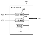
- each optical transceiver 110 includes at least an optical transmission unit 112, an optical reception unit 114, and a control unit 116.
- the optical transmitter 112 uses a variable frequency laser for DWDM / WDM communication, and outputs an optical signal of an arbitrary channel from channels standardized by ITU-T (International Telecommunication Union Telecommunication Standardization Sector).
- ITU-T International Telecommunication Union Telecommunication Standardization Sector
- description will be made on the assumption that the frequency tuning parameter described in Patent Document 2 (Japanese Patent No. 4596181) of the applicant of the present invention uses one frequency variable laser.
- This variable frequency laser uses liquid crystal and uses a filter capable of adjusting the transmission peak wavelength of the liquid crystal by an applied voltage.
- a frequency variable filter (not shown) is arranged as necessary before the optical receiving unit 114, and only the frequency of an arbitrary channel is selected and received.
- the frequency variable filter used in the frequency variable laser disclosed in Patent Document 2 is used as the frequency variable filter.
- the control unit 116 controls a tuning parameter related to the set frequency of the optical transmission unit 112 or the optical reception unit 114 in accordance with control from the optical transceiver control unit 150 described later.
- the control unit 116 follows the instruction from the optical transceiver control unit 150.
- the optical network 3 stands by in an off state so that the optical signal does not leak into the optical network 3.
- the control unit 116 sets an instructed channel (referred to as “standby channel”) according to an instruction from the optical transceiver control unit 150 (FIG. 1) while the optical transceiver 110 is on standby.
- the standby channel instructed to the standby optical transceiver 110 is assigned a different frequency among the plurality of optical transceivers 110 by the optical transceiver control unit 150.
- the difference in frequency between the setting channel and the standby channel can be reduced when setting the optical path when starting from the standby state. Since the smallest number of optical transceivers 110 can be selected, the time required to change the frequency setting from the standby channel to the setting channel can be shortened. This makes it possible to increase the speed of optical path setting.
- the set frequency can be used not only for setting the frequency variable laser of the optical transmitter 112 of the optical transceiver 110 but also for setting the frequency variable filter of the optical receiver 114 as required.
- transceiver aggregator 130 those similar to a frequency variable filter (not shown) are arranged, and when linked with the optical transceiver 110, the control unit 116 of each optical transceiver 110 and the optical transceiver 110 It is controlled similarly.
- tuning parameters for setting the frequency of each optical transceiver 110 are controlled by an instruction from the optical transceiver control unit 150.
- the operation of each component of the optical transceiver 110 according to the control is as follows. Since it is not related to the essence of the present invention, a detailed description is omitted.
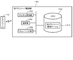
- FIG. 3 is a functional block diagram showing a configuration of the optical transceiver control unit 150 of the network device 100 according to the embodiment of the present invention.
- the optical transceiver control unit 150 grasps the connection state of the optical transceiver 110 to the network 3 (FIG. 1) and manages the usage state (used or unused) of the optical transceiver group 120 (FIG. 1). Furthermore, the optical transceiver control unit 150 controls a standby state of the standby optical transceiver (waiting when not in use, setting or stopping), and manages a channel setting for standby optical transceiver (standby channel setting). And a function of selecting which standby optical transceiver to use when setting a new path.
- the network device optical transceiver control unit 150 of the network device 100
- the network device has a variable frequency characteristic, and a plurality of transceivers (optical Transceiver 110), a channel assignment unit 154 that assigns different frequencies to the channels of the standby optical transceiver 110 that are not connected to the network 3 and set to the standby state among the plurality of optical transceivers 110, and the frequency of the assigned channel Tuning unit 158 that tunes standby optical transceiver 110 by changing parameters, and optical transceiver 110 that has a short channel setting time among standby optical transceivers 110 when a new path is set in network 3 Selection part 1 to use It includes a 6, a.
- the optical transceiver control unit 150 manages the channel allocation unit 154, the selection unit 156, the tuning unit 158, and the standby optical transceiver 110 (hereinafter referred to as “standby optical transceiver”).
- a memory 152 for storing the transceiver management table 160 is included.
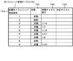
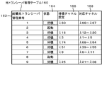
- an optical transceiver management table 160 for managing standby optical transceivers as shown in FIG. 4 is held.
- the optical transceiver control unit 150 manages the standby optical transceiver group 122 (FIG. 1) based on the table information of the optical transceiver management table 160.
- the channel allocation unit 154 allocates channels (frequencies) of the standby optical transceiver 110 that are not connected to the network 3 (FIG. 1) and set to the standby state among the plurality of transceivers 110 so as to be different from each other.
- the number N of the unconnected standby optical transceivers 110 is two or more, and the set frequencies of the N unconnected standby optical transceivers 110 are set at different frequencies.
- the channel assignment unit 154 records the assigned channel in the standby channel setting column 166 (FIG. 4) of the optical transceiver management table 160 stored in the memory 152.
- a plurality of standby optical transceiver channels are randomly allocated within the frequency range of the network device 100 using a random number function.
- the channel allocation unit 154 allocates the range of the corresponding channel based on the relationship between the frequency tuning parameter of the frequency variable laser of the optical transceiver 110, the frequency variable filter, and the allocated channel (frequency). Details of this allocation will be described later.
- the channel assignment unit 154 records the range of the corresponding channel allocated to each standby optical transceiver 110 in the corresponding channel column 168 of the optical transceiver management table 160 stored in the memory 152.
- the tuning unit 158 accesses the memory 152 and, based on the channel setting assigned by the channel assignment unit 154 recorded in the standby channel setting column 166 of the optical transceiver management table 160 of FIG. Tune by tuning and set the channel.
- the tuning parameter of the optical transceiver 110 is for setting the frequency (channel) of the frequency tunable laser or the frequency tunable filter.
- the refractive index, voltage or current of a medium such as a semiconductor, dielectric, or liquid crystal. Or including temperature.
- the tuning unit 158 controls these tuning parameters of each optical transceiver 110 in an analog manner.
- the frequency variable laser or the frequency variable filter used for the optical transceiver 110 is composed of only one type.
- the tuning unit 158 controls the output of the optical signal of the optical transceiver 110 to be off, and puts the optical transceiver 110 in a standby state. Further, when a new optical path is added, the tuning unit 158 tunes the optical transceiver 110 used for the new path to the channel of the new path, and then activates the optical signal output by turning it on.
- the selection unit 156 selects the optical transceiver 110 to be used when adding a new optical path.
- the selection unit 156 accesses the memory 152, refers to the optical transceiver management table 160, and selects the optical transceiver 110 in the channel range corresponding to the channel of the new optical path. In this manner, the selection unit 156 can preferentially select the unconnected standby optical transceiver 110 having a short frequency setting time when setting a new optical path.
- the switch 132 on the optical network 3 side is configured by a frequency selection switch or a splitter as described in Non-Patent Document 1.
- the transceiver aggregator 130 can use, for example, a configuration (wavelength path demultiplexing device) described in another invention (Japanese Patent Application No. 2010-213551) filed by the applicant of the present invention.
- the transceiver aggregator 130 includes a combination of AWGs (Arrayed Waveguide Gratings) and optical matrix switches equal to the number of ROADM (Reconfigurable Optical Add / Drop Multiplexer) Add or Drop paths, and the same number of transceivers as accommodated.
- An optical switch for switching the route is provided. Then, by connecting the optical matrix switch and the optical switch, a predetermined path and the transceiver can be connected.
- the transceiver aggregator 130 can share the optical transceiver 110 for a plurality of routes.
- a configuration other than this configuration is also possible.
- a configuration of a transceiver aggregator using a plurality of WSSs described in Non-Patent Document 1 is also possible.
- Each component of the network device 100 described above includes a CPU (Central Processing Unit), a memory, a program that realizes the components shown in the figure loaded in the memory, a storage unit such as a hard disk that stores the program, and a network connection. It is realized by an arbitrary combination of hardware and software of an arbitrary computer provided with an interface. It will be understood by those skilled in the art that there are various modifications to the implementation method and apparatus. Each figure described below shows functional unit blocks, not hardware unit configurations.
- the computer program of this embodiment is a standby optical transceiver that is not connected to the network 3 and is set in a standby state among a plurality of transceivers (optical transceiver 110) to a computer connected to the plurality of transceivers 110 having variable frequency characteristics.
- the computer program of this embodiment may be recorded on a computer-readable recording medium.
- the recording medium is not particularly limited, and various forms can be considered.
- the program may be loaded from a recording medium into a computer memory, or downloaded to a computer through a network and loaded into the memory.
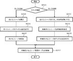
- FIG. 5 is a flowchart showing an example of the operation of the optical transceiver control unit 150 at the time of initial setting or change setting of the network device 100 of the present embodiment.
- an operation of the optical transceiver control unit 150 at the time of initial setting or change setting of the network device 100 of the present embodiment will be described with reference to FIGS. 1 to 8.
- FIGS. 6 to 8 and FIG. 4 are used for the state of the optical transceiver management table 160.
- the channel assignment unit 154 confirms the deployed optical transceiver group 120 and records the state of the optical transceiver 110 in the memory 152 (step S101).
- FIG. 6 shows an example of the optical transceiver management table 160 in the memory 152 of the optical transceiver control unit 150 at this time.
- the number of unused optical transceivers 110 can be detected by using the optical transceiver management table 160.
- the optical transceiver 110 is normally managed by network control with other nodes, and it is desirable that the management number of the optical transceiver 110 be shared with the management number for network control. Since the network control is not related to the essence of the present invention, a detailed description is omitted here.
- the channel allocation unit 154 of the optical transceiver control unit 150 selects the optical transceiver 110 that requires high-speed provisioning from the unused optical transceivers 110 and manages it as the standby optical transceiver group 122 (step S103).
- the channel allocation unit 154 of the optical transceiver control unit 150 accesses the memory 152 and changes the status column 164 of the optical transceiver management table 160 from “unused” to “standby” as shown in FIG. In this manner, the optical transceiver control unit 150 manages the state of the selected optical transceiver 110 and can check the number N of the waiting optical transceivers 110 by referring to the optical transceiver management table 160.
- all unused optical transceivers 110 are assumed to be standby optical transceivers 110.
- the control of the optical transceiver 110 on standby when the optical path is changed can be simplified, and the cost and power consumption of the system can be reduced.
- the unused optical transceiver 110 may be the standby optical transceiver 110. In this case, the control is complicated. However, the system described in another invention (Japanese Patent Application No. 2010-271150) filed by the present inventor can be adopted. In this method, only a part of unused optical transceivers 110 can be put into a standby state where high-speed activation can be performed, and the remaining unused optical transceivers 110 can be combined with a control in which the power is further reduced to a standby mode. is there. As a result, the power of the network device 100 can be suppressed. Further, by optimizing the number of optical transceivers waiting in a standby state in which high-speed activation is possible, it is possible to reduce effective power consumption in the entire optical network 3.
- the tuning unit 158 of the optical transceiver control unit 150 performs the initial setting to the standby state for the standby optical transceiver group 122 (step S105). At this time, the optical output of all the standby optical transceiver groups 122 is off.
- the channel assignment unit 154 of the optical transceiver control unit 150 assigns the frequency of the frequency variable laser or the frequency variable filter in the network device 100 (step S107).
- setting is performed by shifting so that the set frequencies of the optical transceivers 110 do not overlap.
- the channel allocation unit 154 allocates the frequency of the frequency variable filter and the frequency variable laser in each standby optical transceiver 110.
- the channel assignment unit 154 randomly assigns a plurality of channels of the waiting optical transceiver 110 within the frequency range of the network device 100.
- a random number function can be used. This random number function extracts a numerical value from an integer sequence corresponding to an ITU-T channel number corresponding to the optical transceiver control unit 150 by the network device 100 so as not to be randomly overlapped.
- the channel allocation unit 154 takes out random numbers corresponding to the number of standby optical transceivers in this random number function, and sets different frequencies for each standby optical transceiver based on the numerical values. Then, the channel assignment unit 154 accesses the memory 152 and records the set frequency in the standby channel setting column 166 of the optical transceiver management table 160 as shown in FIG.
- the set frequencies of the standby optical transceivers 110 are shifted so as not to overlap in order to increase the speed of setting the optical path, but random number control is complicated. However, the complexity of this control is not related to the optical path setting time. Therefore, it is also possible to simplify the control by allowing some overlap.
- the channel allocation unit 154 determines which standby optical transceiver to allocate to the channel at the time of setting a new path based on the relationship between the frequency tuning parameter of the frequency tunable laser and the frequency tunable filter and the channel (step S109). ). This allocation is performed so as to reduce the amount of tuning parameters when switching from each standby optical transceiver 110 to a channel for setting a new path. Details will be described later.
- the channels allocated in step S109 are recorded in the corresponding channel column 168 of the optical transceiver management table 160 as shown in FIG.
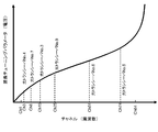
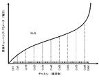
- FIG. 9 shows the relationship between the channel and the frequency tuning parameter (voltage) (shown as “wavelength tuning parameter” in FIG. 9) in the frequency variable filter or frequency variable laser used in this embodiment.
- the standby channel of each standby optical transceiver shown in the optical transceiver management table 160 of FIG. 8 is indicated by a broken line.
- the frequency tuning parameter value (voltage) of each channel is compared with the frequency tuning parameter value of the standby channel of each standby optical transceiver, and allocation is determined so as to minimize the parameter difference.
- the allocated channel range is recorded in the corresponding channel column 168 of the optical transceiver management table 160 as shown in FIG.
- the derivation is performed using the relationship between the tuning parameters of all frequency variable filters or frequency variable lasers and the selected frequency, but other methods may be used.
- the channel of the standby optical transceiver can be assigned based on the relationship between one frequency tuning parameter of the frequency tunable filter or frequency tunable laser and the channel.
- the allocation may be performed using the average characteristic.
- the relationship between the frequency tuning parameter and the selected frequency may be determined based on only the channel difference assuming that the relationship is linear approximation. Control is simplified by these methods, and control costs can be reduced.
- the frequency variable filters used in the respective optical transceivers 110 have the same configuration as in the present embodiment, it is not necessary to individually calculate tuning parameters, and control is simplified and speeded up. Control costs can be reduced. At least by unifying the frequency variable filters of the transmitter and the receiver of the optical transceiver 110, the control can be simplified, and the speed can be increased and the control cost can be reduced. In addition, when multiple different frequency variable filters are used and there is a difference in their operating speeds, control is simplified only by using a frequency variable filter with a slow operating speed, which speeds up control and reduces control costs. Is possible.
- FIG. 10 is a flowchart showing an operation at the time of setting an optical path of the optical transceiver control unit of the network device according to the embodiment of the present invention.
- 11 and 12 are diagrams illustrating an example of the optical transceiver management table after the optical path is set according to the embodiment of this invention.
- the channel assignment unit 154 of the optical transceiver control unit 150 checks a command related to the optical path setting from the network control unit (not shown) (step S201). If the command is to add an optical path, the process proceeds to step S203. If the command is to delete an optical path, the process proceeds to step S211.
- the network control unit remotely controls the plurality of network devices 100 on the optical network 3 to control communication. Since the control of the optical path setting from the network control unit is not related to the essence of the present invention, a detailed description thereof will be omitted.
- the selection unit 156 of the optical transceiver control unit 150 selects a standby optical transceiver that minimizes the amount of change in the tuning parameter.
- the selection is made based on the deployed optical transceiver management number column 162 of the optical transceiver management table 160 shown in FIG. For example, when setting a new path of the channel 40 ( ⁇ 40), the selection unit 156 accesses the memory 152, and the optical channel whose corresponding channel range 168 of the optical transceiver management table 160 includes ⁇ 40 is included. Transceiver No. 6 is selected. When setting a new path for the channel 10 ( ⁇ 10), the selection unit 156 selects the optical transceiver No. ⁇ 10 that includes ⁇ 10 in the corresponding channel range in the corresponding channel column 168 of the optical transceiver management table 160. 7 is selected.
- the tuning unit 158 of the optical transceiver control unit 150 tunes the standby optical transceiver 110 to the channel used in the new path and sets the channel (step S205). Then, the tuning unit 158 of the optical transceiver control unit 150 activates the standby optical transceiver (step S207). The optical signal output that was controlled to be off during standby is controlled to be on.
- FIG. 11 shows the update result of the optical transceiver management table 160 when the new path of the channel 40 is set.
- Optical transceiver No. used 6 is changed from “standby” to a use state (indicated as “activated” in the figure), and the optical transceiver No. 5 and optical transceiver no.
- Each of the nine corresponding channels is corrected, and the optical transceiver management table 160 is updated.
- This updating method is the same as the method described in step S109 in FIG.
- step S11 the tuning unit 158 of the optical transceiver control unit 150 turns off the optical output of the optical transceiver to be deleted and sets it to an unused state.
- the optical transceiver No. A case where 1 is stopped will be described.
- the tuning unit 158 of the optical transceiver control unit 150 sets the optical transceiver 110 that has been unused to a standby state as necessary.
- the tuning unit 158 of the optical transceiver control unit 150 sets the optical transceiver No. 1 is initially set as a standby state (step S213). This initial setting is the same as step S105 in FIG.
- the tuning unit 158 of the optical transceiver control unit 150 assigns a channel to the newly generated standby optical transceiver (step S215).
- the channel to be allocated is determined using the random number function described in step S107 in FIG.
- ⁇ 60 is assigned as shown in FIG.
- the tuning unit 158 records and updates the changed points in the above steps S211 to S215 in the optical transceiver management table 160 stored in the memory 152 (step S217).
- optical transceiver No. FIG. 12 shows the update result of the optical transceiver management table 160 when the optical path formed by 1 is deleted and the standby channel is assigned to ⁇ 60 in step S215.
- the optical transceiver No. 5 The corresponding channel of the optical transceiver that waits at the closest frequency on each of the long frequency side and the short frequency side with respect to one standby channel ⁇ 60 is also corrected.
- the corresponding channel of 5 is ⁇ 63 to ⁇ 84, but in FIG. 12, it can be seen that the channel is updated to ⁇ 68 to ⁇ 84.
- the corresponding frequency is determined by the method described in step S109 in FIG.
- the transceiver aggregator 130 and the switch 132 are also controlled, but are not described here because they are not related to the essence of the present invention.
- the time for setting a new optical path can be shortened.
- a standby optical transceiver when a standby optical transceiver is not prepared, a large delay occurs due to a delay in changing tuning parameters.
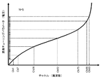
- the standby channel is fixed, and for example, it is fixed and arranged on channel 1 corresponding to the end of the frequency band used as the initial setting frequency. In this case, as shown in FIG. 13A, when the frequency is set at the end (channel 84) of another frequency band, the frequency change range is large, and it takes time to change the tuning parameter, resulting in a large delay. It was.
- the set frequencies of the standby optical transceiver group 122 are arranged in a frequency range corresponding to the network device 100. . Then, by selecting a standby optical transceiver that requires a small amount of change in the tuning parameter, the amount of change in the tuning parameter can be suppressed with a low probability, and the optical path setting time can be shortened.
- the optical transceiver No. 5 is selected and the frequency is set from the channel 74 to the channel 84, it can be seen that the change range of the frequency setting is significantly smaller than in the case of FIG.
- the method of controlling the network device 100 is such that the network device 100 that controls a plurality of transceivers (optical transceivers 110) having frequency variable characteristics is a network among the plurality of optical transceivers 110. 3 is not connected and is set to the standby state. A different frequency is assigned to the setting channel of the standby optical transceiver 110, the parameter is changed to the frequency of the assigned channel, and the standby optical transceiver 110 is tuned.
- the optical transceiver 110 having a short channel setting time is preferentially selected from the standby optical transceivers 110 when the path is set in the network.
- the frequency tuning parameter change for changing the frequency is changed. This makes it possible to reduce the amount, shorten the change time, and realize the network device 100 capable of setting an optical path at high speed.
- the optical network system of the present embodiment is different from the above-described embodiment in the frequency setting method of the frequency variable laser or frequency variable filter that is waiting in the network device 100.
- the network device 100 of the present embodiment is different from the above embodiment in that the standby optical transceiver channel is set so that the frequency interval is equal to the corresponding frequency band ⁇ f of the network device 100. Is different. This relates to the procedure of step S109 of FIG.
- the network device of the present embodiment has the same configuration as the network device 100 of the above-described embodiment described with reference to FIGS. 1 to 5 and FIG. This embodiment will also be described using the same configuration diagram.
- the channel allocation unit 154 when there are a plurality of standby optical transceivers among the plurality of optical transceivers 110, the channel allocation unit 154 includes N (N is an integer of 2 or more) standby optical transceivers. Are set to the settable frequencies closest to the center frequency of the frequency range ⁇ fi (i is an integer from 1 to N + 1) obtained by dividing the frequency range ⁇ f of the network device 100 by N.
- the channel assignment unit 154 assigns the standby optical transceiver channel to the corresponding frequency band ⁇ f of the network device 100 so that the frequency intervals are equal.
- Each channel of DWDM is standardized by ITU and has a constant frequency interval.
- This frequency setting method will be described when the number of standby optical transceivers is N.
- a frequency band covering channels 1 to 90 is considered as the frequency band ⁇ f.
- this frequency band ⁇ f is divided by N.
- a channel near the center frequency of the divided frequency band ⁇ fi (i is an integer from 1 to N) is set as a setting channel of each standby optical transceiver, and the channel allocation unit 154 stores the optical transceiver management table 160 stored in the memory 152. Record in the standby channel setting field 166. Further, the channel allocation unit 154 records the channel range within the frequency band ⁇ fi in the corresponding channel column 168 of the optical transceiver management table 160 stored in the memory 152 as a corresponding channel.
- the same effect as that of the above embodiment can be obtained, and furthermore, the set frequencies of the standby optical transceiver groups are evenly arranged, so in the case of FIG. In comparison, the amount of tuning parameters for setting the frequency is suppressed to about 1 / N. Thereby, the time for setting a new optical path can be shortened. Furthermore, the present embodiment is a simple control equivalent to the above-described embodiment, and the control time and cost can be reduced.
- the optical network system of the present embodiment is different from the above-described embodiment in the frequency setting method of the frequency variable laser or frequency variable filter that is waiting in the network device 100.
- the network device 100 of the present embodiment is different from the above-described embodiment in that the frequency tuning parameter values of the standby optical transceiver are set at equal intervals with respect to the frequency tuning parameter setting range. .
- This relates to the procedure of step S109 of FIG.
- the network device of the present embodiment has the same configuration as the network device 100 of the above-described embodiment described with reference to FIGS. 1 to 5 and FIG. This embodiment will also be described using the same configuration diagram.
- the channel allocating unit 154 divides the frequency tuning parameter range of parameters necessary for tuning the frequency range ⁇ f of the network device 100 into N, and divides the frequency of the N standby optical transceiver channels. Set at the center value of the N frequency tuning parameter ranges.
- the channel allocation unit 154 makes the frequency tuning parameter value of the standby optical transceiver equal to the tuning parameter setting range.
- This frequency channel setting method will be described when the number of standby optical transceivers is N.
- the tuning parameter range is divided by N.
- the standby optical transceiver is set to the corresponding closest channel near the center value of each divided tuning parameter band.
- the corresponding channel allocation range recorded in the corresponding channel column 168 of the optical transceiver management table 160 is the same as that in the above embodiment.
- the network device since the setting channels of the standby optical transceiver group are evenly arranged with respect to the tuning parameter, the amount of tuning parameter for frequency setting can be suppressed to 1 / N or less. As a result, the time for setting a new optical path can be shortened. Furthermore, the network device according to the present embodiment has simple control equivalent to that of the above-described embodiment described with reference to FIG. 14, and can shorten control time and cost.
- a single tuning parameter has been described.
- a frequency tunable laser or a frequency tunable filter having two or more tuning parameters can be handled with the same idea.
- evenly dividing all the tuning parameters is complicated in terms of control.
- it is possible to achieve both simplification of control and shortening of the tuning time by preferentially dividing a parameter having a large tuning parameter delay.
- the optical network system 200 according to the present embodiment is different from the above-described embodiment in that it further includes a network management control unit 210 that manages communication between nodes. Note that the optical network system 200 of the present embodiment can be employed in any configuration of the above-described embodiments.
- FIG. 16 shows a basic configuration of an optical network system 200 according to the embodiment of the present invention.
- an acquisition unit network management control unit 210) that acquires empty channel information that can be newly set in the network 3 in the network device 100, and the acquired empty channel information
- a determination unit (not shown, which can be included in the channel allocation unit 154) that sets the frequency range ⁇ fa that can be set to N and determines the channels of the N standby optical transceivers 110 based on ⁇ fa instead of ⁇ f.
- the channel assignment unit 154 sets the determined N standby optical transceiver 110 channels.
- the optical network system 200 of the present embodiment includes a transceiver aggregator 130, a switch 132, a plurality of optical transceivers 110, and an optical transceiver control unit 150 similar to those of the network device 100 of the above embodiment. And a network management control unit 210 that manages communication between the nodes.
- the network management control unit 210 obtains free channel information regarding each route from the control plane 202 that controls between adjacent nodes and the entire network.
- the free channel information is provided to the optical transceiver control unit 150.
- the channel assignment unit 154 of the optical transceiver control unit 150 grasps a channel that may be newly set based on the empty channel information.
- the channel allocation unit 154 extracts a channel range that can be taken from the empty channel information, and sets the frequency of the standby optical transceiver based on the channel range. Note that the operation procedure of this embodiment can use the same procedure as that of the above-described embodiment except for the setting of the frequency range.
- the setting channel of the standby optical transceiver can be set to an empty channel. This eliminates the need for tuning time and makes it possible to speed up the optical path setting.
- the same effect as that of the above embodiment can be obtained, and the frequency setting range can be suppressed to be small according to the use state of the network.
- the tuning time can be further increased.
- the optical network system using the wavelength multiplexing technique has been described, but the present invention is not limited to this.
- the present invention can be applied to a system using a multiplexing technique and all systems that perform the multiplexing by tuning using an analog technique. Considering application to wavelength multiplexing technology, it can be applied to optical communication systems and wireless communication systems in general.
- the selection unit 156 can preferentially select the optical transceiver closest to the channel frequency of the newly set path from the channel frequency of the standby optical transceiver to which the channel allocation unit 154 has allocated the channel. According to this configuration, it is not necessary to consider the tuning parameter in the channel assignment update process of the optical transceiver management table 160 after selection, and the process can be simplified.
- the present invention can also include the following aspects.
- Appendix 1 A plurality of transceivers having variable frequency characteristics, each communicating on an assigned channel; Channel allocating means for allocating different frequencies to the channels of the standby transceiver that is not connected to the network among the plurality of transceivers and is set in a standby state; Tuning means for changing the parameter to the frequency of the assigned channel to tune the standby transceiver; Selection means for preferentially selecting and using a transceiver having a short channel setting time from among the standby transceivers when setting a new path in the network;
- a network device comprising: (Appendix 2) In the network device according to attachment 1, When there are a plurality of the standby transceivers among the plurality of the transceivers,
- the channel allocation means is a network device that randomly allocates the channels of a plurality of standby transceivers within a frequency range of the network device.
- the channel allocating unit is a network device that allocates the channels of the plurality of standby transceivers at random within a frequency range of the network device so as not to overlap.
- the channel allocating means has a frequency range ⁇ fi (i is an integer from 1 to N + 1) obtained by dividing the channel range of the standby transceiver by N (N is an integer of 2 or more) by dividing the frequency range ⁇ f of the network device by N.
- a network device that sets each of the settable frequencies closest to the center frequency. (Appendix 5) In the network device according to attachment 1, When there are a plurality of standby transceivers among a plurality of the transceivers, the number of the plurality of standby transceivers is N (N is an integer of 2 or more),
- the channel allocating unit divides the frequency tuning parameter range of the parameter necessary for tuning the frequency range ⁇ f of the network device into N, and divides the frequency of the channel of the N standby transceivers.
- a network device configured to set the center value of the N frequency tuning parameter ranges.
- (Appendix 6) In the network device according to any one of supplementary notes 2 to 5, Acquisition means for acquiring free channel information that can be newly set in the network in the network device; Determining means for setting a frequency range ⁇ fa that can be obtained based on the acquired empty channel information, and determining the channels of the N standby transceivers based on the ⁇ fa instead of the ⁇ f;
- the channel allocating unit is a network device that sets the channels of the N number of standby transceivers determined by the determining unit.
- the selection unit is a network device that preferentially selects a transceiver closest to the frequency of the channel of the path to be newly set from the frequency of the channel of the standby transceiver to which the channel allocation unit has allocated the channel.
- the transceiver is an optical transceiver; An optical transceiver aggregator having a matrix switch, which can connect any optical transceiver to any optical fiber at any optical frequency with respect to an optical fiber group composed of a plurality of optical fibers connected to a plurality of different network devices.
- the transceiver is a network device including only one type of frequency variable laser.
- the transceiver is a network device including only one type of variable frequency filter.
- the transceiver includes a variable frequency selection device that selects one frequency from a plurality of frequencies, The frequency variable selection device is a network device having one frequency tuning parameter.
- the channel allocation unit is a network device that allocates a channel of the standby transceiver based on a relationship between a frequency tuning parameter of the frequency variable selection device to be used and a channel.
- the channel allocation means allocates the channel of the standby transceiver based on the relationship between one frequency tuning parameter of the frequency variable selection device to be used and the channel. .
- the channel of N standby transceivers (N is an integer of 2 or more) is set closest to the center frequency of a frequency range ⁇ fi (i is an integer from 1 to N + 1) obtained by dividing the frequency range ⁇ f of the network device by N.
- Network control method to set each possible frequency.
- Appendix 22 A computer connected to a plurality of transceivers having variable frequency characteristics to realize a network device, A step of assigning different frequencies to the setting channel of the standby transceiver that is not connected to the network among the plurality of the transceivers and sets to the standby state; Tune the standby transceiver by changing parameters to the frequency of the assigned channel; A program for executing a procedure for preferentially selecting and using a transceiver having a short channel setting time from among the standby transceivers when setting a new path in the network.
- Appendix 23 In the program described in Appendix 22, When there are a plurality of the standby transceivers among the plurality of the transceivers, A program for causing a computer to further execute a procedure for randomly allocating the channels of a plurality of standby transceivers within a frequency range of the network device.
- Appendix 24 In the program described in Appendix 22, When there are a plurality of the standby transceivers among the plurality of the transceivers, A program for causing a computer to further execute a procedure for allocating the channels of a plurality of standby transceivers randomly and without overlapping within a frequency range of the network device.
- Appendix 26 In the program described in Appendix 22, When there are a plurality of standby transceivers among a plurality of the transceivers, the number of the plurality of standby transceivers is N (N is an integer of 2 or more), The frequency tuning parameter range of the parameters required to tune the frequency range ⁇ f of the network device is divided into N, and the frequency of the channel of the N standby transceivers is divided into the N pieces of the divided A program that causes the computer to further execute the procedure for setting the center value of the frequency tuning parameter range.
Landscapes
- Engineering & Computer Science (AREA)
- Computer Networks & Wireless Communication (AREA)
- Signal Processing (AREA)
- Physics & Mathematics (AREA)
- Electromagnetism (AREA)
- Optical Communication System (AREA)
- Data Exchanges In Wide-Area Networks (AREA)
Abstract
Priority Applications (2)
| Application Number | Priority Date | Filing Date | Title |
|---|---|---|---|
| JP2013526748A JP5983609B2 (ja) | 2011-07-29 | 2012-07-27 | ネットワークシステム、ネットワーク装置、およびネットワーク制御方法 |
| US14/235,305 US9240856B2 (en) | 2011-07-29 | 2012-07-27 | Network system, network apparatus, and method of controlling network |
Applications Claiming Priority (2)
| Application Number | Priority Date | Filing Date | Title |
|---|---|---|---|
| JP2011-166222 | 2011-07-29 | ||
| JP2011166222 | 2011-07-29 |
Publications (1)
| Publication Number | Publication Date |
|---|---|
| WO2013018337A1 true WO2013018337A1 (fr) | 2013-02-07 |
Family
ID=47628888
Family Applications (1)
| Application Number | Title | Priority Date | Filing Date |
|---|---|---|---|
| PCT/JP2012/004797 Ceased WO2013018337A1 (fr) | 2011-07-29 | 2012-07-27 | Système de réseau, dispositif de réseau et procédé de contrôle de réseau |
Country Status (3)
| Country | Link |
|---|---|
| US (1) | US9240856B2 (fr) |
| JP (1) | JP5983609B2 (fr) |
| WO (1) | WO2013018337A1 (fr) |
Families Citing this family (10)
| Publication number | Priority date | Publication date | Assignee | Title |
|---|---|---|---|---|
| JP5904320B2 (ja) * | 2011-09-22 | 2016-04-13 | 日本電気株式会社 | 光通信装置、光通信システム、および経路制御方法 |
| US8965198B2 (en) * | 2012-04-13 | 2015-02-24 | Fujitsu Limited | System and method for shared mesh restoration in optical networks |
| US9413488B2 (en) * | 2013-09-21 | 2016-08-09 | Mark E. Boduch | Method and apparatus for optical transmitter and receiver redundancy within a directionless optical node |
| US9699074B2 (en) * | 2014-04-10 | 2017-07-04 | Fujitsu Limited | Efficient utilization of transceivers for shared restoration in flexible grid optical networks |
| WO2015162875A1 (fr) * | 2014-04-24 | 2015-10-29 | 日本電気株式会社 | Dispositif de nœud optique, dispositif de commande de réseau optique, et procédé de commande de réseau optique |
| ES2678947T3 (es) * | 2014-07-15 | 2018-08-21 | Huawei Technologies Co. Ltd. | Método, aparato y sistema de comunicación para red óptica pasiva |
| CN106537852B (zh) * | 2014-07-24 | 2019-10-01 | 日本电信电话株式会社 | 光通信系统、站侧装置、用户装置以及光通信方法 |
| WO2016023180A1 (fr) | 2014-08-13 | 2016-02-18 | 华为技术有限公司 | Procédé, dispositif et système de communication pour un réseau optique passif |
| JP2017163358A (ja) * | 2016-03-09 | 2017-09-14 | 富士通株式会社 | ネットワーク管理装置、ネットワークシステム、ネットワーク管理方法、及びネットワーク管理プログラム |
| US10411806B2 (en) * | 2016-06-29 | 2019-09-10 | Ciena Corporation | Gridless optical routing and spectrum assignment |
Citations (2)
| Publication number | Priority date | Publication date | Assignee | Title |
|---|---|---|---|---|
| JPH03214831A (ja) * | 1990-01-19 | 1991-09-20 | Canon Inc | 光通信機器 |
| JP2011101216A (ja) * | 2009-11-06 | 2011-05-19 | Fujitsu Ltd | 光伝送装置及び波長可変光出力ユニットの制御方法 |
Family Cites Families (17)
| Publication number | Priority date | Publication date | Assignee | Title |
|---|---|---|---|---|
| US5212577A (en) | 1990-01-19 | 1993-05-18 | Canon Kabushiki Kaisha | Optical communication equipment and optical communication method |
| US5949562A (en) * | 1994-11-30 | 1999-09-07 | Canon Kabushiki Kaisha | Transmission wavelength control method permitting efficient wavelength multiplexing, optical communication method, optical transmitter, optical transmitter-receiver apparatus, and optical communication system |
| JP3566496B2 (ja) * | 1996-05-27 | 2004-09-15 | キヤノン株式会社 | 波長制御方法及びそれを用いるネットワークシステム |
| JPH10209964A (ja) * | 1997-01-28 | 1998-08-07 | Fujitsu Ltd | 波長多重送受信装置、光伝送システム及びその冗長系切替え方法 |
| JP3060994B2 (ja) * | 1997-05-15 | 2000-07-10 | 日本電気株式会社 | N−wdmシステムにおける出力ポート切替装置 |
| US7099578B1 (en) * | 1999-12-16 | 2006-08-29 | Tellabs Operations Inc. | 1:N protection in an optical terminal |
| US6970250B1 (en) | 2000-01-20 | 2005-11-29 | Agilent Technologies, Inc. | Method and system for optical heterodyne detection of an optical signal that utilizes optical attenuation |
| JP2003087194A (ja) * | 2001-09-10 | 2003-03-20 | Photonixnet Corp | 光送受信機及び通信伝送媒体変換器 |
| JP2004361818A (ja) * | 2003-06-06 | 2004-12-24 | Fujitsu Ltd | 信号光送出部 |
| JP2006042155A (ja) * | 2004-07-29 | 2006-02-09 | Fujitsu Ltd | 冗長構成された光波長分割多重伝送装置及び、予備系光出力の波長制御方法 |
| CN101212254A (zh) * | 2006-12-27 | 2008-07-02 | 华为技术有限公司 | 一种光源链路传输装置和方法 |
| JP4596181B2 (ja) | 2007-03-28 | 2010-12-08 | 日本電気株式会社 | 外部共振器型波長可変半導体レーザ |
| EP2043308B1 (fr) * | 2007-09-27 | 2012-01-25 | Hitachi, Ltd. | GMPLS dans les réseaux optiques |
| JP5545212B2 (ja) * | 2008-05-26 | 2014-07-09 | 日本電気株式会社 | 波長パス通信ノード装置、波長パス通信制御方法、プログラム、および記録媒体 |
| JP5221678B2 (ja) * | 2008-12-18 | 2013-06-26 | 富士通テレコムネットワークス株式会社 | Fbtl光モジュールの波長制御をする波長分割多重伝送装置とfbtl光モジュールを備える波長分割多重伝送装置の波長制御方法 |
| JP5113093B2 (ja) | 2009-01-06 | 2013-01-09 | Kddi株式会社 | ネットワークの管理システム及び管理方法 |
| US20110286746A1 (en) * | 2009-10-09 | 2011-11-24 | Nec Laboratories America, Inc. | Transponder Aggregator Without Wavelength Selector for Colorless and Directionless Multi-Degree ROADM Node |
-
2012
- 2012-07-27 WO PCT/JP2012/004797 patent/WO2013018337A1/fr not_active Ceased
- 2012-07-27 JP JP2013526748A patent/JP5983609B2/ja active Active
- 2012-07-27 US US14/235,305 patent/US9240856B2/en active Active
Patent Citations (2)
| Publication number | Priority date | Publication date | Assignee | Title |
|---|---|---|---|---|
| JPH03214831A (ja) * | 1990-01-19 | 1991-09-20 | Canon Inc | 光通信機器 |
| JP2011101216A (ja) * | 2009-11-06 | 2011-05-19 | Fujitsu Ltd | 光伝送装置及び波長可変光出力ユニットの制御方法 |
Also Published As
| Publication number | Publication date |
|---|---|
| JPWO2013018337A1 (ja) | 2015-03-05 |
| US20140133863A1 (en) | 2014-05-15 |
| JP5983609B2 (ja) | 2016-09-06 |
| US9240856B2 (en) | 2016-01-19 |
Similar Documents
| Publication | Publication Date | Title |
|---|---|---|
| JP5983609B2 (ja) | ネットワークシステム、ネットワーク装置、およびネットワーク制御方法 | |
| US10887041B2 (en) | Flexible grid optical spectrum transmitter, receiver, and transceiver | |
| US10670811B2 (en) | Microring resonator control method and apparatus | |
| US9577410B2 (en) | Optical functional integrated unit and method for manufacturing thereof | |
| US10448128B2 (en) | Optical switch device | |
| JP6115364B2 (ja) | 光伝送装置、光伝送システム、及び光伝送方法 | |
| EP3491754B1 (fr) | Procédé et système pour commander un dispositif à occupation spectrale | |
| JP5093089B2 (ja) | ネットワーク設計装置およびネットワーク設計方法 | |
| JP6260689B2 (ja) | 光通信装置、光通信システム及び光送信方法 | |
| US9831978B1 (en) | Method and system for controlling spectral occupancy | |
| Masood et al. | Networking assessment of ROADM architecture based on a photonics integrated WSS for 800G multi-band optical transport | |
| Mutafungwa | An improved wavelength-selective all-fiber cross-connect node | |
| WO2020194859A1 (fr) | Système de communication optique, émetteur-récepteur optique, procédé de communication optique et support non transitoire lisible par ordinateur | |
| US6701031B2 (en) | Acousto-optical tunable filter, method of driving the same, and optical add/drop multiplexer | |
| KR100585318B1 (ko) | 파장 분할 다중화 그물망 구조에서의 동적 파장 경로 제어방법 | |
| US7349632B2 (en) | Method of wavelength selection control and wavelength variable filter device | |
| US20040136717A1 (en) | Non-blocking tunable filter with flexible bandwidth for reconfigurable optical networks | |
| JP2006330515A (ja) | 音響光学型チューナブルフィルタ制御装置、および波長選択方法 | |
| Masood et al. | Network Traffic Analysis of Modular Multiband Integrated WSS based ROADMs | |
| Porzi et al. | Silicon photonics comb demultiplexer for elastic optical networks | |
| Turkcu et al. | Blocking and waveband assignment in WDM networks with limited reconfigurability | |
| Anderson Bravalheri et al. | Experimental Validation of Time-Synchronized Operations for Software-defined Elastic Optical Networks | |
| CN121727679A (zh) | 光信号传输方法、光节点、介质及产品 | |
| WO2025253538A1 (fr) | Dispositif de traitement d'informations, procédé de traitement d'informations et programme | |
| JPH10262031A (ja) | 光通信システム |
Legal Events
| Date | Code | Title | Description |
|---|---|---|---|
| 121 | Ep: the epo has been informed by wipo that ep was designated in this application |
Ref document number: 12819828 Country of ref document: EP Kind code of ref document: A1 |
|
| ENP | Entry into the national phase |
Ref document number: 2013526748 Country of ref document: JP Kind code of ref document: A |
|
| WWE | Wipo information: entry into national phase |
Ref document number: 14235305 Country of ref document: US |
|
| NENP | Non-entry into the national phase |
Ref country code: DE |
|
| 122 | Ep: pct application non-entry in european phase |
Ref document number: 12819828 Country of ref document: EP Kind code of ref document: A1 |