WO2013018566A1 - Dispositif de fabrication d'une grille déployée - Google Patents
Dispositif de fabrication d'une grille déployée Download PDFInfo
- Publication number
- WO2013018566A1 WO2013018566A1 PCT/JP2012/068560 JP2012068560W WO2013018566A1 WO 2013018566 A1 WO2013018566 A1 WO 2013018566A1 JP 2012068560 W JP2012068560 W JP 2012068560W WO 2013018566 A1 WO2013018566 A1 WO 2013018566A1
- Authority
- WO
- WIPO (PCT)
- Prior art keywords
- roll
- expanded
- ear
- direction changing
- expanded lattice
- Prior art date
- Legal status (The legal status is an assumption and is not a legal conclusion. Google has not performed a legal analysis and makes no representation as to the accuracy of the status listed.)
- Ceased
Links
Images


Classifications
-
- H—ELECTRICITY
- H01—ELECTRIC ELEMENTS
- H01M—PROCESSES OR MEANS, e.g. BATTERIES, FOR THE DIRECT CONVERSION OF CHEMICAL ENERGY INTO ELECTRICAL ENERGY
- H01M4/00—Electrodes
- H01M4/02—Electrodes composed of, or comprising, active material
- H01M4/64—Carriers or collectors
- H01M4/70—Carriers or collectors characterised by shape or form
- H01M4/72—Grids
- H01M4/74—Meshes or woven material; Expanded metal
- H01M4/745—Expanded metal
-
- H—ELECTRICITY
- H01—ELECTRIC ELEMENTS
- H01M—PROCESSES OR MEANS, e.g. BATTERIES, FOR THE DIRECT CONVERSION OF CHEMICAL ENERGY INTO ELECTRICAL ENERGY
- H01M4/00—Electrodes
- H01M4/02—Electrodes composed of, or comprising, active material
- H01M4/64—Carriers or collectors
- H01M4/70—Carriers or collectors characterised by shape or form
- H01M4/72—Grids
- H01M4/73—Grids for lead-acid accumulators, e.g. frame plates
-
- Y—GENERAL TAGGING OF NEW TECHNOLOGICAL DEVELOPMENTS; GENERAL TAGGING OF CROSS-SECTIONAL TECHNOLOGIES SPANNING OVER SEVERAL SECTIONS OF THE IPC; TECHNICAL SUBJECTS COVERED BY FORMER USPC CROSS-REFERENCE ART COLLECTIONS [XRACs] AND DIGESTS
- Y02—TECHNOLOGIES OR APPLICATIONS FOR MITIGATION OR ADAPTATION AGAINST CLIMATE CHANGE
- Y02E—REDUCTION OF GREENHOUSE GAS [GHG] EMISSIONS, RELATED TO ENERGY GENERATION, TRANSMISSION OR DISTRIBUTION
- Y02E60/00—Enabling technologies; Technologies with a potential or indirect contribution to GHG emissions mitigation
- Y02E60/10—Energy storage using batteries
Definitions
- the present invention relates to an apparatus for manufacturing an expanded lattice.
- Expanded grids are mainly used for lead-acid batteries for automobiles, and are widely used because they are easy to manufacture.
- an electrolytic solution and positive and negative electrodes immersed in the electrolytic solution are arranged in a battery case, and an expanded lattice is used as a substrate for the electrode.
- the expanded lattice is manufactured mainly from a sheet-like material containing lead as a main material. After the incision is made with a cutter, the expanded method is used to expand the incised portion, and the cutter. At the same time as making the incision, it is divided into a simultaneous expansion method in which the cut portion is expanded, and the simultaneous expansion method is further divided into a parallel cutter method and a right angle cutter method depending on the direction of the blade of the cutter. The sheet-like material after the expansion is punched to form an ear portion that becomes a current collecting portion. After punching, the expanded lattice is filled with a paste-like active material, divided into individual expanded lattices, and after drying and aging, becomes an electrode plate.
- the apparatus for producing an expanded lattice has an expanding processing means 3 for producing an expanded portion and an ear punching means 6 for forming a portion sandwiched between the expanded lattices at the ear portion.
- the expanding lattice is conveyed using the feeding means 4 composed of rollers.
- the expanding lattice manufacturing apparatus shown in Patent Document 1 expands the strip 2 (sheet-like material) by the expanding processing means 3, it expands sequentially from the outside of the sheet, but the central portion is unprocessed. In order to leave a part, distortion remains from the difference in the amount of extension, and a deflection and a wave
- the present invention removes the undulation and deflection from the expanding processing means of the sheet material containing lead as a main raw material until reaching the ear punching means, and the ear punching means in a flat state.
- An object of the present invention is to provide an expanding lattice manufacturing apparatus that can be transported to the outside.
- the expanded lattice manufacturing apparatus according to the present invention is as follows.
- Expanding means for sheet material containing lead as a main material, ear punching means for forming an ear of an expanded lattice processed by the expanding means by punching, and ear punching from the expanding means A conveying direction changing roll provided in the middle of conveying the expanded lattice to the means, and a pair of upper and lower flattening rolls provided downstream of the conveying direction changing roll and passing the expanded lattice, the conveying direction changing roll
- it has the maximum diameter in the axial center part of the roll.
- it has the maximum in the same dimensional position from a center part in the intermediate position which goes to an axial direction center part and both ends.
- the flattening roll is characterized in that either one of the upper and lower roll surfaces is made of resin, and the other roll surface is made of metal.
- a roll whose surface is made of metal is a drive roll, and a roll whose surface is made of resin is a driven roll.
- the transport direction changing roll has a maximum diameter in the central portion in the axial direction of the roll. Or, it is assumed that it has the maximum at the same dimensional position from the central part at the intermediate position from the central part in the axial direction to remove the waviness with the subsequent flattening roll.
- the expanded lattice can be conveyed to the ear punching means while maintaining the planar shape. Therefore, the subsequent paste-like active material filling can be reliably performed without causing defects.
- the flattening roll is made of one of the upper and lower surfaces made of resin and the other surface is made of metal, than when the upper and lower roll surfaces are made of resin, Since the crushing effect is enhanced, even if the sheet is an expanded lattice having a thick and high rigidity, the swell can be removed and flattened. And since one surface is made from resin, there is no slip of an expanded lattice in the case of conveyance.
- the feed roll 3 is sandwiched between the expanding processing means 1 and the ear punching means 2.
- the feed roll 3 includes a transport direction changing roll 5, a tension roll 6, and a flattening roll 7.
- the expand processing means 1 described in the present invention is not particularly limited as long as a sheet-like material containing lead as a main material is expanded, and any of the post-expansion method or the simultaneous expansion method described above. Any of the parallel cutter method and the right angle cutter method can be used as long as it is a simultaneous expansion method.
- the expanding means 1 is preferably performed by the simultaneous expansion method, and the expanding means 1 of the simultaneous expansion method is left on both sides of the sheet-like material (for example, lead alloy strip) in the width direction.
- the process is expanded to form a continuous expanded lattice.
- there is also a rear expansion method but if you want to easily obtain high accuracy after changing the parts of the processing machine when changing the expanded deployment shape, Rather than performing fine adjustment of the spreading blade, a simultaneous spreading method in which the unitized simultaneous spreading portions are completely replaced is preferable.
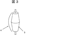
- the transport direction changing roll 5 described in the present invention changes the transport direction of the expanded lattice 4 discharged from the expanding processing means 1, and has a maximum diameter in the central portion in the axial direction of the roll. Or it is not restrict
- FIG. 2 shows a side view of the transport direction changing roll 5.
- a roller having a maximum diameter at the central portion in the axial direction of the roll can be used that inclines along a gentle curve from the central portion in the roll axial direction toward both ends of the roll.
- a gentle curve is convex upward, but it can also be a downward convex curve. It may be a straight line instead of a curve.
- the maximum diameter at the central portion in the axial direction is the maximum diameter with an equal dimension width from the central portion in the axial direction toward both ends, and from the edge on the maximum diameter side to the end portion. It is possible to use one that is connected by a curved line with a convex upward.
- the expanded lattice 4 is bent at the portion in contact with the transport direction changing roll 5 by pushing up the central portion in the width direction of the expanded lattice 4 or in the vicinity of the center. It transforms into a uniform barrel shape as a whole. And this barrel type
- the diameter of the transport direction changing roll 5 is appropriately set. Specifically, the maximum diameter can be set to 100 to 500 mm, and the minimum diameter can be set to 10 to 100 mm.
- the material of the transport direction change roll 5 is not particularly limited as long as it has a higher altitude than the expanded lattice 4. Specifically, iron, stainless steel or the like can be used, and stainless steel is used among them. It is preferable because of excellent strength and corrosion resistance.
- the tension roll 6 described in the present invention is provided in the middle of feeding the sheet-like workpiece 4 sent from the transport direction changing roll 5 to the next flattening roll 7. Since the expanding processing means 1 has a high processing speed, the expanded lattice 4 is sent in a state of being slack to some extent in order to be connected to the next step. The tension roll 6 moves up and down, and sends the sheet-like material 4 to the flattening roll 7 with a certain tension applied.
- the flattening roll 7 described in the present invention is provided on the downstream side of the transport direction changing roll 5 and is a pair of upper and lower rolls through which the expanded lattice 4 passes.
- the flattening roll 7 flattens the barrel-shaped expanded lattice material 4 by passing and sandwiching the expanded lattice 4 between the upper roll and the lower roll, and one roll surface is made of resin.
- the other roll surface is preferably made of metal.
- the resin constituting the surface of the one roll is not particularly limited, but polypropylene, vinyl chloride resin, polyethylene terephthalate, and the like can be used. In particular, it is preferable in terms of cost to use polypropylene.
- the resin roll surface is preferably formed by coating a metal roll with a resin layer having a thickness of 3 to 30 mm. If it is less than 3 mm, the expanded lattice is crushed too much because the elasticity of the resin is small. On the contrary, when the thickness exceeds 30 mm, there is no difference in effect, and only the cost increases.
- the material when the surface of the flattening roll is made of metal may be the same as or different from the material of the transfer direction changing roll, but it is desirable that the thermal expansion coefficient is the same, so the same material should be used. preferable.
- the metal is not particularly limited, but iron, stainless steel, and the like can be used. In particular, it is preferable to use a material obtained by subjecting iron to plating.
- the surface of the flattening roll made of resin and the one made of metal may be either the upper roll or the lower roll, but the roll whose surface is made of metal is the driving roll, and the roll made of resin is the driven roll It is preferable that This is because resin rolls need to be replaced due to wear more frequently than metal rolls, so it is easier to replace them with a driven roll that can complete the replacement work in a shorter time. is there.
- the ear punching means 2 described in the present invention forms the ears of the expanded lattice by press working using a mold. Moreover, it can also carry out with the rotary-type cutting machine which gave the processing tooth for punching to the surface of the roll.
- Example 1 As a basic design, the expand manufacturing apparatus shown in FIG. 1 is used. At this time, the conveyance direction changing roll 5 having the shape shown in FIG. This is an axial length: 400 mm, a maximum diameter in the axial center: 160 mm, and a minimum diameter at both axial ends: 100 mm. And the thing which connected the axial direction center and the axial direction both ends linearly was used. As the flattening roll 7, a driving roll whose surface was made of metal and a driven roll whose surface was made of metal were used.
- Example 2 a driving roll whose surface was made of metal and a driven roll whose surface was made of resin (resin: polypropylene, resin layer thickness: 20 mm) were used as the flattening roll 7.
- the driven roll is made of metal having an axial length of 400 mm and a roll diameter of 100 mm, and has a configuration in which a central portion in the axial direction is coated with the resin layer at 30 mm.
- Example 3 a driving roll whose surface was made of metal and a driven roll whose surface was made of resin (resin: polypropylene, resin layer thickness: 20 mm) were used as the flattening roll 7.
- the driven roll is made of metal having an axial length of 400 mm and a roll diameter of 100 mm, and has a configuration in which the central portion in the axial direction is coated with the resin layer at 100 mm.
- Example 4 a driving roll whose surface was made of metal and a driven roll whose surface was made of resin (resin: polypropylene, resin layer thickness: 20 mm) were used as the flattening roll 7.
- the driven roller is made of metal having an axial length of 400 mm and a roll diameter of 100 mm, and is configured to be covered with the resin layer over the entire axial length.
- Example 1 In Comparative Example 1, waviness and deflection occur frequently in the expanded lattice, the process is frequently stopped, and there are many dimensional anomalies. In contrast, in Examples 1 to 4 of the present invention, they were improved. In particular, in Example 4, the entire surface of the flattening roll was covered with a resin, so that an expanded lattice without dimensional abnormality could be stably manufactured.
- Examples 1 to 4 described above relate to the shape of FIG. 2 (a), but similar effects were also obtained with the shapes of FIGS. 2 (b) and 2 (c).
Landscapes
- Chemical & Material Sciences (AREA)
- Chemical Kinetics & Catalysis (AREA)
- Electrochemistry (AREA)
- General Chemical & Material Sciences (AREA)
- Cell Electrode Carriers And Collectors (AREA)
Abstract
La présente invention concerne un dispositif de fabrication d'une grille déployée qui supprime l'ondulation et la courbure d'une grille déployée jusqu'à ce que la grille atteigne un moyen de perforation d'ouïes à partir d'un moyen de déploiement, qui déploie un matériau en feuille principalement composé de plomb, dans le but de permettre que la grille soit transportée à plat vers le moyen de perforation d'ouïes. Le dispositif de fabrication de grille déployée comporte : un moyen de déploiement pour le déploiement d'une feuille en plomb ou en alliage de plomb ; un moyen de perforation d'ouïes permettant de créer, par perforation, des ouïes d'une grille déployée qui a été traitée par le moyen de déploiement ; un rouleau de changement de la direction de transport qui se situe à mi-chemin sur le trajet de transport de la grille déployée entre le moyen de déploiement et le moyen de perforation d'ouïes ; et deux rouleaux aplatisseurs installés verticalement qui sont situés sur le côté aval du rouleau de changement de la direction de transport et permettent à la grille déployée de passer entre eux. Le rouleau de changement de la direction de transport possède le diamètre le plus large au niveau de la partie centrale dans le sens axial du rouleau. En variante, le rouleau de changement de la direction de transport est conçu de sorte qu'une section intermédiaire formée entre la partie centrale axiale et les deux extrémités du rouleau possède le diamètre le plus large en des positions à égale distance de la partie centrale.
Priority Applications (1)
| Application Number | Priority Date | Filing Date | Title |
|---|---|---|---|
| JP2013526816A JP5713108B2 (ja) | 2011-08-01 | 2012-07-23 | エキスパンド格子製造装置 |
Applications Claiming Priority (2)
| Application Number | Priority Date | Filing Date | Title |
|---|---|---|---|
| JP2011168196 | 2011-08-01 | ||
| JP2011-168196 | 2011-08-01 |
Publications (1)
| Publication Number | Publication Date |
|---|---|
| WO2013018566A1 true WO2013018566A1 (fr) | 2013-02-07 |
Family
ID=47629093
Family Applications (1)
| Application Number | Title | Priority Date | Filing Date |
|---|---|---|---|
| PCT/JP2012/068560 Ceased WO2013018566A1 (fr) | 2011-08-01 | 2012-07-23 | Dispositif de fabrication d'une grille déployée |
Country Status (2)
| Country | Link |
|---|---|
| JP (1) | JP5713108B2 (fr) |
| WO (1) | WO2013018566A1 (fr) |
Cited By (1)
| Publication number | Priority date | Publication date | Assignee | Title |
|---|---|---|---|---|
| WO2014115357A1 (fr) * | 2013-01-22 | 2014-07-31 | 新神戸電機株式会社 | Dispositif de fabrication d'un grillage allongé |
Citations (6)
| Publication number | Priority date | Publication date | Assignee | Title |
|---|---|---|---|---|
| JPS54145931A (en) * | 1978-05-09 | 1979-11-14 | Yuasa Battery Co Ltd | Method of and apparatus for producing continuous grid body for storage battery |
| JPH08315827A (ja) * | 1995-05-17 | 1996-11-29 | Matsushita Electric Ind Co Ltd | 鉛蓄電池用格子体の製造方法 |
| JP2001006685A (ja) * | 1999-06-18 | 2001-01-12 | Matsushita Electric Ind Co Ltd | 鉛蓄電池用エキスパンド格子体の製造方法 |
| JP2003242984A (ja) * | 2002-02-14 | 2003-08-29 | Japan Storage Battery Co Ltd | 蓄電池用格子の製造装置 |
| JP2004327177A (ja) * | 2003-04-23 | 2004-11-18 | Japan Storage Battery Co Ltd | 電池極板用格子体の製造方法 |
| JP2007188701A (ja) * | 2006-01-12 | 2007-07-26 | Matsushita Electric Ind Co Ltd | 鉛蓄電池用エキスパンド格子体の製造方法および鉛蓄電池および鉛蓄電池用エキスパンド格子体の製造装置 |
-
2012
- 2012-07-23 WO PCT/JP2012/068560 patent/WO2013018566A1/fr not_active Ceased
- 2012-07-23 JP JP2013526816A patent/JP5713108B2/ja not_active Expired - Fee Related
Patent Citations (6)
| Publication number | Priority date | Publication date | Assignee | Title |
|---|---|---|---|---|
| JPS54145931A (en) * | 1978-05-09 | 1979-11-14 | Yuasa Battery Co Ltd | Method of and apparatus for producing continuous grid body for storage battery |
| JPH08315827A (ja) * | 1995-05-17 | 1996-11-29 | Matsushita Electric Ind Co Ltd | 鉛蓄電池用格子体の製造方法 |
| JP2001006685A (ja) * | 1999-06-18 | 2001-01-12 | Matsushita Electric Ind Co Ltd | 鉛蓄電池用エキスパンド格子体の製造方法 |
| JP2003242984A (ja) * | 2002-02-14 | 2003-08-29 | Japan Storage Battery Co Ltd | 蓄電池用格子の製造装置 |
| JP2004327177A (ja) * | 2003-04-23 | 2004-11-18 | Japan Storage Battery Co Ltd | 電池極板用格子体の製造方法 |
| JP2007188701A (ja) * | 2006-01-12 | 2007-07-26 | Matsushita Electric Ind Co Ltd | 鉛蓄電池用エキスパンド格子体の製造方法および鉛蓄電池および鉛蓄電池用エキスパンド格子体の製造装置 |
Cited By (2)
| Publication number | Priority date | Publication date | Assignee | Title |
|---|---|---|---|---|
| WO2014115357A1 (fr) * | 2013-01-22 | 2014-07-31 | 新神戸電機株式会社 | Dispositif de fabrication d'un grillage allongé |
| JP5725267B2 (ja) * | 2013-01-22 | 2015-05-27 | 新神戸電機株式会社 | エキスパンド格子製造装置 |
Also Published As
| Publication number | Publication date |
|---|---|
| JP5713108B2 (ja) | 2015-05-07 |
| JPWO2013018566A1 (ja) | 2015-03-05 |
Similar Documents
| Publication | Publication Date | Title |
|---|---|---|
| CN103715390B (zh) | 电极材料用辊式压制机设备及电极片的制造方法 | |
| JP5394588B1 (ja) | ロールプレス設備 | |
| JP5173533B2 (ja) | ロールプレス装置 | |
| KR20100120239A (ko) | 전지용 극판의 제조방법 | |
| CN113387213A (zh) | 用于加工电极幅材的方法和对此的加工装置 | |
| CN102376935A (zh) | 电池用电极片及其制造方法 | |
| TW201238727A (en) | Process for preparing rectangular pieces at high cutting efficiency | |
| JP2015069747A (ja) | 電極材料用スリッター設備および電極材製造設備 | |
| CN201815794U (zh) | 一种极耳的滚压焊接机构 | |
| WO2013168563A1 (fr) | Dispositif de fabrication de feuille d'électrode de batterie et procédé de fabrication | |
| JP2014240354A (ja) | ガラス板の切断方法及びガラス板の製造方法 | |
| JP5713108B2 (ja) | エキスパンド格子製造装置 | |
| JP2017027849A (ja) | 電極板の製造方法 | |
| JP6056711B2 (ja) | 薄板ガラスの切断方法、およびガラス物品の製造方法 | |
| CN110177766A (zh) | 玻璃膜的制造方法 | |
| EP1940568A1 (fr) | Procede de fabrication de lames de rasoir | |
| CN115634823A (zh) | 一种负极片的制备方法、刮刀、刮浆组件和涂布设备 | |
| JP5725267B2 (ja) | エキスパンド格子製造装置 | |
| JP2013111657A (ja) | 電極シートのスリッタ装置及び電極シートのスリッタ方法 | |
| CN1331254C (zh) | 电池极板用板栅的制造装置及其制造方法 | |
| US20210062299A1 (en) | Metal porous material and method of producing metal porous material | |
| JP3691838B2 (ja) | 展延メッシュシートの製造装置 | |
| CN106042236A (zh) | 未交联橡胶带冷却装置 | |
| JP6507770B2 (ja) | カソード仕上機 | |
| JP2016139561A (ja) | プレス装置及び電極の製造方法 |
Legal Events
| Date | Code | Title | Description |
|---|---|---|---|
| 121 | Ep: the epo has been informed by wipo that ep was designated in this application |
Ref document number: 12820705 Country of ref document: EP Kind code of ref document: A1 |
|
| ENP | Entry into the national phase |
Ref document number: 2013526816 Country of ref document: JP Kind code of ref document: A |
|
| NENP | Non-entry into the national phase |
Ref country code: DE |
|
| 122 | Ep: pct application non-entry in european phase |
Ref document number: 12820705 Country of ref document: EP Kind code of ref document: A1 |