WO2013018718A1 - Dispositif de cuisson par chauffage - Google Patents
Dispositif de cuisson par chauffage Download PDFInfo
- Publication number
- WO2013018718A1 WO2013018718A1 PCT/JP2012/069213 JP2012069213W WO2013018718A1 WO 2013018718 A1 WO2013018718 A1 WO 2013018718A1 JP 2012069213 W JP2012069213 W JP 2012069213W WO 2013018718 A1 WO2013018718 A1 WO 2013018718A1
- Authority
- WO
- WIPO (PCT)
- Prior art keywords
- key
- cooking
- heating
- function
- stop
- Prior art date
- Legal status (The legal status is an assumption and is not a legal conclusion. Google has not performed a legal analysis and makes no representation as to the accuracy of the status listed.)
- Ceased
Links
Images





Classifications
-
- F—MECHANICAL ENGINEERING; LIGHTING; HEATING; WEAPONS; BLASTING
- F24—HEATING; RANGES; VENTILATING
- F24C—DOMESTIC STOVES OR RANGES ; DETAILS OF DOMESTIC STOVES OR RANGES, OF GENERAL APPLICATION
- F24C7/00—Stoves or ranges heated by electric energy
- F24C7/08—Arrangement or mounting of control or safety devices
- F24C7/082—Arrangement or mounting of control or safety devices on ranges, e.g. control panels, illumination
- F24C7/085—Arrangement or mounting of control or safety devices on ranges, e.g. control panels, illumination on baking ovens
-
- H—ELECTRICITY
- H05—ELECTRIC TECHNIQUES NOT OTHERWISE PROVIDED FOR
- H05B—ELECTRIC HEATING; ELECTRIC LIGHT SOURCES NOT OTHERWISE PROVIDED FOR; CIRCUIT ARRANGEMENTS FOR ELECTRIC LIGHT SOURCES, IN GENERAL
- H05B6/00—Heating by electric, magnetic or electromagnetic fields
- H05B6/64—Heating using microwaves
- H05B6/6435—Aspects relating to the user interface of the microwave heating apparatus
-
- H—ELECTRICITY
- H05—ELECTRIC TECHNIQUES NOT OTHERWISE PROVIDED FOR
- H05B—ELECTRIC HEATING; ELECTRIC LIGHT SOURCES NOT OTHERWISE PROVIDED FOR; CIRCUIT ARRANGEMENTS FOR ELECTRIC LIGHT SOURCES, IN GENERAL
- H05B6/00—Heating by electric, magnetic or electromagnetic fields
- H05B6/64—Heating using microwaves
- H05B6/66—Circuits
- H05B6/68—Circuits for monitoring or control
Definitions
- This invention relates to a heating cooker having an operation unit.
- Patent Document 1 Japanese Patent Application Laid-Open No. 2004-21934
- the microcomputer when a menu setting operation is performed on the “menu setting” screen of the operation panel and a start key as one of the operation units is pressed, the microcomputer performs microwave heating means or Driving of the heater heating means is started.
- the operation panel includes a cancel key for stopping cooking and canceling the operation content, a range key for selecting range cooking that is a manual cooking mode, and a manual cooking mode.
- a cancel key for stopping cooking and canceling the operation content
- a range key for selecting range cooking that is a manual cooking mode
- a manual cooking mode for selecting a certain oven cooking.
- the conventional cooking device has the following problems.
- the functions of the start key, cancel key, range key, and oven key provided on the operation panel are not changed before and after the start of cooking. Therefore, when heating is stopped halfway after the start of heating, it is necessary to press the “cancel key” or open the cooker door.
- the operation buttons are displayed in pictograms in order to support multiple languages.
- the instruction manual is written in all languages of the sales country, and the warning is also written in all languages of the sales country to warn it to be displayed in the visible part of the microwave oven.
- an object of the present invention is to provide a heating cooker that can reliably and quickly stop heating in the middle of cooking after the start of cooking.
- the heating cooker of the present invention is: A heating chamber for cooking, A heating section for heating the ingredients in the heating chamber; A plurality of operation units each having an original function; Heating control means for controlling the heating operation by the heating unit in accordance with an input from the operation unit; When the heating operation of the heating unit is started by the heating control unit, at least one of the plurality of operation units is operated so as to have a heating stop function.
- An operation unit function changing means for changing the function of the unit is provided.
- the operation unit function changing unit changes the function of the operation unit having a function other than the original heating stop so as to have a heating stop function. Therefore, if ignition or smoke is generated inside the heating chamber after the start of cooking, even if an operation unit having a function other than the original heating stop is operated during cooking, the operation unit stops heating. If it is the operation part by which the function was changed so that it may have this function, the heating operation of a heating part can be stopped.
- the operation unit function changing means controls to change the function of the operation unit that exceeds half of the plurality of operation units to the heating stop function.
- a display unit that displays a function corresponding to each of the plurality of operation units;
- Display changing means is provided for changing the display on the display section of the operation section whose function has been changed by the operation section function changing section from the notation representing the original function to the notation representing the heating stop function.
- any operation unit is heated. It can be seen at a glance whether the operation unit has a function changed so as to have a stop function by looking at the display unit, and many operation units have the heating stop function. Therefore, the heating can be stopped in the middle of heating cooking more reliably, more simply and quickly.
- the display change means performs display on the display sections of a plurality of operation sections whose functions are changed to the heating stop function by the operation section function change section in different languages.
- the function of the operation unit having a function other than the original heating stop is stopped by the operation unit function changing unit. Therefore, if ignition or smoke is generated inside the heating chamber after the start of cooking, the operation is performed even if the operation unit having a function other than the original heating stop is operated. If it is the operation part by which the function was changed so that a part may have a heating stop function, the heating operation of a heating part can be stopped in the middle of heating cooking.
- a part-time job, a part or a foreigner who is not accustomed to the operation of the cooking device does not know which operation unit is the operation unit having the original heating stop function.
- heating can be stopped reliably and quickly in the middle of heating cooking.
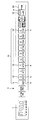
- FIG. 4 It is the external view seen from the front in the cooking-by-heating machine of this invention. It is an expansion perspective view of the operation key part in FIG. It is a block diagram which shows schematic structure of the control part in FIG. It is a figure which shows the example of a display of the original function of the operation key part in FIG. It is a figure which shows the example of a display of the function after the change of the operation key part in FIG. 4 is a flowchart of “number key function setting processing operation” executed by the CPU in FIG. 3. It is a figure which shows the example of a display of the original function of the operation key part different from FIG. 4A. It is a figure which shows the example of a display of the function after the change of the operation key part different from FIG. 4B. It is a figure which shows the example of a display different from FIG. 4B. It is a figure which shows the example of a display different from FIG. 6B.
- FIG. 1 is the external view seen from the front in the heating cooker of this Embodiment.
- the main heating cooker 1 is a commercial heating cooker used in a convenience store or the like.
- the operation key unit 3 is installed at the upper part of the front of the rectangular parallelepiped cabinet 2, and the operation key unit 3 at the front of the cabinet 2.
- a door 4 that opens and closes a heating chamber (not shown) by rotating about the left end side is provided on the lower side.
- a handle 5 is provided on the right side of the door 4, and a window 6 made of heat-resistant glass is fitted into the door 4.
- a liquid crystal display unit 7 is provided on the left side of the operation key unit 3 in the figure.
- the heating cooker 1 heats an object to be heated by microwaves generated by a magnetron.
- the heating structure of the object to be heated by the microwave is the same as that of a conventional microwave heating cooker.
- a microwave generated by a magnetron disposed under the heating chamber is guided.
- the tube is guided to the lower center of the heating chamber and radiates upward in the heating chamber while being rotated by a rotating antenna driven by a motor.
- the structure of a heating part is not specified in particular. Instead of the heating by the microwave, the structure of the heating unit that heats the object to be heated by a heater, superheated steam, or the like may be used.
- FIG. 2 is an enlarged perspective view of the operation key unit 3.
- the operation key unit 3 is configured as a horizontally long rod-like body in which a plurality of keys are arranged in the horizontal direction, and ten keys 9 to which numbers from “1” to “0” are assigned at the center. , 10 to 18 (hereinafter, the ten keys 9, 10 to 18 are collectively referred to as numeric keys 19) are arranged in a line.
- a plurality of cooking menus are assigned to each of the numeric keys 19. Then, when a certain numeric key 19 is pressed, a cooking menu is selected according to the number of times the key is pressed, and the magnetron driving unit is controlled by the control unit 8 as will be described in detail later according to the selected cooking menu.
- the heat treatment operation is performed on the object to be heated with the output power and the heating time corresponding to the selected cooking menu.
- a heating time and an output duty are set as cooking conditions. For example, when the maximum output in the heating cooker 1 is 1900 W, and the heating time “10 seconds” and the output duty “100%” are set as the cooking conditions of the selected cooking menu, Is heated at 1900 W for 10 seconds.
- the key 20 in the operation key unit 3 is a “ ⁇ 2 / ⁇ 3” key that doubles or triples the cooking time.
- the key 21 is an “Express Defrost” key dedicated to decompression.
- the key 22 is a “custom help” key for setting the volume of a speaker (not shown) that outputs a sound such as the end of cooking.
- the key 23 is a “set memory” key that sets, for example, items set by operating each key of the operation key unit 3 in the memory.
- the key 24 is a “start” key for confirming the cooking menu selected by the operation of the numeric keys 19 or for confirming and starting the cooking when the cooking conditions are set manually.
- the key 25 cancels the cooking menu selected by the operation of the numeric key 19, while the selected cooking menu is confirmed.
- it is a “Stop / Clear” key for stopping the started cooking.
- the key 26 is a “select time” key for designating a time setting when manually setting a desired heating time.
- the key 27 is a “select power” key for designating output duty setting when manually setting a desired output duty.
- a plurality of cooking menus are assigned to each of the numeric keys 19. Then, when a certain numeric key 19 is pressed, a cooking menu is selected according to the number of times the key 19 is pressed, and the magnetron driving unit is controlled by the control unit 8 according to the selected cooking menu, so that the heat treatment operation starts automatically. It has come to be.
- the cooking menu can be changed by pressing the number key 19 again before the cooking menu is confirmed by pressing the “start” key 24 or before the cooking menu is confirmed after a preset time has elapsed. It has become.
- the heating cooker 1 can also perform cooking without depending on the cooking menu assigned to each of the numeric keys 19.
- the “select time” key 26 or the “select power” key 27 is pressed.
- the assignment of the cooking menu to the keys 9 to 18 of the numeric key 19 is canceled.
- the function of the “start” key 24 is changed so as to function as a key for confirming and starting the set cooking conditions.
- the feature of the present embodiment is that the function of each key 9 to 18 in the numeric key 19 shown in FIG. 2 is changed after the cooking menu selected by the numeric key 19 or the manually set cooking condition is determined.
- the function is changed from the original function as a numeric input key to the function of a halfway stop key of the cooking operation.
- the function switching of the numeric keys 19 is performed by the control unit 8 as will be described in detail later.
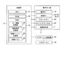
- FIG. 3 is a block diagram showing a schematic configuration in the control unit 8 of the heating cooker 1 having the above configuration.
- the control unit 8 includes a CPU (Central Processing Unit) 31, a ROM (Read Only Memory) 32, and a RAM (Random Access Memory) 33.
- the ROM 32 stores a cooking program for the CPU 31 to perform cooking using various cooking menus.
- the RAM 33 stores work data and reference data that is referred to when a cooking menu is selected, when the function of the numeric key 19 is set, or when cooking is performed.
- the control unit 8 is driven by the numeric key 19, various keys 20 to 23, 26, 27, a “start” key 24, a “stop / clear” key 25, a liquid crystal display unit 7, and a magnetron 35.
- a magnetron driving unit 34 is connected.
- a device such as a temperature sensor is connected.
- the CPU 31 refers to the reference data stored in the RAM 33 and selects the cooking menu designated by the user. Then, according to the cooking program stored in the ROM 32, the input data input from each device and the reference data stored in the RAM 33 are referred to, and the cooking process of the selected cooking menu and the binary for the various data are stored. Performs arithmetic processing such as addition, logical operation, and comparison.
- the CPU 31 stores in the RAM 33 that “the power is turned on”, “the selected cooking menu or manually set cooking conditions are determined”, and “the cooking is finished”.
- the function of the numeric key 19 in the operation key unit 3 is set, and the notation of the numeric key 19 is set to the notation representing the set function.
- the function of the numeric key 19 is stored as an index as a storage area for reference data that is referenced when the power is turned on, when the cooking menu and cooking conditions are confirmed, and when cooking is completed.
- a key function storage unit 36 is provided for storing the heat cooking device 1 in association with the operation state thereof.
- a function notation storage unit 37 is provided for storing the notation of the function of the numeric key 19 stored in the key function storage unit 36 in association with the function of each key.
- the RAM 33 is provided with a cooking menu storage unit 38 for storing the cooking menu in association with the numeric keys 19 as a storage area for reference data to be referred to when the cooking menu is selected and when the cooking process is performed. ing. Furthermore, a work memory 39 is provided in which data to be referred to when executing the cooking process is temporarily stored. Here, the work memory 39 includes a flag for recording the operating state of the main heating cooker 1.
- cooking by the cooking menu selected with reference to the cooking menu storage unit 38 may be referred to as memory cooking.
- cooking under the above cooking conditions set manually with the numeric keys 19 may be referred to as manual cooking.
- the CPU 31 refers to the key function storage unit 36 of the RAM 33 and refers to the keys 9 to 18 of the number key 19 when the operation state of the heating cooker 1 is “power on”. Get the initial function "Numeric input”. Further, referring to the function notation storage unit 37 of the RAM 33, a notation representing the initial function “number input” of each key 9 to 18 is obtained. As shown in FIG. 4A, the numbers “1” to “0” representing the original function “number input” of each key 9 to 18 are displayed on the display screen provided on the surface of each key 9 to 18. .
- the operation state of the cooking device 1 is referred to by referring to the key function storage unit 36 of the RAM 33.
- the function “stop cooking operation” of each of the keys 9 to 18 of the numeric key 19 is obtained.
- the function notation storage unit 37 of the RAM 33 a notation representing the function “stop cooking operation” after the change of each key 9 to 18 is obtained.
- the notation “1 / STOP” to “0 / STOP” indicating the changed function “stop cooking operation” is displayed by switching to the display screen of each key 9-18. .
- each key 9-18 of the numeric key 19 returns to the initial function, and the display of each key 9-18 also returns to the notation indicating the initial function.
- each key of the operation key unit 3 constitutes the operation unit of the claims
- the display screen of the operation key unit 3 constitutes the display unit of the claims.
- the CPU 31 constitutes the heating control means, the operation unit function changing means, and the display changing means of the claims.
- the display switching of the notation indicating the function of the numeric keys 19 on the display screens of the keys 9 to 18 can be performed by making at least the display screens of the keys 9 to 18 into liquid crystal display screens.
- FIG. 5 is a flowchart of the “number key function setting processing operation” executed by the CPU 31. A brief description is given below.
- the “numeric key function setting processing operation” starts.
- step S1 the operation state recording flag of the work memory 39 in the RAM 33 and the key function storage unit 36 are referred to, and the initial function “number input” in the “power-on” state of each of the keys 9 to 18 of the number key 19 is referred to. Is obtained.
- step S2 the function notation storage unit 37 of the RAM 33 is referred to, and a notation representing the initial function “number input” of each key 9 to 18 is obtained. Then, numbers “1” to “0” representing the initial function “number input” are displayed on the display screens of the keys 9 to 18. The flag is set according to the operation state of the heating cooker 1 during “cooking menu selection and heating processing operation” executed separately from the “number key function setting processing operation” by the CPU 31. Written.
- step S3 it is determined whether or not the numeric key 19 has been operated. As a result, when operated, the process proceeds to step S4.
- step S4 the flag in the work memory 39 is referred to, and it is determined whether or not the operation of the numeric key 19 in step S3 is the designation of the cooking menu during the memory heating cooking. As a result, if it is the memory heating cooking, the process proceeds to step S5, and if it is not the memory heating cooking (that is, if the cooking conditions are input during manual heating cooking), the process proceeds to step S6.
- step S5 it is determined whether or not the preset set time has elapsed since the memory heating cooking was started, using a timer (not shown) built in the controller 8 or the like. Is done. As a result, if it has elapsed, the cooking menu for the above-mentioned memory heating cooking has been determined, and the process proceeds to step S7. If not, the process proceeds to step S6. In step S6, it is determined whether or not the start key 24 has been operated. As a result, if it has been operated, the cooking menu for the above-mentioned memory heating cooking or the above-mentioned cooking conditions for the above-mentioned manual heating cooking has been determined, and the process proceeds to step S7.
- step S 7 the flag and key function storage unit 36 of the work memory 39 in the RAM 33 is referred to, and the function of each key 9 to 18 in the numeric key 19 is the function “when the cooking menu or cooking condition is determined”. It is changed to “stop cooking operation”. Further, in step S8, the function notation storage unit 37 of the RAM 33 is referred to, and a notation representing the function “stop cooking operation” of each key 9 to 18 is obtained. The display on the display screen of each key 9 to 18 is changed to notation “1 / STOP” to “0 / STOP” representing the function “stop cooking operation”.
- step S9 the flag in the work memory 39 is referred to, and it is determined whether or not the memory heating cooking or the manual heating cooking determined in step S6 is completed. As a result, if it has been completed, the process proceeds to step S10.
- step S10 the flag and key function storage unit 36 of the work memory 39 in the RAM 33 is referred to, and the function “number input” when the functions of the keys 9 to 18 of the number key 19 are in the “end cooking” state.
- step S11 the function notation storage unit 37 of the RAM 33 is referred to, and a notation representing the function “number input” of each key 9 to 18 is obtained. Then, the display on the display screen of the keys 9 to 18 is changed to numbers “1” to “0” representing the function “number input”.
- the numeric key function setting processing operation is terminated.
- the function of the numeric key 19 is activated.
- the keys 9 to 18 are switched to display the notations “1 / STOP” to “0 / STOP” representing the function “stop cooking operation”.
- the same character “STOP” is displayed on the surface of all the keys 9 to 18 in the numeric key 19.
- the present invention is not limited to this, and it is possible to assign a different language representing “STOP” to each of the keys 9 to 18.
- Key 9... “1 / stop” Japanese
- Key 10 ... “2 / STOP” (English) :... “3 / ARRE ⁇ T” (French) Key 12... “4 / HALT” (German) :... “5 / FERMATA” (Italian) : “6 / PARADA” (Spanish) : ...: It is assigned as follows. In this way, it is possible to display in 10 different languages, which is particularly effective in Europe, which is a multilingual area.
- the present invention will be described with respect to function setting and function display for each key, taking as an example the heating cooker 1 having the operation key unit 3 installed at the upper front of the cabinet 2. ing.
- the configuration of the operation key unit is not limited to the configuration of the operation key unit 3.
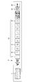
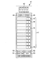
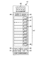
- FIGS. 6A and 6B show an example of the operation key unit 41 installed on the right or left side of the front of a rectangular parallelepiped cabinet as a modification of the present embodiment.
- the operation key unit 41 has the same function as the operation key unit 3 in the above-described embodiment except that the keys are mainly arranged vertically.
- the operation key unit 41 is entirely written in English, assuming use in Europe.
- a liquid crystal display section 42 is provided on the upper side of the operation key section 41 in the figure.
- the liquid crystal display unit 42 corresponds to the liquid crystal display unit 7 in the operation key unit 3.
- ten keys 43, 44 to 46 (hereinafter, the ten keys 43, 44 to 46 are collectively referred to as numbers assigned from “1” to “0”) in the central portion of the operation key unit 41. Number keys 47) are arranged in a line.
- the keys 43, 44 to 46 and the numeric key 47 correspond to the keys 9, 10 to 18 and the numeric key 19 in the operation key unit 3.
- the “double-quantity” key 48 in the operation key section 41 corresponds to the “ ⁇ 2 / ⁇ 3” key 20 in the operation key section 3.
- the “express defrost” key 49 corresponds to the “express defrost” key 21 in the operation key unit 3.
- the “select time” key 50 corresponds to the “select time” key 26 in the operation key unit 3.
- the “select power” key 51 corresponds to the “select power” key 27 in the operation key unit 3.
- the “stop / clear” key 52 corresponds to the “stop / clear” key 25 in the operation key unit 3. This corresponds to the “start” key 53 and the “start” key 24 in the operation key unit 3.
- FIG. 6A shows a state in which numbers “1” to “0” representing the function “number input” are displayed on the surfaces of the keys 43 to 46.
- FIG. 6B shows a state where the notations “1 / STOP” to “0 / STOP” representing the function “stop cooking operation” are displayed on the surfaces of the keys 43 to 46.
- “1 / STOP” to “0 / STOP” are used as notations representing the function “stop cooking operation”, but the selected cooking is displayed when this notation is displayed.
- the cooking conditions set in the menu or manually are fixed, and the numeric keys 19, 47 do not have a numeric input function. Therefore, “STOP” may be used as a notation representing the function “stop cooking operation”.
- the cooking menu is selected according to the frequency
- This embodiment can cope with an abnormality before the operation state of the cooking device becomes “confirmation of cooking menu”.
- the configuration and processing operation of the heating cooker in the present embodiment are the same as those of the heating cooker 1 in the first embodiment. Then, the same number is attached
- FIG. 7A and 7B show display examples of the operation key unit when the operation state of the cooking device according to the present embodiment is “start of memory cooking”.
- FIG. 7A is the same operation key part as FIG. 2 installed in the upper part of the front of the cabinet.
- this operation key part is referred to as an operation key part 3.
- FIG. 7B is the same operation key part as FIG. 6A and B installed in the right side or the left side of the front of a cabinet.
- this operation key part is referred to as an operation key part 41.
- the display in the notation indicating the initial function is the same as in the case of the first embodiment (FIGS. 4A and 6A).
- a stop lamp a is provided in the “STOP” display area of the “Stop / Clear” keys 25 and 52, while each of the keys 9 to 18 of the numeric keys 19 and 47 is provided.
- 43 to 46 are provided with a stop lamp b in the “STOP” display area. When the stop lamp a or the stop lamp b is lit, the lit key functions as a “stop cooking operation” key.
- the display operation of each key is different between the case of the “memory heating cooking” and the case of the “manual heating cooking”.
- the stop lamps b of the keys 9 to 18 of the number key 19 are also turned on.
- the numeric key 19 also displays that it functions as a “stop cooking operation” key.
- the stop lamps a and b constitute the display section of the claims.
- the stop lamp a of the “Stop / Clear” keys 25 and 52 and the stop lamp b of the keys 9 to 18 and 43 to 46 of the numeric keys 19 and 47 are formed on the liquid crystal display screen formed on the surface of each key. It may be composed of one display area provided in the LED, or may be composed of an LED (light emitting diode) lamp embedded in the liquid crystal display screen.
- the stop lamp a in the “STOP” display area of each key is used so that the key functioning as the “stop cooking operation” key can be seen at a glance.
- b is provided.
- the present invention is not limited to this, by blinking the ground portion of the function display surface of the key functioning as the “stop cooking operation” key or changing the ground color. It may be emphasized that it functions as a “stop cooking operation” key.
- the “stop cooking operation” function is provided only on the numeric keys 19, 47. It is trying to have.
- the present invention is not limited to the numeric keys 19 and 47, and other keys and all keys except the “start” keys 24 and 53 and the “stop / clear” keys 25 and 52 have “heating”. Even if it has a function of “stop cooking operation”, there is no problem.
- any key that is not operated after the cooking menu or the cooking conditions are determined can have a “stop cooking operation” function. In that case, it is desirable to change the function of more than half of the plurality of keys to the “stop cooking operation” function.
- the heat treatment operation is automatically started. If the cooking menu is not confirmed by pressing, the heat treatment operation may not be started. In this case, when the heat treatment operation is started by pressing the “start” keys 24 and 53, the functions of the keys 9 to 18 and 43 to 46 of the numeric keys 19 and 47 are set to “stop cooking operation”. It is necessary to change to.
- the operation unit is constituted by each of a plurality of keys provided in the operation key units 3 and 41.
- the present invention is not limited to this, and may be configured by a push button having a display unit on the surface or individual touch units of the touch panel.
Landscapes
- Engineering & Computer Science (AREA)
- Physics & Mathematics (AREA)
- Electromagnetism (AREA)
- Human Computer Interaction (AREA)
- Chemical & Material Sciences (AREA)
- Combustion & Propulsion (AREA)
- Mechanical Engineering (AREA)
- General Engineering & Computer Science (AREA)
- Electric Ovens (AREA)
Abstract
La présente invention concerne un dispositif de cuisson par chauffage. Lorsque la cuisson par chauffage commence et que le menu de cuisson ou les conditions de cuisson ont été définis, les fonctions des touches numériques (19) changent en «arrêt de l'opération de cuisson par chauffage» et les signes «1/STOP» - «0/STOP» indiquant la fonction «arrêt de l'opération de cuisson par chauffage» sont affichés à la place sur chaque touche (9-18). En conséquence, toute personne capable de comprendre la signification du mot anglais «STOP», très couramment utilisé partout dans le monde, peut comprendre en un coup d'œil que chaque touche (9-18) fonctionne comme touche «arrêt de l'opération de cuisson par chauffage». Ainsi, même des travailleurs temporaires, à temps partiel ou étrangers, qui ne connaissent pas bien le fonctionnement du dispositif de cuisson par chauffage, peuvent arrêter facilement et de manière fiable l'opération de chauffage lorsqu'un problème survient pendant la cuisson.
Applications Claiming Priority (2)
| Application Number | Priority Date | Filing Date | Title |
|---|---|---|---|
| JP2011-167183 | 2011-07-29 | ||
| JP2011167183A JP2013029287A (ja) | 2011-07-29 | 2011-07-29 | 加熱調理器 |
Publications (1)
| Publication Number | Publication Date |
|---|---|
| WO2013018718A1 true WO2013018718A1 (fr) | 2013-02-07 |
Family
ID=47629241
Family Applications (1)
| Application Number | Title | Priority Date | Filing Date |
|---|---|---|---|
| PCT/JP2012/069213 Ceased WO2013018718A1 (fr) | 2011-07-29 | 2012-07-27 | Dispositif de cuisson par chauffage |
Country Status (2)
| Country | Link |
|---|---|
| JP (1) | JP2013029287A (fr) |
| WO (1) | WO2013018718A1 (fr) |
Cited By (1)
| Publication number | Priority date | Publication date | Assignee | Title |
|---|---|---|---|---|
| CN111035221A (zh) * | 2018-10-11 | 2020-04-21 | 夏普株式会社 | 操作显示装置、烹调器 |
Citations (4)
| Publication number | Priority date | Publication date | Assignee | Title |
|---|---|---|---|---|
| JP2000140045A (ja) * | 1998-11-06 | 2000-05-23 | Osada Res Inst Ltd | 歯科治療椅子 |
| JP2009146631A (ja) * | 2007-12-12 | 2009-07-02 | Panasonic Corp | 電気機器 |
| JP2009243773A (ja) * | 2008-03-31 | 2009-10-22 | Panasonic Corp | 加熱調理器 |
| JP2011033312A (ja) * | 2009-08-05 | 2011-02-17 | Mitsubishi Electric Corp | 加熱調理器 |
Family Cites Families (1)
| Publication number | Priority date | Publication date | Assignee | Title |
|---|---|---|---|---|
| JP4772068B2 (ja) * | 2008-01-30 | 2011-09-14 | シャープ株式会社 | 業務用の加熱調理器 |
-
2011
- 2011-07-29 JP JP2011167183A patent/JP2013029287A/ja active Pending
-
2012
- 2012-07-27 WO PCT/JP2012/069213 patent/WO2013018718A1/fr not_active Ceased
Patent Citations (4)
| Publication number | Priority date | Publication date | Assignee | Title |
|---|---|---|---|---|
| JP2000140045A (ja) * | 1998-11-06 | 2000-05-23 | Osada Res Inst Ltd | 歯科治療椅子 |
| JP2009146631A (ja) * | 2007-12-12 | 2009-07-02 | Panasonic Corp | 電気機器 |
| JP2009243773A (ja) * | 2008-03-31 | 2009-10-22 | Panasonic Corp | 加熱調理器 |
| JP2011033312A (ja) * | 2009-08-05 | 2011-02-17 | Mitsubishi Electric Corp | 加熱調理器 |
Cited By (2)
| Publication number | Priority date | Publication date | Assignee | Title |
|---|---|---|---|---|
| CN111035221A (zh) * | 2018-10-11 | 2020-04-21 | 夏普株式会社 | 操作显示装置、烹调器 |
| CN111035221B (zh) * | 2018-10-11 | 2022-02-11 | 夏普株式会社 | 操作显示装置、烹调器 |
Also Published As
| Publication number | Publication date |
|---|---|
| JP2013029287A (ja) | 2013-02-07 |
Similar Documents
| Publication | Publication Date | Title |
|---|---|---|
| US6750433B2 (en) | Oven display and user interface | |
| US8314370B2 (en) | Cooking device | |
| RU2355062C2 (ru) | Электроприбор с панелью управления | |
| JP6341825B2 (ja) | 加熱調理器 | |
| CN102345883A (zh) | 加热烹调器 | |
| JP2013029287A (ja) | 加熱調理器 | |
| JP4722059B2 (ja) | 加熱調理器及び炊飯器 | |
| JP5159870B2 (ja) | 加熱調理器 | |
| JP6549530B2 (ja) | 調理器 | |
| JP5558239B2 (ja) | 誘導加熱調理器 | |
| JP3985765B2 (ja) | 加熱調理器 | |
| JP4646841B2 (ja) | 加熱調理器 | |
| JP4309903B2 (ja) | 加熱調理器 | |
| JP6694585B2 (ja) | 炊飯器 | |
| JPS59191817A (ja) | 調理器具 | |
| JP5082381B2 (ja) | 加熱装置 | |
| CA2860954C (fr) | Four de cuisson ou four de pressee | |
| JP2005265237A (ja) | 電子レンジ | |
| JP6674234B2 (ja) | 食器洗浄機 | |
| JP3791603B2 (ja) | 加熱調理器 | |
| JP5769571B2 (ja) | 加熱調理器 | |
| JP2020038017A (ja) | 加熱調理器 | |
| JP2022182223A (ja) | 加熱調理器 | |
| JP2021071231A (ja) | スチームコンベクションオーブン | |
| KR0159748B1 (ko) | 가열조리기 |
Legal Events
| Date | Code | Title | Description |
|---|---|---|---|
| 121 | Ep: the epo has been informed by wipo that ep was designated in this application |
Ref document number: 12819557 Country of ref document: EP Kind code of ref document: A1 |
|
| NENP | Non-entry into the national phase |
Ref country code: DE |
|
| 122 | Ep: pct application non-entry in european phase |
Ref document number: 12819557 Country of ref document: EP Kind code of ref document: A1 |