WO2013021925A1 - Dispositif d'accumulation, agrégat de dispositifs d'accumulation et procédé de fabrication du dispositif d'accumulation - Google Patents
Dispositif d'accumulation, agrégat de dispositifs d'accumulation et procédé de fabrication du dispositif d'accumulation Download PDFInfo
- Publication number
- WO2013021925A1 WO2013021925A1 PCT/JP2012/069763 JP2012069763W WO2013021925A1 WO 2013021925 A1 WO2013021925 A1 WO 2013021925A1 JP 2012069763 W JP2012069763 W JP 2012069763W WO 2013021925 A1 WO2013021925 A1 WO 2013021925A1
- Authority
- WO
- WIPO (PCT)
- Prior art keywords
- power storage
- storage cell
- terminal
- polar body
- storage device
- Prior art date
- Legal status (The legal status is an assumption and is not a legal conclusion. Google has not performed a legal analysis and makes no representation as to the accuracy of the status listed.)
- Ceased
Links
Images














Classifications
-
- H—ELECTRICITY
- H01—ELECTRIC ELEMENTS
- H01G—CAPACITORS; CAPACITORS, RECTIFIERS, DETECTORS, SWITCHING DEVICES, LIGHT-SENSITIVE OR TEMPERATURE-SENSITIVE DEVICES OF THE ELECTROLYTIC TYPE
- H01G11/00—Hybrid capacitors, i.e. capacitors having different positive and negative electrodes; Electric double-layer [EDL] capacitors; Processes for the manufacture thereof or of parts thereof
- H01G11/74—Terminals, e.g. extensions of current collectors
- H01G11/76—Terminals, e.g. extensions of current collectors specially adapted for integration in multiple or stacked hybrid or EDL capacitors
-
- H—ELECTRICITY
- H01—ELECTRIC ELEMENTS
- H01M—PROCESSES OR MEANS, e.g. BATTERIES, FOR THE DIRECT CONVERSION OF CHEMICAL ENERGY INTO ELECTRICAL ENERGY
- H01M50/00—Constructional details or processes of manufacture of the non-active parts of electrochemical cells other than fuel cells, e.g. hybrid cells
- H01M50/20—Mountings; Secondary casings or frames; Racks, modules or packs; Suspension devices; Shock absorbers; Transport or carrying devices; Holders
- H01M50/249—Mountings; Secondary casings or frames; Racks, modules or packs; Suspension devices; Shock absorbers; Transport or carrying devices; Holders specially adapted for aircraft or vehicles, e.g. cars or trains
-
- H—ELECTRICITY
- H01—ELECTRIC ELEMENTS
- H01G—CAPACITORS; CAPACITORS, RECTIFIERS, DETECTORS, SWITCHING DEVICES, LIGHT-SENSITIVE OR TEMPERATURE-SENSITIVE DEVICES OF THE ELECTROLYTIC TYPE
- H01G11/00—Hybrid capacitors, i.e. capacitors having different positive and negative electrodes; Electric double-layer [EDL] capacitors; Processes for the manufacture thereof or of parts thereof
- H01G11/78—Cases; Housings; Encapsulations; Mountings
- H01G11/82—Fixing or assembling a capacitive element in a housing, e.g. mounting electrodes, current collectors or terminals in containers or encapsulations
-
- H—ELECTRICITY
- H01—ELECTRIC ELEMENTS
- H01M—PROCESSES OR MEANS, e.g. BATTERIES, FOR THE DIRECT CONVERSION OF CHEMICAL ENERGY INTO ELECTRICAL ENERGY
- H01M50/00—Constructional details or processes of manufacture of the non-active parts of electrochemical cells other than fuel cells, e.g. hybrid cells
- H01M50/20—Mountings; Secondary casings or frames; Racks, modules or packs; Suspension devices; Shock absorbers; Transport or carrying devices; Holders
- H01M50/204—Racks, modules or packs for multiple batteries or multiple cells
- H01M50/207—Racks, modules or packs for multiple batteries or multiple cells characterised by their shape
- H01M50/209—Racks, modules or packs for multiple batteries or multiple cells characterised by their shape adapted for prismatic or rectangular cells
-
- H—ELECTRICITY
- H01—ELECTRIC ELEMENTS
- H01M—PROCESSES OR MEANS, e.g. BATTERIES, FOR THE DIRECT CONVERSION OF CHEMICAL ENERGY INTO ELECTRICAL ENERGY
- H01M50/00—Constructional details or processes of manufacture of the non-active parts of electrochemical cells other than fuel cells, e.g. hybrid cells
- H01M50/20—Mountings; Secondary casings or frames; Racks, modules or packs; Suspension devices; Shock absorbers; Transport or carrying devices; Holders
- H01M50/271—Lids or covers for the racks or secondary casings
-
- H—ELECTRICITY
- H01—ELECTRIC ELEMENTS
- H01M—PROCESSES OR MEANS, e.g. BATTERIES, FOR THE DIRECT CONVERSION OF CHEMICAL ENERGY INTO ELECTRICAL ENERGY
- H01M50/00—Constructional details or processes of manufacture of the non-active parts of electrochemical cells other than fuel cells, e.g. hybrid cells
- H01M50/20—Mountings; Secondary casings or frames; Racks, modules or packs; Suspension devices; Shock absorbers; Transport or carrying devices; Holders
- H01M50/296—Mountings; Secondary casings or frames; Racks, modules or packs; Suspension devices; Shock absorbers; Transport or carrying devices; Holders characterised by terminals of battery packs
-
- Y—GENERAL TAGGING OF NEW TECHNOLOGICAL DEVELOPMENTS; GENERAL TAGGING OF CROSS-SECTIONAL TECHNOLOGIES SPANNING OVER SEVERAL SECTIONS OF THE IPC; TECHNICAL SUBJECTS COVERED BY FORMER USPC CROSS-REFERENCE ART COLLECTIONS [XRACs] AND DIGESTS
- Y02—TECHNOLOGIES OR APPLICATIONS FOR MITIGATION OR ADAPTATION AGAINST CLIMATE CHANGE
- Y02E—REDUCTION OF GREENHOUSE GAS [GHG] EMISSIONS, RELATED TO ENERGY GENERATION, TRANSMISSION OR DISTRIBUTION
- Y02E60/00—Enabling technologies; Technologies with a potential or indirect contribution to GHG emissions mitigation
- Y02E60/10—Energy storage using batteries
Definitions
- the present invention relates to a power storage device that can be charged and discharged, a power storage device assembly, and a method for manufacturing the power storage device.
- an electric double layer capacitor As electric storage devices that can charge and discharge electricity, an electric double layer capacitor, a secondary battery, and the like are known.
- an electric double layer capacitor what was described in patent document 1 is known, for example.
- a secondary battery what was described in patent document 2, for example is known.
- a plurality of power storage devices may be connected in series to be used as a power storage device aggregate in order to secure a necessary voltage.
- An object of the present invention is to simplify connection work when a plurality of power storage devices are connected to form a power storage device assembly.
- the present invention includes a first electricity storage cell and a second electricity storage cell having a first electrode body and a second electrode body, which are chargeable / dischargeable, and a first storage chamber and the second electricity storage device for housing the first electricity storage cell.
- a conductor housing having a second storage chamber for storing a cell and electrically connecting the first polar body of the first power storage cell and the first polar body of the second power storage cell;
- a first terminal electrically connected to the second polar body of one storage cell and drawn out of the casing; and an external connection of the second terminal of the second storage cell to the outside of the casing And a second terminal drawn out to the power storage device.
- a partition member that partitions the space enclosed by the housing into the first storage chamber and the second storage chamber.
- the first terminal and the second terminal have a lead portion for electrically connecting the first polar body of the first storage cell and the first polar body of the second storage cell. It is preferable to arrange in the same direction as the direction extending from the first polar body of one power storage cell and the first polar body of the second power storage cell.
- the first terminal and the second terminal have a lead portion for electrically connecting the first polar body of the first storage cell and the first polar body of the second storage cell. It is preferable that the first electrode body is pulled out in a direction opposite to the direction extending from the first electrode body of the first storage cell and the first electrode body of the second storage cell.
- the housing includes a cylindrical side peripheral member and a pair of end side members respectively provided at both ends of the side peripheral member.
- one of the end side members is formed integrally with the side peripheral member, and the first pole body of the first storage cell and the first pole body of the second storage cell are the other end portion. It is preferable that the first terminal and the second terminal are pulled out from the other end side member while being electrically connected to the side member.
- the pair of end side members are joined to both ends of the side circumferential member, respectively, and the first pole body of the first storage cell and the first pole body of the second storage cell are one Preferably, the first terminal and the second terminal are pulled out from the other end side member.
- the partition member is a conductor, and the first pole body of the first storage cell, the first pole body of the second storage cell, and the housing are electrically connected to the partition member. It is preferable.
- the first terminal and the second terminal are arranged in a direction parallel to a direction in which the first electricity storage cell and the second electricity storage cell are arranged.
- the end side member from which the first terminal and the second terminal are not taken out has an attachment portion for attaching the housing to an attachment target.
- the present invention is a power storage device assembly in which a plurality of the power storage devices are connected in series.
- the present invention provides a procedure for storing a chargeable / dischargeable first storage cell and a second storage cell in a first storage chamber and a second storage chamber of a casing, respectively, and a lid attached to the casing.
- the first polar body of one power storage cell and the first polar body of the second power storage cell are electrically connected, and the second polar body of the first power storage cell is connected to a first terminal provided on the lid. Electrically connected, and further, a procedure for electrically connecting the second polar body of the second storage cell to a second terminal provided on the lid, and attaching the lid to the casing for sealing
- a method for manufacturing a power storage device A method for manufacturing a power storage device.
- the present invention provides a procedure for electrically connecting a first polar body of a chargeable / dischargeable first storage cell and a first polar body of a chargeable / dischargeable second storage cell to a member serving as a bottom portion of a housing; A procedure for storing the first storage cell in a first storage chamber of the housing and storing the second storage cell in a second storage chamber of the housing; and a member serving as the bottom portion.
- the step of joining to the housing, the second electrode body of the first storage cell is electrically connected to the first terminal provided on the lid attached to the housing, and the second provided on the lid
- a method for manufacturing a power storage device comprising: a step of electrically connecting a second polar body of the second power storage cell to a terminal; and a step of attaching and sealing the lid to the housing. .
- the present invention provides a procedure for arranging chargeable / dischargeable first storage cells and second cells on both surfaces of a plate-like partition member via an insulator, and a first polar body of the first storage cell. And the first electrode body of the second electricity storage cell are electrically connected to the partition member, the second electrode body of the first electricity storage cell is electrically connected to a first terminal, and A procedure for electrically connecting the second polar body of the two energy storage cells to the second terminal, and a part of the first energy storage cell, the second energy storage cell, the first terminal, and the second terminal in the housing 3 A method for manufacturing the power storage device.
- the present invention can simplify the connection work when a plurality of power storage devices are connected to form a power storage device assembly.
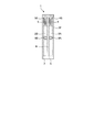
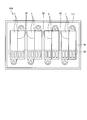
- FIG. 1 is a front view illustrating the power storage device according to the first embodiment.
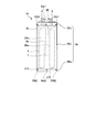
- FIG. 2 is a side view showing the power storage device according to the first embodiment.
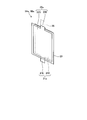
- FIG. 3 is a plan view illustrating the power storage device according to the first embodiment.
- FIG. 4 is a perspective view of the first polar body, the second polar body, and the separator.
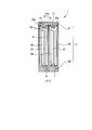
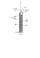
- FIG. 5 is a cross-sectional view taken along the line AA in FIG. 6 is a cross-sectional view taken along the line BB of FIG.
- FIG. 7 is a plan view showing a first power storage cell and a second power storage cell included in the power storage device according to the present embodiment.
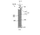
- FIG. 8A is a cross-sectional view taken along the line CC of FIG. FIG.
- FIG. 8-2 is an enlarged view showing a modified example of the connection structure of the first lead portion.
- FIG. 9A is a sectional view taken along the line DD of FIG.
- FIG. 9-2 is an enlarged view showing a modification of the connection structure of the second lead portion.
- FIG. 10 is an electric circuit diagram of a power storage device in which single power storage cells are connected in series.
- FIG. 11 is an electric circuit diagram of the power storage device according to the first embodiment.
- FIG. 12 is a diagram illustrating the method for manufacturing the power storage device according to the first embodiment.
- FIG. 13 is a diagram illustrating the method for manufacturing the power storage device according to the first embodiment.
- FIG. 14 is a diagram illustrating a method for manufacturing the power storage device according to the first embodiment.
- FIG. 15 is a diagram illustrating the method for manufacturing the power storage device according to the first embodiment.
- FIG. 16 is a diagram illustrating the method for manufacturing the power storage device according to the first embodiment.
- FIG. 17 is a diagram illustrating an example in which a plurality of power storage devices according to Embodiment 1 are connected in series.
- FIG. 18 is a diagram illustrating an example in which a plurality of power storage devices according to Embodiment 1 are connected in series.
- FIG. 19 is a diagram illustrating an example in which a plurality of single power storage cells illustrated in FIG. 10 are connected in series.
- FIG. 20A is a diagram illustrating an example in which a plurality of single power storage cells illustrated in FIG. 10 are connected in series.
- FIG. 20-2 is a diagram illustrating a housing of the power storage device according to the present embodiment.
- FIG. 20C is a diagram illustrating an example in which two single storage cells illustrated in FIG. 10 are connected in series.
- FIG. 21 is a diagram illustrating an example of the mounting structure of the power storage device according to the present embodiment.
- FIG. 22 is a diagram illustrating an example of the mounting structure of the power storage device according to the present embodiment.
- FIG. 23 is a diagram illustrating another example of the mounting structure of the power storage device according to the present embodiment.
- FIG. 24 is a plan view showing a power storage device assembly including a plurality of power storage devices according to the present embodiment.
- FIG. 25 is a plan view showing a power storage device assembly including a plurality of power storage devices according to the present embodiment.
- FIG. 26 is a plan view showing a power storage device assembly including a plurality of power storage devices according to the present embodiment.
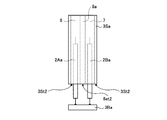
- FIG. 27 is a diagram illustrating the power storage device according to the second embodiment.
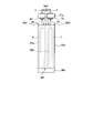
- FIG. 28 is a side view illustrating the power storage device according to the second embodiment.
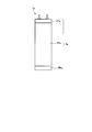
- FIG. 29 is a plan view illustrating the power storage device according to the second embodiment.
- FIG. 30 is a perspective view illustrating a first power storage cell and a second power storage cell included in the power storage device according to the second embodiment.
- FIG. 31 is a diagram illustrating a method for manufacturing the power storage device according to the second embodiment.
- FIG. 32 is a diagram illustrating a method for manufacturing the power storage device according to the second embodiment.
- FIG. 33 is a diagram illustrating a method for manufacturing the power storage device according to the second embodiment.
- FIG. 34 is a diagram illustrating a method for manufacturing the power storage device according to the second embodiment.
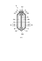
- FIG. 35 is a diagram illustrating the power storage device according to the third embodiment.
- 36 is a cross-sectional view taken along the line EE of FIG.
- FIG. 37 is a diagram illustrating the method for manufacturing the power storage device according to the third embodiment.
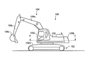
- FIG. 38 is a side view showing a hybrid excavator.
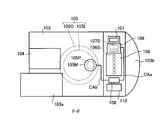
- FIG. 39 is a view taken along the line FF of FIG.
- FIG. 1 is a front view illustrating the power storage device according to the first embodiment.
- FIG. 2 is a side view showing the power storage device according to the first embodiment.
- FIG. 3 is a plan view illustrating the power storage device according to the first embodiment.
- FIG. 4 is a perspective view of the first polar body, the second polar body, and the separator.
- FIG. 5 is a cross-sectional view taken along the line AA in FIG. 6 is a cross-sectional view taken along the line BB of FIG.
- the power storage device 1 is an EDLC (Electric Double Layer Capacitor).
- the power storage device 1 is not limited to EDLC, and may be a secondary battery such as a lithium ion capacitor, an electrolytic capacitor, or a lithium ion battery.
- the power storage device 1 includes a first power storage cell 2 ⁇ / b> A and a second power storage cell 2 ⁇ / b> B, a housing 3, a first terminal 4, and a second terminal 5. Both the first storage cell 2A and the second storage cell 2B have the same structure.
- the first electricity storage cell 2A and the second electricity storage cell 2B include a first electrode body 21 (see FIG. 3) having an active material layer provided on the surface and a second electrode body having an active material layer provided on the surface. 22 (see FIG. 3). Both the first polar body 21 and the second polar body 22 are conductors.
- a separator 23 is sandwiched between the first polar body 21 and the second polar body 22. The active material of the first polar body 21 and the active material of the second polar body 22 are opposed to the separator 23.
- the first polar body 21 and the second polar body 22 are immersed in the electrolyte together with the separator 23 and the active material provided on the respective surfaces.
- the active material layers provided on the surface of the first polar body 21 and the surface of the second polar body 22 form a first polarizable electrode 24A and a second polarizable electrode 24B, respectively.
- both the first polar body 21 and the second polar body 22 form an electric double layer capacitor. That is, the first polar body 21, the second polar body 22, and the separator 24 constitute an EDLC.
- the first power storage cell 2 ⁇ / b> A and the second power storage cell 2 ⁇ / b> B have at least one combination of the first electrode body 21, the second electrode body 22, and the separator 24.
- the first storage cell 2A and the second storage cell 2B have a plurality of the combinations.
- each of the first power storage cell 2A and the second power storage cell 2B is an EDLC and is a chargeable / dischargeable power storage element.
- the structures of the first storage cell 2A and the second storage cell 2B and the structures of the first electrode body 21 and the second electrode body 22 will be described in detail later.
- the housing 3 has a first storage chamber 6 for storing the first storage cell 2A and a second storage chamber 7 for storing the second storage cell 2B. Moreover, the housing
- casing 3 is made from the conductor, and the 1st polar body 21 of a 1st electrical storage cell and the 1st polar body 21 of a 2nd electrical storage cell are electrically connected.
- the housing 3 is a structure for partitioning the first power storage cell 2A and the second power storage cell 2B from the outside.
- the housing 3 includes a side circumferential member 3S, a lid 3T, and a bottom 3B. For this reason, the side peripheral member 3S, the lid 3T, and the bottom 3B are conductors.
- the housing 3 is, for example, an aluminum alloy, but the material of the housing 3 is not limited to this.
- the side circumferential member 3S, the lid 3T, and the bottom 3B may be all conductors, and the materials may be different as necessary.
- the side circumferential member 3S and the bottom 3B may be made of an aluminum alloy, and the lid 3T may be made of a copper alloy.
- the side circumferential member 3S is a cylindrical member.
- the side circumferential member 3S has a partition member 8 in a space surrounded by side portions.
- the partition member 8 partitions the space inside the side circumferential member 3S into two spaces.
- the side circumferential member 3S and the partition member 8 are integrally formed, but both may be manufactured as separate members and joined together by joining means such as welding. Since the partition member 8 also has a function as a rib of the side peripheral member 3S of the housing 3, the strength of the side peripheral member 3S can be improved. It is preferable that the partition member 8 is fixed to the side peripheral member 3S because the function as the rib is further increased.
- the lid 3T and the bottom 3B are provided at both ends of the side circumferential member 3S, which is a cylindrical member.
- the lid 3T and the bottom 3B correspond to a pair of end side members.
- the bottom 3B as one end side member is formed integrally with the side circumferential member 3S.
- the side peripheral member 3S and the bottom 3B become a bottomed container in which the end of the side peripheral member 3S opposite to the bottom 3B is opened.
- the housing 3 is a structure in which the side circumferential member 3S, the bottom 3B, and the partition member 8 are integrally formed. Such a structure can be manufactured, for example, by a processing method that is a kind of cold forging called impact molding.
- the method for manufacturing the structure is not limited to impact molding.
- integrally forming the bottom 3B and the side circumferential member 3S the joining between the bottom 3B and the side circumferential member 3S can be omitted, and thus the power storage device 1 can achieve the effects of simplifying the manufacturing process and reducing the number of components. .
- integrally molding the bottom 3B and the side peripheral member 3S by impact molding the risk of leakage of the electrolyte (electrolytic solution) sealed in the housing 3 can be reduced.
- the first opening 6H of the first storage chamber 6 and the second opening 7H of the second storage chamber 7 are opened at the end of the side circumferential member 3S opposite to the bottom 3B.
- a lid 3T as the other end side member is attached to the first opening 6H and the second opening 7H. More specifically, the lid 3T includes the end (opening side end) 3St, the first opening 6H, and the second opening 7H side of the side peripheral member 3S on the first opening 6H and the second opening 7H side. Is attached to the end portion (opening-side partition member end portion) 8St of the partition member 8. And the lid
- cover 3T is joined and fixed by joining means, such as welding, with the side periphery member 3S.
- the first storage chamber 6 and the second storage chamber 7 included in the housing 3 are divided into spaces surrounded by the housing 3, that is, a space surrounded by the lid 3T, the side circumferential member 3S, and the bottom 3B.
- the opening-side partition member end 8St of the partition member 8 is in contact with the lid 3T, but they may be separated from each other.
- the partition member 8 By partitioning the first storage chamber 6 and the second storage chamber 7 by the partition member 8, interference between the first power storage cell 2A and the second power storage cell 2B disposed in the housing 3 can be reliably suppressed. .
- the partition member 8 since the partition member 8 is integrally formed with the side peripheral member 3S, the partition member 8 is a conductor. However, the partition member 8 may not be a conductor.
- the housing 3 is electrically connected to the second polar body 22 of the first power storage cell 2A and is drawn out of the housing 3, and the second polar body 22 of the second power storage cell 2B is electrically connected to the second power body 2B.
- a second terminal 5 that is connected to the outside of the housing 3.
- the first terminal 4 and the second terminal 5 are both conductors, and in this embodiment are aluminum or an aluminum alloy.
- the material of the first terminal 4 and the second terminal 5 is not limited to aluminum or aluminum alloy.
- the first terminal 4 penetrates the lid 3T from the first storage chamber 6 and is drawn out of the lid 3T.
- the second terminal 5 penetrates the lid 3T from the second storage chamber 7 and is drawn out of the lid 3T.
- a seal member 4S is interposed between the first terminal 4 and the lid 3T, and a second seal member 5S is interposed between the second terminal 5 and the lid 3T.
- the first seal member 4S and the second seal member 5S are members for ensuring electrical insulation between the first terminal 4 and the second terminal 5 and the lid 3T that is a conductor. Further, the first seal member 4S and the second seal member 5S seal the first storage chamber 6 and the second storage chamber 7 by sealing the gap between the first terminal 4 and the second terminal 5 and the lid 3T. .
- the first seal member 4S and the second seal member 5S are made of rubber, resin, or the like that has high electrical insulation and sealing performance.
- the lid 3T has gas vents 9A and 9B.
- the gas vents 9 ⁇ / b> A and 9 ⁇ / b> B release the gas generated from the electrolyte in the first storage chamber 6 and the second storage chamber 7 to the outside of the housing 3.
- the gas venting portions 9A and 9B penetrate through the lid 3T and communicate with the first storage chamber 6 and the second storage chamber 7 and the outside of the lid 3T, and the first storage chamber 6 and the second storage chamber 7 respectively.
- a check valve for flowing gas only toward the outside of the lid 3T With such a structure, the gas generated from the electrolyte in the first storage chamber 6 and the second storage chamber 7 is released to the outside of the housing 3 through the gas vents 9A and 9B.
- the first electrode body 21 of the first storage cell 2A and the first electrode body 21 of the second storage cell 2B are electrically connected to the lid 3T of the housing 3.
- this connection structure will be described.
- a first protrusion 10 and a second protrusion 11 are provided on the side of the first storage chamber 6 and the second storage chamber 7 of the lid 3T.
- the first protrusion 10 and the second protrusion 11 are both integrally formed with the lid 3T, but electrical continuity between the first protrusion 10 and the second protrusion 11 and the cover 3T is ensured.
- both may be separate members.
- the first protrusion 10 is provided at a position facing the first storage chamber 6 of the lid 3T, and protrudes from the surface of the lid 3T toward the first storage chamber 6.
- the 2nd protrusion part 11 is provided in the position facing the 2nd storage chamber 7 of the lid
- the 1st connection conductor 25 is electrically connected to the 1st polar body 21 of 2 A of 1st electrical storage cells, and the 1st polar body 21 of the 2nd electrical storage cell 2B, respectively.
- the first connection conductor 25 is, for example, a sheet in which a good electrical conductor such as copper or aluminum is formed.
- the first connection conductor 25 connected to the first polar body 21 of the first storage cell 2A stored in the first storage chamber 6 is electrically connected to the first protrusion 10. Further, the first connection conductor 25 connected to the first electrode body 21 of the second storage cell 2 ⁇ / b> B stored in the second storage chamber 7 is electrically connected to the second protrusion 11. Since the 1st projection part 10 and the 2nd projection part 11 are electrically connected through lid 3T, the 1st polar body 21 of the 1st electrical storage cell 2A and the 1st polar body of the 2nd electrical storage cell 2B 21 is electrically connected through the first connection conductor 25, the first protrusion 10, the lid 3T, the second protrusion 11, and the first connection conductor. With such a structure, the first power storage cell 2A and the second power storage cell 2B are connected in series via the lid 3T included in the housing 3.
- the first terminal 4 is electrically connected to the second electrode body 22 of the first electricity storage cell 2A
- the second terminal 5 is electrically connected to the second electrode body 22 of the second electricity storage cell 2B.
- this connection structure will be described.
- the first terminal 4 has a first conductor connection portion 4C on the first storage chamber 6 side
- the second terminal 5 has a second conductor connection portion on the second storage chamber 7 side. 5C.
- Each of the first conductor connection portion 4C and the second conductor connection portion 5C has a flat plate shape, and the first terminal 4 and the second terminal are more than the portion where the first terminal 4 and the second terminal 5 are pulled out from the lid 3T. The area when viewed from the direction in which 5 is pulled out is widened.
- a second connection conductor 26 is electrically connected to the second electrode body 22 of the first electricity storage cell 2A and the second electrode body 22 of the second electricity storage cell 2B, respectively.
- the second connection conductor 26 is a sheet in which a good electrical conductor such as copper or aluminum is formed.
- the second connection conductor 26 connected to the second polar body 22 of the first storage cell 2A stored in the first storage chamber 6 is electrically connected to the first conductor connection portion 4C of the first terminal 4.
- the second connection conductor 26 connected to the second polar body 22 of the second storage cell 2 ⁇ / b> B stored in the second storage chamber 7 is electrically connected to the second conductor connection portion 5 ⁇ / b> C of the second terminal 5. Is done.
- the structure of the 1st electrical storage cell 2A and the 2nd electrical storage cell 2B is demonstrated.
- FIG. 7 is a plan view showing a first power storage cell and a second power storage cell included in the power storage device according to the present embodiment.
- FIG. 8A is a cross-sectional view taken along the line CC of FIG.
- FIG. 8-2 is an enlarged view showing a modified example of the connection structure of the first lead portion.
- FIG. 9A is a sectional view taken along the line DD of FIG.
- FIG. 9-2 is an enlarged view showing a modification of the connection structure of the second lead portion.
- the first power storage cell 2A and the second power storage cell 2B have the same structure, and therefore the first power storage cell 2A will be described below.
- the first power storage cell 2 ⁇ / b> A has a first polar body 21 and a second polar body 22.
- the first polar body 21 has a first current collector 21C and a first lead 21E.
- the second polar body 22 includes a second current collector 22C and a second lead 22E.
- a first connection conductor 25 is electrically connected to the first lead portion 21E, and a second connection conductor 26 is electrically connected to the second lead portion 22E.
- the first polar body 21 and the second polar body 22 are both conductive foils or sheets.
- the 1st polar body 21 and the 2nd polar body 22 can be manufactured with aluminum or an aluminum alloy, for example.
- first current collector 21C of the first polar body 21 and the second current collector 22C of the second polar body 22 are viewed from a direction orthogonal to the surface of the first polar body 21, that is, in a plan view, It is a substantially rectangular member (including a square).
- a first lead portion 21E is drawn from the first current collector portion 21C.
- the first lead portion 21E is a portion (drawer portion) for electrically connecting the first polar body 21 of the first power storage cell 2A and the first polar body 21 of the second power storage cell 2B.
- the first lead portion 21E of the first power storage cell 2A is electrically connected to the first connection conductor 25, and the first protrusion 10 (second power storage cell).
- the 2B first lead portion 21E is electrically connected to the second protrusion portion 11). As shown in FIG. 8A, the first lead portion 21E and the first connection conductor 25 may be integrally formed so that they are the same member. And the 1st drawer
- the first lead portion 21E is a portion that extends from one side of the rectangular first current collecting portion 21C toward the outside of the first current collecting portion 21C and has a rectangular shape (including a square) in plan view. In the present embodiment, the first current collector 21C and the first drawer 21E are integrally formed.
- the 2nd drawer part 22E is pulled out from the 2nd current collection part 22C.
- the second lead portion 22E is a portion for electrically connecting the second polar body 22 of the first power storage cell 2A and the second polar body 22 of the second power storage cell 2B.
- the second lead portion 22E is electrically connected to the second connection conductor 26, and is connected to the first conductor connection portion 4C (the second lead of the second storage cell 2B).
- the portion 22E is electrically connected to the second conductor connecting portion 5C).
- the second lead portion 22E and the second connection conductor 26 may be integrally formed so that they are the same member.
- the second lead portion 22E of the first power storage cell 2A is electrically connected to the first conductor connection portion 4C (the second lead portion 22E of the second power storage cell 2B is the second conductor connection portion 5C). Good.
- the second lead portion 22E is a portion that extends from one side of the rectangular second current collector 22C toward the outside of the second current collector 22C and has a rectangular shape (including a square) in plan view. In the present embodiment, the second current collector 22C and the second lead 22E are integrally formed.
- the first polar body 21 and the second polar body 22 have no polarity.
- the first polar body 21 electrically connects the first power storage cell 2A and the second power storage cell 2B
- the second polar body 22 is electrically connected to the connection target of the power storage device 1. The two are distinguished as being connected to each other.
- the first polarizable electrode 24A is provided on the surface of the first current collector 21C of the first polar body 21, and the second collector of the second polar body 22 is provided.
- a second polarizable electrode 24B is provided on the surface of the electric part 22C.
- the 1st electrical storage cell 2A and the 2nd electrical storage cell 2B are EDLC
- the 1st polar body 21 and the 2nd polar body 22 are the same structures.
- the first polarizable electrode 24A and the second polarizable electrode 24B are the same.
- the first polarizable electrode 24A and the second polarizable electrode 24B are active material layers.
- the first polarizable electrode 24A and the second polarizable electrode 24B are porous materials.
- a mixture of activated carbon and a binder (a conductive auxiliary agent or the like may be further added) is used as the first current collector 21C and the second current collector. It can form by apply
- the first current collector 21C and the second current collector 22C are provided with the first polarizable electrode 24A and the second polarizable electrode 24B only on one surface.
- the first polarizable electrode 24A and the second polarizable electrode 24B may be provided.
- the separator 23 is sandwiched between the first polar body 21 and the second polar body 22. Further, the two separators 23 sandwich the first polar body 21 and the second polar body 22. In this way, insulation between the housing 3 and the first polar body 21 and the second polar body 22 is ensured, and when the first polar body 21 and the second polar body 22 are inserted into the housing 3, Protect.
- the first polarizable electrode 24 ⁇ / b> A of the first polar body 21 and the second polarizable electrode 24 ⁇ / b> B of the second polar body 22 are opposed to the separator 23.
- the separator 23 for example, a porous resin sheet or the like can be used.
- the separator 23 is in contact with the inner surfaces (except the inner surface of the lid 3T) of the first storage chamber 6 and the second storage chamber 7 shown in FIGS. By doing so, the first polarizable electrode 24A of the first polar body 21 and the second polarizable electrode 24B of the second polar body 22 can be reliably separated.
- a combination of the first polar body 21, the separator 23, and the second polar body 22 forms one power storage unit.
- the voltage between the first polar body 21 and the second polar body 22 in one power storage unit corresponds to the inter-terminal voltage of the first power storage cell 2A.
- the first power storage cell 2A may include one power storage unit, or a plurality of the power storage units may be stacked via the separator 23 and connected in parallel.
- the first polar body 21 of one power storage unit is electrically connected to the first connection conductor 25.
- the first electrode bodies 21 of the plurality of power storage units are electrically connected to each other and electrically connected to the first electrode body 21, and the second electrode bodies 22 of the plurality of power storage units are connected to each other. It is electrically connected and electrically connected to the second polar body 22.
- the casing 3 of the power storage device 1 is integrally formed with the side circumferential member 3S and the bottom 3B by impact molding. For this reason, the 1st polar body 21 of the 1st electrical storage cell 2A and the 1st polar body 21 of the 2nd electrical storage cell 2B consider the load of work, via lid 3T which is a member different from side circumference member 3S. Electrical connection is preferable.
- the first terminal 4 and the second terminal 5 are electrically connected to the second connection conductor 26 of the first storage cell 2A and the second lead portion 22E of the second storage cell 2B, respectively. In view of this, it is preferable to provide the first terminal 4 and the second terminal 5 on the lid 3T which is a member different from the side circumferential member 3S.
- the first terminal 4 and the second terminal 5 have the first lead portion 21E of the first electrode body 21 of the first storage cell 2A and the first of the second storage cell 2B. Arranged in the same direction as the direction extending from the polar body 21 (direction indicated by arrow E).
- the 1st terminal 4 and the 2nd terminal 5 are arrange
- the first lead portion 21E of the first storage cell 2A and the second storage cell 2B can be connected to the first terminal 4 and the second terminal 5 at a short distance, and the wiring of both is easy. become.
- drawing-out part 22E are extended toward the same direction from the 1st current collection part 21C and the 2nd current collection part 22C.
- the first terminal 4 and the second terminal 5 that are electrically connected to the first lead portion 21E via the first connection conductor 25 are both attached to the lid 3T, and the second polar body of the first storage cell 2A. 22 and the second polar body 22 of the second storage cell 2B are electrically connected to the lid 3T via the second connection conductor 26.
- the first drawing portion 21E and the second drawing portion are arranged in the direction in which the respective connection objects are provided. Can be directed at 22E.
- the distance between the first terminal 4 and the second terminal 5 can be shortened, and the wiring can be easily handled.
- the power storage device 1 has the first terminal 4 and the second terminal 5 arranged on the extending direction side of the first drawing portion 21E, and the drawing direction of the first drawing portion 21E and the drawing of the second drawing portion 22E. By making the direction the same, it is suitable for a structure in which the side peripheral member 3S and the bottom 3B of the housing 3 are integrally formed by impact molding.
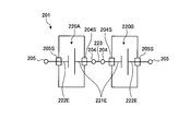
- FIG. 10 is an electric circuit diagram of a power storage device in which single power storage cells are connected in series.
- the power storage cells 220A and 220B included in the power storage device 201 illustrated in FIG. 10 each have an inter-terminal voltage E, and the inter-terminal voltage of the power storage device 201 (the voltage between the two terminals 205) is 2 ⁇ E.
- the first lead portion 221E and the second lead portion 222E are drawn from the housing 203 and are electrically connected to terminals 204 and 205 as external connection terminals, respectively.
- the storage cells 220A and 220B have two insulators 204S and 205S, respectively, in order to ensure insulation between the housing 203 and the first drawer 221E and the second drawer 222E. Therefore, the power storage device 201 having the two power storage cells 220A and 220B has a total of four insulators. In addition, the power storage device 201 electrically connects the terminal 204 of the power storage cell 220A and the terminal 204 of the power storage cell 220B using the power storage cell connection bar 223 in order to connect the two power storage cells 220A and 220B in series. .
- FIG. 11 is an electric circuit diagram of the power storage device according to the first embodiment.
- the first power storage cell 2 ⁇ / b> A and the second power storage cell 2 ⁇ / b> B included in the power storage device 1 illustrated in FIG. 11 each have an inter-terminal voltage E, and the inter-terminal voltage of the power storage device 1 (the first terminal 4 and the second terminal 5 The voltage between) is 2 ⁇ E.
- the power storage device 1 connects the first power storage cell 2A and the second power storage cell 2B in series via the first lead portion 21E and the housing 3, and via the second lead portion 22E. Connect to external connection terminals (first terminal 4 and second terminal 5).
- the potential of the housing 3 is half (E) of the voltage between the terminals of the power storage device 1.
- the potential of the housing 3 becomes an intermediate potential of the power storage device 1.
- the power storage device 1 has a structure in which a current flows through the housing 3. With such a structure, the power storage device 1 has two power storage cells, but only two external connection terminals, the first terminal 4 and the second terminal 5, are required. And the insulator for ensuring the insulation with the 1st terminal 4 and the 2nd terminal 5 as a housing
- casing 3 and an external connection terminal may be two, the 1st seal member 4S and the 2nd seal member 5S.
- the power storage device 201 in FIG. 10 requires the storage cell connection bar 223, but the power storage device 1 electrically connects the first power storage cell 2 ⁇ / b> A and the second power storage cell 2 ⁇ / b> B via the housing 3. In order to connect, the storage cell connection bar 223 is unnecessary. For this reason, the power storage device 1 can reduce the number of parts.
- the power storage device 1 the first polar body 21 of the first power storage cell 2A and the first polar body 21 of the second power storage cell 2B are connected to the housing 3 without an external connection terminal. For this reason, the power storage device 1 can reduce the number of external connection terminals when two power storage cells are connected in series. As a result, the power storage device 1 has a simple structure, so that the manufacturing cost is reduced and the reliability is improved. Moreover, since the housing
- the first power storage cell 2 ⁇ / b> A and the second power storage cell 2 ⁇ / b> B generate heat, but the first electrode body 21 is connected to the housing 3 having good thermal conductivity. For this reason, the heat generated in the first power storage cell 2 ⁇ / b> A and the second power storage cell 2 ⁇ / b> B is transmitted from the first polar body 21 to the housing 3 and is radiated from the surface of the housing 3. For this reason, the electrical storage apparatus 1 has the advantage that heat dissipation performance is high. Note that unevenness or fins may be provided on the surface of the housing 3. In this case, since the surface area of the housing 3 is increased, the heat dissipation performance of the power storage device 1 is further improved.
- the power storage device 1 stores an electrolyte (electrolytic solution) in the first storage chamber 6 and the second storage chamber 7 in addition to the first storage cell 2A and the second storage cell 2B. For this reason, the power storage device 1 provides the first seal member 4S and the second seal member 5S between the lid 3T of the housing 3 and the first terminal 4 and the second terminal 5 to seal the inside of the housing 3. is doing. Since the first terminal 4 and the second terminal 5 and the housing 3 are all conductors, they need to be insulated. It is difficult to achieve both the sealing of the housing 3 and the insulation between the housing 3 and the first terminal 4 and the second terminal 5 and to improve the reliability.
- the power storage device 201 (see FIG.
- the power storage device 1 has two power storage cells 220A and 220B connected in series, and a total of four insulators are used for the sealing and the insulation.
- the power storage device 1 has two first power storage cells 2A and a second power storage cell 2B connected in series.
- the first seal member 4S and the second seal are used for the sealing and the insulation.
- Two of the members 5S may be used.
- ⁇ Method for manufacturing power storage device> 12 to 16 are diagrams illustrating a method for manufacturing the power storage device according to the first embodiment.
- a structure 3 ⁇ / b> D, a first power storage cell 2 ⁇ / b> A, and a second power storage cell 2 ⁇ / b> B in which the side circumferential member 3 ⁇ / b> S and the bottom 3 ⁇ / b> B are integrally formed are prepared.
- the structure 3D is a part of the housing 3 shown in FIG.
- the first connection conductor 25 is electrically connected to the first lead portion 21E of the first power storage cell 2A and the second power storage cell 2B, and the second connection conductor 26 is electrically connected to the second lead portion 22E.
- the first lead portion 21E and the first connection conductor 25 are electrically connected by a joining means such as welding or ultrasonic joining.
- the second lead portion 22E and the second connection conductor 26 are similarly connected.
- the first storage cell 2A is stored in the first storage chamber 6 of the structure 3D
- the second storage cell 2B is stored in the second storage chamber 7.
- the first lead portion 21E and the second lead portion 22E included in the first power storage cell 2A and the second power storage cell 2B are placed on the opening side of the first storage chamber 6 and the second storage portion 7 included in the structure 3D.
- the first connection conductor 25 of the first storage cell 2A is electrically connected to the first protrusion 10 provided on the lid 3T, and the first connection of the second storage cell 2B.
- the conductor 25 is electrically connected to the second protrusion 11 provided on the lid 3T. Further, as shown in FIG.
- the second connection conductor 26 of the first storage cell 2A is electrically connected to the first conductor connection portion 4C of the first terminal 4 provided on the lid 3T, so that the second storage cell
- the 2B second connection conductor 26 is electrically connected to the second conductor connection portion 5C of the second terminal 5 provided on the lid 3T.
- a joining means such as welding or ultrasonic joining is used.
- an electrolyte (electrolytic solution) ES is injected into the first storage chamber 6 and the second storage chamber 7. Then, as shown in FIG. 15, the lid 3T is moved closer to the side circumferential member 3S (the direction indicated by the arrow C in FIG. 15), and the lid 3T is placed on the end of the side circumferential member 3S on the opening side. . Next, as shown in FIG. 16, the boundary portion between the lid 3T and the side circumferential member 3S is joined using a joining means such as welding or ultrasonic joining, and both are fixed. In this way, the power storage device 1 is completed.
- a joining means such as welding or ultrasonic joining
- the electrolyte ES may be injected into the first storage chamber 6 and the second storage chamber 7 from the gas vents 9A and 9B after the lid 3T is joined to the side circumferential member 3S. Since this power storage device manufacturing method uses the structure 3D manufactured by impact molding, the step of joining the bottom 3B and the side peripheral member 3S can be omitted, and the number of components can be reduced. Next, connecting a plurality of power storage devices 1 in series will be described.
- 17 and 18 are diagrams illustrating an example in which a plurality of power storage devices according to Embodiment 1 are connected in series.
- 19 and 20-1 are diagrams showing an example in which a plurality of single storage cells shown in FIG. 10 are connected in series.
- FIG. 20-2 is a diagram illustrating a housing of the power storage device according to the present embodiment.
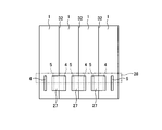
- FIG. 20C is a diagram illustrating an example in which two single storage cells illustrated in FIG. 10 are connected in series. In the example shown in FIGS. 17 and 18, four power storage devices 1 are connected in series.
- one power storage device 1 has two power storage cells, that is, the first power storage cell 2A and the second power storage cell 2B.
- the voltage between the terminals of the first power storage cell 2A and the voltage between the terminals of the second power storage cell 2B is E
- the voltage between the first terminal 4 and the second terminal 5 of one power storage device 1 is 2 ⁇ E. It becomes.
- the voltage between the terminals is 8 ⁇ E.
- an insulator 32 is interposed between adjacent power storage devices 1. This is because the housing 3 of the power storage device 1 is at an intermediate potential of the power storage device 1, so that a short circuit between adjacent power storage devices 1 is avoided.
- the plurality of power storage devices When a plurality (four in this embodiment) of the power storage devices 1 are connected in series, the plurality of power storage devices in a direction parallel to the direction in which the first terminal 4 and the second terminal 5 of the power storage device 1 are arranged. 1 is arranged. That is, the first terminal 4 and the second terminal 5 are arranged in a direction parallel to the direction in which the plurality of power storage devices 1 are arranged. Since the housing 3 of the power storage device 1 is a conductor, an insulator is interposed between the adjacent power storage devices 1. Since the first terminal 4 and the second terminal 5 are opposed to each other, when the plurality of power storage devices 1 are arranged, the plurality of first terminals 4 and the second terminals 5 are arranged in a straight line.
- connection bar 27 is a conductor having a substantially rectangular shape (including a square) in plan view, and for example, aluminum alloy or copper can be used.
- the connection bar 27 and the adjacent first terminal 4 and second terminal 5 are connected by a joining means such as welding.
- the connection bar 27 is connected to the ends of the adjacent first terminal 4 and second terminal 5. Since the first terminal 4 and the second terminal 5 are arranged in a direction parallel to the direction in which the plurality of power storage devices 1 are arranged, the connection bars 27 are arranged in a straight line.
- connection bars 27 four power storage devices 1 are electrically connected by three connection bars 27, and a total of eight power storage cells are connected in series.
- the voltage between the terminals that is, the first terminal 4 that is not connected to the connection bar 27 and the second terminal 5 that is also not connected to the connection bar 27. Is 8 ⁇ E.
- the balance circuit board 28 on which the balance circuit is mounted is disposed in the vicinity of the connection bar.
- the balance circuit board 28 is disposed at a position facing each connection bar 27. More specifically, the balance circuit board 28 is mounted on the connection bar 27, and both are fastened by the screw 29B.
- the balance circuit is electrically connected to the first terminal 4, the second terminal 5, and the housing 3 of the power storage device 1. For this reason, when four power storage devices 1 are connected in series, the balance circuit board 8 is electrically connected to the four power storage devices 1 in a total of nine locations. In the example shown in FIG.
- the balance circuit board 8 is electrically connected to the first terminal 4, the second terminal 5, the four housings 3, and the four connection bars 27.
- the first terminal 4, the second terminal 5, and the four housings 3 are provided with connection pins 29 T welded to the housing 3, the first terminal 4, and the second terminal 5, respectively.
- the four connection bars 27 are electrically connected to the balance circuit board 28 via screws 29B.
- FIG. 19 shows an example in which a plurality of single power storage devices 201 having an inter-terminal voltage E are connected in series.
- the power storage device 201 having an inter-terminal voltage of E are connected in series.
- the eight power storage devices 201 are connected in series by electrically connecting the terminals 204 of the eight power storage devices 201 and the terminals 205 with the connection bar 227. When eight power storage devices 201 are connected in series, seven connection bars 227 are required.
- the power storage device 201 is rectangular when viewed from the terminal 204 and the terminal 205, that is, rectangular in plan view, but the terminal 204 and the terminal 205 are arranged in the longitudinal direction of the power storage device 201 in plan view. . Therefore, the connection bars 227 are alternately arranged on both sides in the longitudinal direction of the power storage device 201 in a plan view, and electrically connect the terminals 204 and the terminals 205 of the adjacent power storage devices 201. With such a structure, when a plurality of power storage devices 201 are connected in series, one balance circuit board 228 is disposed so as to include all the terminals 204 and the terminals 205.
- the area of the balance circuit board 228 becomes large. As shown in FIGS. 17 and 18, if a plurality of power storage devices 1 are connected in series, the area of the balance circuit board 28 can be reduced as compared to a case where a plurality of single power storage devices 201 are connected in series.
- the power storage device 201a shown in FIG. 20-1 has a rectangular shape in plan view, and the terminals 204 and 205 are arranged in the short direction in plan view.
- the terminal 204 and the terminal 205 are arranged in a straight line in the direction in which the plurality of power storage devices 201a are arranged.
- the balance circuit board 228 may be arranged in the direction in which the first terminals 4 and the second terminals 5 are arranged, so only one is required.
- each power storage device 201a has the first terminal 4 and the second terminal 5, when connecting the eight power storage devices 201a in series, seven connection bars 227 are required. Become.
- the power storage device 1 When a plurality of power storage devices 1 or power storage devices 201 and 201a are connected in series to form a single assembly, the power storage device 1 is connected to a single power storage device 201 and 201a as long as the voltage across the terminals of the assembly is the same. In comparison, the number of connection bars 27 can be reduced to half or less. For this reason, the power storage device 1 can simplify the connection work when a plurality of power storage devices 1 are connected in series to manufacture one assembly. In addition, when a plurality of power storage devices 1 are connected in series, if the number of connection locations is reduced, the possibility of occurrence of a connection failure is reduced accordingly, so that the reliability is improved.
- connection bar 27 Since the number can be reduced, the number of connection bars 27 can be reduced, and the number of connection points between the first terminal 4 and the second terminal 5 and the connection bar 27 can be reduced. As a result, the reliability of the assembly is improved. To do. Furthermore, the connection bar 27 is disposed on the first terminal 4 and second terminal 5 side of the power storage device 1, that is, above the power storage device 1 (on the opposite side in the vertical direction). For this reason, the connection bar 27 increases the center of gravity of the power storage device 1. Since the power storage device 1 can reduce the number of connection bars 27 by about half compared to the case where the single power storage devices 201 and 201a are connected, the power storage device 1 also contributes to a lower center of gravity. In particular, when a plurality of power storage devices 1 are connected in series, the effect of lowering the center of gravity is great.
- connection portion between the connection bar 27 and the first terminal 4 and the second terminal 5, but heat is generated due to the electric resistance of the connection portion, resulting in loss of electric energy. For this reason, since the one where the number of the said connection places is smaller can utilize an electrical energy effectively, it is preferable.
- the power storage device 1 by reducing the number of connection bars 27, the number of connection points is reduced, so that loss of electrical energy can be reduced. Further, the assembly of the power storage device 1 also reduces the amount of heat generated due to the connection location.
- the balance circuit of the power storage device 1 Since the balance circuit of the power storage device 1 is electrically connected to the first terminal 4 and the second terminal 5, when four power storage devices 1 are connected in series, the balance circuit has a total of eight terminals ( The first terminal 4 and the second terminal 5) are electrically connected. On the other hand, when eight power storage devices 201 and 201a are connected in series, the balance circuit is electrically connected to a total of 16 terminals (terminal 204 and terminal 205). As described above, since the power storage device 1 can reduce the number of terminals connected to the balance circuit, there are advantages in that the structure is simplified and the cost is reduced.
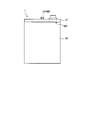
- the housing 3 of the power storage device 1 When manufacturing the housing 3 of the power storage device 1 by impact molding, it is necessary to chamfer the corner 3R with a curved surface as shown in FIG. 20-2 in order to ensure the fluidity of the material.
- the adjacent energy storage cells 201 are adjacent to each other due to the chamfering of the curved surface provided at the corner 203R of the housing 203 included in one energy storage cell 201.
- the contact area becomes smaller.
- the power storage device 1 stores the first power storage cell 2 ⁇ / b> A and the second power storage cell 2 ⁇ / b> B in one housing 3.
- the power storage device 1 having two power storage cells that is, the first power storage cell 2A and the second power storage cell 2B, has higher heat dissipation than the case where two single power storage cells 201 are combined. .
- FIG. 21 and FIG. 22 are diagrams showing an example of the mounting structure of the power storage device according to this embodiment.
- the power storage device 1 has the housing 3 attached to the surface of the side circumferential member 3 ⁇ / b> S and the bottom 3 ⁇ / b> B side as the end side member from which the first terminal 4 and the second terminal 5 are not taken out.
- the bracket 30 is provided as a mounting portion for mounting to the power storage device mounting body 34.
- the bracket 30 is made of resin.
- the bracket 30 is provided in two places of the side periphery member 3S of the two electrical storage apparatuses 1, and has couple
- the bracket 30 can be provided on the side peripheral member 3S of the housing 3 by insert molding.
- An insulator 32 is interposed between the two power storage devices 1 to avoid conduction between the conductor casings 3.
- the insulator 32 may be a resin like the bracket 30.
- Each bracket 30 has a mounting hole 31. As shown in FIG. 22, the bolt 33 is passed through the attachment hole 31, and the bolt 33 is screwed into the bolt hole 35 provided in the power storage device attachment body 34. At this time, an insulating sheet 39 as an insulator is interposed between the power storage device 1 and the power storage device mounting body 34.
- the power storage device mounting body 34 is made of a good heat conductor such as metal, and in this embodiment, an aluminum alloy is used. For this reason, it is for ensuring the electrical insulation between the some electrical storage apparatuses 1 attached to the electrical storage apparatus attachment body 34.
- FIG. As the insulating sheet 39 it is preferable to use a sheet having good thermal conductivity. In this way, the heat generated by the first power storage cell 2A and the second power storage cell 2B housed in the power storage device 1 can be efficiently transmitted to the power storage device attachment 34.
- An insulator is also provided between the bolt 33 and the power storage device mounting body 34.
- the power storage device attachment 34 has a cooling medium passage 36.
- the heat of the power storage device 1 attached to the power storage device attachment 34 is cooled by a cooling medium (for example, water) flowing through the cooling medium passage 36.
- a cooling medium for example, water
- Such a cooling structure is preferable when the power storage device 1 is disposed in a sealed space and cooling by an air flow cannot be expected, for example, when it is mounted on a hybrid construction machine.
- the first polar body 21 of the first power storage cell 2A and the second power storage cell 2B is electrically and thermally connected to the housing 3.
- the heat of the 1st electrical storage cell 2A and the 2nd electrical storage cell 2B is efficiently transmitted to the housing
- FIG. As a result, the heat generated inside the power storage device 1 is efficiently transmitted to the cooling medium, and the cooling efficiency of the power storage device 1 is improved.
- the power storage device 1 is preferable when it is disposed in a sealed space.
- Bracket 30 is attached to the first terminal 4 and the second terminal 5 side of the power storage device 1.
- Another bracket 30 is attached to a side peripheral member 3S of the power storage device 1 different from the power storage device 1 having the bracket 30 on the first terminal 4 and second terminal 5 sides. The location is opposite to the first terminal 4 and the second terminal 5.
- the thickness of the bottom portion 3B may not be increased by using the bracket 30. For this reason, heat is easily transferred from the bottom 3B to the power storage device attachment 34, and the cooling performance of the power storage device 1 is improved. Furthermore, since the thickness of the bottom 3B can be reduced by using the bracket 30, the height of the power storage device 1 (the dimension in the direction from the bottom 3B to the lid 3T) can be reduced. As a result, since the center of gravity of power storage device 1 can be lowered, the stability of power storage device 1 is improved. Since the total mass of the plurality of power storage devices 1 increases as the number of power storage devices 1 increases, the effect of lowering the center of gravity of the power storage devices 1 becomes more prominent as the number of power storage devices 1 connected in series increases. .
- the power storage device 1 has two power storage cells, that is, a first power storage cell 2A and a second power storage cell 2B connected in series. For this reason, the housing
- the power storage device 1 can halve the number of brackets 30 as compared to the case where the brackets 30 are attached to individual power storage cells. For this reason, when the same number of power storage cells are connected in series, the power storage device 1 can halve the effort required to attach the bracket 30 and reduce the manufacturing cost compared to the case where a single power storage cell is connected in series. .
- the power storage device 1 is suitable for a structure in which the bracket 30 is attached to the side peripheral member 3S of the housing 3.
- FIG. 23 is a diagram illustrating another example of the mounting structure of the power storage device according to the present embodiment.
- a bolt 38 is screwed into a bolt hole 3BH provided in the bottom 3B of the housing 3 of the power storage device 1 from a through hole 37 provided in the power storage device mounting body 34, and the power storage device 1 is connected to the power storage device mounting body. 34 is fixed.
- the insulating sheet 39 and the insulating washer 39W are interposed between the bottom 3B and the power storage device attachment body 34.
- the bolt 38 passes through the insulating washer 39W and is screwed into the bolt hole 3BH. Since this mounting structure does not require the bracket 30, the area occupied by the power storage device 1 can be reduced.
- ⁇ Power storage device assembly> 24 to 26 are plan views showing a power storage device assembly having a plurality of power storage devices according to the present embodiment.
- a power storage device assembly 110 illustrated in FIG. 24 includes a plurality of power storage devices 1 connected in series.
- the power storage device assembly 110 has a plurality of two power storage devices 1 combined by the two brackets 30 shown in FIGS. 21 and 22, and these are connected in series.
- the power storage device assembly 110 has a total of eight power storage devices 1.
- the plurality of power storage devices 1 are arranged inside the assembly housing 111 and are attached to the power storage device mounting body 34 described above and sealed from the outside.
- the power storage device assembly 110 includes a balance circuit board 28 having a balance circuit for adjusting the balance of electrical characteristics among the plurality of power storage devices 1.
- the power storage device assembly 110A shown in FIG. 25 has a plurality of (three in this example) power storage devices 1 as one unit so that the first terminal 4 and the second terminal 5 of the one unit of power storage device 1 face each other. It is arranged. In this way, since the first terminals 4 and the second terminals 5 of the plurality of power storage devices 1 are close to each other, there is an advantage that only one balance circuit board 28 is required.
- the power storage device assembly 110B illustrated in FIG. 26 includes a plurality of one unit of power storage device assembly 110A with the power storage device assembly 110A illustrated in FIG. 25 as one unit. As described above, when a large number of power storage devices 1 are connected in series, maintenance and inspection are facilitated by dividing the plurality of power storage devices 1 into a plurality of units.
- FIG. 27 is a diagram illustrating the power storage device according to the second embodiment.
- FIG. 28 is a side view illustrating the power storage device according to the second embodiment.
- FIG. 29 is a plan view illustrating the power storage device according to the second embodiment.
- FIG. 30 is a perspective view illustrating a first power storage cell and a second power storage cell included in the power storage device according to the second embodiment.
- the power storage device 1a of the present embodiment is the same as the power storage device 1 of the first embodiment, but the side circumferential member 3Sa and the bottom 3Ba of the housing 3a made of different members are integrated by a joining means such as welding. Is different. Accordingly, the structures of the first power storage cell 2Aa and the second power storage cell 2Ba are also different. Other configurations of the power storage device 1a are the same as those of the power storage device 1 according to the first embodiment.
- the housing 3a of the power storage device 1a has a lid 3Ta, a side circumferential member 3Sa, and a bottom 3Ba.
- the side circumferential member 3Sa and the bottom 3Ba are manufactured as separate members and connected by welding or the like.
- the housing 3a is made of the same material as the housing 3 of the first embodiment.
- the side circumferential member 3Sa is a cylindrical member through which the first storage chamber 6 and the second storage chamber 7 penetrate from one end 3St1 to the other end 3St2.
- the side circumferential member 3Sa has a partition member 8a inside.
- the side circumferential member 3Sa and the partition member 8a are integrally formed by, for example, extrusion molding.
- the lid 3Ta is in contact with one end 3St1 of the side peripheral member 3Sa and one end 8at1 of the partition member 8a, and the bottom 3Ba is the other end 3St2 of the side peripheral member 3Sa and the other end of the partition member 8a. Touch 8at2.
- the first storage cell 2Aa is stored in the first storage chamber 6, and the second storage cell 2Ba is stored in the second storage chamber 7. As shown in FIG. 30, the first power storage cell 2Aa and the second power storage cell 2Ba have the same structure, and therefore only the first power storage cell 2Aa will be described as necessary.
- the first storage cell 2Aa has a first polar body 21a and a second polar body 22a.
- the first polar body 21a has a first current collector 21C and a first lead part 21E
- the second polar body 22a has a first current collector 22C and a second current collector 22C.
- a separator 23 is sandwiched between the first current collector 21C and the second current collector 22C.
- the first polarizable electrode 24A shown in FIGS. 8 and 9 is provided on the surface of the first current collector 21C of the first polar body 21a
- the surface of the second current collector 22C of the second polar body 22 is The point that the second polarizable electrode 24B shown in FIGS. 8 and 9 is provided and the point that the first polarizable electrode 24A and the second polarizable electrode 24B face the separator 23 are the same as in the first embodiment.
- the first drawing portion 21E and the second drawing portion 22E are drawn in opposite directions from the first current collecting portion 21C and the second current collecting portion 22C, respectively.
- the first lead portion 21E of the first power storage cell 2Aa and the first lead portion 21E of the second power storage cell 2Ba are electrically connected to the bottom 3Ba.
- the second lead portion 22E of the first power storage cell 2Aa and the second lead portion 22E of the second power storage cell 2Ba are electrically connected to the first terminal 4 and the second terminal 5 through the second connection conductor 26, respectively. Connected to.
- the direction in which the first terminal 4 and the second terminal 5 are pulled out from the lid 3Ta of the housing 3 is such that the first polar body 21a of the first power storage cell 2Aa and the first polar body 21a of the second power storage cell 2Ba are connected.
- the lead portion for electrical connection that is, the first lead portion 21E is opposite to the direction extending from the first polar body 21a of the first storage cell 2Aa and the first polar body 21a of the second storage cell 2Ba. Become a direction.
- the 1st drawer part 21E is arranged on the opposite side to the 1st terminal 4 and the 2nd terminal 5, the area and place where the 1st drawer part 21E is connected with bottom 3Ba is It is not affected by the first terminal 4 and the second terminal 5.
- the area where the first lead portion 21E and the bottom portion 3Ba are connected can be increased, and heat can be more efficiently transferred from the first polar body 21a to the bottom portion 3Ba.
- drawing-out part 21E improves.
- the electrical storage apparatus 1a can transmit the heat
- the electrical storage apparatus 1a can transmit the heat
- 31 to 34 are diagrams illustrating a method for manufacturing the power storage device according to the second embodiment.
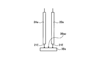
- the first lead portion 21E of the first polar body 21a and the first lead portion 21E of the second polar body 22a are connected to the surface of the bottom 3Ba. Connect to 3Bap. These are electrically and thermally connected by welding, for example.
- the first storage cell 2Aa and the second storage cell 2Ba are connected to the first storage chamber from the other end 3St2 of the side circumferential member 3Sa and the other end 8at2 side of the partition member 8a. 6 and the second storage chamber 7.
- the connecting portion MP between the side circumferential member 3Sa and the bottom 3Ba is welded or the like. Be joined.
- the second connection conductor 26 to which the second lead portion 22E of the first power storage cell 2Aa is connected and the second connection conductor to which the second lead portion 22E of the second power storage cell 2Ba is connected. 26 are respectively connected to the first conductor connecting portion 4C of the first terminal 4 and the second conductor connecting portion 5C of the second terminal 5 by welding or the like. Thereafter, an electrolyte (electrolytic solution) ES is injected into the first storage chamber 6 and the second storage chamber 7.
- the connecting portion between the side circumferential member 3Sa and the lid 3Ta is joined by welding or the like.
- the power storage device 1a is completed as shown in FIG.
- the side circumferential member 3Sa can be manufactured relatively easily by extrusion molding.
- FIG. 35 is a diagram illustrating the power storage device according to the third embodiment.
- 36 is a cross-sectional view taken along the line EE of FIG.
- the power storage device 1b electrically connects the first lead portion 21E of the first power storage cell 2Aa and the first lead portion 21E of the second power storage cell 2Ba to the partition member 8b, and the housing 3b and the partition member 8b One power storage cell 2Aa and the second power storage cell 2Ba are covered.
- Other configurations are the same as those of the power storage device 1 according to the first embodiment.
- the partition member 8b is a single plate-like member.
- the partition member 8b has a rectangular shape (including a square) in a plan view (a shape when viewed from a direction orthogonal to the plate surface), but is not limited thereto.
- the partition member 8b is manufactured by press-molding a sheet metal, for example.
- the partition member 8b is a conductor, and in this embodiment is an aluminum alloy.
- the material of the partition member 8b is not limited to this.
- the first terminal 4b and the second terminal 5b are disposed on one end 8bt1 side, and the first lead portion 21E of the first storage cell 2Aa and the second storage cell 2Ba are disposed on the other end 8bt2 side. Are electrically connected to the second lead portion 22E.
- the insulator 13A and the insulator 13B are provided between the partition member 8b and the first energy storage cell 2Aa and the second energy storage cell 2Ba.
- the insulators 13A and 13B ensure electrical insulation between the first power storage cell 2Aa and the second power storage cell 2Ba and the partition member 8b.
- the housing 3b is provided on the first power storage cell 2Aa side and the second power storage cell 2Ba side with the partition member 8b as the center.
- the housing 3b is a sheet-like member having a rectangular shape (including a square) in plan view.
- the housing 3b has a structure in which an outer layer 12A such as a metal foil and an insulating layer 12B such as a resin are laminated, but is not limited thereto.
- the two housings 3b are sealed at the outer periphery of the partition member 8b with the insulating layer 12B facing the first power storage cell 2Aa and the second power storage cell 2Ba and wrapped with the partition member 8b.
- the sealing portion 15 is formed at this portion.
- a joining means such as ultrasonic fusion can be used.
- a part of the surface of the first terminal 4b and a part of the surface of the second terminal 5b are covered with the seal member 4Sb and the seal member 5Sb, respectively.
- the seal members 4Sb and 5Sb are sandwiched between the housing 3b and the partition member 8b.
- the seal members 4Sb and 5Sb insulate the first terminal 4b and the second terminal 5b from the partition member 8b, and two spaces surrounded by the housing 3b and the partition member 8b, that is, the first storage chamber 6b and the first member. 2
- the storage chamber 7 is sealed.
- the first storage cell 6A is stored in the first storage chamber 6b
- the second storage cell 2Ba is stored in the second storage chamber 7.
- FIG. 37 is a diagram illustrating the method for manufacturing the power storage device according to the third embodiment.
- the first lead portion 21E of the first power storage cell 2Aa and the first lead portion 21E of the second power storage cell 2Ba are partitioned.
- the other end 8bt2 side of the member 8b is joined by welding or the like.
- the second lead portion 22E of the first power storage cell 2Aa and the second lead portion 22E of the second power storage cell 2Ba are joined to the first terminal 4b and the second terminal 5b, respectively, by welding or the like.
- the first storage cell 2Aa is covered with one housing 3b
- the second storage cell 2Ba is covered with another housing 3b.
- a part of the first terminal 4b and the second terminal 5b, more specifically, the first storage cell 2Aa and the second storage cell 2Ba side of the seal members 4Sb and 5Sb are also covered with the respective housings 3. Is called.
- casing 3b is joined by the outer peripheral part of the partition member 8b.
- electrolyte (electrolyte solution) ES is inject
- a hybrid construction machine will be described as an example of a machine having a power storage device assembly 110 having a plurality of power storage devices 1 according to the above-described embodiments.
- a hybrid hydraulic excavator is taken as an example, but the application target of the power storage device 1 and the power storage device assembly 110 is not limited to this.
- FIG. 38 is a side view showing the hybrid excavator.
- FIG. 39 is a view taken along the line FF of FIG.
- the hybrid excavator 100 drives a generator motor by an internal combustion engine to generate electric power, and the electric motor is driven by the electric power to turn the upper swing body, or the auxiliary machinery of the hybrid excavator 100 is driven. This is a so-called hybrid construction machine.
- the hybrid excavator 100 includes a lower traveling body 102 having a pair of left and right crawler belts 102C, an upper swing body 103, a boom 104a, an arm 104b and a bucket 104c, and a work machine 104 attached to the upper swing body 103, A swing circle 105 that connects the traveling body 102 and the upper swing body 103 is included.
- the pair of left and right crawler belts 102C are driven by a right traveling hydraulic motor and a left traveling hydraulic motor to cause the hybrid excavator 100 to travel.
- the right traveling hydraulic motor and the left traveling hydraulic motor are driven by being supplied with hydraulic oil fed from the hydraulic pump 107 shown in FIG.
- the upper turning body 103 is turned by an electric motor 105M (see FIG. 39) that functions as a turning motor.
- An outer race 105O of a swing circle 105 is fixed to the upper swing body 103, and an inner race 105I of the swing circle 105 is fixed to the lower traveling body 102.
- the swing circle 105 connects the upper swing body 103 and the lower traveling body 102.
- the input / output shaft of the electric motor 105M is connected to the swing pinion 105P through a swing machinery having a speed reduction mechanism.
- the swing pinion 105P meshes with internal teeth attached to the inner race 105I of the swing circle 105.
- the driving force of the electric motor 105M is transmitted to the swing pinion 105P via the swing machinery, and turns the upper swing body 103.
- the electric motor 105M is installed vertically so that the input / output shaft of the electric motor 105M is directed in the direction in which gravity acts when the hybrid excavator 100 is installed on a horizontal plane.
- the boom 104a, the arm 104b, and the bucket 104c are driven by hydraulic cylinders for the boom 104a, the arm 104b, and the bucket 104c, respectively, via the control valve by hydraulic oil fed from the hydraulic pump 107 shown in FIG. Perform work such as excavation.
- the upper turning body 103 is a structure having a substantially rectangular shape in plan view.
- the cockpit 103a of the upper swing body 103 is disposed on the left side in front of the upper swing body 103 when the direction in which the operator's line of sight is mainly directed during the operation of the hybrid excavator 100 is assumed to be forward.
- the counterweight 103 b is disposed behind the upper swing body 103.
- the upper swing body 103 includes an internal combustion engine 106 as a power generation source of the hybrid excavator 100, a generator motor 109 according to the present embodiment, a hydraulic pump 107, an inverter 108, And a power storage device assembly 110 in which a plurality of the power storage devices 1 described above are connected in series.
- the internal combustion engine 106 is, for example, a diesel engine, but the type of the internal combustion engine 106 is not limited.
- the internal combustion engine 106, the generator motor 109, the hydraulic pump 107, the inverter 108, and the power storage device assembly 110 are disposed in front of the counterweight 103b, that is, on the cockpit 103a side.
- a generator motor 109 is disposed between the internal combustion engine 106 and the hydraulic pump 107.
- the output shaft 106S of the internal combustion engine 106 is connected to the input / output shaft of the generator motor 109, and the input / output shaft of the generator motor 109 is connected to the input shaft 107S of the hydraulic pump 107.
- the internal combustion engine 106 drives the generator motor 109 to generate electric power and drives the hydraulic pump 107. That is, the hydraulic pump 107 is driven via the generator motor 109.
- the generator motor 109 may be indirectly connected to the output shaft of the engine via a PTO (Power Take Off).
- the high voltage wiring CAa is electrically connected to the input / output terminal of the inverter 108 and the power input / output terminal of the generator motor 109.
- a high voltage wiring CAb is electrically connected to the output terminal of the inverter 108 and the input terminal of the electric motor 105M.
- the inverter 108 stores the electric power generated by the generator motor 109 in the power storage device assembly 110, or supplies the electric power to the electric motor 105M to drive it. Further, the inverter 108 stores, in the power storage device assembly 110, electric power obtained by the electric motor 105M converting the kinetic energy of the upper swing body 103 into electrical energy when the swing brake is operated on the upper swing body 103. .
- the electric power stored in the power storage device assembly 110 is supplied to the electric motor 105M by the inverter 108 when the upper swing body 103 turns next time.
- the generator motor 109 can operate as a motor by receiving power supply from the power storage device assembly 110 as needed, and can assist the internal combustion engine 106.
- the above-described power storage device assembly 110 is applied to the hybrid excavator 100 which is a kind of construction machine.
- the application target of the power storage device assembly 110 is not limited to the hybrid excavator 100.
- the power storage device assembly 110 may be applied to other hybrid construction machines such as a wheel loader.
- Construction machines such as the hybrid excavator 100 are normally used on rough terrain, and the working machine 104 and the upper swing body 103 are subjected to rapid acceleration / deceleration or a large load is applied. Thus, construction machines are often used under severe conditions. For this reason, the power storage device assembly 110 mounted on the construction machine is also subjected to rapid acceleration / deceleration, vibration or impact, or a large current is passed to the electric motor 105M in order to accelerate the upper turning zone 103 rapidly. So it is used in harsh conditions.
- the power storage device assembly 110 can reduce the number of connection bars 27 shown in FIGS. 17 and 18 and can also reduce the number of connection points between the second terminals 5 and the connection bars 27.
- the power storage device assembly 110 includes a first seal member 4S and a second seal member 5S (sealing locations) provided between the first terminal 4 and the second terminal 5 (external terminal) and the lid 3T (housing). ) Can be reduced, so that reliability can be improved.
- the power storage device assembly 110 can reduce the number of the connection portions and the sealing portions that are easily affected by vibration or impact, and thus can maintain high reliability.
- the power storage device assembly 110 when used as a power supply source for driving an electric motor or the like, a high voltage is required, and as a result, the number of power storage devices 1 in series increases, so that the connection location and the sealing location are also To increase. Since the power storage device assembly 110 can reduce the number of the connection locations and the sealing locations, the power storage device assembly 110 is suitable for applications in which many power storage devices 1 are connected in series, such as a hybrid construction machine.
- the power storage device assembly 110 houses and seals the plurality of power storage devices 1 inside the assembly housing 111 (see FIG. 24).
- the power storage device 1 included in the power storage device assembly 110 can efficiently transfer the heat generated in the first power storage cell 2A and the second power storage cell 2B to the housing 3 through the connected first electrode body 21. . Therefore, the power storage device assembly 110 efficiently transfers the heat of the first power storage cell 2A and the second power storage cell 2B to the power storage device attachment 34 via the housing 3 even when the power storage device 1 is sealed. Accordingly, it is possible to suppress an excessive temperature rise of the power storage device 1.
- the mounting structure in which the bracket 30 is provided on the side circumferential member 3 ⁇ / b> S of the power storage device 1 and fixed to the mounting target can keep the center of gravity of the power storage device assembly 110 low.
- the power storage device assembly 110 having such an attachment structure is preferable because it can contribute to lowering the center of gravity of the construction machine.
- the power storage device assembly 110 is suitable for a construction machine.
Landscapes
- Chemical & Material Sciences (AREA)
- Chemical Kinetics & Catalysis (AREA)
- Electrochemistry (AREA)
- General Chemical & Material Sciences (AREA)
- Engineering & Computer Science (AREA)
- Power Engineering (AREA)
- Aviation & Aerospace Engineering (AREA)
- Microelectronics & Electronic Packaging (AREA)
- Connection Of Batteries Or Terminals (AREA)
- Electric Double-Layer Capacitors Or The Like (AREA)
- Battery Mounting, Suspending (AREA)
Abstract
Le dispositif d'accumulation de l'invention comprend : une première cellule d'accumulation (2A) et une deuxième cellule d'accumulation (2B) qui sont capables de se charger et de se décharger ; un couvercle (3T) d'un boîtier (3), une première électrode de la première cellule d'accumulation (2A) et une première électrode de la deuxième cellule d'accumulation (2B) étant reliées électriquement au boîtier (3), ledit boîtier (3) comprenant également une première chambre de logement (6) qui loge la première cellule d'accumulation (2A) et une deuxième chambre de logement (7) qui loge la deuxième cellule d'accumulation (2B) ; une première borne (4) qui est reliée électriquement à la deuxième électrode de la première cellule d'accumulation (2A) et qui est extrudée de manière externe par rapport au boîtier (3) ; et une deuxième borne (5) qui est reliée électriquement à la deuxième électrode de la deuxième cellule d'accumulation (2B) et qui est extrudée de manière externe par rapport au boîtier (3).
Applications Claiming Priority (2)
| Application Number | Priority Date | Filing Date | Title |
|---|---|---|---|
| JP2011172390A JP2013038192A (ja) | 2011-08-05 | 2011-08-05 | 蓄電装置及び蓄電装置集合体並びに蓄電装置の製造方法 |
| JP2011-172390 | 2011-08-05 |
Publications (1)
| Publication Number | Publication Date |
|---|---|
| WO2013021925A1 true WO2013021925A1 (fr) | 2013-02-14 |
Family
ID=47668433
Family Applications (1)
| Application Number | Title | Priority Date | Filing Date |
|---|---|---|---|
| PCT/JP2012/069763 Ceased WO2013021925A1 (fr) | 2011-08-05 | 2012-08-02 | Dispositif d'accumulation, agrégat de dispositifs d'accumulation et procédé de fabrication du dispositif d'accumulation |
Country Status (2)
| Country | Link |
|---|---|
| JP (1) | JP2013038192A (fr) |
| WO (1) | WO2013021925A1 (fr) |
Cited By (1)
| Publication number | Priority date | Publication date | Assignee | Title |
|---|---|---|---|---|
| EP3089345B1 (fr) * | 2013-12-26 | 2021-08-18 | Meidensha Corporation | Structure isolante pour dispositif de conversion de puissance |
Families Citing this family (4)
| Publication number | Priority date | Publication date | Assignee | Title |
|---|---|---|---|---|
| US9564275B2 (en) | 2012-03-09 | 2017-02-07 | The Paper Battery Co. | Supercapacitor structures |
| JP6719909B2 (ja) * | 2016-01-13 | 2020-07-08 | 三菱重工サーマルシステムズ株式会社 | 回路部品の耐振固定構造を備えた回路組立体、および車両用電動圧縮機 |
| JP7267129B2 (ja) * | 2019-07-10 | 2023-05-01 | 本田技研工業株式会社 | 蓄電モジュール |
| JP7018992B2 (ja) * | 2020-06-17 | 2022-02-14 | 三菱重工サーマルシステムズ株式会社 | 耐振固定構造を備えた回路部品、基板、回路組立体、および車両用電動圧縮機 |
Citations (5)
| Publication number | Priority date | Publication date | Assignee | Title |
|---|---|---|---|---|
| JPH0350322U (fr) * | 1989-09-21 | 1991-05-16 | ||
| JP2000243370A (ja) * | 1999-02-23 | 2000-09-08 | Toyota Motor Corp | 集合電池およびその製造方法 |
| JP2003338269A (ja) * | 2002-05-21 | 2003-11-28 | Nissan Motor Co Ltd | 二次電池モジュール |
| JP2008262751A (ja) * | 2007-04-10 | 2008-10-30 | Matsushita Electric Ind Co Ltd | 組電池、単電池及び電池パック |
| JP2008270460A (ja) * | 2007-04-19 | 2008-11-06 | Matsushita Electric Ind Co Ltd | 蓄電ユニット |
-
2011
- 2011-08-05 JP JP2011172390A patent/JP2013038192A/ja not_active Withdrawn
-
2012
- 2012-08-02 WO PCT/JP2012/069763 patent/WO2013021925A1/fr not_active Ceased
Patent Citations (5)
| Publication number | Priority date | Publication date | Assignee | Title |
|---|---|---|---|---|
| JPH0350322U (fr) * | 1989-09-21 | 1991-05-16 | ||
| JP2000243370A (ja) * | 1999-02-23 | 2000-09-08 | Toyota Motor Corp | 集合電池およびその製造方法 |
| JP2003338269A (ja) * | 2002-05-21 | 2003-11-28 | Nissan Motor Co Ltd | 二次電池モジュール |
| JP2008262751A (ja) * | 2007-04-10 | 2008-10-30 | Matsushita Electric Ind Co Ltd | 組電池、単電池及び電池パック |
| JP2008270460A (ja) * | 2007-04-19 | 2008-11-06 | Matsushita Electric Ind Co Ltd | 蓄電ユニット |
Cited By (1)
| Publication number | Priority date | Publication date | Assignee | Title |
|---|---|---|---|---|
| EP3089345B1 (fr) * | 2013-12-26 | 2021-08-18 | Meidensha Corporation | Structure isolante pour dispositif de conversion de puissance |
Also Published As
| Publication number | Publication date |
|---|---|
| JP2013038192A (ja) | 2013-02-21 |
Similar Documents
| Publication | Publication Date | Title |
|---|---|---|
| JP5968211B2 (ja) | 蓄電モジュール、その製造方法、及び作業機械 | |
| JP6095813B2 (ja) | 蓄電装置 | |
| CN104067406B (zh) | 挖土机 | |
| JP5791578B2 (ja) | 蓄電モジュール | |
| JP5318844B2 (ja) | 蓄電モジュール及び作業機械 | |
| US20130045403A1 (en) | Battery module having novel structure | |
| CN106803608A (zh) | 电池模组和新能源汽车 | |
| WO2013021925A1 (fr) | Dispositif d'accumulation, agrégat de dispositifs d'accumulation et procédé de fabrication du dispositif d'accumulation | |
| JP2015153743A (ja) | 蓄電装置及びこれを搭載した作業機械 | |
| JP6988393B2 (ja) | 電池モジュール及び電池パック | |
| CN206340634U (zh) | 电池模组和新能源汽车 | |
| JP6573644B2 (ja) | 蓄電デバイス | |
| CN104737325A (zh) | 蓄电模块以及作业机械 | |
| JP2012004398A (ja) | 蓄電モジュール | |
| JP5709133B2 (ja) | 蓄電モジュール | |
| JP5493265B2 (ja) | 電池、組電池およびそれを搭載した車両 | |
| CN120691038A (zh) | 一种模块化动力电池包 | |
| JP6084513B2 (ja) | 蓄電モジュール用電圧均等化装置、蓄電装置及び作業機械 | |
| JP2006196222A (ja) | 電池セル結合体、組電池構造およびその組み立て方法 | |
| CN113782897B (zh) | 电池包及具有该电池包的车辆 | |
| JP2020053198A (ja) | バッテリモジュール | |
| JP2013102000A (ja) | 蓄電装置及び蓄電装置集合体 | |
| CN115764101A (zh) | 汽车底盘和汽车 |
Legal Events
| Date | Code | Title | Description |
|---|---|---|---|
| 121 | Ep: the epo has been informed by wipo that ep was designated in this application |
Ref document number: 12822686 Country of ref document: EP Kind code of ref document: A1 |
|
| NENP | Non-entry into the national phase |
Ref country code: DE |
|
| 122 | Ep: pct application non-entry in european phase |
Ref document number: 12822686 Country of ref document: EP Kind code of ref document: A1 |