WO2013027298A1 - Procédé d'établissement de communication, système informatique et ordinateur - Google Patents
Procédé d'établissement de communication, système informatique et ordinateur Download PDFInfo
- Publication number
- WO2013027298A1 WO2013027298A1 PCT/JP2011/069222 JP2011069222W WO2013027298A1 WO 2013027298 A1 WO2013027298 A1 WO 2013027298A1 JP 2011069222 W JP2011069222 W JP 2011069222W WO 2013027298 A1 WO2013027298 A1 WO 2013027298A1
- Authority
- WO
- WIPO (PCT)
- Prior art keywords
- cluster
- console
- connection
- communication
- data processing
- Prior art date
- Legal status (The legal status is an assumption and is not a legal conclusion. Google has not performed a legal analysis and makes no representation as to the accuracy of the status listed.)
- Ceased
Links
Images



Classifications
-
- G—PHYSICS
- G06—COMPUTING OR CALCULATING; COUNTING
- G06F—ELECTRIC DIGITAL DATA PROCESSING
- G06F1/00—Details not covered by groups G06F3/00 - G06F13/00 and G06F21/00
- G06F1/26—Power supply means, e.g. regulation thereof
- G06F1/28—Supervision thereof, e.g. detecting power-supply failure by out of limits supervision
-
- G—PHYSICS
- G06—COMPUTING OR CALCULATING; COUNTING
- G06F—ELECTRIC DIGITAL DATA PROCESSING
- G06F13/00—Interconnection of, or transfer of information or other signals between, memories, input/output devices or central processing units
-
- G—PHYSICS
- G06—COMPUTING OR CALCULATING; COUNTING
- G06F—ELECTRIC DIGITAL DATA PROCESSING
- G06F13/00—Interconnection of, or transfer of information or other signals between, memories, input/output devices or central processing units
- G06F13/38—Information transfer, e.g. on bus
- G06F13/382—Information transfer, e.g. on bus using universal interface adapter
- G06F13/385—Information transfer, e.g. on bus using universal interface adapter for adaptation of a particular data processing system to different peripheral devices
-
- H—ELECTRICITY
- H04—ELECTRIC COMMUNICATION TECHNIQUE
- H04L—TRANSMISSION OF DIGITAL INFORMATION, e.g. TELEGRAPHIC COMMUNICATION
- H04L43/00—Arrangements for monitoring or testing data switching networks
- H04L43/10—Active monitoring, e.g. heartbeat, ping or trace-route
-
- H—ELECTRICITY
- H04—ELECTRIC COMMUNICATION TECHNIQUE
- H04L—TRANSMISSION OF DIGITAL INFORMATION, e.g. TELEGRAPHIC COMMUNICATION
- H04L65/00—Network arrangements, protocols or services for supporting real-time applications in data packet communication
- H04L65/1066—Session management
- H04L65/1069—Session establishment or de-establishment
-
- H—ELECTRICITY
- H04—ELECTRIC COMMUNICATION TECHNIQUE
- H04L—TRANSMISSION OF DIGITAL INFORMATION, e.g. TELEGRAPHIC COMMUNICATION
- H04L69/00—Network arrangements, protocols or services independent of the application payload and not provided for in the other groups of this subclass
- H04L69/40—Network arrangements, protocols or services independent of the application payload and not provided for in the other groups of this subclass for recovering from a failure of a protocol instance or entity, e.g. service redundancy protocols, protocol state redundancy or protocol service redirection
Definitions
- the present invention relates to a technique for establishing communication between a plurality of computers and a data processing device via a network.
- console data processing device
- console When a console is connected to a network where multiple computers are connected, the console can communicate with all computers. Therefore, the operator does not have to move according to the computer to be managed.
- a protocol in which the console can communicate in parallel (simultaneously) with only one computer hereinafter referred to as “first protocol” for convenience.
- first protocol a protocol in which the console can communicate in parallel with only one computer
- the first protocol was widely adopted in computer systems that had a console for each computer.
- a computer system it can be considered that a plurality of computers and a console are connected to a network while adopting the first protocol. In that case, it is necessary to limit the number of computers that can communicate with the console to only one.
- each computer As one of the conventional methods capable of restricting establishment of communication by computers (computer communication target), there is a method of setting a computer as a communication target in each computer.
- each computer restricts communication objects according to the setting contents.
- the setting contents can be changed by a request from the communication target.
- each computer can switch the communication target while limiting the communication target.
- the computer that communicates with the console may be switched by communication between the two computers.
- a computer that has been communicating with a console so far (a computer that has been set to communicate with the console; hereinafter referred to as a “first computer” for convenience) is a computer that communicates with the console next (hereinafter referred to as convenience).
- the console is set as a communication target.
- the first computer updates the setting by itself and excludes the console from the communication target.
- the console In such switching based on communication between two computers, the console must always communicate with the first computer. For example, the activated console must communicate with the first computer at the time of activation. For this reason, when the first computer is not operating normally due to a failure or the like, the console cannot communicate with the first computer, and cannot switch the first computer. Therefore, the console cannot communicate with any computer.
- This state also occurs when the first computer does not operate normally during communication. The occurrence of the state means that the operator cannot manage other normally operating computers by the console.
- JP 11-259322 A Japanese Patent Laid-Open No. 5-120247
- the technology to which the present invention is applied is suitable for a console (data processing device) and a computer that can communicate with the console at the same time if any of the computers does not operate normally when a plurality of computers are connected to the network.
- the purpose is to be able to limit to.
- a plurality of computers each establish a communication with a data processing device via a network, or the communication state with the data processing device is changed by terminating the communication.
- a first computer that is a computer that establishes communication with the data processing device among the plurality of computers by notifying other computers of the plurality of computers of the change in the communication state.
- Each of the plurality of computers recognizes and establishes communication in response to a request from the data processing device on condition that the number of first computers recognized is equal to or less than a predetermined number.
- a computer that can communicate simultaneously with the data processing device even if any computer does not operate normally Can be limited to.
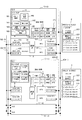
- FIG. 1 is a diagram illustrating a configuration example of a computer system according to the present embodiment.
- a computer system includes a plurality of computers used as servers (hereinafter referred to as “cluster”) 1 (1-0 to 1-3), two HW (HardWare) consoles 2 and 3, and an integrated system.
- a console 6 is provided.
- the integrated console 6 and each cluster 1 are connected to, for example, two LANs (Local Area Networks) 5 (5-0 and 5-1).
- the HW consoles 2 and 3 and each cluster 1 are connected to, for example, two LANs 4 (4-0 and 4-1). Both the HW consoles 2 and 3 correspond to data processing devices in the computer system according to the present embodiment.
- the integrated console 6 is a console for managing (including operations) the entire computer system.
- the management function of the integrated console 6 is provided by an SVPM (SerVice Processor Manager) 6 a mounted on the integrated console 6.
- SVPM Session Processor Manager
- the integrated console 6 and each cluster 1 are connected to two LANs 5 for fault tolerance.
- LAN 5 is used for data communication between clusters 1.
- the HW console 2 is, for example, an LSC (Local System Console) arranged in a room where each cluster 1 is installed.
- the HW console 3 is an RSC (Remote System Console) arranged in a place other than the room where each cluster 1 is installed.
- Both the HW consoles 2 and 3 are management (maintenance) consoles for each cluster 1.
- the HW console 2 and each cluster 1 can communicate via the LAN 4-0, and the HW console 3 and each cluster 1 can communicate via the LAN 4-1. As a result, each cluster 1 can be managed even if a failure occurs in one of the HW consoles 2 and 3 or one of the LANs 4-0 and 4-1.
- the HW consoles 2 and 3 include LAN interfaces 21 and 31 that enable communication via the LAN 4, respectively.
- “LSC-IP” and “RSC-IP” shown in FIG. 1 represent IP (Internet Protocol) addresses for communication via the LAN interfaces 21 and 31, respectively.
- Each cluster 1 corresponds to a computer according to the present embodiment, and includes SVP (SerVice Processor) 11 and two SCA (SVP Communication Adapter) 12 and 13.
- the SVP 11 is a processing device that enables management of the cluster 1 using the HW consoles 2 and 3.
- the SVP 11 of each cluster 1 uses the virtual IP address 14 for communication with the HW consoles 2 and 3.
- Each SCA 12 and 13 is provided with two LAN interfaces to enable communication via LANs 4 and 5, respectively.
- the SCA 12 enables communication via LANs 5-0 and 4-0 through two LAN interfaces.
- the SCA 13 enables communication via the LANs 5-1 and 4-1, using two LAN interfaces.
- “CL0-SVP-IP0” and “CL0-CSL-IP0” written on the SCA 12 represent the IP address of the SCA 12 for performing communication via the LAN 5-0 and 4-0, respectively.
- “CL0-SVP-IP1” and “CL0-CSL-IP1” written on the SCA 13 represent IP addresses of the SCA 13 for performing communication via the LANs 5-1 and 4-1, respectively.
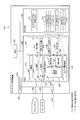
- FIG. 2 is a diagram for explaining a configuration example of a cluster according to the present embodiment.
- the cluster 1 has a configuration in which two SSUs (System ⁇ 2Storage Unit) 156 and two input / output devices (indicated as “I / O” in FIG. 2) are connected to the main body 10.
- SSUs System ⁇ 2Storage Unit
- I / O input / output devices
- main body 10 In the main body 10, in addition to the SVP 11 and the two SCAs 12 and 13, a system board (denoted as “SYSBD” in FIG. 2) 152 is mounted.
- SYSBD system board
- the system board 152 includes a plurality of CPUs (Central Processing Units) 152a and a plurality of memory modules (indicated as “DIMM” in FIG. 2; DIMM is an abbreviation for Dual Inline Memory Memory Module) 152b and functions as a single computer. To do. Although only one is shown in FIG. 2, a plurality of system boards 152 are usually mounted on the cluster 1.
- CPUs Central Processing Units
- DIMM Dual Inline Memory Memory Module
- the system board 152 is supplied with a clock from a clock generator (denoted as “CLK” in FIG. 2) 153.
- CLK clock generator
- the system board 152 accesses the two SSUs 156 via an SSX (System Storage Extender) 155 (155-0, 155-1) and an SSM (System Storage Mover) 154.
- the system board 152 uses a CHU (CHannel Unit) 158 and an IOP (Input / Output Processor) 157 of different systems for accessing the two input / output devices 159, respectively.
- CHU CHannel Unit
- IOP Input / Output Processor
- the system board 152, the clock generator 153, the SSM 154, and each IOP 157 are connected to an SCI (System Console15Interface) 151.
- the SCI 151 provides an interface for the connected SVP 11 to control or communicate with them.
- the SVP 11 includes an MPU (Micro-Processing Unit) 111, a RAM (Random Access Memory) 112, a DPRAM (Dual Port RAM) 113, an MDA (Micro Disk Adapter) 114, an SCIA (SCI Adapter) 115, and a bus 116 to which they are connected.
- MPU Micro-Processing Unit
- RAM Random Access Memory
- DPRAM Double Port RAM
- MDA Micro Disk Adapter
- SCIA SCI Adapter
- the SCA 12 includes an MPU 121, a RAM 122, and two LAN interfaces 123 and 124.
- the SCA 13 includes an MPU 131, a RAM 132, and two LAN interfaces 133 and 134.
- each CPU 152a of the system board 152 obtains and executes a program stored in, for example, one of the two SSUs 156, thereby causing the cluster 1 to function as a server. Communication between the clusters 1 and communication with the HW console 2 or 3 is performed via the SCA 12 or 13. Each CPU 152 a is connected to the SCAs 12 and 13, and transmits / receives data to / from another cluster 1 via the SCA 12 or 13.
- the MPU 111 of the SVP 11 provides a function as the SVP 11 by reading a program from the flash memory 117 via the MDA 114, storing it in the RAM 112, and executing it.
- the programs stored in the RAM 112 include a message transfer program 161 and a console connection control program 162.
- the message transfer program 161 is a program for realizing transmission of messages to the HW console 2 or 3 via the other cluster 1 and transfer of messages received from the other cluster 1 to the HW console 2 or 3.
- the console connection control program 162 is a program that enables only one cluster 1 among the plurality of clusters 1-0 to 1-3 to communicate with the HW console 2 or 3.
- the computer according to the present embodiment is realized by the MPU 111 of the SVP 11 executing at least the console connection control program 162.
- the console connection control program 162 (and the message transfer program 162) may be stored in a recording medium other than the flash memory 117, or may be received via the LAN 5 or the like.
- the DPRAM 113 stores a console connection status table 171.
- the console connection status table 171 is a table for managing communication with the HW consoles 2 and 3 by the SCAs 12 and 13.
- the console connection status table 171 stores data for managing communication with the HW consoles 2 and 3 via the LAN interfaces 124 and 134 of the SCAs 12 and 13 (hereinafter referred to as “console connection status data”).
- the cluster configuration table 163 stored in the RAM 112 is a table for specifying the communication state with the HW consoles 2 and 3 for each cluster 1. This cluster configuration table 163 stores the console connection status data of the HW consoles 2 and 3 for each cluster 1.
- the storage area of the DPRAM 113 is divided depending on, for example, the use. More specifically, for example, the storage area of the DPRAM 113 is divided according to combinations (SVP11 ⁇ SCA12, SVP11 ⁇ SCA13, SCA12 ⁇ SVP11, SCA13 ⁇ SVP11) for inputting / outputting data (messages), data types, and the like. As a result, data is input / output between the SVP 11 and the SCA 12 and between the SVP 11 and the SCA 13 via the DPRAM 113.
- the console connection status table 171 is stored in the DPRAM 113. Therefore, the MPUs 121 and 131 of the SCAs 12 and 13 can directly access the console connection status table 171.
- the MPU 121 of the SCA 12 monitors the corresponding storage area of the DPRAM 113, for example, and processes the data stored in the storage area. By the data processing, message transmission via the LAN interface 123 or 124 is realized. Each LAN interface 123 and 124 stores the received message in, for example, the RAM 122 and notifies the MPU 121 of the reception of the message. When the notification is made, the MPU 121 reads the message stored in the RAM 122 and stores it in the corresponding storage area of the DPRAM 113. Thereby, the SVP 11 acquires the received message.
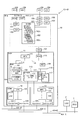
- FIG. 3 is a diagram illustrating a configuration example of the HW console.
- the HW console 2 has a configuration in which a display 240 and a keyboard 250 are connected to the display control device 200.
- the display control apparatus 200 includes an MPU 201, an NVRAM (Non Volatile RAM) 202, a RAM 203, an input / output controller 204, a keyboard interface 205, a display interface 206, and a LAN interface 21.
- the NVRAM 202 which is a non-volatile memory, stores load data 211, a gateway table 212, a server IP address 213, and a local IP address 214 that are read by the MPU 201 into the RAM 203.
- the gateway table 212, the server IP address 213, and the own IP address 214 are setup information for the HW console 2 to communicate with each cluster 1 via the LAN 4-0.
- the load data 211 includes a control program 220 executed by the MPU 201 and a data unit 230 used for processing.
- the control program 220 includes an initialization program 221, an output control program 222, an input control program 223, a LAN communication control program 224, and a setup information update program 225 as subprograms.
- the LAN communication control program 224 includes a data transmission / reception control program 226, a gateway selection control program 227, and a connection control program 228 as subprograms.
- the initialization program 221 is a program that performs initialization at power-on (startup).
- the output control program 222 is a program that outputs data (screen) to the display 240.
- the input control program 223 is a program for inputting data in response to an operation on the keyboard 250.
- the LAN communication control program 224 is a program for performing communication with each cluster 1 via the LAN 4-0.
- the setup information update program 225 is a program for updating the setup information stored in the NVRAM 202.
- the gateway selection control program 227 is a program for selecting the cluster 1 (the SCA 12) that actually performs communication among the plurality of clusters 1.
- the connection control program 228 is a program for managing the communication state with the cluster 1, that is, whether or not the cluster 1 that has established communication exists.
- the data section 230 includes screen information 231, character pattern information 232, a used gateway number 233, and connection state information 234.
- the screen information 231 is information for displaying a screen on the display 240.
- the character pattern information 232 is information for arranging characters (character strings), symbols and the like to be arranged on the screen displayed on the display 240.
- the used gateway number 233 is information for managing the cluster 1 that is currently establishing communication, and is updated by the gateway selection control program 227 of the LAN communication control program 224.
- the connection state information 234 is information indicating whether or not the cluster 1 that has established communication exists, and is updated by the connection control program 228 of the LAN communication control program 224.
- the gateway table 212 is a table that stores IP addresses assigned to the SCA 12 of each cluster 1. “Gateway 0” to “Gateway 3” shown in FIG. 3 represent numbers (gateway numbers) assigned to the SCAs 12 of the clusters 1-0 to 1-3, respectively.
- the server IP address 213 is a virtual IP address 14 used for communication with the SVP 11 of each cluster 1.
- the own IP address 214 includes an IP address assigned to the HW console 2 and a MAC (Media Access Control) address that is an ID (IDentifier) number of the LAN interface 21.
- the MPU 201 When the power is turned on, the MPU 201 reads the load data 211 from the NVRAM 202, stores it in the RAM 203, and starts executing the control program 220 of the load data 211. After starting the execution of the control program 220, the MPU 201 performs control corresponding to the operation of the operator on the keyboard 250 or the reception of a message by the LAN interface 21.
- HW consoles 2 and 3 data processing devices having the same configuration can be used.
- the HW console 3 is assumed to have the configuration shown in FIG.
- the computer system according to the present embodiment is constructed by using the four clusters 1 and the two HW consoles 2 and 3 as described above.
- the configuration of the computer system is not limited to that shown in FIG.
- the configurations of the cluster 1 and the HW consoles 2 and 3 are not limited to the configurations shown in FIG. 2 or FIG.
- each HW console 2 and 3 needs to establish communication with only one cluster 1 at the same time (in parallel).
- the protocol is adopted.
- the number of clusters 1 in which the HW consoles 2 and 3 can simultaneously establish communication is limited to one.
- a method for realizing such restriction will be described in detail with reference to FIGS.
- FIG. 4 is a diagram for explaining a method of restricting clusters that establish communication with each HW console.
- connection is used hereinafter to mean establishment of communication, that is, a state where communication can be performed.
- connection the establishment (connection) of communication between the HW console 2 and the cluster 1 is performed by transmitting a connection request that is a message requesting connection from the HW console 2 side.
- Selection (change) of the cluster 1 to be connected is normally performed by an operator.
- the output control program 222 of the control program 220 outputs a screen for the operator to select the cluster 1 on the display 240, and the cluster 1 selected on the screen is recognized by the input control program 223.
- the recognition result is notified to the LAN communication control program 224 in the form of a gateway number, for example.
- the gateway selection control program 227 of the LAN communication control program 224 reads out the IP address of the gateway number notified from the input control program 223 from the gateway table 212, and sets the IP address as the destination address of the message.
- the gateway number is stored as the used gateway number 233 of the data unit 230 by the gateway selection control program 227.
- the notification of the gateway number from the input control program 223 means that the operator has instructed switching of the connected cluster 1. Therefore, the connection control program 228 of the LAN communication control program 224 terminates communication with the cluster 1 when there is a currently connected cluster 1 by the notification of the gateway number, and the other cluster. 1 transmits a connection path switching instruction which is a message notifying that communication with 1 is established. Thereafter, the connection control program 228 transmits a connection request to the cluster 1 to which the notified gateway number is assigned. By transmitting the connection request, the HW console 2 establishes communication with the cluster 1 selected by the operator. The actual message transmission / reception is performed by the data transmission / reception control program 226.
- the use gateway number 233 is updated by the gateway selection control program 227 when the cluster 1 to establish communication is determined or when communication with the determined cluster 1 is established.
- the connection control program 228 stores a value representing a state connected to the cluster 1 as the connection state information 234. If communication with the cluster 1 selected by the operator is not established, the gateway selection control program 227 does not update the used gateway number 233. At this time, the connection control program 228 stores a value representing a state not connected to the cluster 1 as the connection state information 234.
- the value indicating the state connected to the cluster 1 is “1” and the value indicating the state not connected to the cluster 1 is “0”.
- the HW console 2 always operates to establish communication with only one cluster 1.
- One cluster 1 operates autonomously so that only one cluster 1 is connected to the HW console 2 even if the HW console 2 operates inappropriately.
- the cluster configuration table 163 and the console connection status table 171 are used for autonomous operation.
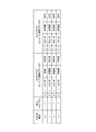
- the console connection status table 171 is used for managing connections with the HW consoles 2 and 3 by the LAN interfaces 124 and 134 of the SCAs 12 and 13. As shown in FIG. 4, the console connection status data includes an adapter number, an interface (IF) number, an IP address, connection status information, and connection permission information.
- IF interface
- IP address IP address
- connection status information connection permission information
- the adapter number is identification information assigned to each of the SCAs 12 and 13, and “0” represents the SCA 12, and “1” represents the SCA 13, respectively.
- the interface numbers are identification information assigned to the two LAN interfaces provided in the SCAs 12 and 13, respectively. “0” represents the LAN interfaces 123 and 133, and “1” represents the LAN interfaces 124 and 134, respectively.
- the IP address is used as identification information indicating a target to which the plurality of clusters 1 should restrict connections.
- “LSC-IP” and “RSC-IP” shown in FIG. 4 represent the IP addresses of the HW consoles 2 and 3, respectively.
- the connection status information is information indicating whether or not the HW console 2 (or 3) is connected. “0” indicates no connection and “1” indicates connection.
- the connection permission information is information indicating whether or not the connection with the HW console 1 (or 3) can be performed. “0” indicates that the connection cannot be performed and “1” indicates that the connection can be performed. Yes.
- connection not permitted state Each cluster 1 has a state in which it is not activated (hereinafter referred to as “stopped state”). If this stop state is included, there are four communication states in each cluster 1 in total.
- FIG. 4 shows console connection status data stored in the console connection status table 171 as (0, 1, LSC-IP, not connected, not permitted) and (1, 1, RSC-IP, not connected, allowed). Is written. Because of the above, (0, 1, LSC-IP, not connected, not permitted) means that the communication target using the LAN interface 124 of the SCA 12 is the HW console 2 and the communication state is the connection not permitted state. It represents something. Further, (1, 1, RSC-IP, unconnected, permitted) indicates that the communication target using the LAN interface 134 of the SCA 13 is the HW console 3, and the communication state is the connection permitted state.
- the console connection status data is data representing the communication state with the assumed communication target.
- the console connection data is used for managing the communication state of the own cluster 1 and for recognizing the communication state of other clusters 1.
- the cluster configuration table 163 is used for recognizing the communication state of the other cluster 1.
- FIG. 5 is a diagram for explaining an example of the contents of the cluster configuration table.
- the cluster configuration table 163 stores two console connection status data of each cluster 1.
- the two console connection status data are stored in the cluster configuration table 163 in a form of being integrated into one record (entry) for each cluster 1.
- the console connection status data for the LAN interface 124 of the SCA 12 is expressed as “console connection status of SCA0-IF1”.
- the console connection status data for the LAN interface 134 of the SCA 13 is described as “SCA1-IF1 console connection status”.
- Each record stores cluster number and input status information in addition to two console connection status data.
- the cluster number is identification information assigned to each cluster 1.
- the cluster number matches the gateway number, for example.
- the turn-on status information is information indicating whether or not the corresponding cluster 1 is turned on. “0” indicates that the power is not turned on, and “1” indicates that the power is turned on (in operation). Thereby, whether or not each cluster 1 is in a stopped state can be determined from the input status information.
- the console connection status data for the LAN interface 124 of the SCA 12 of each cluster 1 indicates that only one cluster 1 (here, cluster 1-0) is connected, and all the other clusters 1-1 to 1-3 are not connected. Indicates that it is in a permitted state. Accordingly, in a situation where one cluster 1 is in a connected state, all the other clusters 1 cannot be connected to the HW console 2.
- the console connection status data for the LAN interface 134 of the SCA 13 of each cluster 1 indicates that all the clusters 1 are in a connection permission state.
- all the clusters 1 can be connected to the HW console 2.
- the communication state of each cluster 1 is represented by the console connection status data for the LAN interface 124 of the SCA 12 of each cluster 1.
- the cluster configuration table 163 stores information for recognizing the communication state for each cluster 1. Therefore, each cluster 1 can recognize the communication state of the other cluster 1 by referring to the cluster configuration table 163. Accordingly, not only the limitation that only one cluster 1 can be connected to the HW console 2, but also the limitation that only a plurality of predetermined clusters 1 can be connected to the HW console 2 is referred to the cluster configuration table 163. Can be realized.
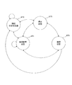
- FIG. 6 is a diagram for explaining the transition of the communication state of each cluster.
- Each cluster 1 before starting is in the stopped state ST0, and by starting, each cluster 1 acquires two types of console connection status data of the other cluster 1, and connection permission state ST1 or connection non-permission state ST2 Migrate to More specifically, the activated cluster 1 shifts to the connection permission state ST1 when the cluster 1 in the connection state ST3 does not exist, and does not permit the connection when the cluster 1 in the connection state ST3 exists. Move on to ST2.
- Cluster 1 that has transitioned to the connection state ST3 notifies the other cluster 1 to that effect.
- the cluster 1 having shifted to the connection state ST3 ends the connection, the cluster 1 notifies the other cluster 1 to that effect, and shifts to the connection permission state ST1 or the connection non-permission state ST2. For this reason, each cluster 1 recognizes the existence of the cluster 1 in the connection state ST3 among the other clusters 1.
- the cluster 1 in the connection state ST3 is hereinafter also referred to as “first cluster”.
- the transition from the connection state ST3 to the connection non-permission state ST2 is performed when the connection path switching instruction is received, that is, when the cluster 1 to which the HW console 2 is connected is switched.
- each cluster 1 When each cluster 1 recognizes the transition to the connection state ST3 of the other cluster 1, it shifts to the connection non-permission state ST2.
- the connection non-permission state ST2 is maintained until it is confirmed that the first cluster 1 which is the cluster 1 of the connection state ST3 does not exist. Therefore, only one first cluster 1 can exist at the same time.
- Each cluster 1 that has recognized the transition from the connection state ST3 of another cluster 1 to the connection permission state ST1 shifts from the connection non-permission state ST2 to the connection permission state ST1. Therefore, any of the plurality of clusters 1 can establish communication with the HW console 2. Thereby, the operator can connect the HW console 2 to the desired cluster 1.
- Each cluster 1 shifts to the stop state ST0 from any of the connection permission state ST1, the connection disapproval state ST2, and the connection state ST3 due to a power-off instruction or a failure. Thereby, in this embodiment, each cluster 1 performs state transition as shown in FIG.
- Each cluster 1 recognizes the communication state of the other cluster 1 and performs state transition as shown in FIG. 6, so that only one cluster 1 can establish communication simultaneously with the HW console 2 in each cluster 1. Limited to When one cluster 1 shifts to the connection state ST3, one cluster 1 that is not the first cluster 1 monitors other clusters 1 including the first cluster 1, and detects the cluster 1 that does not operate normally. Confirm and reflect the confirmation result to the state transition. As a result, in a situation where there is no cluster 1 in the connection state ST3 and no cluster 1 in the connection permission state ST1, all the other clusters 1 in operation are moved to the connection permission state ST1, and the HW console 2 Enables connection. For this reason, even if the first cluster 1 does not operate normally due to a power-off or failure, the operator can connect the HW console 2 to any other cluster 1. Can do.
- the state transition as described above is realized by the MPU 111 of the SVP 11 of each cluster 1 executing the console connection control program 162.
- the console connection control program 162 includes a path switching program 181, an on / off program 182, a console connection path monitoring program 183, a console communication state monitoring program 184, and a status update program 185 as subprograms.
- the path switching program 181 is a program for connecting to the HW console 2 or terminating the connection.
- the on / off program 182 is a program for responding to power-on and power-off (disconnection) of the cluster 1.
- the console connection path monitoring program 183 is a program for monitoring whether or not the other first cluster 1 is operating normally.
- the console communication status monitoring program 184 monitors whether or not communication with the HW console 2 can be performed when the own cluster 1 is connected to the HW console 2, that is, whether or not the HW console 2 is operating normally. It is a program to do.
- the status update program 185 is a program for updating the console connection status data in the cluster configuration table 163 and the console connection status table 171 by receiving a message from another cluster 1 or the like.
- the SVP 11 that executes the path switching program 181 notifies the other cluster 1 of the transition of the communication state due to the transition from the connection permission state ST1 to the connection state ST3 and the transition from the connection state ST33 to the connection permission state. Such notification is processed by the SVP 11 by executing the status update program 185, and the console connection status data in the cluster configuration table 163 and the console connection status table 171 is updated.
- the SVP 11 that executes the path switching program 181 refers to the cluster configuration table 163 and transitions from the connection permission state ST1 to the connection state ST3, that is, establishes communication with the HW console 2.
- the recognition of the other cluster 1 connected to the HW console 2 is realized by the SVP 11 executing at least the path switching program 181 and the status update program 185.
- Management so that only a predetermined number (here, one) of clusters 1 can be connected to the HW console 2 is realized by the SVP 11 executing the path switching program 181.
- the operation of the cluster 1 is performed by paying attention to the SVP 11, that is, the message transfer program 161 or the console connection control program 162.
- the operation of the HW console 2 is performed while paying attention to the control program 220. Accordingly, the operation will be described by focusing on the part related to the connection between the HW console 2 and the cluster 1.
- the message transfer program 161 and the console connection control program 162 are read from, for example, the flash memory 117 to the RAM 112 and executed by the MPU 111 of the SVP 11.
- the control program 220 is read from the NVRAM 202 to the RAM 203 and executed by the MPU 201.
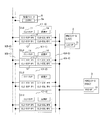
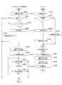
- FIG. 7 is a flowchart showing the flow of processing related to connection with the HW console executed by the activated cluster.
- the activated cluster indicated as “power-on cluster” in FIG. 7
- another cluster that has been activated that is, in operation (indicated as “other cluster that has been activated” in FIG. 7) is executed.
- a flowchart of the process is also shown. As a result, referring to FIG. 7 first, when one cluster 1 is activated, processing related to connection with the activated cluster 1 and the HW console 2 executed by the other active cluster 1 respectively. This will be described in detail.
- cluster 1-0 is activated as cluster 1 and cluster 1-1 is assumed as another cluster 1 that has already been entered.
- the processing of the SVP 11 of the cluster 1-0 shown in FIG. 7 is mainly realized by the insertion / disconnection program 182.
- the processing of the SVP 11 of the cluster 1-1 is mainly realized by the status update program 185.
- arrows arranged between processing steps executed in different clusters 1 indicate directions in which messages are transmitted and received. The same applies to FIGS. 10 to 15.
- An instruction to power on and power off each cluster 1 can be performed from the HW console 2 and the integrated console 6.
- the activated SVP 11 of the cluster 1-0 uses the LAN interface 123 of the SCA 12 to transmit a cluster power-on notification, which is a message notifying that power has been turned on, to the other clusters 1-1 to 1-3 ( SA1).
- the cluster power-on notification is transmitted to all the clusters 1 whose cluster numbers are stored on the cluster configuration table 163.
- a cluster power-on notification is received by the LAN interface 123 of the SCA 12 (SB1).
- the received cluster power-on notification is output from the SCA 12 to the SVP 11, and the SVP 11 updates the input status information of the corresponding record in the cluster configuration table 163.
- the update is performed by storing “1” as the value of the input status information (SB2).
- the SVP 11 uses the LAN interface 123 of the SCA 12 to transmit a cluster power-on notification response to the cluster 1-0 (SB3).
- Two types of console connection status data stored in the console connection status table 171 are added to the response and transmitted to the cluster 1-0.
- a series of processes due to the reception of the cluster power-on notification of the SVP 11 of the cluster 1-1 is terminated by transmitting a response.
- This process is repeatedly executed (SA2 to SA4). More specifically, the SVP 11 determines whether or not a specified time has elapsed in SA2. If the specified time has not elapsed, the determination of SA2 is No, and then the SVP 11 obtains the received response from the SCA 12 (SA3), and the console connection status data added to the response to the cluster configuration table 163 Reflection is performed (SA4). After the reflection, the process proceeds to SA2, and it is determined again whether the specified time has elapsed. If the specified time has elapsed, the determination of SA2 is Yes and the process proceeds to SA5.
- the value of the input status information of each record in the cluster configuration table 163 is “0”, and no console connection status data is stored.
- the SVP 11 of the cluster 1-0 stores the two types of console connection status data added to the response in corresponding records on the cluster configuration table 163 of the cluster 1-1 that has received the response.
- the value of the input status information of the record is updated to “1”. In this way, for each received response, the record corresponding to the response in the cluster configuration table 163 is updated.
- the value of the input status information of a record that does not receive a response remains “0”. In this manner, the activated cluster 1-0 transmits all the cluster power-on notifications to each of the clusters 1-1 to 1-3, and all of the active clusters 1-1 to 1-3 are operating. The communication state of cluster 1 will be confirmed.
- the SVP 11 refers to the cluster configuration table 163 and determines whether or not the cluster 1 in the connection state ST3 exists. If any of the console connection status data of the HW console 2 stored in the cluster configuration table 163 indicates the connection state ST3, the determination is Yes. In this case, the SVP 11 generates console connection status data with the communication state of the own cluster 1-0 as the connection not-permitted state ST2, and stores the generated status data in the console connection status table 171 and the cluster configuration table 163, respectively ( SA7).
- the SVP 11 determines whether there is no data representing the connection state ST3 in the console connection status data of the HW console 2 stored in the cluster configuration table 163, the determination of SA5 is No.
- the SVP 11 generates console connection status data with the communication state of the own cluster 1-0 as the connection permission state ST1, and stores the generated status data in the console connection status table 171 and the cluster configuration table 163, respectively (SA6). ).
- the series of processing for responding to activation by the SVP 11 of the cluster 1-0 is completed by storing the console connection status data. Thereafter, the SVP 11 updates the cluster configuration table 163 or the console connection status table 171 as necessary.
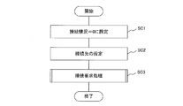
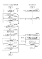
- FIG. 8 is a flowchart of processing executed when the HW console is powered on. Next, with reference to FIG. 8, a process executed for connection with the cluster 1 when the HW console 2 is turned on, that is, when it is activated will be described in detail.
- the processing shown in FIG. 8 is mainly realized by the initialization program 221 of the control program 220 and the LAN communication control program 224.
- the HW console 2 stores “0”, which is a value indicating a state of being not connected to the cluster 1, as the connection state information 234 (SC1).
- the HW console 2 refers to the gateway table 212 and sets (stores) the gateway number stored in the first entry (record) as the used gateway number 233 (SC2).
- SC3 connection request process
- connection request process executed in SC3 is a process for specifying a connectable cluster 1 and connecting to the specified cluster 1.
- the setting of the used gateway number 233 in SC2 is performed as an initial setting for executing the connection request processing.
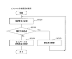
- FIG. 9 is a flowchart of the connection request process.
- the HW console 2 reads the used gateway number 233, and transmits a connection request, which is a message requesting establishment of communication, to the LAN interface 21 using the IP address assigned with the gateway number 233 as a transmission destination (SC121). .
- the HW console 2 determines whether or not a specified time has elapsed before receiving a response (SC122). If a response is received before the specified time has elapsed, the determination in SC122 is NO. In that case, the HW console 2 updates the value of the connection state information 234 to 1 (SC124). Thereafter, the connection request process ends.
- the HW console 2 updates the used gateway number 233 to the gateway number of the next entry in the gateway table 212 (SC123). Thus, after setting the cluster 1 as the connection destination, the process returns to the SC121.
- the HW console 2 transmits the connection request while changing the cluster 1 as the connection request transmission destination until it is connected to the cluster 1. Thereby, the HW console 2 connects to the connectable cluster 1 at the time of activation.
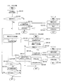
- FIG. 10 is a flowchart showing the flow of processing related to the connection with the HW console executed by the cluster that turns off the power. This process is executed when a power-off instruction is given from the HW console 2 or the integrated console 6, for example.
- a cluster to be turned off in addition to a cluster to be turned off (indicated as “cluster to be turned off” in FIG. 10), another cluster that has been turned on (indicated as “other turned on cluster” in FIG. 10), and A flowchart of processing executed by the HW console 2 is also shown.
- FIG. 10 when one cluster 1 turns off the power, the cluster 1 that turns off the power, the other cluster 1 that has been turned on, and the processing executed by the HW console 2 respectively This will be described in detail.
- the cluster 1 to be turned off is the cluster 1-0
- the other cluster 1 that has been turned on is the cluster 1-1.
- the processing of the SVP 11 of the cluster 1-0 shown in FIG. 10 is mainly realized by the insertion / disconnection program 182.
- the processing of the SVP 11 of the cluster 1-1 is mainly realized by the status update program 185.
- the SVP 11 of the cluster 1-0 instructed to turn off the power from the HW console 2 or the integrated console 6 first refers to the console connection status data of the own cluster 1-0 to determine whether the value of the connection status information is 1 or not. (SA11).
- SA11 When communication with the HW console 2 is established, the value of the connection status information is “1”. For this reason, when communication with the HW console 2 is established, the determination of SA11 is Yes and the process proceeds to SA12. On the other hand, when communication with the HW console 2 is not established, the determination of SA11 is No and the process proceeds to SA19.
- the console connection status data of the own cluster 1-0 is console connection status data stored in the console connection status table 171.
- the SVP 11 sets both values of the connection status information and the connection permission information in the console connection status data of the own cluster 1-0 to “0”.
- the SVP 11 causes the SCA 12 to transmit a connection disconnection request, which is a message for requesting the end of communication, to the HW console 2 (SA13).
- the HW console 2 receives the connection disconnection request transmitted from the cluster 1-0 (SC11).
- the HW console 2 that has received the connection disconnection request sets the value of the connection status information 234 of its own console 2 to “0” (SC12), and transmits a response to the cluster 1-0 (SC13).
- the HW console 2 executes the connection request process described above (SC14). By executing the connection request process, the HW console 2 ends a series of processes by receiving the connection disconnection request.
- the SVP 11 of the cluster 1-0 after transmitting the connection disconnection request waits to receive a response to the connection disconnection request from the HW console 2 (SA14). When the response is received, the SVP 11 then sends a console message that indicates that communication with the HW console 2 has been completed to all the clusters 1 whose power is turned on in the cluster configuration table 163. A disconnection notice is transmitted (SA15).
- the SVP 11 of the cluster 1-1 receives the received console disconnection notification via the SCA 12 (SB11).
- the SVP 11 sets each value of the connection status information and the connection permission information in the console connection status data on the console connection status table 171 to “0” and “1”, and shifts to the connection permission state ST1.
- the SVP 11 sets each value of the connection status information and the connection permission information in the console connection status data of all the clusters 1 on the cluster configuration table 163 to “0” and “1” (SB13). Thereafter, the SVP 11 transmits a response to the cluster 1-0 (SB14).
- the SVP 11 of the cluster 1-0 after transmitting the console disconnection notification executes a process for responding to a response received until the specified time elapses (SA16 to SA18).
- the transition to SA19 is performed when the determination of SA16 becomes Yes when the specified time elapses, or when the determination of SA18 becomes Yes by receiving all responses before the specified time elapses.
- the SVP 11 transmits a cluster power-off notification, which is a message for notifying that all the clusters 1 whose power is turned on in the cluster configuration table 163 are turned off. (SA19).
- the SVP 11 of the cluster 1-1 receives the cluster power-off notification received by the SCA 12 (SB15). Next, the SVP 11 updates the value of the entry status information of the corresponding entry in the cluster configuration table 163 to “0” (SB16). Thereafter, the SVP 11 sends a response to the cluster 1-0 (SB17). By transmitting the response, a series of processing for responding to power-off in cluster 1-0 is completed.
- the SVP 11 of the cluster 1-0 after transmitting the cluster power-off notification executes processing for responding to the response received until the specified time has elapsed (SA20 to SA22).
- the transition to SA23 is performed when the determination of SA20 becomes Yes when the specified time elapses, or when the determination of SA22 becomes Yes by receiving all responses before the specified time elapses.
- the SVP 11 executes a process for turning off the power of the cluster 1-0. Through this process, the system board 152 is instructed to shut down. A series of processing at the time of power-off ends after confirming the shutdown of the system board 152.
- the cluster 1-0 that cuts off the power notifies the other clusters 1 that are in operation to cut off the power. If the connection with the HW console 2 is in progress, the cluster 1-0 disconnects the connection with the HW console 2, updates the console connection status data of the own cluster 1-0, and disconnects the connection with the HW console 2. To all the other clusters 1 in operation. Therefore, the cluster 1 to which these notifications are performed can appropriately update the data including the console connection status data stored in each entry of the cluster configuration table 163. As a result, when the cluster 1 connected to the HW console 2 is turned off, any other cluster 1 in operation can cope with the connection to the HW console 2.
- FIG. 11 is a flowchart of console connection processing executed by the cluster for connection with the HW console.
- one other cluster 1 that does not execute this console connection process (indicated as “other cluster already loaded” in FIG. 11) and the HW console 2 execute each.
- a flowchart of the processing is also shown. Accordingly, referring to FIG. 11, when one cluster 1 executes the console connection process, the other cluster 1 that has been turned on (in operation) and the process that the HW console 2 executes are also executed. A detailed description will also be given.
- the cluster 1 that executes the console connection process is the cluster 1-0
- the other cluster 1 that has already been input is the cluster 1-1.
- the processing of the SVP 11 of the cluster 1-0 shown in FIG. 11 is realized mainly by the path switching program 181, for example.
- the processing of the SVP 11 of the cluster 1-1 is mainly realized by the status update program 185.
- the processing of the HW console 2 is mainly realized by the LAN communication control program 224.
- the console connection process is executed when the SVP 11 of the cluster 1 that has received the connection request from the HW console 2 receives the connection request.
- the HW console 2 transmits a connection request to the cluster 1-0 to establish communication (SC31).
- the connection request transmitted from the HW console 2 is received by the SCA 12 of the cluster 1-0 and passed to the SVP 11 (SA31).
- SA31 the SVP 11 refers to the console connection status table 171 stored in the DPRAM 113 and determines whether or not the value of the connection permission information in the corresponding console connection status data is “1” (SA32).
- SA32 the console connection status table 171 stored in the DPRAM 113 and determines whether or not the value of the connection permission information in the corresponding console connection status data is “1” (SA32).
- SA32 the value of the connection permission information is “1”. Therefore, in this case, the determination of SA32 is Yes and the process proceeds to SA33. Otherwise, that is, when the own cluster 1-0 is in the connection non-permission state ST2, the determination of SA32 is No, and a series of processing ends here. Thereby, the transition from the connection non-permission state ST2 to the connection
- the SVP 11 determines whether or not the IP address in the corresponding console connection status data matches the IP address of the HW console 2 that is the transmission source of the connection request. If they match, the determination of SA33 is Yes and the process proceeds to SA35. If they do not match, the determination at SA33 is No and the process proceeds to SA34.
- the SVP 11 decides not to send a response when it receives a connection request from outside the connection target. Thereafter, the series of processing is terminated. On the other hand, in SA35, the SVP 11 transmits a response to the transmission source of the connection request using the SCA 12.
- the HW console 2 after transmitting the connection request executes processing for responding to the response to the connection request (SC32 to SC35). As a result, if the HW console 2 receives a response before the specified time has elapsed (Yes in SC32 ⁇ SC33), the communication status with the cluster 1-0 has been established, and the value of the connection status information 234 is “1”. Is stored (SC34). On the other hand, when the response is not received before the specified time has elapsed (No in SC32), the HW console 2 stores “0” as the value of the connection state information 234 (SC35). After such connection state information 234 is updated, a series of processing relating to the connection with the cluster 1-0 is completed.
- the SC31 to SC35 executed by the HW console 2 correspond to the parts realized by the SC121, SC122, and SC124 in the connection request processing shown in FIG. Although not shown in FIG. 9, SC35 is executed before moving to SC123, for example, when the determination of SC122 is Yes.
- the SVP 11 of the cluster 1-0 after transmitting the response to the HW console 2 updates the console connection status table 171 and the cluster configuration table 163, assuming that communication with the HW console 2 has been established (SA36).
- the console connection status data of the own cluster 1-0 is updated in accordance with the transition to the connection state ST3, and the console connection status data of the other cluster 1 is updated in accordance with the transition to the connection non-permission state ST2. Is done.
- the SVP 11 transmits a console connection notification, which is a message for notifying that communication with the HW console 2 has been established, to all the other clusters 1 that have recognized the power-on (SA37).
- the SVP 11 of the cluster 1-1 acquires the console connection notification received from the cluster 1-0 from the SCA 12 (SB31). Upon acquisition of the console connection notification, the SVP 11 updates the console connection status data in the console connection status table 171 (SB32), and reflects the update in the cluster configuration table 163 (SB33). Thereafter, the SVP 11 transmits a response to the cluster 1-0 that is the transmission source of the console connection notification (SB34). By transmitting the response, a series of processes relating to the transition of the cluster 1-0 to the connection state ST3 is completed. The console connection status data is updated in accordance with the transition of the cluster 1-1 to the connection non-permission state ST2.
- the SVP 11 of the cluster 1-0 after transmitting the console connection notification executes processing for responding to the response received until the specified time has elapsed (SA38 to SA40).
- the process is performed until the determination of SA38 becomes Yes when the specified time elapses, or until the determination of SA40 becomes Yes by receiving all responses before the specified time elapses.
- the console connection process ends after it is determined Yes in SA38 or SA40.
- the cluster 1 that has transitioned to the connection state ST3 notifies the other cluster 1 of the transition, and the other cluster 1 has the console connection status of each cluster 1 including its own cluster 1 to respond to the notification. Update the data. For this reason, under the situation where the cluster 1 in the connection state ST3 exists, all the other clusters 1 are in the connection non-permission state ST2. Thereby, it is avoided that two or more clusters 1 simultaneously enter the connection state ST3.
- FIG. 12 is a flowchart of connection path switching processing executed by the cluster to switch connection with the HW console.
- This connection path switching process is a process executed by the cluster 1 when a new connection destination is notified from the HW console 2.
- FIG. 12 in addition to the flowchart of the connection path switching process, the flowchart of the process executed by the cluster 1 which is the new connection destination (indicated as “path switching destination cluster” in FIG. 12), and the HW console 2 execute A flowchart of the processing is also shown. Accordingly, referring to FIG. 12, when one cluster 1 executes the connection path switching process, the details of the process executed by each of the new connection destination cluster 1 and the HW console 2 are also described. Explained.
- the first cluster 1 that executes the connection path switching process is the cluster 1-0
- the new connection destination cluster 1 is the cluster 1-1.
- the connection path switching process illustrated in FIG. 12 is mainly realized by the path switching program 181.
- the processing of the SVP 11 of the cluster 1-1 is mainly realized by the status update program 185.
- connection path switching process is executed to cause the currently connected cluster 1 to disconnect and prepare another cluster 1 to connect to the HW console 2.
- the HW console 2 transmits to the currently connected cluster 1 a connection path switching instruction which is a message for instructing preparation for newly connecting to another cluster 1.
- a code (for example, a cluster number) representing the new connection destination cluster 1 is added to the connection path switching instruction so that the newly connected cluster 1 can be identified.
- the newly connected cluster 1 is selected according to an instruction via the operator's keyboard 250.
- the output control program 222 executed by the HW console 2 displays a screen for switching the connection destination cluster 1.
- the input control program 223 analyzes the operator's operation on the keyboard 250, recognizes the instruction content of the operator, and passes the recognition result to the LAN communication control program 224.
- the gateway selection control program 227 acquires an IP address for communicating with the cluster 1 from the gateway table 212 in accordance with an operator instruction.
- the connection control program 238 transmits a connection path switching instruction to the currently connected cluster 1. From this, the processing of the HW console 2 shown in FIG. 12 is mainly realized by the connection control program 238.
- the HW console 2 transmits a connection path switching instruction to the currently connected cluster 1-0 (SC51).
- the HW console 2 sets a new connection destination (SC52).
- SC52 the gateway number of the new connection destination is stored as the used gateway number 233.
- the value of the connection state information 234 is updated to “0”.
- the used gateway number 233 is updated by the gateway selection control program 227, and the snow image state information 234 is updated by the connection control program 238.
- connection path switching instruction transmitted from the HW console 2 is received by the SCA 12 of the cluster 1-0 and passed to the SVP 11 (SA51).
- the SVP 11 identifies the corresponding entry in the cluster configuration table 163 based on the code added to the connection path switching instruction, and confirms the input status information of the identified entry (SA52). Thereafter, the SVP 11 determines whether or not the value of the input status information is “1”.
- the cluster 1-1 designated by the code is operating, the value “1” is stored in the cluster configuration table 163 as the input status information of the cluster 1-1. Therefore, when the cluster 1-1 is operating, the determination of SA53 is Yes and the process proceeds to SA54. If the cluster 1-1 is not operating, the determination of SA53 is No and the process proceeds to SA60.
- the SVP 11 transmits to the cluster 1-1 a path switching request that is a message for requesting a transition to a state where connection to the HW console 2 is possible.
- the SCA 12 receives the path switching request, and the received path switching request is passed from the SCA 12 to the SVP 11 (SB51).
- the SVP 11 that has received the path switching request updates the console connection status data on the console connection status table 171 in order to shift to the connection permission state ST1 (SB52), and reflects the update in the cluster configuration table 163 (SB53). .
- the SVP 11 transmits a response to the cluster 1-0 (SB54). By transmitting the response, a series of processes by receiving the path switching request is completed.
- the SVP 11 in the cluster 1-0 waits to receive a response after transmitting the path switching request (SA55). Upon receipt of the response, the SVP 11 updates the console connection status data in the console connection status table 171 (SA56) and reflects the update in the cluster configuration table 163 (SA57) in order to shift to the connection non-permission state ST2.
- the SVP 11 causes the HW console 2 to transmit a connection disconnection request that is a message for requesting disconnection of the connection (SA58). After transmitting the disconnection request, the SVP 11 waits to receive a response (SA59). When the response is received, the connection path switching process ends.
- the HW console 2 receives the connection disconnection request transmitted from the cluster 1-0 (SC61).
- the HW console 2 that has received the connection disconnection request updates the value of the connection state information 234 to “0” (SC62), and transmits a response to the cluster 1-0 (SC63).
- the HW console 2 executes a connection process for establishing communication with the cluster 1-1 designated by the operator (SC64). By executing this connection process, a series of processes by receiving the connection disconnection request is completed.
- the HW console 2 executes SC31 to SC35 shown in FIG.
- the connection request is transmitted using the IP address acquired from the gateway table 212 by the gateway selection control program 227 according to the operator's instruction.
- the HW console 2 establishes communication with the cluster 1-1 selected by the operator.
- the cluster 1-1 after transmitting the response in the SB 54 receives the connection request from the HW console 2 by executing the connection process in the SC 64 of the HW console 2. Since the processing for responding to the connection request has been described in detail with reference to FIG. 11, the description thereof is omitted here.
- the determination of No in SA53 means that the HW console 2 has transmitted a connection path switching instruction specifying the cluster 1-1 that is not in operation. Therefore, in SA60, the SVP 11 of the cluster 1-0 sends an error message output request to the HW console 2 which is a message requesting notification to the operator that the connected cluster 1 cannot be switched by the connection path switching instruction. Send. The subsequent SVP 11 waits to receive a response from the HW console 2 (SA61). Upon receiving the response, the connection path switching process ends.
- the HW console 2 receives the error message output request transmitted from the cluster 1-0 (SC71).
- the HW console 2 that has received the error message output request displays an error message on the display 240 for notifying that the connection with the cluster 1-1 designated by the operator cannot be performed (SC72). Thereafter, the HW console 2 transmits a response to the cluster 1-0 (SC73). By transmitting the response, a series of processes by receiving the error message output request is completed.
- the output of the above error message allows the operator to recognize that connection with the selected cluster 1-1 cannot be made. Therefore, it is possible to immediately start work for another cluster 1.
- the output of the alarm message is performed by the output control program 222 in response to a request from the data transmission / reception control program 226.
- the alarm message data to be output is generated using, for example, character pattern information 232.
- the cluster 1 connected to the HW console 2 shifts the cluster 1 specified by the code to a state where it can be connected to the HW console 2, and then disconnects from the HW console 2. It is supposed to be.
- the connection is disconnected in such a procedure by checking whether or not the cluster 1 can connect to the HW console 2 through communication with the cluster 1 specified by the code, and the check result is used to disconnect the connection. This is because it is reflected in By adopting such a procedure, if the cluster 1 specified by the cord cannot be connected to the HW console 2 due to power-off or failure, it is connected to another cluster 1 through the currently connected cluster 1 Can be prepared for.
- the processing of SA54 to SA59 and the cluster 1-1 and the HW console 2 by SA54 to SA59 are executed when the switching succeeds and the connection path switching instruction can be processed normally.
- the SA60 to SA61 and the processing of the HW console 2 by the SA60 to SA61 are executed when switching fails.
- the cluster 1-1 that transmitted the path switching request is not operating normally. In that case, the cluster 1-1 does not transmit a response. For this reason, if the SVP 11 of the cluster 1-0 fails to receive a response before the stipulated time elapses in SA55, it notifies the HW console 2 to that effect and maintains the connection state ST3. SA56 to SA59 are not executed. In this way, a state in which the next connection path switching instruction can be received is maintained.
- the cluster 1-0 that disconnects the connection with the HW console by receiving the connection path switching instruction does not notify the other cluster 1 of the fact. This is because the cluster 1-1 that is next connected to the HW console 2 notifies the other cluster 1 of the connection. This is because the notification means that the connection of the cluster 1-0 is disconnected. This means that the cluster 1 that disconnects the connection does not necessarily have to notify the other cluster 1 of the disconnection.
- the HW console 2 is not always operating normally. There may be a case where the HW console 2 is not operating normally due to a power cut or failure. Therefore, in the present embodiment, the connected cluster 1 is monitored at any time as to whether or not communication with the HW console 2 can be performed. As a result, when it is confirmed that communication with the HW console 2 cannot be performed, all the operating clusters 1 are shifted to the connection permission state ST1.
- the HW console 2 When the HW console 2 returns to the normal operation state by shifting all the operating clusters 1 to the connection permission state ST1, the HW console 2 can be connected to any cluster 1. As a result, when the HW console 2 comes to operate normally, the operator can immediately connect the HW console 2 to the desired cluster 1, so that a reduction in work efficiency and the like can be suppressed.
- FIG. 13 is a flowchart of the console monitoring process.
- This console monitoring process is executed to monitor whether or not the cluster 1 connected to the HW console 2 (shown as “cluster connected to the console” in FIG. 13) can communicate with the HW console 2.
- This process is executed at a predetermined timing, for example. More specifically, the console monitoring process is executed on condition that, for example, communication with the HW console 2 has not been performed for a predetermined time or more.
- FIG. 13 also shows a flowchart of processing executed by the HW console 2 and another cluster 1 that is not connected, in addition to the flowchart of console monitoring processing. Accordingly, with reference to FIG. 13, the processing executed by the HW console 2 and the other clusters 1 when the connected cluster 1 executes the console monitoring processing will be described in detail.
- the cluster 1 that executes the console monitoring process that is, the first cluster 1 is the cluster 1-0 and the other cluster 1 is the cluster 1-1.
- the console monitoring process shown in FIG. 13 is realized mainly by the console communication state monitoring program 184.
- the processing of the SVP 11 of the cluster 1-1 is mainly realized by the status update program 185.
- the SVP 11 of the cluster 1-0 transmits a status notification request, which is a message used for checking the operation state, to the HW console 2 (SA81).
- a status notification request which is a message used for checking the operation state
- the HW console 2 receives the transmitted status notification request (SC81) and transmits a response (SC82).
- the SVP 11 of the cluster 1-0 waits to receive a response until the specified time elapses after transmitting the status notification request (SA82, SA83). As a result, if a response is received before the specified time has elapsed since the status notification request was transmitted (No in SA82 ⁇ SA83), the HW console 2 is considered to be operating normally, and the console monitoring process is performed here. Ends. On the other hand, if the response is not received before the specified time has elapsed after the status notification request is transmitted (Yes in SA82), the HW console 2 is regarded as not operating normally, and the process proceeds to SA84.
- the SVP 11 updates the console connection status data on the console connection status table 171 in order to shift to the connection permission state ST1.
- the SVP 11 reflects the update in the cluster configuration table 163 (SA85).
- the SVP 11 transmits a console disconnection notification, which is a message for notifying that the connection with the HW console 2 has been disconnected, to all the clusters 1 that can be confirmed to be operating from the cluster configuration table 163 (SA86).
- the SVP 11 after transmitting the console disconnection notification executes a process for responding to a response received until the specified time has elapsed (SA87 to SA89).
- the processing is performed until the determination of SA87 becomes Yes when the specified time elapses, or until the determination of SA89 becomes Yes by receiving all responses before the specified time elapses.
- the console monitoring process ends after it is determined Yes in SA87 or SA89.
- the SVP 11 of the cluster 1-1 not connected to the HW console 2 receives the console disconnection notification received from the cluster 1-0 via the SCA 12 (SB81).
- the SVP 11 updates the console connection status data on the console connection status table 171 to shift to the connection permission state ST1 (SB82), and reflects the update in the cluster configuration table 163 ( SB83).
- the SVP 11 transmits a response to the cluster 1-0 (SB84). By transmitting the response, a series of processes by receiving the console disconnection notification is completed.
- the cluster 1 connected to the HW console 2 checks whether or not the HW console 2 operates normally. If the HW console 2 does not operate normally, all the clusters 1 that are operating are connected. Is shifted to the connection permission state ST1. Therefore, the HW console 2 that has returned to a normal operating state can be connected to an arbitrary cluster 1.
- Cluster 1 may not work properly, including cluster 1 connected to HW console 2.
- the cluster 1 connected to the HW console 2 does not operate normally for some reason or communication with the other cluster 1 cannot be performed, all the other clusters 1 operating in the other operation state enter the connection non-permission state ST2. is there. Therefore, in this case, the operator cannot connect the HW console 2 to another cluster 1.
- the cluster 1 that is not connected to the HW console 2 is made to monitor whether or not such a situation has occurred. As a result, when such a situation occurs, all the operating clusters 1 are shifted to the connection permission state ST1.
- the migration it is possible to avoid the situation where the HW console 2 cannot be connected to the cluster 1, and the computer system can be operated more stably.
- the cluster 1 connected to the HW console 2 must perform processing in response to a request from the HW console 2. Therefore, there is a high possibility that the load is heavier than that of the cluster 1 that is not connected to the HW console 2. For this reason, in the present embodiment, the monitoring is performed by the cluster 1 that is not connected to the HW console 2. The monitoring may be performed by the cluster 1 connected to the HW console 2.
- FIG. 14 is a flowchart of the console connection path monitoring process.
- This console connection path monitoring process is a process executed by the cluster 1 that is not connected to the HW console 2 to monitor the operating state of the other cluster 1 that is recognized as operating. Is executed. More specifically, the console connection path monitoring process is executed every time a predetermined time elapses, for example, in any of the clusters 1 that are not connected to the HW console 2.
- the console connection path monitoring process is executed in cluster 1 with a low execution frequency or a long elapsed time since the console connection path monitoring process was executed in order to avoid the execution frequency from greatly differing depending on the cluster 1 It is desirable to let them.
- FIG. 14 also shows a flowchart of processing executed by another cluster 1 in operation (denoted as “other cluster already entered” in FIG. 14) in addition to the flowchart of the console connection path monitoring process. Accordingly, with reference to FIG. 14, a process executed by another cluster 1 when one cluster 1 executes the console connection path monitoring process will be described in detail.
- the cluster 1 for executing the console connection path monitoring process is the cluster 1-0 and the other cluster 1 is the cluster 1-1.
- the console connection path monitoring process shown in FIG. 14 is mainly realized by the console connection path monitoring program 183.
- the processing of the SVP 11 of the cluster 1-1 is mainly realized by the status update program 185.
- the SVP 11 of the cluster 1-0 transmits a console connection status request, which is a message for requesting transmission of console connection status data, to all other clusters whose power-on can be confirmed on the cluster configuration table 163. (SA101). Thereafter, the SVP 11 executes a process for responding to a response received until the specified time elapses (SA102 to SA104). The process is performed until the determination of SA102 becomes Yes when the specified time elapses, or until the determination of SA104 becomes Yes by receiving all responses before the specified time elapses. When it is determined Yes in SA102 or SA104, the process proceeds to SA105.
- the SVP 11 of the cluster 1-1 to which the console connection status request has been transmitted receives the received console connection status request via the SCA 12 (SB101).
- the SVP 11 adds the console connection status data of the own cluster 1-1 stored in the console connection status table 171 to the response and transmits it (SB102).
- the SVP 11 of the cluster 1-0 that has transmitted the console connection status request can recognize the communication state of each cluster 1 that has transmitted the response by receiving the response.
- the SVP 11 determines whether there is a cluster 1 being connected or connectable from the received response.
- the absence of the cluster 1 in the connection state ST3 or the connection permission state ST1 means that neither the cluster 1 currently connected to the HW console 2 nor the cluster 1 connectable to the HW console 2 exists. Therefore, if neither cluster 1 in connection state ST3 nor cluster 1 in connection permission state ST1 exists, the determination in SA105 is No and the process proceeds to SA106. If the cluster 1 in the connection state ST3 or the cluster 1 in the connection permission state ST1 exists, the determination in SA105 is Yes, and the console connection path monitoring process ends here.
- the SVP 11 updates the console connection status data of its own cluster 1-0 in order to set the connection permission state ST1, and assumes a setting of the connection permission state ST1 of each cluster 1 that has received the response. 163 is updated.
- the SVP 11 transmits a cluster configuration table notification, which is a message to which the console connection status data of each cluster 1 stored in the updated cluster configuration table 163 is added, to all the clusters 1 that have received the response (SA107). .
- the SVP 11 executes a process for responding to a response received until the specified time elapses (SA108 to SA110).
- the processing is performed until the determination of SA108 becomes Yes when the specified time elapses, or until the determination of SA110 becomes Yes by receiving all responses before the specified time elapses.
- the console connection path monitoring process ends.
- the SVP 11 of the cluster 1-1 to which the cluster configuration table notification has been transmitted receives the received cluster configuration table notification via the SCA 12 (SB103).
- the SVP 11 Upon receiving the cluster configuration table notification, the SVP 11 stores all console connection status data added to the cluster configuration table notification in the cluster configuration table 163 (SB104).
- the SVP 11 reflects the console connection status data of the own cluster 1-1 in the console connection status table 171 (SB105).
- the SVP 11 transmits a response to the cluster 1-0 (SB106). By transmitting the response, a series of processes corresponding to the execution of the console connection path monitoring process by the SVP 11 of the cluster 1-0 is completed.
- the series of processing ends after execution of the SB102.
- an alarm message output request which is a message for notifying the operator of the contents of the information, is sent to the HW console 2 to the cluster 1 where the information to be notified to the operator has occurred. Yes.
- the unconnected cluster 1 is configured to transmit an alarm message output request via the connected cluster 1.
- the transfer of the alarm message output request via the connected cluster 1 enables all the clusters 1 to transmit the alarm message output request to the HW console 2 in a timely manner when necessary.
- FIG. 15 is a flowchart of the alarm message output process.
- This alarm message output process is a process executed to transmit the alarm message output request directly or indirectly to the HW console 2 when an alarm message output request to be transmitted to the HW console 2 occurs. .
- the cluster 1 can directly or indirectly transmit necessary data to the HW console 2.
- FIG. 15 also shows a message transfer process executed by the cluster 1 connected to the HW console 2 and a process executed by the HW console 2 in addition to the flowchart of the alarm message output process.
- the message transfer process is a process executed to transfer an alarm message output request to the HW console 2 in response to a request from the cluster 1 that is not connected. Accordingly, referring to FIG. 15 at the end, when the unconnected cluster 1 executes the alarm message output process, the details of the process executed by the connected cluster 1 and the HW console 2 are also described. Explained.
- the cluster 1-0 is the cluster 1 that executes the alarm message output process
- the cluster 1-1 is the other cluster 1 that executes the message transfer process.
- the alarm message output process shown in FIG. 15 is mainly realized by the message transfer program 161.
- the message transfer process executed by the SVP 11 of the cluster 1-1 is mainly realized by the message transfer program 161.
- the processing executed by the HW console 2 is mainly realized by the data transmission / reception control program 226.
- the SVP 11 of the cluster 1-0 that is in a situation where an alarm message output request should be transmitted first sets (substitutes) an initial value for the number of retries (SA131).
- the number of retries is actually a variable for counting the number of times that another cluster 1 has been requested to transfer an alarm message output request, and its initial value is, for example, “0”.
- the number of transfer requests is counted up to a preset upper limit by counting the number of transfer requests.
- the SVP 11 determines whether or not the value of the connection status information of the console connection status data of the own cluster 1-0 is “1”. When connected to the HW console 2, “1” is set as the value of the connection status information. For this reason, when connected to the HW console 2, the determination of SA132 is Yes and the process proceeds to SA133. When not connected to the HW console 2, the determination of SA133 is No and the process proceeds to SA135.
- the SVP 11 transmits an alarm message output request to the HW console 2.
- the SVP 11 waits to receive a response from the HW console 2 (SA134). After receiving the response, the alarm message output process ends.
- the HW console 2 to which the alarm message output request has been transmitted receives the alarm message output request (SC131).
- the HW console 2 that has received the alarm message output request causes the display 240 to output an alarm message specified by the alarm message output request (SC132). Thereafter, a series of processes related to reception of the alarm message output request is completed.
- the output of the alarm message is performed by the output control program 222 in response to a request from the data transmission / reception control program 226.
- the alarm message data to be output is generated using, for example, character pattern information 232.
- the SVP 11 of the cluster 1-0 that has shifted to SA135 with the SA132 determination being No refers to the cluster configuration table 163 and confirms the cluster 1-1 that is connected to the HW console 2.
- the SVP 11 transmits an alarm message transfer request, which is a message for requesting transfer of an alarm message output request, to the confirmed cluster 1-1 (SA136).
- the alarm message output request is added to the alarm message transfer request and transmitted to the cluster 1-1.
- the SVP 11 of the cluster 1-1 receives the alarm message transfer request received by the SCA 12 from the SCA 12 (SB131). Receiving the alarm message transfer request, the SVP 11 checks the console connection status data of its own cluster 1-1 (SB132), and determines whether the value of the connection status information is “1” (SB133). When the value of the connection status information is “1”, that is, when the own cluster 1-1 is connected to the HW console 2, the determination of SA133 is Yes and the process proceeds to SB134. When the value of the connection status information is not “1”, the determination of SA133 is No and the process proceeds to SB137.
- the SVP 11 causes the HW console 2 to transmit an alarm message output request added to the alarm message transfer request.
- the SVP 11 that has transmitted the alarm message output request waits to receive a response from the HW console 2 (SB135).
- the SVP 11 transmits a response storing an end status indicating that the transfer of the alarm message output request has been normally completed to the cluster 1-0 (SB136). By transmitting the response, the message transfer procedure is completed.
- the SVP 11 transmits a response storing an end status indicating that an error has occurred in the transfer of the alarm message output request to the cluster 1-0. By transmitting the response, the message transfer procedure is completed.
- the SVP 11 of the cluster 1-0 after transmitting the alarm message transfer request waits to receive a response from the cluster 1-1 (SA137).
- the SVP 11 determines whether or not the end status of the received response indicates normal (SA138). If the end status indicates normal, the determination of SA138 is Yes, and the alarm message output process ends here. If the end status does not indicate normal, the determination of SA138 is No and the process proceeds to SA139.
- the SVP 11 adds 1 to the number of retries.
- the SVP 11 determines whether the number of retries is within a specified number (SA140). If the number of retries is within the specified number of times, that is, if the number of requests for transferring an alarm message output request to another cluster 1 by sending an alarm message transfer request has not reached the upper limit, the determination of SA140 is Yes. Return to SA135. Thereby, an alarm message transfer request is transmitted again. On the other hand, if the number of retries is greater than the specified number, the determination in SA140 is No and the message output process ends here.
- the cluster 1 in a situation where an alarm message output request should be transmitted transmits an alarm message output request to the HW console 2 directly or indirectly depending on whether or not it is connected to the HW console 2. Therefore, for the operator, the state of each cluster 1 in operation can be grasped in a timely manner regardless of whether or not the HW console 2 is connected.
- each cluster 1 recognizes the communication state of the other cluster 1 and shifts the communication state of its own cluster 1, but the cluster 1 that recognizes the communication state of each cluster 1 is limited. You may do it. That is, one or more clusters 1 that recognize the communication state of each cluster 1 and manage the transition of the communication state of other clusters 1 may be prepared. This means that the control for shifting the communication state may be performed on either the notification transmission side or the notification reception side.
- the recognition of the cluster 1 connected to the HW console 2 is notified at the time of transition to the connection state ST3 and at the time of transition from the connection state ST3 to the connection permission state ST1 when the normal operation of the HW console 2 cannot be confirmed. It is supposed to be done by. However, the timing at which notifications are transmitted, the order in which notifications are transmitted, and the like are not limited to the present embodiment. They can be variously modified.
Landscapes
- Engineering & Computer Science (AREA)
- Theoretical Computer Science (AREA)
- Signal Processing (AREA)
- Computer Networks & Wireless Communication (AREA)
- General Physics & Mathematics (AREA)
- Physics & Mathematics (AREA)
- General Engineering & Computer Science (AREA)
- Computer Security & Cryptography (AREA)
- Business, Economics & Management (AREA)
- General Business, Economics & Management (AREA)
- Multimedia (AREA)
- Health & Medical Sciences (AREA)
- Cardiology (AREA)
- General Health & Medical Sciences (AREA)
- Small-Scale Networks (AREA)
Abstract
Dans un système (1) auquel est appliquée l'invention, lorsqu'un changement survient dans un état de communication entre chaque ordinateur d'une pluralité d'ordinateurs et un appareil de traitement de données par le biais d'un réseau en raison de l'établissement ou de la cessation de la communication, l'ordinateur indique le changement de l'état de communication aux autres ordinateurs de la pluralité d'ordinateurs, ce qui permet aux autres ordinateurs de la pluralité d'ordinateurs d'identifier les premiers ordinateurs qui sont ceux de la pluralité d'ordinateurs qui ont établi la communication avec l'appareil de traitement de données. De cette façon, chaque ordinateur de la pluralité d'ordinateurs peut établir la communication en réponse à une demande de l'appareil de traitement de données à la condition que le nombre des premiers ordinateurs identifiés soit équivalent ou inférieur à un nombre prédéterminé.
Priority Applications (2)
| Application Number | Priority Date | Filing Date | Title |
|---|---|---|---|
| PCT/JP2011/069222 WO2013027298A1 (fr) | 2011-08-25 | 2011-08-25 | Procédé d'établissement de communication, système informatique et ordinateur |
| US14/183,578 US20140173120A1 (en) | 2011-08-25 | 2014-02-19 | Method for establishing communication, computer system, and computer |
Applications Claiming Priority (1)
| Application Number | Priority Date | Filing Date | Title |
|---|---|---|---|
| PCT/JP2011/069222 WO2013027298A1 (fr) | 2011-08-25 | 2011-08-25 | Procédé d'établissement de communication, système informatique et ordinateur |
Related Child Applications (1)
| Application Number | Title | Priority Date | Filing Date |
|---|---|---|---|
| US14/183,578 Continuation US20140173120A1 (en) | 2011-08-25 | 2014-02-19 | Method for establishing communication, computer system, and computer |
Publications (1)
| Publication Number | Publication Date |
|---|---|
| WO2013027298A1 true WO2013027298A1 (fr) | 2013-02-28 |
Family
ID=47746078
Family Applications (1)
| Application Number | Title | Priority Date | Filing Date |
|---|---|---|---|
| PCT/JP2011/069222 Ceased WO2013027298A1 (fr) | 2011-08-25 | 2011-08-25 | Procédé d'établissement de communication, système informatique et ordinateur |
Country Status (2)
| Country | Link |
|---|---|
| US (1) | US20140173120A1 (fr) |
| WO (1) | WO2013027298A1 (fr) |
Citations (2)
| Publication number | Priority date | Publication date | Assignee | Title |
|---|---|---|---|---|
| JP2007226398A (ja) * | 2006-02-22 | 2007-09-06 | Hitachi Ltd | データベース接続管理方法及び計算機システム |
| WO2009107649A1 (fr) * | 2008-02-29 | 2009-09-03 | コニカミノルタエムジー株式会社 | Système de gestion d'images médicales |
Family Cites Families (3)
| Publication number | Priority date | Publication date | Assignee | Title |
|---|---|---|---|---|
| US7636323B2 (en) * | 2005-06-14 | 2009-12-22 | Broadcom Corporation | Method and system for handling connection setup in a network |
| JP4884132B2 (ja) * | 2006-08-17 | 2012-02-29 | 富士通株式会社 | 電話システム、接続制御方法、接続制御装置、及びコンピュータプログラム |
| JP5755639B2 (ja) * | 2010-04-14 | 2015-07-29 | パナソニック インテレクチュアル プロパティ コーポレーション オブアメリカPanasonic Intellectual Property Corporation of America | 接続確立方法及び通信ノード |
-
2011
- 2011-08-25 WO PCT/JP2011/069222 patent/WO2013027298A1/fr not_active Ceased
-
2014
- 2014-02-19 US US14/183,578 patent/US20140173120A1/en not_active Abandoned
Patent Citations (2)
| Publication number | Priority date | Publication date | Assignee | Title |
|---|---|---|---|---|
| JP2007226398A (ja) * | 2006-02-22 | 2007-09-06 | Hitachi Ltd | データベース接続管理方法及び計算機システム |
| WO2009107649A1 (fr) * | 2008-02-29 | 2009-09-03 | コニカミノルタエムジー株式会社 | Système de gestion d'images médicales |
Also Published As
| Publication number | Publication date |
|---|---|
| US20140173120A1 (en) | 2014-06-19 |
Similar Documents
| Publication | Publication Date | Title |
|---|---|---|
| JP5221251B2 (ja) | 記憶装置 | |
| JP5910246B2 (ja) | 情報処理システム及び仮想アドレス設定方法 | |
| JP2010233006A (ja) | サーバシステム、集合型サーバ装置及びmacアドレス管理方法 | |
| JP2014170394A (ja) | クラスタシステム | |
| US7499987B2 (en) | Deterministically electing an active node | |
| US20070266120A1 (en) | System and method for handling instructions in a pre-boot execution environment | |
| JP5531487B2 (ja) | サーバシステム及びサーバシステムの管理方法 | |
| JP2010092336A (ja) | ストレージシステム及び通信方法 | |
| JP4806382B2 (ja) | 冗長化システム | |
| JP2015007967A (ja) | 電力消費状態の変更を要求する少なくとも1つのパケットの少なくとも一部の受信および/または少なくとも一部の発行 | |
| WO2013027298A1 (fr) | Procédé d'établissement de communication, système informatique et ordinateur | |
| JPWO2013027298A1 (ja) | 通信確立方法、コンピュータシステム、及びコンピュータ | |
| JP2010033506A (ja) | 二重化システム、および二重化システムにおける運用系決定方法 | |
| JP4893731B2 (ja) | 通信制御装置 | |
| JP2007280313A (ja) | 冗長化システム | |
| JP4816983B2 (ja) | ディスクアレイ装置、ディスクアレイ装置における電源制御方法及び電源制御プログラム | |
| JP5609272B2 (ja) | サーバ装置、サーバシステム及びサーバ装置の制御方法 | |
| JP2008204113A (ja) | ネットワーク監視システム | |
| JP4630234B2 (ja) | 二重系システム | |
| WO2014041625A1 (fr) | Dispositif de traitement d'informations et procédé de régulation d'alimentation électrique | |
| JP2009080780A (ja) | リモート電源制御装置 | |
| JP2009169708A (ja) | 入出力制御装置 | |
| JP4871832B2 (ja) | 計算機システム | |
| CN102480386A (zh) | 伺服器机柜系统及其启动方法、伺服器启动方法 | |
| CN118524107B (zh) | 一种双节点高可用集群避免脑裂的方法及系统、存储介质 |
Legal Events
| Date | Code | Title | Description |
|---|---|---|---|
| 121 | Ep: the epo has been informed by wipo that ep was designated in this application |
Ref document number: 11871355 Country of ref document: EP Kind code of ref document: A1 |
|
| ENP | Entry into the national phase |
Ref document number: 2013529830 Country of ref document: JP Kind code of ref document: A |
|
| NENP | Non-entry into the national phase |
Ref country code: DE |
|
| 122 | Ep: pct application non-entry in european phase |
Ref document number: 11871355 Country of ref document: EP Kind code of ref document: A1 |