WO2013027996A2 - Transmission par chaîne elliptique asymétrique pour un vélo - Google Patents
Transmission par chaîne elliptique asymétrique pour un vélo Download PDFInfo
- Publication number
- WO2013027996A2 WO2013027996A2 PCT/KR2012/006634 KR2012006634W WO2013027996A2 WO 2013027996 A2 WO2013027996 A2 WO 2013027996A2 KR 2012006634 W KR2012006634 W KR 2012006634W WO 2013027996 A2 WO2013027996 A2 WO 2013027996A2
- Authority
- WO
- WIPO (PCT)
- Prior art keywords
- ellipse
- gear
- point
- angle
- asymmetric
- Prior art date
- Legal status (The legal status is an assumption and is not a legal conclusion. Google has not performed a legal analysis and makes no representation as to the accuracy of the status listed.)
- Ceased
Links
Images







Classifications
-
- F—MECHANICAL ENGINEERING; LIGHTING; HEATING; WEAPONS; BLASTING
- F16—ENGINEERING ELEMENTS AND UNITS; GENERAL MEASURES FOR PRODUCING AND MAINTAINING EFFECTIVE FUNCTIONING OF MACHINES OR INSTALLATIONS; THERMAL INSULATION IN GENERAL
- F16H—GEARING
- F16H55/00—Elements with teeth or friction surfaces for conveying motion; Worms, pulleys or sheaves for gearing mechanisms
- F16H55/02—Toothed members; Worms
- F16H55/30—Chain-wheels
-
- B—PERFORMING OPERATIONS; TRANSPORTING
- B62—LAND VEHICLES FOR TRAVELLING OTHERWISE THAN ON RAILS
- B62M—RIDER PROPULSION OF WHEELED VEHICLES OR SLEDGES; POWERED PROPULSION OF SLEDGES OR SINGLE-TRACK CYCLES; TRANSMISSIONS SPECIALLY ADAPTED FOR SUCH VEHICLES
- B62M9/00—Transmissions characterised by use of an endless chain, belt, or the like
- B62M9/04—Transmissions characterised by use of an endless chain, belt, or the like of changeable ratio
- B62M9/06—Transmissions characterised by use of an endless chain, belt, or the like of changeable ratio using a single chain, belt, or the like
- B62M9/08—Transmissions characterised by use of an endless chain, belt, or the like of changeable ratio using a single chain, belt, or the like involving eccentrically- mounted or elliptically-shaped driving or driven wheel; with expansible driving or driven wheel
-
- B—PERFORMING OPERATIONS; TRANSPORTING
- B62—LAND VEHICLES FOR TRAVELLING OTHERWISE THAN ON RAILS
- B62M—RIDER PROPULSION OF WHEELED VEHICLES OR SLEDGES; POWERED PROPULSION OF SLEDGES OR SINGLE-TRACK CYCLES; TRANSMISSIONS SPECIALLY ADAPTED FOR SUCH VEHICLES
- B62M3/00—Construction of cranks operated by hand or foot
- B62M3/06—Construction of cranks operated by hand or foot with elliptical or other non-circular rotary movement
-
- B—PERFORMING OPERATIONS; TRANSPORTING
- B62—LAND VEHICLES FOR TRAVELLING OTHERWISE THAN ON RAILS
- B62M—RIDER PROPULSION OF WHEELED VEHICLES OR SLEDGES; POWERED PROPULSION OF SLEDGES OR SINGLE-TRACK CYCLES; TRANSMISSIONS SPECIALLY ADAPTED FOR SUCH VEHICLES
- B62M9/00—Transmissions characterised by use of an endless chain, belt, or the like
- B62M2009/002—Non-circular chain rings or sprockets
Definitions
- the present invention relates to an asymmetrical elliptical chain gear of a bicycle.
- the distance between the crankshaft and the chain is increased in a section in which the force applied to the pedal is increased.
- the shape of a typical chain gear is circular. Circular chain gears are easy to manufacture and are most commonly used.
- the force exerted on the pedals while a person rides a bicycle depends on the position of the crank arm. In other words, when the chain is in contact with the shortest side, when the crank arm reaches 30-45 degrees with the seat tube combined with the saddle, the force applied to the pedal is extremely reduced, and the angle between the crank arm and the seat tube is about 165 degrees.
- the longest side where the driving inertia of the crank, the angular acceleration of the crank and the human body dynamics are combined to produce the greatest force is located. This principle of ergonomics is not considered in the circular chain gear at all, which reduces the driving efficiency of the bicycle.
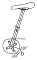
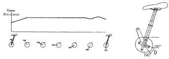
- US 5,549,314 has a simple circular trajectory with a constant value from 107 degrees to 143 degrees with respect to the shortest side as shown in Fig. 8a, and the crank has approximately the shortest side and about 18 degrees so that the position of the saddle when the chain is in contact with the shortest side.
- the crank is located at the point where the position of the crank and the crank coincide.
- crank position of US Pat. No. 5,549,314 is a mathematical driving dead center concept of the hip joint rather than a human driving dead center concept consisting of hip joint, knee joint, ankle joint, and the like.
- the configuration of 107 degrees adds the driving inertia of about 20 degrees to the angle and the maximum output point of the angle of less than 90 degrees, which is the characteristic of the general angle of the seat tube 18 degrees and tangential.
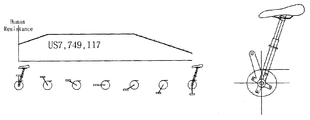
- US 7,749,117 is a symmetrical elliptical gear as shown in Fig. 9b, and the concept of correct human driving dead center which is the center of the knee joint as shown in Fig. 6a is set so that the dead point where the chain is located is 30-45 degrees with the saddle. Place it at ⁇ 130 degrees.
- the position of the longest side of the US7,749,117, the longest side of the saddle and 120 ⁇ 130 degrees, the position of the longest side of the real maximum output section of the human body applying acceleration and inertia in the present invention is much less than the saddle and 165 degrees, this
- the OCP system to overcome is to acknowledge the limitation of symmetric gear.
- the saddle is intended to maintain the body's bodily sensitization resistance from 11 to 6 o'clock in a general bicycle around 18 degrees.
- the present invention has been made in order to solve the above problems, the shape of the ellipse gear is determined by the combination of two ellipses and straight lines close to the vertical, while the distance between the crank shaft and the chain away from the force is greatly In order to reduce the distance between the crankshaft and the chain, it is possible to increase the driving efficiency but to provide smooth driving, easy to design, and to provide an asymmetric elliptical gear that reflects the principles of ergonomics. .
- the longest side and the shortest side angle may be less than 90 degrees
- the first ellipse of the angle b is set by the angle a.
- the longest side and the shortest side are difficult to exceed 120 degrees
- a second ellipse perpendicular to the first ellipse is created at a similar angle.
- the shortest side angle can easily exceed 120 degrees.
- the asymmetric elliptical chain gear according to the present invention includes a first ellipse in which a long axis is located on an X axis of a vertical coordinate system and a short axis is located on a Y axis, and a first straight line perpendicular to the short axis and intersecting the first ellipse ( 3) and the first inflection point (A, A ') which is on the first straight line and is located at a point that makes a constant angle (a) clockwise with respect to the short axis, and the constant angle clockwise at the long axis ( b) a shape is formed by a combination of second ellipses contacting the elliptic contact points (B, B ') on the first ellipse located at a point forming the second ellipse point (C), which is an intersection point of the first straight line and the first ellipse.
- the shape is formed by a combination of one ellipse section.
- the angle (c) formed by the second inflection point (C, C ') and the short axis may be designed not to be larger than the angle (a) between the first inflection point (A, A') and the short axis.
- the larger the angle c is the higher the resistance of the starting point of motion is.
- the lower angle c is, as shown in FIG. 11A, the lower the resistance of the starting point of exercise is.
- the angle a may be characterized in that it is 10 to 35 degrees, lowering the axis length angle a in Figure 10a to create an ellipse parallel to the similar angle and the angle between the longest side and the shortest side is less than 90 degrees 10b can be made in contact with the first ellipse of the angle b by setting the angle a as shown in Figure 10b, wherein the angle of the longest side and the shortest side is difficult to exceed 120 degrees, if the angle a is large as shown in Figure 10c A second ellipse perpendicular to the ellipse is formed at a similar angle, and the longest side and the shortest side angle can easily exceed 120 degrees.
- the angle b may be characterized in that it is 0 to 15 degrees, in the case that b is 0 in Figure 11b occurs a phenomenon that the body resistance decreases instantaneously, the long and short side angle is wider and the larger the angle b is the resistance The increase in congestion intervals is high and the long and short angles are narrowed.
- the gear interdental of the asymmetrical elliptical chain gear according to the present invention may be characterized in that the wide and narrow form is repeated.
- the index groove may be formed in a wide area of the gear tooth of the asymmetric elliptical gear.
- At least one clasp rivet may be coupled to a side portion adjacent to a gear tooth far from a center of the asymmetrical elliptical chain gear.
- Asymmetrical elliptical chain gear according to the present invention may be characterized in that the guard frame having a certain thickness is further coupled to one side of the asymmetric elliptic gear.
- the present invention overcomes the inefficiency of the symmetrical elliptic gear and maximizes the efficiency of the elliptical gear in consideration of the special characteristics such as the movement characteristics of the human body and the dancing driving and the angular acceleration of the crank, and the ineffective section according to the rotational position of the elliptical gear. At the same time, it has the effect of overcoming the problem of the narrow shift section of the symmetric elliptical gear.
- the NC machining is possible by providing a design standard of the asymmetrical elliptical chain gear, and has the advantage of facilitating the design of various elliptical gears suitable for the use of bicycles.
- each a, b, c should be organically applicable to the environment of use of the bicycle, and long and short side angles can be applied within the range of 115 ⁇ 135 degrees.
- the present invention can provide various asymmetric elliptical gears according to the use environment within a certain range of long and short side angles.
- FIG. 1 is a front view when the asymmetrical elliptical chain gear is coupled to a crank according to an embodiment of the present invention.
- Figure 2 is a front view when the asymmetrical elliptical chain gear is mounted according to an embodiment of the present invention.
- Figure 3 is a front view of an asymmetrical elliptical chain gear according to one embodiment of the present invention.
- Figure 4 is a front view of the guard frame of the asymmetrical elliptical chain gear in accordance with one embodiment of the present invention.
- FIG. 5 is an explanatory view for determining the shape of an asymmetrical elliptical chain gear according to an embodiment of the present invention.
- 6A to 6F are operation explanatory diagrams for explaining the dynamic relationship according to the rotation of the chain gear.
- Figure 7 is a further explanatory view for determining the shape of the asymmetrical elliptical chain gear according to an embodiment of the present invention.
- 8a to 8c are explanatory diagrams for explaining the dynamics of the rotation of the patent US 5,549,314.
- 9A to 9D are explanatory views for explaining the body resistance according to the rotation of the chain gear in the present invention and patents US5,549,314 and US Pat. No. 7,749,117.
- 10A to 10C are explanatory views of the basic requirements of the first ellipse and the second ellipse of the present invention.
- 11A to 11C are explanatory diagrams for explaining the body resistance according to the input of various elements of the present invention.
- FIG. 1 to 2 are front views when the asymmetrical elliptical chain gear 10 is mounted according to the preferred embodiment of the present invention
- FIG. 5 is a shape of the asymmetrical elliptical chain gear 10 according to the present invention. It is explanatory drawing to say.
- the asymmetrical elliptical chain gear 10 includes a first ellipse 1 having a long axis located on an X axis of a vertical coordinate system and a short axis located on a Y axis, and the short axis.
- a second ellipse 2 which contacts the elliptic contact point B, B 'on the first ellipse 1 positioned at a point passing through the first inflection point A and A' and forming a constant angle b in the clockwise direction from the long axis;
- the shape is formed by the combination of), the straight section (I) from the second inflection point (C) which is the intersection of the first straight line 3 and the first ellipse (1) and the first inflection point (A), and the A combination of a second ellipse section (J) from the first inflection point (A) to the elliptic contact point (B) and a first elliptic section (K) from the elliptic contact point (B) to the second inflection point (C ') shape It
- the vertical coordinate system is introduced for convenience to clearly explain the principle of determining the shape of the asymmetrical elliptical chain gear according to the present invention.
- all of the asymmetrical elliptical chain gears having the same or similar shape are the rights of the present invention. Will belong to the range.
- the term "elliptical shape" is a concept including a shape close to the ellipse and does not mean a mathematical ellipse.
- the eccentricity of the first ellipse 1 is not limited, but is preferably determined between about 1.05 and 1.25. If the eccentricity is too close to 1, there is no performance difference with the circular gear, and if the eccentricity is too large, shifting is difficult and a runny problem may occur during driving.
- the first straight line 3 is determined to be parallel to the long axis or perpendicular to the short axis and the distance H from the origin is less than or equal to the length d1 of the short side.
- the first straight line 3 is determined at a point where the distance from the origin is close to the length d1 of the short side so that the straight section of the elliptical gear is not too long.
- the intersection of the straight line 3 and the first ellipse 1 is defined as the second inflection point C.
- the first inflection point A is defined on the first straight line 3 and forms a constant angle a in a clockwise direction about the short axis and the origin. At this time, each a is preferably determined between 10 degrees to 35 degrees. If the angle a is too large, the straight section of the elliptical gear becomes too long and the shape of the elliptical gear is greatly distorted. If the angle a is too small, the difference is not different from that of the symmetric elliptic gear.
- An elliptical contact point B defines a point that forms a constant angle b in the clockwise direction with the long axis or the X axis and is positioned on the first ellipse 1. It is preferable to determine each b between 0 degrees and 20 degrees.
- the second ellipse 2 passing through the first inflection point A and contacting the first ellipse 1 at the elliptic contact point B is determined.
- the first ellipse 1, the second ellipse 2, and the first straight line 3 are determined in this way, as illustrated in FIG. 5, a pair of first to second inflection points C and C ′ is determined.
- the shape of is determined.
- the angle c formed by the second inflection point C and C 'and the short axis not be greater than the angle a formed by the first inflection points A and A' and short axis.
- the gear interdental of the asymmetrical elliptical chain gear 10 according to the present invention is preferably formed by repeating a wide and narrow shape.
- the force acting between the chain gear and the chain is not constant. Therefore, it is preferable to increase the closeness of the chain gear and the chain by repeating the wide and narrow shape between the gears.
- the first elliptic section and the second elliptic section of the asymmetric elliptical gear is to form an index groove 12 in a wider of the gear interval so that the chain can be smoothly shifted by the chain gear smoothly shifted. desirable.
- the asymmetrical elliptical chain gear 10 may be characterized in that at least one clasp rivet 13 is coupled to a side portion adjacent to a gear tooth far from the center of the asymmetrical elliptical chain gear. .
- Clasp 13 is to help the chain is caught naturally shifting when shifting. It is preferable to engage the clasp rivet 13 with a focus on a distance far from the center of the chain gear which is likely to not shift smoothly.
- the clasp rivets are formed in a wide interdental position.
- Asymmetrical elliptical chain gear according to the present invention may be characterized in that the guard frame 20 having a certain thickness is further coupled to one side of the asymmetric elliptical gear.
- the guard frame 20 serves to reinforce the strength of the chain gear and prevent the chain from being pinched between the chain gears.
- 6A to 6F are operational explanatory diagrams explaining the dynamic relationship according to the change of the position of the chain gear.
- FIG. 6a shows an angle between the crank arm 30 and the seat tube 40 when the chain is in contact with the shortest side, and forms a starting point of motion.
- the chain is placed in the straight section of the chain gear, or the distance between the chain and the crankshaft is shortest.
- the pedal is hard to apply, so the chain is on the shortest side so that you can drive the bike with less force.
- Figure 6b shows a state in which the angle between the arm of the crank and the seat tube is about 90 degrees. At this time, since the state is capable of applying a relatively strong force to the pedal ergonomically, the distance between the chain and the crankshaft is further accelerated and accelerated than in the state shown in FIG.
- FIG. 6C shows the crank arm almost horizontal to the ground. At this point, the acceleration becomes more active than the point shown in Fig. 6b, and the state can apply the strongest force to the pedal. The distance between the chain and the crankshaft is greater than the state shown in FIG. 6B.
- 6D is a state in which the chain gear and the crank arm are rotated more than the state shown in FIG. 6C.
- the force exerted on the pedal becomes weaker as you pass this point.
- the maximum force on the pedal is not the point, but given the increased inertia due to acceleration during the process described above, the chain is the point of greatest resistance and the saddle angle is 135-170 degrees. Therefore, the distance between the crankshaft and the chain is at this point maximum (h), and after this point the distance between the chain and the crankshaft becomes closer.
- the bicycle asymmetric elliptical chain gear according to the present invention is designed in consideration of both the magnitude of the force applied to the pedal and the angular acceleration of the crank and the driving inertia of the bicycle. It is to output power and at the same time allow smooth driving.
Landscapes
- Engineering & Computer Science (AREA)
- Mechanical Engineering (AREA)
- Chemical & Material Sciences (AREA)
- Combustion & Propulsion (AREA)
- Transportation (AREA)
- General Engineering & Computer Science (AREA)
- Gears, Cams (AREA)
Abstract
Selon la présente invention, une transmission par chaîne elliptique asymétrique (10) est caractérisée en ce qu'elle présente une forme formée d'une combinaison des éléments suivants : une première ellipse (1) dont l'axe majeur est situé sur l'axe X d'un système de coordonnées verticales et dont l'axe mineur est situé sur l'axe Y du système de coordonnées verticales ; une première ligne droite (3) qui est perpendiculaire à l'axe mineur et qui croise la première ellipse (1) ; et une seconde ellipse (2) qui existe sur la première ligne droite (3) et qui traverse des premiers points d'inflexion (A, A') qui forment un angle fixe (a) par rapport à l'axe mineur dans le sens des aiguilles d'une montre, et qui entre en contact avec des points de contact d'ellipse (B, B') sur la première ellipse (1) qui sont situés en des points formant un angle fixe (b) dans le sens des aiguilles d'une montre. La transmission par chaîne elliptique asymétrique (10) selon la présente invention présente une forme formée d'une combinaison d'une section de ligne droite comprise entre un second point de réflexion (C), qui est un point de croisement entre la première ligne droite (3) et la première ellipse (1), et le premier point d'inflexion (A) ; d'une seconde section d'ellipse comprise entre le premier point d'inflexion (A) et le point de contact d'ellipse (B) ; et d'une première section d'ellipse comprise entre le point de contact d'ellipse (B) et le second point d'inflexion (C').
Priority Applications (2)
| Application Number | Priority Date | Filing Date | Title |
|---|---|---|---|
| CN201280041248.1A CN103748003B (zh) | 2011-08-23 | 2012-08-21 | 自行车的非对称椭圆形链轮 |
| US14/240,414 US9074682B2 (en) | 2011-08-23 | 2012-08-21 | Asymmetric elliptical chain gear for a bicycle |
Applications Claiming Priority (2)
| Application Number | Priority Date | Filing Date | Title |
|---|---|---|---|
| KR20110083899 | 2011-08-23 | ||
| KR10-2011-0083899 | 2011-08-23 |
Publications (2)
| Publication Number | Publication Date |
|---|---|
| WO2013027996A2 true WO2013027996A2 (fr) | 2013-02-28 |
| WO2013027996A3 WO2013027996A3 (fr) | 2013-05-10 |
Family
ID=47746992
Family Applications (1)
| Application Number | Title | Priority Date | Filing Date |
|---|---|---|---|
| PCT/KR2012/006634 Ceased WO2013027996A2 (fr) | 2011-08-23 | 2012-08-21 | Transmission par chaîne elliptique asymétrique pour un vélo |
Country Status (3)
| Country | Link |
|---|---|
| US (1) | US9074682B2 (fr) |
| CN (1) | CN103748003B (fr) |
| WO (1) | WO2013027996A2 (fr) |
Cited By (1)
| Publication number | Priority date | Publication date | Assignee | Title |
|---|---|---|---|---|
| US9074682B2 (en) | 2011-08-23 | 2015-07-07 | Yun Seok Choi | Asymmetric elliptical chain gear for a bicycle |
Families Citing this family (15)
| Publication number | Priority date | Publication date | Assignee | Title |
|---|---|---|---|---|
| US9182027B2 (en) | 2011-12-06 | 2015-11-10 | Sram, Llc | Chainring |
| DE102013009492B4 (de) | 2013-06-05 | 2023-10-19 | Sram Deutschland Gmbh | Kettenring |
| DE102015219522B4 (de) * | 2014-10-14 | 2025-07-24 | Sram Deutschland Gmbh | Mehrfach-Kettenradanordnung für eine Hinterradnabe |
| WO2016203433A1 (fr) * | 2015-06-18 | 2016-12-22 | Antonello Briosi | Roue dentée pour systèmes de transmission de mouvement sur cycles |
| US10703441B2 (en) | 2015-07-03 | 2020-07-07 | Sram Deutschland Gmbh | Drive arrangement for a bicycle |
| DE102015008662A1 (de) * | 2015-07-03 | 2017-01-05 | Sram Deutschland Gmbh | Einzelkettenrad für eine Fahrradvorderkurbelanordnung |
| JP6757903B2 (ja) * | 2015-09-03 | 2020-09-23 | 株式会社スミス | 左右脚別にギヤ倍数を設けた非円形形状の自転車ギヤ |
| CA3029557A1 (fr) * | 2016-07-01 | 2018-01-04 | Move Bikes Gmbh | Roue dentee pour transmission de bicyclette |
| KR102041551B1 (ko) * | 2016-10-06 | 2019-11-27 | 최윤석 | 클립리스 페달을 위한 비대칭 타원체인링 |
| TWI593598B (zh) * | 2017-04-11 | 2017-08-01 | 傳誠技研有限公司 | 自行車偏心齒盤與曲柄的組合 |
| CN106864657B (zh) | 2017-04-13 | 2020-05-12 | 温州立意机电科技有限公司 | 万向节转向钛合手脚合力可单腿骑行自行车 |
| WO2019027875A1 (fr) * | 2017-07-31 | 2019-02-07 | Brown Jr Douglas Gilman | Plateau de pédalier |
| TWI722688B (zh) | 2019-11-28 | 2021-03-21 | 國立虎尾科技大學 | 具有由四段橢圓弧線組成之複合式鏈輪之自行車 |
| CN114212175A (zh) * | 2021-12-27 | 2022-03-22 | 彭连林 | 一种克服自行车发力死点的方法 |
| TWI865365B (zh) * | 2024-03-12 | 2024-12-01 | 國立虎尾科技大學 | 非圓形鏈輪之最佳化之設計方法 |
Family Cites Families (24)
| Publication number | Priority date | Publication date | Assignee | Title |
|---|---|---|---|---|
| US515449A (en) * | 1894-02-27 | Bicycle | ||
| US3583250A (en) * | 1969-04-01 | 1971-06-08 | Rca Corp | Transmission including toothed belt and partially toothed pulley |
| US3752035A (en) * | 1971-04-05 | 1973-08-14 | Gen Electric | Auto-synchronizing gear system |
| US3899932A (en) * | 1973-12-19 | 1975-08-19 | Roger Owen Durham | Chain retention device for elliptical sprockets |
| US4865577A (en) * | 1988-09-08 | 1989-09-12 | Trustees Of Columbia University In The City Of New York | Noncircular drive |
| FR2682349B1 (fr) * | 1991-10-11 | 1997-08-14 | Michel Sassi | Plateau non circulaire pour pedalier de bicyclette. |
| CA2080791A1 (fr) | 1991-11-22 | 1993-05-23 | David J. Runnels | Bicyclette avec pedalier rhomboedrique |
| US5772546A (en) * | 1993-06-29 | 1998-06-30 | Warszewski; Jaroslaw Piotr | Continuously variable automatic drive |
| CN2211515Y (zh) * | 1994-02-22 | 1995-11-01 | 沈乃昌 | 异形省力增速链盘 |
| US5492390A (en) * | 1994-04-20 | 1996-02-20 | Nudvuck Enterprises | Variable shaped wheel |
| DE10009808A1 (de) * | 2000-03-01 | 2001-09-06 | Schumag Ag | Antrieb für eine Ziehmaschine |
| IT1319421B1 (it) * | 2000-06-01 | 2003-10-10 | Sasti S R L | Gruppo d'azionamento a pedale per biciclette o simili |
| US7125356B2 (en) * | 2001-11-06 | 2006-10-24 | Borgwarner Inc. | Tension-reducing random sprocket |
| US8342993B2 (en) * | 2001-11-27 | 2013-01-01 | Litens Automotive Partnership | Synchronous drive apparatus |
| WO2003046413A1 (fr) * | 2001-11-27 | 2003-06-05 | Litens Automotive | Dispositif de commande synchrone dote d'elements de commande non circulaires |
| GB2385569A (en) * | 2002-02-26 | 2003-08-27 | Philip Henry Evans | Drive wheel for loop driven manually powered machine |
| JP3764124B2 (ja) | 2002-04-15 | 2006-04-05 | 整 松本 | 自転車のペダリングの矯正装置 |
| US20060035738A1 (en) * | 2004-08-12 | 2006-02-16 | Ina-Schaeffler Kg | Belt drive |
| EP1863699B1 (fr) * | 2005-03-15 | 2010-04-28 | Rotor Components Tecnologicos, S.L. | Plateau ovoide pour pedalage optimise |
| US20070010362A1 (en) * | 2005-07-08 | 2007-01-11 | Schaeffler Kg | Wraparound drive |
| CN101523029B (zh) * | 2006-10-09 | 2012-12-26 | 盖茨公司 | 同步带驱动系统 |
| DE102006049987A1 (de) * | 2006-10-24 | 2008-04-30 | Schaeffler Kg | Kraftschlüssiges Umschlingungsgetriebe mit unrunder Rotationsscheibe |
| KR20110039195A (ko) | 2009-10-09 | 2011-04-15 | 최윤석 | 고속 저상 소형 자전거 |
| WO2013027996A2 (fr) | 2011-08-23 | 2013-02-28 | Choi Yun Seok | Transmission par chaîne elliptique asymétrique pour un vélo |
-
2012
- 2012-08-21 WO PCT/KR2012/006634 patent/WO2013027996A2/fr not_active Ceased
- 2012-08-21 US US14/240,414 patent/US9074682B2/en not_active Expired - Fee Related
- 2012-08-21 CN CN201280041248.1A patent/CN103748003B/zh not_active Expired - Fee Related
Cited By (1)
| Publication number | Priority date | Publication date | Assignee | Title |
|---|---|---|---|---|
| US9074682B2 (en) | 2011-08-23 | 2015-07-07 | Yun Seok Choi | Asymmetric elliptical chain gear for a bicycle |
Also Published As
| Publication number | Publication date |
|---|---|
| CN103748003A (zh) | 2014-04-23 |
| US9074682B2 (en) | 2015-07-07 |
| WO2013027996A3 (fr) | 2013-05-10 |
| US20140221139A1 (en) | 2014-08-07 |
| CN103748003B (zh) | 2017-02-15 |
Similar Documents
| Publication | Publication Date | Title |
|---|---|---|
| WO2013027996A2 (fr) | Transmission par chaîne elliptique asymétrique pour un vélo | |
| TWI324574B (en) | Bicycle chain | |
| TWI500555B (zh) | 用於自行車鏈條之內鏈環片 | |
| CN101616837B (zh) | 使踩踏脚踏板最优化的椭圆形链环 | |
| CN107620781B (zh) | 用于自行车链条的链板 | |
| TW200823391A (en) | Bicycle outer chain link | |
| US9493211B2 (en) | Chainring | |
| SK13052001A3 (sk) | Reťazové koleso bicykla | |
| TW201832980A (zh) | 自行車鏈條 | |
| WO2007136041A1 (fr) | Noyau pour élément inducteur | |
| WO2014073933A1 (fr) | Couronne de chaîne elliptique asymétrique apte à une variation d'angle fine, et pédalier de bicyclette la comprenant | |
| KR20130023076A (ko) | 자전거의 비대칭 타원형상 체인기어 | |
| US20180354585A1 (en) | Bicycle crankset with eccentric chainring and adjustable crankarm | |
| EP3392130B1 (fr) | Pédalier de bicyclette avec plateau excentrique et bras de pédalier réglable | |
| US20200010147A1 (en) | Asymmetrical elliptical chainring for clipless pedal | |
| ITMC20090090A1 (it) | Veicolo provvisto di trasmissione a verricello. | |
| US12151782B2 (en) | Sprocket with variable gear tooth valley radius | |
| EP3310646B1 (fr) | Roue dentée pour systèmes de transmission de mouvement sur cycles | |
| CN2134539Y (zh) | 结构改良的链条外链板 | |
| KR20220115474A (ko) | 1% 미만 저곡률 타원체인링 | |
| JPS6241443A (ja) | サイレントチエ−ン用リンクプレ−ト | |
| TW201821713A (zh) | 自行車鏈條結構 | |
| CN110388412A (zh) | 自行车链条 | |
| KR20030032124A (ko) | 무테안경 조립구조 | |
| SE8205382L (sv) | Rotorpar for skruvrotormaskin |
Legal Events
| Date | Code | Title | Description |
|---|---|---|---|
| 121 | Ep: the epo has been informed by wipo that ep was designated in this application |
Ref document number: 12826332 Country of ref document: EP Kind code of ref document: A2 |
|
| NENP | Non-entry into the national phase |
Ref country code: DE |
|
| WWE | Wipo information: entry into national phase |
Ref document number: 14240414 Country of ref document: US |
|
| 122 | Ep: pct application non-entry in european phase |
Ref document number: 12826332 Country of ref document: EP Kind code of ref document: A2 |