WO2013030979A1 - Système de climatisation et échangeur de chaleur - Google Patents
Système de climatisation et échangeur de chaleur Download PDFInfo
- Publication number
- WO2013030979A1 WO2013030979A1 PCT/JP2011/069768 JP2011069768W WO2013030979A1 WO 2013030979 A1 WO2013030979 A1 WO 2013030979A1 JP 2011069768 W JP2011069768 W JP 2011069768W WO 2013030979 A1 WO2013030979 A1 WO 2013030979A1
- Authority
- WO
- WIPO (PCT)
- Prior art keywords
- air
- heat exchanger
- conditioning system
- air conditioning
- rack
- Prior art date
- Legal status (The legal status is an assumption and is not a legal conclusion. Google has not performed a legal analysis and makes no representation as to the accuracy of the status listed.)
- Ceased
Links
Images





Classifications
-
- F—MECHANICAL ENGINEERING; LIGHTING; HEATING; WEAPONS; BLASTING
- F24—HEATING; RANGES; VENTILATING
- F24F—AIR-CONDITIONING; AIR-HUMIDIFICATION; VENTILATION; USE OF AIR CURRENTS FOR SCREENING
- F24F11/00—Control or safety arrangements
- F24F11/0001—Control or safety arrangements for ventilation
-
- H—ELECTRICITY
- H05—ELECTRIC TECHNIQUES NOT OTHERWISE PROVIDED FOR
- H05K—PRINTED CIRCUITS; CASINGS OR CONSTRUCTIONAL DETAILS OF ELECTRIC APPARATUS; MANUFACTURE OF ASSEMBLAGES OF ELECTRICAL COMPONENTS
- H05K7/00—Constructional details common to different types of electric apparatus
- H05K7/20—Modifications to facilitate cooling, ventilating, or heating
- H05K7/20709—Modifications to facilitate cooling, ventilating, or heating for server racks or cabinets; for data centers, e.g. 19-inch computer racks
- H05K7/20718—Forced ventilation of a gaseous coolant
- H05K7/20736—Forced ventilation of a gaseous coolant within cabinets for removing heat from server blades
-
- H—ELECTRICITY
- H05—ELECTRIC TECHNIQUES NOT OTHERWISE PROVIDED FOR
- H05K—PRINTED CIRCUITS; CASINGS OR CONSTRUCTIONAL DETAILS OF ELECTRIC APPARATUS; MANUFACTURE OF ASSEMBLAGES OF ELECTRICAL COMPONENTS
- H05K7/00—Constructional details common to different types of electric apparatus
- H05K7/20—Modifications to facilitate cooling, ventilating, or heating
- H05K7/20709—Modifications to facilitate cooling, ventilating, or heating for server racks or cabinets; for data centers, e.g. 19-inch computer racks
- H05K7/20718—Forced ventilation of a gaseous coolant
- H05K7/20745—Forced ventilation of a gaseous coolant within rooms for removing heat from cabinets, e.g. by air conditioning device
-
- F—MECHANICAL ENGINEERING; LIGHTING; HEATING; WEAPONS; BLASTING
- F24—HEATING; RANGES; VENTILATING
- F24F—AIR-CONDITIONING; AIR-HUMIDIFICATION; VENTILATION; USE OF AIR CURRENTS FOR SCREENING
- F24F11/00—Control or safety arrangements
- F24F11/0001—Control or safety arrangements for ventilation
- F24F2011/0006—Control or safety arrangements for ventilation using low temperature external supply air to assist cooling
Definitions
- Embodiments relate to an air conditioning system used in a computer room or the like and a heat exchanger that cools exhaust gas generated by the computer.
- ICT devices information communication devices
- servers storage systems
- ICT devices are often installed in computer rooms (rooms or spaces called data centers, machine rooms, or server rooms).
- a computer room is referred to as a data center.
- ICT devices such as servers, storage systems, and network devices are usually housed in ICT device mounting racks (hereinafter simply referred to as racks). Racks are aligned in the data center.
- ICT equipment has a CPU and other functional parts, and consumes power and generates heat when the functional parts operate. Therefore, in order to ensure the normal operation of the ICT device or to ensure the reliability of the operation, it is necessary to maintain the functional component at a certain temperature or lower. For this reason, air flow generating parts such as fans are incorporated in ICT equipment, and functional parts are generally cooled by forced air cooling or the like.
- General ICT equipment is based on the premise that air below a certain temperature is sucked from the air suction port of the ICT equipment, and the upper limit temperature of the sucked air is set as the guaranteed operating temperature.
- the temperature of air in the space (room) rises excessively due to heat generated by the ICT devices unless temperature control is performed by air conditioning. There is a risk that. Therefore, in a data center where ICT equipment is installed, an air conditioning system is installed in the same space (room) or in a separate room (space) so that the temperature in the space (room) does not exceed the guaranteed operating temperature of the IT equipment. It is common to install.
- the air conditioning system maintains the temperature of the space (room) where the ICT equipment is installed at a constant temperature by releasing the heat released to the atmosphere of the ICT equipment installation area outside the ICT equipment installation area such as outdoors. .
- the air conditioning system releases heat to the outside while circulating the air in the space (room) where the ICT equipment is installed. That is, the relatively low temperature air coming out of the air conditioner of the air conditioning system is supplied to the air suction port of the rack mounted with the ICT equipment.
- the relatively low temperature air is taken into the ICT device by an air flow generating component such as a fan built in the ICT device.
- an air flow generating component such as a fan built in the ICT device.
- the air that has taken heat from the functional parts in the ICT device and has become relatively hot is discharged from the exhaust port of the ICT device.
- the released air quickly returns to the air inlet of the air conditioning system and is taken into the air conditioner, where heat is released from the taken air to become low-temperature air, and is blown out from the air conditioner again.
- a space through which low-temperature air blown from the air conditioner flows is provided under the floor of the computer room (this space is referred to as an underfloor plenum).
- An opening is provided in the floor of the computer room, and low-temperature air flowing through the underfloor plenum flows out from the opening onto the floor.
- the opening is provided in the vicinity of the air suction port of the rack disposed on the floor, and the low-temperature air flowing out from the opening onto the floor is sucked into the rack.
- the air inlet of the rack is generally provided at the front of the rack, and the air sucked from the air inlet is further sucked into the ICT equipment in the rack, cooled inside, and then discharged into the rack.
- the air discharged from the ICT device into the ICT device mounting rack absorbs heat and is warmed.
- emitted in the rack is discharged
- the warm air discharged from the rear side of the rack is cooled by the air conditioner in the computer room to become low-temperature air, and is sent again to the front side of many racks. Inhaled by IT equipment.
- it is necessary to cool all of the air discharged from a large number of racks at a time using only the air conditioner in the computer room, and send the air again to the rack.
- Many heat exchangers installed in air conditioners in computer rooms are small and have high pressure loss.
- the air conditioner since the air conditioner must blow a large amount of air to a large number of racks, it is necessary to provide a high output blower (blower) in the air conditioner. Since such a high-output blower consumes a large amount of power, the power required to operate the air conditioner increases and the cooling efficiency of the air conditioning system decreases.
- a large area can be provided in addition to a relatively large area using the whole rear side of the rack, and a large area can be secured. . Therefore, the pressure loss can be reduced in the heat exchangers installed on the back surfaces of the individual racks than the pressure loss of the heat exchanger built in the air conditioner that cools the high-temperature air discharged from the plurality of racks.
- the area where the heat exchanger can be provided is limited to the area on the rear surface side of the rack and cannot be larger than that.
- the exhaust is cooled by installing a heat exchanger individually in the rack, the temperature and air flow rate of air discharged from each of the mounted ICT devices are different, and the amount of heat that can be removed by the heat exchanger Variation will occur.
- the electronic apparatus includes a rack that sucks air from the front side and exhausts air from the rear side, and a flat plate-shaped heat exchanger that is disposed to face the front surface of the rack, A predetermined closed space is formed between the heat exchanger and the front surface of the rack, and the air discharged to the rear surface side of the rack flows to the intake side of the heat exchanger without passing through the predetermined closed space.
- An air conditioning system in which an air flow path is formed is provided.
- the area of the heat exchanger can be increased, and the pressure loss of the heat exchanger can be reduced. Therefore, without providing a high output blower in the air conditioner, it is possible to obtain an air flow necessary for cooling the electronic device doctor in the rack by blowing air from the blower (cooling fan) of the electronic device itself.
- FIG. 4 is a simplified diagram showing an air conditioning system in which a plurality of configurations combining a rack row and a maintenance space shown in FIG. 3 are formed. It is the schematic which shows the air conditioning system shown in FIG. 4 provided in the computer room which does not have a ceiling duct.
- FIG. 5 is a simplified diagram showing the air conditioning system shown in FIG. 4 provided with a high-temperature air mixing promotion mechanism.
- FIG. 6 is a simplified diagram showing the air conditioning system shown in FIG.
- FIG. 5 provided with a high-temperature air mixing promotion mechanism.
- FIG. 5 It is a simplified diagram showing an air conditioning system in which a high temperature space is provided on the rear side of the rack.
- FIG. 1 shows the front side maintenance space shown in FIG. 1 formed between the heat exchanger and the row
- FIG. 1 shows the front side maintenance space shown in FIG. 1 formed between the heat exchanger and the row
- FIG. 1 is a simplified diagram showing an outline of the air conditioning system according to the first embodiment.
- the air conditioning system shown in FIG. 1 is an air conditioning system that circulates air in order to cool electronic devices in a rack in a computer room in which a rack in which electronic devices such as ICT devices are accommodated.
- the rack 2 accommodates a plurality of electronic devices 4 stacked.
- the front surface 2 a of the rack 2 is open, and air on the front surface side can be taken into the rack 2.
- the air taken into the rack 2 is sucked into the electronic device 4 in the rack 2, cooled inside the electronic device 4, and then discharged from the rear side of the electronic device 4.
- the air discharged from the electronic device 4 is discharged outside the rack 2 through the opening on the rear surface 2b side of the rack.
- Such an air flow flowing from the front surface 2 a to the rear surface 2 b of the rack 2 is generated by a cooling fan provided inside the electronic device 4 accommodated in the rack 2, and is generated inside the electronic device 4. There is no blower in particular other than the provided cooling fan.
- Rack 2 is installed on the floor board 6 of the computer room. In general, a plurality of racks 2 are arranged side by side. In FIG. 1, it is assumed that a plurality of racks 2 are aligned in a direction perpendicular to the paper surface to form a rack row.
- An air flow path is formed between the floor board 6 and the slab 8 of the building constituting the computer room. This underfloor air flow path is commonly referred to as an underfloor plenum. That is, an underfloor plenum 10 is formed between the floor board 6 and the slab 8.
- An opening 6 a is provided in the floor board 6, so that air can flow into the underfloor plenum 10 from the upper side of the floor board 6, and air can flow out of the underfloor plenum 10 to the upper side of the floor board 6.
- a flat plate heat exchanger 12 is installed in a state of facing the opening of the front surface 2a.
- the front surface 2a side of the rack 2 is a maintenance area in which a person performs work to perform maintenance / inspection of the electronic device 4, and the front-side maintenance space 14 is provided between the heat exchanger 12 and the front surface 2a of the rack 2. Is formed.
- the heat exchanger 12 extends vertically from the floor plate 6 to a position higher than the height of the rack 2 and is part of a wall that forms the front-side maintenance space 14.
- the heat exchanger 12 is provided with a pipe through which a coolant such as cooling water flows, and a pump through which the refrigerant flows is connected to the pipe.
- the heat exchanger 12 will be described later.
- the partition wall 16 extends vertically upward from the top of the front surface 2a of the rack 2 and extends horizontally at the same height as the heat exchanger 12, and is connected to the top of the heat exchanger 12. Although not shown in FIG. 1, the partition wall 16 extends from the side surface of the rack 2 to the side portion of the heat exchanger 12 (extends parallel to the paper surface of FIG. 1). Therefore, a closed space (closed space) is formed by the front surface 2 a of the rack 2, the flat plate heat exchanger 12, and the partition wall 16, and this space corresponds to the front-side maintenance space 14. A door is provided at a portion of the partition wall 16 parallel to the paper surface of FIG. 1 so that an operator can enter and exit the front-side maintenance space 14.
- the electronic device 4 in the rack 2 sucks air from the front surface 2a side of the rack 2 and discharges it to the rear surface 2b side of the rack 2. That is, the electronic device 4 sucks air in the front-side maintenance space 14 that is a closed space through the opening of the front surface 2 a of the rack 2 and discharges it to the rear surface 2 b side of the rack 2. Therefore, the front side maintenance space 14 has a negative pressure, and the air outside the front side maintenance space 14 flows into the front side maintenance space 14 through the heat exchanger 12. At this time, the air flowing into the front-side maintenance space 14 is cooled when passing through the heat exchanger 12 and becomes low-temperature air (low-temperature air). The only part where air can flow into the front side maintenance space 14 is the heat exchanger 12, and only the air cooled to the low temperature by the heat exchanger 12 flows into the front side maintenance space 14.
- the air taken in by the electronic device 4 in the rack 2 is low-temperature air in the front-side maintenance space 14, and the components in the electronic device 4 can be efficiently cooled.
- the heat exchanger 12 forms a wall of the front side maintenance space 14 and its area is large, so that the pressure loss when the air flowing into the front side maintenance space 14 passes through the heat exchanger 12 is small. For this reason, it is not necessary to provide a special blower in order to allow air to flow into the front-side maintenance space 14 or to let air flow out of the front-side maintenance space 14, but only the air suction action of the electronic device 4 itself in the rack 2. Thus, air can be introduced into the front-side maintenance space 14 through the heat exchanger 12. Since the height of the heat exchanger 12 is higher than the height of the rack 2, the area of the heat exchanger 12 through which air passes can be made sufficiently larger than the area of the rear surface 2 b of the rack 2. For this reason, compared with the case where a heat exchanger is provided on the rear surface 2b of the rack 2, the pressure loss in the heat exchanger can be sufficiently reduced.
- a heat insulating material 18 is provided on the inner surface of the heat exchanger 12 and the portion other than the front surface 2a of the rack 2 (the inner surface and the floor surface of the partition wall 16). It may be pasted. Or partition 16 itself can also be formed with the material which has favorable heat insulation.
- the upper space in the computer room also forms an air flow path for returning the high-temperature air discharged from the rear surface 2 b of the rack 2 to the intake side of the heat exchanger 12.
- air (high-temperature air) discharged from the rack 2 is air discharged from the electronic device 4, and the temperature may vary depending on the amount of heat absorbed inside the electronic device 10. That is, the high-temperature air discharged from the rack 2 may not be a uniform temperature. Even in such a case, the high-temperature air is mixed while flowing through the rear-side maintenance space 60 and the above-described air flow path, so that the air has a uniform temperature overall. For this reason, air of the same temperature can be supplied to the entire intake surface of the heat exchanger 12, and the temperature of the air flowing into the front-side maintenance space 14 through the heat exchanger 12 is also a constant temperature with no overall variation. It becomes.
- the heat exchanger 12 that increases the area and reduces the pressure loss as much as possible is provided on the intake side of the rack 2, so that only the fan provided in the electronic device 4 can be used. Run air. That is, the power for passing air through the heat exchanger 12 is borne by the fan mounted on the electronic device 4 for cooling the internal components. For this purpose, it is necessary that the static pressure to be raised to allow air to pass through the heat exchanger 12 is sufficiently smaller than the static pressure to be raised to allow air to pass inside the electronic device 4.
- the pressure loss of the heat exchanger 12 is large, assuming that the performance of the fan mounted on the electronic device 4 is constant, the static pressure raised by the fan of the electronic device 4 becomes large, and the amount of air passing through the fan becomes large. The amount of air flowing through the electronic device 4 decreases. When the amount of air flowing through the electronic device 4 is reduced, the cooling action is weakened, and the temperature of components inside the electronic device 4 is increased, which may impair the operation and reliability of the electronic device 4.
- the pressure loss of the heat exchanger 12 is made sufficiently small so that the amount of air flowing through the electronic device 4 hardly changes.
- the static pressure that the fan inside the electronic device 4 raises to carry air is several hundred Pa. Therefore, if the pressure loss of the heat exchanger 12 is, for example, 5 Pa or less, the decrease in the amount of air flowing through the electronic device 4 is several percent, and the effect on the cooling action of the components in the electronic device 4 can be almost eliminated. it can.
- C is a coefficient and V is the air flow rate.
- X varies depending on the shape of the resistor, but may be considered to be substantially constant.
- C and V should be reduced.
- the area of the heat exchanger 12 may be increased. If the area of the heat exchanger 12 is increased, the thickness required for the heat exchanger 12 can be reduced, and C (coefficient) can be reduced by making the heat exchanger 12 thinner.
- the plate-like heat exchanger 12 having a large area is provided on the intake surface side of the rack 2 so as to extend in the vertical direction.
- FIG. 2 is a simplified diagram showing an example in which the above-described air conditioning system is provided in a computer room having a ceiling duct. 2, parts that are the same as the parts shown in FIG. 1 are given the same reference numerals, and descriptions thereof will be omitted.
- the ceiling plate 20 of the computer room is used as a part extending horizontally of the partition wall 16. Accordingly, the partition wall 16 extends from the front surface 2 a of the rack 2 to the ceiling plate 20. Further, the heat exchanger 12 also extends to the ceiling board 20. As described above, in the example illustrated in FIG. 2, the front-side maintenance space 14 is formed by the front surface 2 a of the rack 2, the heat exchanger 12, the partition wall 16, and the ceiling plate 20.
- a ceiling duct 22 is formed between the ceiling plate 20 and the slab 8 on the ceiling side.
- the ceiling board 20 has an opening 20 a as with the floor board 6. A part of the high-temperature air discharged from the rack 2 flows into the ceiling duct 22 formed between the ceiling plate 20 and the slab 8 in the computer room through the opening 20 a of the ceiling plate 20.
- the high-temperature air that has flowed into the ceiling duct 22 flows toward the intake side of the heat exchanger 12, and exits under the ceiling plate 20 from the opening 20 a of the ceiling plate 20 provided on the intake side of the heat exchanger 12.
- the ceiling duct 22 forms an air flow path for returning the high-temperature air discharged from the rear surface 2b of the rack 2 to the intake side of the heat exchanger 12.
- FIG. 3 is a simplified diagram showing an example in which a low temperature air mixing promotion mechanism is provided in the air conditioning system shown in FIG. 3, parts that are the same as the parts shown in FIG. 2 are given the same reference numerals, and descriptions thereof will be omitted.
- the low-temperature air mixing promotion mechanism corresponds to the air stirring fan 24 attached to the ceiling board 20 in the front-side maintenance space 14.
- the fan 24 is provided for appropriately stirring and mixing the air in the front-side maintenance space 14 that is a closed space. Therefore, unlike the fan for blowing air, the fan 24 does not need to generate a strong air flow, and a fan with a small output is sufficient.
- the temperature of the low-temperature air sucked from the front surface 2a of the rack 2 can be made more uniform. Thereby, the air of uniform temperature can be supplied with respect to each of the some electronic device 4 accommodated in the rack 2, and a cooling nonuniformity can be eliminated.
- the front-side maintenance space 14 also serves as a low-temperature air mixing space that mixes low-temperature air to make air of uniform temperature.
- FIG. 4 is a simplified diagram showing an air conditioning system in which a plurality of configurations combining the row of racks 2 and the front-side maintenance space 14 shown in FIG. 3 are formed. 4, parts that are the same as the parts shown in FIG. 3 are given the same reference numerals, and descriptions thereof will be omitted.
- the heat exchanger 12 that forms the front-side maintenance space 14 of the rack 2 in the adjacent row is disposed on the rear surface 2 b side of the rack 2.
- the air discharged from the rear surface 2b of the rack 2 can flow to the ceiling duct 22 on the ceiling side and the underfloor plenum 10 below the floor. Since it is considered that there are a plurality of forms of FIG. 3 as the air flow, the air flow of FIG. 3 is formed.
- a part of the air exhausted from the rear surface 2b of the rack 2 passes through the heat exchanger 12 forming the front side maintenance space 14 of the rack 2 in the next row and passes through the front side maintenance space of the rack 2 in the next row. 14 can also be considered. In this case, the high-temperature air moves through the underfloor plenum 10 and the ceiling duct 22 over the rack row.
- FIG. 5 is a schematic diagram of the air conditioning system shown in FIG. 4 provided in a computer room having no ceiling duct. 5, parts that are the same as the parts shown in FIG. 4 are given the same reference numerals, and descriptions thereof will be omitted.
- the air conditioning system shown in FIG. 5 has the same configuration as the air conditioning system shown in FIG. 4 except that the computer room has no ceiling duct. Most of the high-temperature air discharged from one row of the rack 2 passes through the heat exchanger 12 provided for the next row of the rack 2 and enters the front-side maintenance space 14. For this reason, it is sufficient that the other air flow path has the underfloor plenum 10 under the floor, and it is not necessary to provide a ceiling duct.
- FIG. 6 is a simplified diagram showing the air conditioning system shown in FIG. 4 provided with a high-temperature air mixing promotion mechanism. 6, parts that are the same as the parts shown in FIG. 4 are given the same reference numerals, and descriptions thereof will be omitted.
- an air agitating fan 24 is provided in the front side maintenance space 14, and the low temperature air in the front side maintenance space 14 is agitated and mixed by the fan 24 to obtain air of uniform temperature.
- an air agitating fan 26 is provided as a high-temperature air mixing promotion mechanism not in the front-side maintenance space 14 but in a space in which high-temperature air on the rear surface 2 b side of the rack 2 flows.
- the high-temperature air discharged to the rear surface 2b side of the rack 2 is air discharged from the plurality of electronic devices 4 in the rack 2, and there is a possibility that the temperature of the air discharged varies depending on the operation status of the electronic devices 4. is there. Therefore, in the example shown in FIG. 6, the fan 26 is provided in the space on the rear surface 2 b side of the rack 2, and the high-temperature air discharged to the rear surface 2 b side of the rack 2 is stirred and mixed by the fan 26. Pass through. Thereby, the air cooled by passing through the heat exchanger 12 can be set to a uniform temperature as a whole, and low-temperature air having a uniform temperature can be supplied to each of the plurality of electronic devices 4.
- FIG. 7 is a simplified diagram showing the air conditioning system shown in FIG. 5 provided with a high-temperature air mixing promotion mechanism. 7, parts that are the same as the parts shown in FIG. 5 are given the same reference numerals, and descriptions thereof will be omitted.
- an air agitating fan 24 is provided in the front side maintenance space 14, and the low temperature air in the front side maintenance space 14 is agitated and mixed by the fan 24 to obtain air of uniform temperature.
- an air agitating fan 26 is provided as a high-temperature air mixing promotion mechanism not in the front-side maintenance space 14 but in a space in which high-temperature air on the rear surface 2 b side of the rack 2 flows.
- the high-temperature air discharged to the rear surface 2b side of the rack 2 is air discharged from the plurality of electronic devices 4 in the rack 2, and there is a possibility that the temperature of the air discharged varies depending on the operation status of the electronic devices 4. is there. Therefore, in the example shown in FIG. 7, the fan 26 is provided in the space on the rear surface 2b side of the rack 2, and the high temperature air discharged to the rear surface 2b side of the rack 2 is stirred and mixed by the fan 26, and then the heat exchanger 12. Pass through. Thereby, the air cooled by passing through the heat exchanger 12 can be set to a uniform temperature as a whole, and low-temperature air having a uniform temperature can be supplied to each of the plurality of electronic devices 4.
- FIG. 8 is a simplified diagram showing an air conditioning system in which a high-temperature space is provided on the rear surface 2b side of the rack 2.
- FIG. 8 parts that are the same as the parts shown in FIG. 4 are given the same reference numerals, and descriptions thereof will be omitted.
- the air conditioning system shown in FIG. 8 is the same as the air conditioning system shown in FIG. 4 except that the fan 24 is not provided in the front side maintenance space 14 and a rack partition plate 28 is provided instead.
- the rack partition plate 28 is disposed between the rear surface 2a of the rack 2 and the heat exchanger 12 facing the rack 2 and extends vertically from the floor plate 6 to the ceiling plate 20.
- a high-temperature air space 30 is formed between the rear surface 2b of the rack 2 and the rack partition plate 28, and high-temperature air is discharged, and high-temperature air is supplied between the rack partition plate 28 and the intake surface 12a of the heat exchanger 12.
- a hot air space 32 is formed.
- the hot air flows through the underfloor plenum 10 and the ceiling duct 22 and flows into the hot air space 32. Thereafter, the high-temperature air passes through the heat exchanger 12 from the high-temperature air space 32 and is cooled to flow into the front-side maintenance space 14 as low-temperature air.
- the high-temperature air flowing through the heat exchanger 12 flows into the high-temperature air space 32 after passing through the underfloor plenum 10 or the ceiling duct 22. Is stirred and mixed to obtain a uniform temperature. Therefore, even if the air stirring fan 26 is not particularly provided, the high temperature air can be made to have a uniform temperature. Therefore, the underfloor plenum 10 and the ceiling duct 22 function as a high-temperature air mixing path.
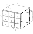
- FIG. 9 is a perspective view showing the front side maintenance space 14 shown in FIG. 1 formed between the heat exchanger 12 and the row of racks 2.
- FIG. 10 is an enlarged perspective view showing only the heat exchanger 12.
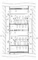
- the flat plate heat exchanger 12 shown in FIGS. 9 and 10 includes a plurality of heat exchanger modules 30 and a plurality of frames 32. A plurality of heat exchanger modules 30 are attached to one frame 32, and a plurality of frames 32 are connected to form a flat plate heat exchanger 12 in which the heat exchanger modules 30 are arranged in a matrix. Is done.
- Cooling water is supplied as a refrigerant to each of the heat exchanger modules 30, and each of the heat exchanger modules 30 can individually cool the air passing through the heat exchanger module 30.
- the heat exchanger 12 may be formed by one large heat exchanger module, the temperature of the cooling water changes between the supply side and the discharge side of the cooling water, and the entire heat exchanger 12 is uniformly cooled. May not be possible. Therefore, in the heat exchanger 12 shown in FIGS. 9 and 10, a plurality of small heat exchanger modules 30 are connected to form a single heat exchanger 12, and each heat exchanger module 30 is individually provided. Cooling water is supplied to
- FIG. 11 is a side view showing a state in which piping for supplying cooling water to the heat exchanger 12 is connected.
- a gantry 34 is installed on the slab 8 under the floor of the computer room, and a frame 32 to which a plurality of heat exchanger modules 30 are attached is fixed on the gantry 34.
- a cooling water supply side pipe 36 and a return side pipe 38 are provided on the slab 8 under the floor.
- a supply side manifold 36A is provided in the middle of the supply side pipe 36.
- a return side manifold 38A is provided in the middle of the return side pipe 38.
- a cooling water supply pipe 40 extending from one supply side manifold 36A is connected to each of the heat exchanger modules 30 attached to one frame 32, and cooling extending from one return side manifold 38A is connected.
- a water return pipe 42 is connected. Therefore, the low-temperature cooling water flowing through the supply side pipe 36 flows from the supply side manifold 36 ⁇ / b> A through the cooling water supply pipe 40 and is supplied to one heat exchanger module 30. While the low-temperature cooling water flows through the heat exchanger module 30, the passing air is cooled to become high-temperature cooling water. The high-temperature cooling water is discharged to the cooling water return pipe 42 and flows to the return side pipe 38 via the return side manifold 38A.
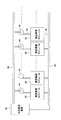
- FIG. 13 shows the cooling water circulation circuit shown in FIG.
- the supply side pipe 36 and the return side pipe 38 are connected to a cold water production apparatus 46.
- the cold water production apparatus 46 includes a pump and a heat exchanger, cools the high-temperature cooling water flowing from the return side pipe 38 into low-temperature cooling water, and sends it to the supply side pipe 36.
- Each of the cooling water pumps 44 pumps low-temperature cooling water from the supply side pipe 36 and supplies it to the heat exchanger module 30.
- the low-temperature cooling water cools the air to become high-temperature cooling water, and is discharged to the return side pipe 38.
- an air temperature sensor 50 may be provided in each of the heat exchanger modules 30, and the flow rate of the cooling water supplied may be controlled based on the temperature of the air passing through the heat exchanger module 30.
- the air temperature sensor 50 is provided on the intake side of the heat exchanger module 30 and detects the temperature of hot air entering the heat exchanger module 30.
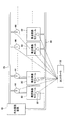
- FIG. 15 is a circuit diagram of a cooling water circulation system capable of controlling the cooling water flow rate to each heat exchanger module 30. 15, parts that are the same as the parts shown in FIG. 13 are given the same reference numerals, and descriptions thereof will be omitted.
- the temperature detection value from the air temperature sensor 50 provided in each of the heat exchanger modules 30 is sent to the controller 52.
- the temperature detection value from the air temperature sensor 50 is the temperature value of the high-temperature air entering each heat exchanger module 30.
- the controller 52 controls each cooling water pump 44 based on the temperature detection value from the air temperature sensor 50 to adjust the flow rate of the cooling water.
- the controller 52 supplies the cooling water for supplying the cooling water to the heat exchanger module 30.
- the flow rate of the pump 44 is increased.
- action of the said heat exchanger module 30 becomes large, and the temperature of the air which passed the said heat exchanger module 30 can be made the same as the temperature of the air which passed the other heat exchanger module 30. .
- FIG. 16 is a schematic diagram showing an air conditioning system having the heat exchanger 12 formed by the heat exchanger module 30 provided with the fan 30a.
- the fan 30a may have an output capable of recovering the small pressure loss of the heat exchanger module 30, and a low-power consumption fan with a low rotation speed is sufficient. Further, since the effect of stirring and mixing the low-temperature air is produced, the fan 30a of each heat exchanger module 30 is substituted for the air stirring fan 24 shown in FIG.
Landscapes
- Engineering & Computer Science (AREA)
- General Engineering & Computer Science (AREA)
- Computer Hardware Design (AREA)
- Physics & Mathematics (AREA)
- Thermal Sciences (AREA)
- Microelectronics & Electronic Packaging (AREA)
- Chemical & Material Sciences (AREA)
- Combustion & Propulsion (AREA)
- Mechanical Engineering (AREA)
- Cooling Or The Like Of Electrical Apparatus (AREA)
Abstract
Selon l'invention, un râtelier (2) recevant un instrument électronique (4) aspire de l'air à partir d'un côté de surface avant, et décharge de l'air à partir d'un côté de surface arrière. Un échangeur de chaleur (12) est disposé en face de la surface avant (2a) du râtelier (2). Un espace clos prédéterminé (14) est formé entre l'échangeur de chaleur (12) et la surface avant (2a) du râtelier (2). Il est formé un canal d'écoulement d'air (10), dans lequel de l'air déchargé sur le côté de surface arrière du râtelier s'écoule vers le côté d'admission de l'échangeur de chaleur sans traverser l'espace clos prédéterminé (14).
Priority Applications (1)
| Application Number | Priority Date | Filing Date | Title |
|---|---|---|---|
| PCT/JP2011/069768 WO2013030979A1 (fr) | 2011-08-31 | 2011-08-31 | Système de climatisation et échangeur de chaleur |
Applications Claiming Priority (1)
| Application Number | Priority Date | Filing Date | Title |
|---|---|---|---|
| PCT/JP2011/069768 WO2013030979A1 (fr) | 2011-08-31 | 2011-08-31 | Système de climatisation et échangeur de chaleur |
Publications (1)
| Publication Number | Publication Date |
|---|---|
| WO2013030979A1 true WO2013030979A1 (fr) | 2013-03-07 |
Family
ID=47755529
Family Applications (1)
| Application Number | Title | Priority Date | Filing Date |
|---|---|---|---|
| PCT/JP2011/069768 Ceased WO2013030979A1 (fr) | 2011-08-31 | 2011-08-31 | Système de climatisation et échangeur de chaleur |
Country Status (1)
| Country | Link |
|---|---|
| WO (1) | WO2013030979A1 (fr) |
Cited By (2)
| Publication number | Priority date | Publication date | Assignee | Title |
|---|---|---|---|---|
| WO2015024704A1 (fr) * | 2013-08-20 | 2015-02-26 | Weiss Klimatechnik Gmbh | Système de climatisation d'un espace |
| CN108917109A (zh) * | 2017-04-25 | 2018-11-30 | 维谛技术有限公司 | 一种机房制冷系统、空调风量调节控制方法和装置 |
Citations (7)
| Publication number | Priority date | Publication date | Assignee | Title |
|---|---|---|---|---|
| JP2005228216A (ja) * | 2004-02-16 | 2005-08-25 | Hitachi Ltd | 電子機器 |
| JP2009079890A (ja) * | 2008-10-02 | 2009-04-16 | Softbank Idc Corp | 空調システム |
| JP2009157681A (ja) * | 2007-12-27 | 2009-07-16 | Sanyo Electric Co Ltd | 電子機器冷却装置 |
| JP2010032174A (ja) * | 2008-07-31 | 2010-02-12 | Hitachi Ltd | 冷却システム及び電子装置 |
| JP2010041007A (ja) * | 2008-08-08 | 2010-02-18 | Hitachi Information & Communication Engineering Ltd | 冷却ユニット、電子装置ラック、冷却システム及びその構築方法 |
| JP2011081528A (ja) * | 2009-10-06 | 2011-04-21 | Takasago Thermal Eng Co Ltd | 空調システム |
| JP2011086134A (ja) * | 2009-10-16 | 2011-04-28 | Takasago Thermal Eng Co Ltd | 電子通信機器室等の空調システム |
-
2011
- 2011-08-31 WO PCT/JP2011/069768 patent/WO2013030979A1/fr not_active Ceased
Patent Citations (7)
| Publication number | Priority date | Publication date | Assignee | Title |
|---|---|---|---|---|
| JP2005228216A (ja) * | 2004-02-16 | 2005-08-25 | Hitachi Ltd | 電子機器 |
| JP2009157681A (ja) * | 2007-12-27 | 2009-07-16 | Sanyo Electric Co Ltd | 電子機器冷却装置 |
| JP2010032174A (ja) * | 2008-07-31 | 2010-02-12 | Hitachi Ltd | 冷却システム及び電子装置 |
| JP2010041007A (ja) * | 2008-08-08 | 2010-02-18 | Hitachi Information & Communication Engineering Ltd | 冷却ユニット、電子装置ラック、冷却システム及びその構築方法 |
| JP2009079890A (ja) * | 2008-10-02 | 2009-04-16 | Softbank Idc Corp | 空調システム |
| JP2011081528A (ja) * | 2009-10-06 | 2011-04-21 | Takasago Thermal Eng Co Ltd | 空調システム |
| JP2011086134A (ja) * | 2009-10-16 | 2011-04-28 | Takasago Thermal Eng Co Ltd | 電子通信機器室等の空調システム |
Cited By (2)
| Publication number | Priority date | Publication date | Assignee | Title |
|---|---|---|---|---|
| WO2015024704A1 (fr) * | 2013-08-20 | 2015-02-26 | Weiss Klimatechnik Gmbh | Système de climatisation d'un espace |
| CN108917109A (zh) * | 2017-04-25 | 2018-11-30 | 维谛技术有限公司 | 一种机房制冷系统、空调风量调节控制方法和装置 |
Similar Documents
| Publication | Publication Date | Title |
|---|---|---|
| JP6018257B2 (ja) | サーバファーム冷却システムのための冷気列封入 | |
| JP6285058B2 (ja) | サーバファーム冷却システムのための冷気列封入 | |
| JP5628292B2 (ja) | サーバファーム冷却システムのための冷気列封入 | |
| US6628520B2 (en) | Method, apparatus, and system for cooling electronic components | |
| JP5296457B2 (ja) | 空調システム | |
| JP5605982B2 (ja) | 換気装置および空調換気システム | |
| JP5243094B2 (ja) | ラック空調システム | |
| US20100147490A1 (en) | Apparatus and method for providing in situ cooling of computer data centers during service calls | |
| JP4503083B2 (ja) | 空調機及びその運転方法 | |
| JP5855895B2 (ja) | 通信・情報処理機器室等の空調システム | |
| US20130269385A1 (en) | Air conditioning system for utilizing outside air and air conditioning device thereof | |
| JP5921931B2 (ja) | 空調システム | |
| US20120100795A1 (en) | Air-conditioning system | |
| JP2011133129A (ja) | データセンターにおける局部循環空調システム | |
| JP4931965B2 (ja) | 情報通信機械室における空調機制御方法 | |
| JP2018066503A (ja) | データセンター | |
| JP2009264599A (ja) | ラック空調システム及びその運転方法、ラック型空調機 | |
| WO2013030979A1 (fr) | Système de climatisation et échangeur de chaleur | |
| CN114126334B (zh) | 用于it集群的空气侧节能系统设计 | |
| CN114144018A (zh) | 用于管理数据中心中的气流的系统和方法 |
Legal Events
| Date | Code | Title | Description |
|---|---|---|---|
| 121 | Ep: the epo has been informed by wipo that ep was designated in this application |
Ref document number: 11871556 Country of ref document: EP Kind code of ref document: A1 |
|
| NENP | Non-entry into the national phase |
Ref country code: DE |
|
| 122 | Ep: pct application non-entry in european phase |
Ref document number: 11871556 Country of ref document: EP Kind code of ref document: A1 |
|
| NENP | Non-entry into the national phase |
Ref country code: JP |