WO2013032202A2 - Procédé et équipement utilisateur pour recevoir des signaux de liaison descendante, et procédé et station de base pour transmettre des signaux de liaison descendante - Google Patents
Procédé et équipement utilisateur pour recevoir des signaux de liaison descendante, et procédé et station de base pour transmettre des signaux de liaison descendante Download PDFInfo
- Publication number
- WO2013032202A2 WO2013032202A2 PCT/KR2012/006834 KR2012006834W WO2013032202A2 WO 2013032202 A2 WO2013032202 A2 WO 2013032202A2 KR 2012006834 W KR2012006834 W KR 2012006834W WO 2013032202 A2 WO2013032202 A2 WO 2013032202A2
- Authority
- WO
- WIPO (PCT)
- Prior art keywords
- resource
- grant
- downlink
- unit
- signal
- Prior art date
- Legal status (The legal status is an assumption and is not a legal conclusion. Google has not performed a legal analysis and makes no representation as to the accuracy of the status listed.)
- Ceased
Links
Images






Classifications
-
- H—ELECTRICITY
- H04—ELECTRIC COMMUNICATION TECHNIQUE
- H04L—TRANSMISSION OF DIGITAL INFORMATION, e.g. TELEGRAPHIC COMMUNICATION
- H04L27/00—Modulated-carrier systems
- H04L27/26—Systems using multi-frequency codes
- H04L27/2601—Multicarrier modulation systems
- H04L27/2602—Signal structure
-
- H—ELECTRICITY
- H04—ELECTRIC COMMUNICATION TECHNIQUE
- H04L—TRANSMISSION OF DIGITAL INFORMATION, e.g. TELEGRAPHIC COMMUNICATION
- H04L5/00—Arrangements affording multiple use of the transmission path
- H04L5/003—Arrangements for allocating sub-channels of the transmission path
- H04L5/0037—Inter-user or inter-terminal allocation
-
- H—ELECTRICITY
- H04—ELECTRIC COMMUNICATION TECHNIQUE
- H04L—TRANSMISSION OF DIGITAL INFORMATION, e.g. TELEGRAPHIC COMMUNICATION
- H04L5/00—Arrangements affording multiple use of the transmission path
- H04L5/003—Arrangements for allocating sub-channels of the transmission path
- H04L5/0053—Allocation of signalling, i.e. of overhead other than pilot signals
-
- H—ELECTRICITY
- H04—ELECTRIC COMMUNICATION TECHNIQUE
- H04L—TRANSMISSION OF DIGITAL INFORMATION, e.g. TELEGRAPHIC COMMUNICATION
- H04L5/00—Arrangements affording multiple use of the transmission path
- H04L5/0091—Signalling for the administration of the divided path, e.g. signalling of configuration information
- H04L5/0094—Indication of how sub-channels of the path are allocated
-
- H—ELECTRICITY
- H04—ELECTRIC COMMUNICATION TECHNIQUE
- H04W—WIRELESS COMMUNICATION NETWORKS
- H04W72/00—Local resource management
- H04W72/20—Control channels or signalling for resource management
- H04W72/23—Control channels or signalling for resource management in the downlink direction of a wireless link, i.e. towards a terminal
-
- H—ELECTRICITY
- H04—ELECTRIC COMMUNICATION TECHNIQUE
- H04L—TRANSMISSION OF DIGITAL INFORMATION, e.g. TELEGRAPHIC COMMUNICATION
- H04L27/00—Modulated-carrier systems
- H04L27/26—Systems using multi-frequency codes
- H04L27/2601—Multicarrier modulation systems
- H04L27/2647—Arrangements specific to the receiver only
Definitions
- the present invention relates to a wireless communication system, and more particularly, to a method and apparatus for transmitting / receiving a downlink signal.
- a node is a fixed point capable of transmitting / receiving a radio signal with a user device having one or more antennas.
- a communication system having a high density of nodes can provide higher performance communication services to user equipment by cooperation between nodes.
- the present invention provides a method and apparatus for efficiently transmitting / receiving a downlink signal.
- a base station receives a downlink signal from a user equipment in a wireless communication system, the downlink grant for the user equipment on the first resource unit of a plurality of resource units in a predetermined resource area from the base station (Hereinafter, referred to as a first downlink grant);
- a first downlink grant When resource allocation information in the first downlink grant has a first value, when an uplink grant is detected on a second resource unit among the plurality of resource units, and when the resource allocation information has a second value, A downlink signal receiving method for detecting downlink data on a resource unit is provided.
- a base station receives a downlink signal from a user equipment, the radio frequency (RF) unit configured to transmit / receive a signal; And a processor configured to control the RF unit, wherein the processor includes a downlink grant (hereinafter, referred to as a first downlink grant) for the user equipment on a first resource unit of a plurality of resource units in a predetermined resource region from the base station; Control the RF unit to receive;
- a downlink grant hereinafter, referred to as a first downlink grant
- the processor includes a downlink grant (hereinafter, referred to as a first downlink grant) for the user equipment on a first resource unit of a plurality of resource units in a predetermined resource region from the base station; Control the RF unit to receive;
- resource allocation information in the first downlink grant has a first value
- an uplink grant is detected on a second resource unit among the plurality of resource units, and when the resource allocation information has a second value
- a user equipment is provided, configured to
- a downlink grant for the user equipment on a first resource unit of a plurality of resource units in a predetermined resource area And transmit a first downlink grant) to the user equipment, and transmit uplink grant or downlink data to the user equipment on a second resource unit of the plurality of resource units, and on the second resource unit.
- the first downlink grant includes resource allocation information having a first value
- the first downlink grant is second
- a downlink signal transmission method including resource allocation information having a value is provided.
- a base station receives a downlink signal from a user equipment, the radio frequency (RF) unit being configured to transmit / receive a signal; And a processor configured to control the RF unit, wherein the processor is configured to perform a downlink grant (hereinafter, referred to as a first downlink grant) for the user equipment on a first resource unit among a plurality of resource units in a predetermined resource region.
- a downlink grant hereinafter, referred to as a first downlink grant
- the RF unit Control the RF unit to transmit to the user equipment, control the RF unit to transmit uplink grant or downlink data to the user equipment on a second resource unit of the plurality of resource units, and the second resource unit
- the uplink grant is transmitted on the first downlink grant
- the first downlink grant includes resource allocation information having a first value
- the first downlink grant Is provided which includes resource allocation information having a second value.
- additional information indicating whether a downlink grant (hereinafter referred to as a second downlink grant) for another user equipment may be transmitted from the base station to the user equipment.
- the additional information indicating the presence or absence of a downlink grant (hereinafter, referred to as a second downlink grant) for another user equipment indicates that the second downlink grant does not exist
- the downlink data may be transmitted / received on a third resource unit among resource units.
- the third The downlink data may not be transmitted / received on a resource unit.
- the efficiency of downlink resource usage is increased.
- FIG. 1 illustrates an example of a radio frame structure used in a wireless communication system.
- FIG. 2 illustrates an example of a downlink / uplink (DL / UL) slot structure in a wireless communication system.
- FIG 3 illustrates a downlink (DL) subframe structure used in a 3GPP LTE / LTE-A system.
- FIG. 4 illustrates an example of an uplink (UL) subframe structure used in a 3GPP LTE / LTE-A system.
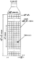
- FIG. 5 illustrates a method of mapping a virtual resource block to a physical resource block.
- Type 6 RA Resource Allocation
- Type 2 RA resource allocation examples
- FIG 9 and 10 illustrate examples of resource allocation according to an embodiment of the present invention.
- 11 to 13 illustrate examples of resource allocation according to another embodiment of the present invention.
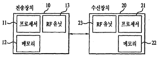
- 16 is a block diagram showing the components of the transmitter 10 and the receiver 20 for carrying out the present invention.
- 17 illustrates an example of a signal processing process in the transmitter 10.
- a user equipment may be fixed or mobile, and various devices which transmit and receive user data and / or various control information by communicating with a base station (BS) belong to this.
- the UE may be a terminal equipment (MS), a mobile station (MS), a mobile terminal (MT), a user terminal (UT), a subscriber station (SS), a wireless device, a personal digital assistant (PDA), or a wireless modem. It may be called a modem, a handheld device, or the like.
- a BS generally refers to a fixed station communicating with the UE and / or another BS, and communicates with the UE and another BS to exchange various data and control information.
- the BS may be referred to in other terms such as ABS (Advanced Base Station), NB (Node-B), eNB (evolved-NodeB), BTS (Base Transceiver System), Access Point (Access Point), and Processing Server (PS).
- ABS Advanced Base Station
- NB Node-B
- eNB evolved-NodeB
- BTS Base Transceiver System
- Access Point Access Point
- PS Processing Server
- BS is collectively referred to as eNB.
- a node refers to a fixed point capable of transmitting / receiving a radio signal by communicating with a user equipment.
- Various forms of eNBs may be used as nodes regardless of their name.
- the node may be a BS, an NB, an eNB, a pico-cell eNB (PeNB), a home eNB (HeNB), a relay, a repeater, and the like.
- the node may not be an eNB.
- it may be a radio remote head (RRH), a radio remote unit (RRU).
- RRHs, RRUs, etc. generally have a power level lower than the power level of the eNB.
- RRH or RRU, RRH / RRU is generally connected to an eNB by a dedicated line such as an optical cable
- RRH / RRU and eNB are generally compared to cooperative communication by eNBs connected by a wireless line.
- cooperative communication can be performed smoothly.
- At least one antenna is installed at one node.
- the antenna may mean a physical antenna or may mean an antenna port, a virtual antenna, or an antenna group.
- Nodes are also called points. Unlike conventional centralized antenna systems (ie, single node systems) where antennas are centrally located at base stations and controlled by one eNB controller, in a multi-node system A plurality of nodes are typically located farther apart than a predetermined interval.
- the plurality of nodes may be managed by one or more eNBs or eNB controllers that control the operation of each node or schedule data to be transmitted / received through each node.
- Each node may be connected to the eNB or eNB controller that manages the node through a cable or dedicated line.
- the same cell identifier (ID) may be used or different cell IDs may be used for signal transmission / reception to / from a plurality of nodes.
- ID cell identifier
- each of the plurality of nodes behaves like some antenna group of one cell.
- a multi-node system may be regarded as a multi-cell (eg, macro-cell / femto-cell / pico-cell) system.
- the network formed by the multiple cells is particularly called a multi-tier network.
- the cell ID of the RRH / RRU and the cell ID of the eNB may be the same or may be different.
- both the RRH / RRU and the eNB operate as independent base stations.
- a cell refers to a certain geographic area in which one or more nodes provide a communication service. Therefore, in the present invention, communication with a specific cell may mean communication with an eNB or a node that provides a communication service to the specific cell.
- the downlink / uplink signal of a specific cell means a downlink / uplink signal from / to an eNB or a node that provides a communication service to the specific cell.
- the channel state / quality of a specific cell means a channel state / quality of a channel or communication link formed between an eNB or a node providing a communication service to the specific cell and a UE.
- a UE transmits a downlink channel state from a specific node on a channel CSI-RS (Channel State Information Reference Signal) resource to which the antenna port (s) of the specific node is assigned to the specific node. Can be measured using CSI-RS (s).
- CSI-RS Channel State Information Reference Signal
- adjacent nodes transmit corresponding CSI-RS resources on CSI-RS resources orthogonal to each other. Orthogonality of CSI-RS resources means that the CSI-RS is allocated by CSI-RS resource configuration, subframe offset, and transmission period that specify symbols and subcarriers carrying the CSI-RS. This means that at least one of a subframe configuration and a CSI-RS sequence for specifying the specified subframes are different from each other.
- Physical Downlink Control CHannel / Physical Control Format Indicator CHannel (PCFICH) / PHICH (Physical Hybrid automatic retransmit request Indicator CHannel) / PDSCH (Physical Downlink Shared CHannel) are respectively DCI (Downlink Control Information) / CFI ( Means a set of time-frequency resources or a set of resource elements that carry downlink format ACK / ACK / NACK (ACKnowlegement / Negative ACK) / downlink data, and also a physical uplink control channel (PUCCH) / physical (PUSCH).
- DCI Downlink Control Information
- CFI Means a set of time-frequency resources or a set of resource elements that carry downlink format ACK / ACK / NACK (ACKnowlegement / Negative ACK) / downlink data, and also a physical uplink control channel (PUCCH) / physical (PUSCH).
- Uplink Shared CHannel / PACH Physical Random Access CHannel refers to a set of time-frequency resources or a set of resource elements that carry uplink control information (UCI) / uplink data / random access signals, respectively.
- Resource elements (REs) are referred to as PDCCH / PCFICH / PHICH / PDSCH / PUCCH / PUSCH / PRACH RE or PDCCH / PCFICH / PHICH / PDSCH / PUCCH / PUSCH / PRACH resources, respectively.
- the expression that the user equipment transmits PUCCH / PUSCH / PRACH is used as the same meaning as transmitting uplink control information / uplink data / random access signal on or through the PUSCH / PUCCH / PRACH, respectively.
- the expression that the eNB transmits PDCCH / PCFICH / PHICH / PDSCH is used in the same sense as transmitting downlink data / control information on or through the PDCCH / PCFICH / PHICH / PDSCH, respectively.
- the time resource means a radio resource defined in the time domain
- the frequency resource means a radio resource defined in the frequency domain
- the spatial resource means a radio resource defined in the spatial domain.
- Temporal resources can be identified by OFDM / SC-FDM symbol, slot, subframe, or frame
- frequency resources can be identified by subcarrier, RB, RBG, carrier, and spatial resources by layer or antenna port. Can be distinguished.
- Figure 1 illustrates an example of a radio frame structure used in a wireless communication system.
- Figure 1 (a) shows a frame structure for frequency division duplex (FDD) used in the 3GPP LTE / LTE-A system
- Figure 1 (b) is used in the 3GPP LTE / LTE-A system
- the frame structure for time division duplex (TDD) is shown.
- a radio frame used in a 3GPP LTE / LTE-A system has a length of 10 ms (307200 T s ) and consists of 10 equally sized subframes (subframes). Numbers may be assigned to 10 subframes in one radio frame.
- Each subframe has a length of 1 ms and consists of two slots. 20 slots in one radio frame may be sequentially numbered from 0 to 19. Each slot is 0.5ms long.
- the time for transmitting one subframe is defined as a transmission time interval (TTI).
- the time resource may be classified by a radio frame number (also called a radio frame index), a subframe number (also called a subframe number), a slot number (or slot index), and the like.
- the radio frame may be configured differently according to the duplex mode. For example, in the FDD mode, since downlink transmission and uplink transmission are divided by frequency, a radio frame includes only one of a downlink subframe or an uplink subframe for a specific frequency band. In the TDD mode, since downlink transmission and uplink transmission are separated by time, a radio frame includes both a downlink subframe and an uplink subframe for a specific frequency band.
- Table 1 illustrates a DL-UL configuration of subframes in a radio frame in the TDD mode.
- D represents a downlink subframe
- U represents an uplink subframe
- S represents a special subframe.
- the singular subframe includes three fields of Downlink Pilot TimeSlot (DwPTS), Guard Period (GP), and Uplink Pilot TimeSlot (UpPTS).
- DwPTS is a time interval reserved for downlink transmission
- UpPTS is a time interval reserved for uplink transmission.
- Table 2 illustrates the configuration of a singular frame.
- FIG. 2 illustrates an example of a downlink / uplink (DL / UL) slot structure in a wireless communication system.
- FIG. 2 shows a structure of a resource grid of a 3GPP LTE / LTE-A system. There is one resource grid per antenna port.
- a slot includes a plurality of Orthogonal Frequency Division Multiplexing (OFDM) symbols in a time domain and a plurality of resource blocks (RBs) in a frequency domain.
- An OFDM symbol may mean a symbol period.
- a signal transmitted in each slot may be represented by a resource grid including N DL / UL RB * N RB sc subcarriers and N DL / UL symb OFDM symbols.
- N DL RB represents the number of resource blocks (RBs) in the downlink slot
- N UL RB represents the number of RBs in the UL slot.
- N DL RB and N UL RB depend on DL transmission bandwidth and UL transmission bandwidth, respectively.
- N DL symb represents the number of OFDM symbols in the downlink slot
- N UL symb represents the number of OFDM symbols in the UL slot.
- N RB sc represents the number of subcarriers constituting one RB.
- the OFDM symbol may be called an OFDM symbol, a Single Carrier Frequency Division Multiplexing (SC-FDM) symbol, or the like according to a multiple access scheme.
- the number of OFDM symbols included in one slot may vary depending on the channel bandwidth and the length of the cyclic prefix (CP). For example, in case of a normal CP, one slot includes 7 OFDM symbols, whereas in case of an extended CP, one slot includes 6 OFDM symbols.
- FIG. 2 illustrates a subframe in which one slot includes 7 OFDM symbols for convenience of description, embodiments of the present invention can be applied to subframes having other numbers of OFDM symbols in the same manner. Referring to FIG.
- each OFDM symbol includes N DL / UL RB * N RB sc subcarriers in the frequency domain.
- the types of subcarriers may be divided into data subcarriers for data transmission, reference signal subcarriers for transmission of reference signals, null subcarriers for guard band, and direct current (DC) components.
- the null subcarrier for the DC component is a subcarrier left unused and is mapped to a carrier frequency f 0 during an OFDM signal generation process or a frequency upconversion process.
- the carrier frequency is also called the center frequency.
- One RB is defined as N DL / UL symb (e.g., seven) consecutive OFDM symbols in the time domain and is defined by N RB sc (e.g., twelve) consecutive subcarriers in the frequency domain. Is defined.
- N DL / UL symb e.g., seven
- N RB sc e.g., twelve
- a resource composed of one OFDM symbol and one subcarrier is called a resource element (RE) or tone. Therefore, one RB is composed of N DL / UL symb * N RB sc resource elements.
- Each resource element in the resource grid may be uniquely defined by an index pair (k, 1) in one slot.
- k is an index given from 0 to N DL / UL RB * N RB sc ⁇ 1 in the frequency domain
- l is an index given from 0 to N DL / UL symb ⁇ 1 in the time domain.
- Two RBs each occupying N RB sc consecutive subcarriers in one subframe and one located in each of two slots of the subframe, are called a physical resource block (PRB) pair.
- Two RBs constituting a PRB pair have the same PRB number (or also referred to as a PRB index).
- FIG 3 illustrates a downlink (DL) subframe structure used in a 3GPP LTE / LTE-A system.
- a DL subframe is divided into a control region and a data region in the time domain.
- up to three (or four) OFDM symbols located in the first slot of a subframe correspond to a control region to which a control channel is allocated.
- a resource region available for PDCCH transmission in a DL subframe is called a PDCCH region.
- the remaining OFDM symbols other than the OFDM symbol (s) used as the control region correspond to a data region to which a Physical Downlink Shared CHannel (PDSCH) is allocated.
- PDSCH Physical Downlink Shared CHannel
- a resource region available for PDSCH transmission in a DL subframe is called a PDSCH region.
- Examples of DL control channels used in 3GPP LTE include a physical control format indicator channel (PCFICH), a physical downlink control channel (PDCCH), a physical hybrid ARQ indicator channel (PHICH), and the like.
- the PCFICH is transmitted in the first OFDM symbol of a subframe and carries information about the number of OFDM symbols used for transmission of a control channel within the subframe.
- the PHICH carries a Hybrid Automatic Repeat Request (HARQ) ACK / NACK (acknowledgment / negative-acknowledgment) signal in response to the UL transmission.
- HARQ Hybrid Automatic Repeat Request
- DCI downlink control information
- DL-SCH downlink shared channel
- UL-SCH uplink shared channel
- paging channel a downlink shared channel
- the transmission format and resource allocation information of a downlink shared channel may also be called DL scheduling information or a DL grant, and may be referred to as an uplink shared channel (UL-SCH).
- the transmission format and resource allocation information is also called UL scheduling information or UL grant.
- the DCI carried by one PDCCH has a different size and use depending on the DCI format, and its size may vary depending on a coding rate.
- various formats such as formats 0 and 4 for uplink and formats 1, 1A, 1B, 1C, 1D, 2, 2A, 2B, 2C, 3, and 3A are defined for uplink.
- Hopping flag RB allocation, modulation coding scheme (MCS), redundancy version (RV), new data indicator (NDI), transmit power control (TPC), and cyclic shift DMRS Control information such as shift demodulation reference signal (UL), UL index, CQI request, DL assignment index, HARQ process number, transmitted precoding matrix indicator (TPMI), and precoding matrix indicator (PMI) information
- MCS modulation coding scheme
- RV redundancy version
- NDI new data indicator
- TPC transmit power control
- cyclic shift DMRS Control information such as shift demodulation reference signal (UL), UL index, CQI request, DL assignment index, HARQ process number, transmitted precoding matrix indicator (TPMI), and precoding matrix indicator (PMI) information
- UL shift demodulation reference signal
- CQI request UL assignment index
- HARQ process number transmitted precoding matrix indicator
- PMI precoding matrix indicator
- the PDCCH is transmitted on an aggregation of one or a plurality of consecutive control channel elements (CCEs).
- CCE is a logical allocation unit used to provide a PDCCH with a coding rate based on radio channel conditions.
- the CCE corresponds to a plurality of resource element groups (REGs). For example, one CCE corresponds to nine REGs and one REG corresponds to four REs.
- REGs resource element groups
- a CCE set in which a PDCCH can be located is defined for each UE.
- the set of CCEs in which a UE can discover its PDCCH is referred to as a PDCCH search space, simply a search space (SS).
- SS search space
- PDCCH candidate An individual resource to which a PDCCH can be transmitted in a search space is called a PDCCH candidate.
- the collection of PDCCH candidates that the UE will monitor is defined as a search space.
- a search space for each DCI format may have a different size, and a dedicated search space and a common search space are defined.
- the dedicated search space is a UE-specific search space and is configured for each individual UE.
- the common search space is configured for a plurality of UEs. Table 3 illustrates the aggregation levels that define the search spaces.
- One PDCCH candidate corresponds to 1, 2, 4, or 8 CCEs according to a CCE aggregation level.
- the eNB sends the actual PDCCH (DCI) on any PDCCH candidate in the search space, and the UE monitors the search space to find the PDCCH (DCI).
- monitoring means attempting decoding of each PDCCH in a corresponding search space according to all monitored DCI formats.
- the UE may detect its own PDCCH by monitoring the plurality of PDCCHs. Basically, since the UE does not know where its PDCCH is transmitted, every Pframe attempts to decode the PDCCH until every PDCCH of the corresponding DCI format has detected a PDCCH having its own identifier. It is called blind detection (blind decoding).
- the eNB may transmit data for the UE or the UE group through the data area.
- Data transmitted through the data area is also called user data.
- a physical downlink shared channel (PDSCH) may be allocated to the data area.
- Paging channel (PCH) and downlink-shared channel (DL-SCH) are transmitted through PDSCH.
- the UE may read data transmitted through the PDSCH by decoding control information transmitted through the PDCCH.
- Information indicating to which UE or UE group data of the PDSCH is transmitted, how the UE or UE group should receive and decode PDSCH data, and the like are included in the PDCCH and transmitted.
- a specific PDCCH is masked with a cyclic redundancy check (CRC) with a Radio Network Temporary Identity (RNTI) of "A", a radio resource (eg, a frequency location) of "B” and a transmission of "C".
- CRC cyclic redundancy check
- RNTI Radio Network Temporary Identity
- format information eg, transport block size, modulation scheme, coding information, etc.
- FIG. 4 illustrates an example of an uplink (UL) subframe structure used in a 3GPP LTE / LTE-A system.
- the UL subframe may be divided into a control region and a data region in the frequency domain.
- One or several physical uplink control channels may be allocated to the control region to carry uplink control information (UCI).
- One or several physical uplink shared channels may be allocated to a data region of a UL subframe to carry user data.
- the PUSCH may be transmitted together with a DeModulation Reference Signal (DMRS), which is a reference signal (RS) for demodulation of user data transmitted through the PUSCH.
- DMRS DeModulation Reference Signal
- the control region and data region in the UL subframe may also be called a PUCCH region and a PUSCH region, respectively.
- a sounding reference signal may be allocated to the data area.
- the SRS is transmitted in the OFDM symbol located at the end of the UL subframe in the time domain and in the data transmission band of the UL subframe, that is, in the data domain, in the frequency domain.
- SRSs of several UEs transmitted / received in the last OFDM symbol of the same subframe may be distinguished according to frequency location / sequence.
- SC-FDMA Single Carrier Frequency Division Multiplexing Access
- PUCCH and PUSCH are performed on one carrier. Can't send at the same time.
- whether to support simultaneous transmission of a PUCCH and a PUSCH may be indicated in a higher layer.
- subcarriers having a long distance based on a direct current (DC) subcarrier are used as a control region.
- subcarriers located at both ends of the UL transmission bandwidth are allocated for transmission of uplink control information.
- the DC subcarrier is a component that is not used for signal transmission and is mapped to a carrier frequency f 0 during frequency upconversion.
- the PUCCH for one UE is allocated to an RB pair belonging to resources operating at one carrier frequency in one subframe, and the RBs belonging to the RB pair occupy different subcarriers in two slots.
- the PUCCH allocated in this way is expressed as that the RB pair allocated to the PUCCH is frequency hopped at the slot boundary. However, if frequency hopping is not applied, RB pairs occupy the same subcarrier.
- PUCCH may be used to transmit the following control information.
- SR Service Request: Information used for requesting an uplink UL-SCH resource. It is transmitted using OOK (On-Off Keying) method.
- HARQ-ACK A response to a PDCCH and / or a response to a downlink data packet (eg, codeword) on a PDSCH. This indicates whether the PDCCH or PDSCH is successfully received.
- One bit of HARQ-ACK is transmitted in response to a single downlink codeword, and two bits of HARQ-ACK are transmitted in response to two downlink codewords.
- HARQ-ACK response includes a positive ACK (simple, ACK), negative ACK (hereinafter, NACK), DTX (Discontinuous Transmission) or NACK / DTX.
- NACK negative ACK
- DTX discontinuous Transmission
- HARQ-ACK is mixed with HARQ ACK / NACK, ACK / NACK.
- CSI Channel State Information
- MIMO Multiple Input Multiple Output
- RI rank indicator
- PMI precoding matrix indicator
- PRBs Physical Resource Blocks
- VRBs Virtual Resource Blocks
- the PRB is the same as that illustrated in FIG. That is, PRB is defined as N DL symb contiguous OFDM symbols in the time domain and N RB sc contiguous subcarriers in the frequency domain. PRBs are numbered 0-N DL RB- 1 in the frequency domain.
- the relation between the PRB number n PRB and the resource element ( k, l ) in the slot is as follows.
- VRB is a kind of logical resource allocation unit introduced for resource allocation.
- VRB has the same size as PRB.
- a VRB is divided into a localized VRB (Localized VRB, LVRB) and a distributed type VRB (Distributed VRB, DVRB).
- a pair of resource blocks are allocated together by a single VRB number n VRB across two slots in a subframe.
- Two PRBs, one located in two slots of a subframe and having the same VRB number, are called VRB pairs.
- FIG. 5 illustrates a method of mapping a virtual resource block to a physical resource block.
- DVRBs are mapped to PRBs through interleaving. Therefore, DVRBs having the same VRB number may be mapped to PRBs having different numbers in the first slot and the second slot. Specifically, the DVRB may be mapped to the PRB as shown in Table 4. Table 4 illustrates the RB gap values.
- N gap represents the frequency interval (eg, PRB unit) when VRBs of the same number are mapped to PRBs of the first slot and the second slot.
- N gap N gap, 1
- two gap values N gap, 1 and N gap, 2 are defined.
- min (A, B) represents the smaller of A or B, floor is a rounding operation, and floor (x) represents the largest integer not greater than x.
- VRB number interleaving of each interleaving unit may be performed using four columns and N row rows.
- N row ⁇ ceil (N to DL VRB / (4P)) ⁇ ⁇ P, where P represents a resource block group (RBG) size.
- RBG resource block group
- the UE interprets the resource allocation field based on the detected PDCCH DCI format.
- the resource allocation field in each PDCCH includes two parts of a resource allocation header field and actual resource block allocation information.
- PDCCH DCI formats 1, 2, and 2A for type 0 and type 1 resource allocation are distinguished from each other through a single bit resource allocation header field having the same format and existing according to a downlink system band. Specifically, type 0 RA is indicated as 0 and type 1 RA is indicated as 1.
- PDCCH DCI formats 1, 2 and 2A are used for type 0 or type 1 RAs, while PDCCH DCI formats 1A, 1B, 1C and 1D are used for type 2 RAs.
- PDCCH DCI format with Type 2 RA does not have a resource allocation header field.
- the resource allocation field indicates the PRB set of the first slot.
- the PRB set of the second slot is determined by the slot hopping rule.
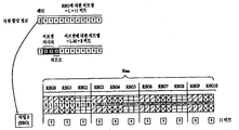
- the resource block allocation information in a type 0 RA includes a bitmap indicating a resource block group (RBG) allocated to the terminal.
- RBG is a set of consecutive PRBs.
- RBG size (P) depends on the system band as shown in Table 5.
- N RBG ceil (N DL RB / P)
- N DL RB / P the floor (N DL RB / P) RBGs have a size P
- N DL RB mod P> 0 one of the RBGs is N DL RB -P ⁇ (floor (N DL RB / P)).
- mod represents a modulo operation.
- the size of the bitmap is N RBG and each bit corresponds to one RBG.
- the total RBG is indexed from 0 to N RBG- 1 in the frequency increasing direction, and RBG 0 to RBG N RBG- 1 is mapped from the most significant bit (MSB) of the bitmap to the least significant bit (LSB).
- resource block assignment information having an N RBG size in a type 1 RA indicates to a scheduled UE resources in a RBG subset in PRB units.
- RBG subset p (0 ⁇ p ⁇ P) consists of every P th RBG starting from RBG p.
- Resource block allocation information is composed of three fields. The first field is ceil ⁇ log 2 (P) ⁇ bits and indicates an RBG subset selected from the P RBG subsets. The second field is 1 bit and indicates the shift of resource allocation span within the subset. If the bit value is 1, a shift is triggered and vice versa.
- the third field contains a bitmap, each bit indicating one PRB in the selected RBG set.
- the bitmap portion used to indicate the PRB in the selected RBG subset is N TYPE1 RB in size and is defined as follows.
- the addressable PRB number in the selected RBG subset may start from the offset ( ⁇ shift (p)) for the smallest PRB number in the selected RBG subset and map to the MSB of the bitmap.
- N RBGsubset RB (p) represents the number of PRBs in RBG subset p and can be obtained according to the following.
- resource block allocation information indicates a set of LVRBs or DVRBs continuously allocated to a scheduled UE.
- a 1-bit flag indicates whether an LVRB or DVRB is allocated (eg, 0 indicates LVRB allocation and 1 indicates DVRB allocation).
- PDCCH DCI format 1C only DVRB is always allocated.
- the type 2 resource allocation field includes a resource indication value (RIV), and the RIV corresponds to a start resource block RB start and a length. The length represents the number of resource blocks allocated virtually consecutively.
- a new remote radio head (RRH) is being discussed.
- a plurality of carriers may be configured in one UE.
- Each of the carrier aggregated carriers is called a component carrier (CC), and a CC configured in the UE is called a serving CC.
- CC component carrier
- serving CC serving CC
- a PDCCH according to the existing 3GPP LTE (-A) standard may be allocated to a PDCCH region of a DL subframe, and a PDCCH may be additionally or separately allocated using some resources of the PDSCH region.
- the conventional PDCCH transmitted in the PDCCH region is transmitted using resources that span a wide frequency band in the frequency domain, whereas the PDCCH transmitted in the PDSCH region is usually transmitted using only a narrow frequency band.
- the PDCCH transmitted in the latter OFDM symbols (PDSCH region) of the DL subframe is embedded PDCCH (e-PDCCH). It is called).
- the e-PDCCH may be referred to as an enhanced PDCCH (E-PDCCH) or an advanced PDCCH (A-PDCCH), and the PDSCH / PUSCH scheduled by the e-PDCCH may also be called an e-PDSCH / e-PUSCH.
- E-PDCCH enhanced PDCCH
- A-PDCCH advanced PDCCH
- PDSCH / PUSCH scheduled by the e-PDCCH may also be called an e-PDSCH / e-PUSCH.
- the R-PDCCH transmits downlink control information.
- the R-PDCCH carries a DCI for RNs.
- R-PDCCH is transmitted / received in PDSCH region unlike normal 3GPP LTE PDCCH, and DL R-PDCCH (i.e., R-PDCCH carrying DL grant) has UL R-PDCCH (i.e. carrying UL grant in the first slot).
- R-PDCCH is transmitted / received in the second slot.
- the R-PDCCH may be regarded as a kind of e-PDCCH in that it is located in the PDSCH region.
- the present invention proposes a structure of the proposed e-PDCCH and a resource allocation method using the same to overcome the limitations of the existing PDCCH.
- the e-PDCCH is largely classified into two categories-a DL grant and a UL grant.
- the DL grant carries information on time / frequency / spatial resources of the PDSCH carrying information that the UE should receive and information for decoding.
- the UL grant carries information on time / frequency / spatial resources of a PUSCH and data for decoding, which carries data that the UE should transmit on the uplink.
- the allocated resource region includes (a) the data for the UE or a UE group including the UE, (b) a UL grant for the UE, (c) There may be a DL grant for another UE and / or (d) an UL grant for another UE.
- the process for signal recovery varies according to the type of signal.
- the present invention proposes an (implicit) resource assignment method for a single layer or multiple layers, which is suitable for an e-PDCCH.
- the time-frequency region indicated by the time axis and the frequency axis corresponds to a downlink resource region allocated to one UE, and may have various sizes.
- resources may be allocated to the UE in units of PRB pairs or RBGs.
- the e-PDCCH DL / UL grant of the present invention may occupy one RB in the allocated pair or RBG, but may be configured to occupy a resource unit smaller than the RB.
- a number of REs corresponding to one-half or one-quarter of the RB may be used, with 12 subcarriers in which the RB is localized or continuous, and X rather than one slot.
- X has a structure defined by subcarriers of positive integers other than 12 and Y OFDM symbols (Y is positive integers other than 6 or 7) or is distributed or non-consecutive ) May have a structure defined by subcarriers and / or distributed / discontinuous OFDM symbols.
- Y is positive integers other than 6 or 7
- Y is distributed or non-consecutive
- a resource unit a unit of a resource occupied by an e-PDCCH carrying a DL / UL grant.
- an RBG consists of one or more consecutive RBs in the frequency domain.
- FIGS. 9 to 15 may be exemplified when the RBG includes three consecutive RBs.
- RB means PRB or VRB.
- 9 to 15 illustrate a case in which a predetermined resource region allocated to a UE or a UE group is divided into six small regions and one UL grant exists within the predetermined resource region, but the predetermined resource allocated to the UE or UE group is illustrated.
- the UL grant and / or the DL grant may be located in the predetermined resource region in a different form from that of FIGS. 9 to 15.
- a DL grant or higher layer signal transmitted through the PDCCH may carry information about a search space for the e-PDCCH of the UE.
- a predetermined downlink resource region eg, RBG
- RBG predetermined downlink resource region
- a specific resource unit eg, a resource in the RBG
- a resource unit with the lowest index of units may be defined as an e-PDCCH search space carrying a DL grant.
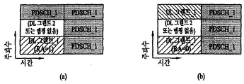
- FIG 9 and 10 illustrate examples of resource allocation according to an embodiment of the present invention.
- one bit (hereinafter, referred to as RA bit) of RA information included in a DL grant is assigned to (1) a PDSCH in a remaining region except for resources occupied by the DL grant among the allocated resource regions, or (2) It is interpreted as a signal indicating that PDSCH has been allocated to a region other than the resource occupied by the DL grant and a resource previously designated to occupy the UL grant.
- the location of the UL grant may be a resource unit (eg, a PRB) adjacent to the DL grant, but may also mean a resource unit of a previously designated location.
- FIG 9 illustrates a case where the present embodiment is applied to downlink signal transmission through a single antenna port (or layer).
- an eNB when an eNB allocates PDSCH (s) to resource units other than resource units occupied by a DL grant among RBG resource units to be allocated to a UE, the eNB May set the RA bit in the DL grant to 1 and transmit the DL grant to the UE through an e-PDCCH.
- the UE receives the DL grant including the RA bit set to 1, it can be seen that PDSCH (s) are allocated to the remaining resource units except the resource unit occupied by the DL grant among the resource units in the allocated RBG. have.
- the UE detects / acquires DCI by performing signal processing for restoring control information with respect to a signal received on a resource unit occupied by a DL grant among signals received on an allocated RBG, and detects / acquires a DCI and occupies the DL grant.
- an eNB when an eNB allocates a UL grant as well as a DL grant and a PDSCH to resource units of an RBG to be allocated to a UE, the eNB sets the RA bit in the DL grant to 0.
- the DL grant may be transmitted to the UE through an e-PDCCH.
- the UE receives the DL grant including the RA bit set to 0, the remaining resources except for the resource unit occupied by the DL grant and the resource unit occupied by a predetermined UL grant among the resource units in the RBG allocated to the UE.
- Units may be interpreted as having been assigned PDSCH (s).
- the UE detects and acquires a DL grant DCI by performing a signal processing procedure for restoring control information on a signal received on a resource unit occupied by a DL grant among signals received on an allocated RBG, and occupies a UL grant.
- Performing a signal processing for restoring control information on a signal received on a predetermined resource unit to detect / acquire a UL grant DCI, and receive the received data on resource units other than the resource unit occupied by the DL grant.
- Downlink data can be detected / acquired by performing a signal processing process for data restoration on the signal.
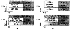
- FIG. 10 illustrates a case where the present embodiment is applied to downlink signal transmission (ie, downlink signal transmission by spatial multiplexing) through a plurality of antenna ports (or layers).
- FIG. 10 illustrates a case where the present embodiment is applied to a single user MIMO (SU-MIMO) in which one UE uses all layers.
- SU-MIMO single user MIMO
- a DL grant of antenna port 0 (hereinafter referred to as port 0) is detected and the RA bit in the DL grant is 1, that is, a DL grant transmitted through port 0 of the eNB is detected.
- the RA bit in the DL grant is 1, it means that the PDSCH is allocated to other resource units except for the corresponding resource unit of port 0 where the DL grant is detected and resource units of the remaining port (eg, port 1).
- the spatial multiplexing technique may not be applied to the transmission of the DL grant. When the spatial multiplexing technique is not applied to the transmission of the DL grant, as shown in FIG.
- the resource unit of the port 1 corresponding to the resource unit of the port 0 where the DL grant is detected (eg, the DL grant is detected).
- PDSCH is not mapped to a resource unit occupying the same time-frequency resource as that of the resource unit of port 0).
- a UL grant is transmitted from a resource unit of a predetermined position among resource regions allocated to the UE, and the DL grant and the UL grant are transmitted.
- the PDSCH is allocated to the remaining resource regions except for the resource units occupied by.
- the spatial multiplexing technique may not be applied to the transmission of the DL / UL grant for reliable detection of the DL / UL grant.
- MU-MIMO Multi-User MIMO
- an e-PDCCH of another UE may exist in a resource unit indicated by "no mapping" in FIGS. 10 (a) and 10 (b).
- the e-PDCCH itself is transmitted through multiple layers, the e-PDCCH of the corresponding (SU-MIMO) UE may be transmitted / received in a resource unit indicated by “no mapping”.
- 11 to 13 illustrate examples of resource allocation according to another embodiment of the present invention.
- 11 through 13 illustrate a method of transmitting a plurality of DL grants for a plurality of UEs in an RBG.
- FIG. 11 illustrates a case in which a plurality of DL grants allocated to an RBG are transmitted / received through a single layer / port
- FIGS. 12 and 13 illustrate a case in which the embodiment of FIG. 11 is extended to a plurality of layers / ports. It is an example.
- the location of the DL grant for another UE may be predefined as being a resource unit adjacent to the resource unit occupied by the DL grant of the UE, or the eNB is configured to have the location of the DL grant for another UE semi-statically configured May be signaled in advance.
- the RA bits described with reference to FIGS. 9 and 10 may be used as they are in FIGS. 11 to 13. However, when the eNB transmits not only the DL grant_1 but also the DL grant_2 in the RBG allocated to the UE 1, the UE 1 may know whether the DL grant_2 exists in the RBG allocated to the UE 1 using only RA bits. none. This is because the RA bit described in FIG. 9 and FIG. 10 only indicates the presence or absence of the UL grant of the UE 1. If UE 1 does not know the existence of the DL grant_2 and processes the signal received through the resource unit occupied by the DL grant_2 as data, the UE1 is likely to fail demodulation of the PDSCH_1.
- this embodiment causes the eNB to signal additional indication information indicating the presence or absence of the DL grant_2 to the UE 1 so that UE 1 can know the existence of the DL grant_2. According to this embodiment, demodulation performance of PDSCH_1 can be improved.
- UE 1 may know whether to demodulate data of PDSCH_1 from a signal received at a resource unit available for transmission of DL grant_2 according to the additional indication information. If the additional indication information indicates the presence of DL grant_2, UE 1 does not use the signal received on the resource unit indicated as "DL grant_1 or PDSCH_1" in FIG. 11 for data demodulation. On the other hand, if the additional indication information indicates the absence of the DL grant_2, UE 1 demodulates data from the signal received on the resource unit indicated as "DL grant_1 or PDSCH_1" in FIG.
- a resource unit mapped to a DL grant_1 in a specific layer / port may not be mapped to a PDSCH in another layer / port.
- an e-PDCCH of another UE may exist in a resource unit indicated by “no mapping” in FIG. 12.
- the e-PDCCH itself is transmitted through multiple layers, the e-PDCCH of UE 1 may be transmitted / received in a resource unit indicated by “no mapping”.
- the PDSCH may be transmitted / received in a resource unit indicated by “no mapping”.
- the PDSCH_1 signal may be transmitted / received in the corresponding resource unit of the port 1 and the port 2.
- the additional indication information indicates that the DL grant_2 is mapped to the resource unit in the RBG
- the DL grant_2 is transmitted / received in the corresponding resource unit of port 0 and shown in FIG. 12 on the corresponding resource unit of port 1. No signal may be sent.
- the e-PDCCH of another UE may be mapped to the resource unit indicated as “no mapping or PDSCH_1” in FIG. 12, and the e-PDCCH itself may be multiplexed.
- DL grant_2 of UE_2 may be mapped, and PDSCH may also be mapped if the inter-layer interference problem is ignored.
- FIG. 13 illustrates FIG. 12 in more detail.
- a control channel eg, e-PDCCH
- spatial multiplexing is applied to a data channel (eg, PDSCH).
- port 0 is used for e-PDCCH transmission among a plurality of ports of the eNB.
- a grant indication is signaling information indicating whether or not a DL grant_2 is transmitted.
- the signaling information may be configured as a signal separate from the existing signal, or may be configured by using a carrier indicator field (CIF) and other dedicated fields available in the DCI format.
- CIF is a field used to indicate which DCI is DCI.
- the eNB may be considered to have performed cross-carrier scheduling.
- the GI informs whether a DL grant (eg, DL grant_2) of another UE exists in the RBG to which a specific DL grant (eg, DL grant_1) is transmitted / detected.
- a GI of 1 may indicate that a DL grant of another UE exists in a corresponding RBG
- a GI of 0 may indicate that a DL grant of another UE does not exist in a corresponding RBG.
- the RA grant of the DL grant is 1, it means that the PDSCH is transmitted at the designated location. If the RA grant of the DL grant is 0, it means that the UL grant_1 is transmitted at the designated location.
- the location where the UE is to transmit / detect the RBG of its DL grant may be pre-designated.
- UE 1 may receive in advance information from the eNB about a search space to attempt decoding of the DL grant_1.
- the UE 1 receives / detects the DL grant_1 on a resource unit for a DL grant_1 of an RBG of port 0 and a resource for the DL grant_1 of an RBG of port 1.
- the unit receives / detects a null signal. That is, the UE 1 may not detect a signal at all on the resource unit for the DL grant_1 among the RBGs of the port 1 or may process the signal as a noise / interference signal even if any signal is received.
- the UE 1 may know that a DL grant_2 exists in the RBG allocated to the UE 1, and is reserved or designated for the DL grant_2 (hereinafter, reserved / designated).
- the signals transmitted by port 0 and port 1 on the resource unit may not be detected at all or may be regarded as noise / interference signals.
- the UE 1 receives / detects the DL grant_1 on a resource unit for a DL grant_1 of an RBG of port 0 and a resource for the DL grant_1 of an RBG of port 1.
- the unit receives / detects a null signal. If the RA included in the DL grant_1 is 1, the UE 1 may determine that there is no UL grant in the RBG. Upon receiving the GI set to 0, the UE 1 may know that the DL grant_2 does not exist in the RBG allocated to the UE 1.
- the UE 1 receives / detects the DL grant_1 on a resource unit for a DL grant_1 of an RBG of port 0 and a resource for the DL grant_1 of an RBG of port 1.
- the unit receives / detects a null signal.
- the UE 1 may know that a DL grant_2 exists in the RBG allocated to it, and port 0 and port 1 are transmitted on a resource unit reserved / designated for the DL grant_2.
- One signal may not be detected at all or may be considered as a noise / interference signal.
- the UE 1 receives / detects the DL grant_1 on a resource unit for a DL grant_1 of an RBG of port 0 and a resource for the DL grant_1 of an RBG of port 1.
- the unit receives / detects a null signal.
- the UE 1 may know that the DL grant_2 does not exist in the RBG allocated to it, and that the PDSCH_1 signal is transmitted on the resource unit reserved / specified in the DL grant_2. Can be.
- the embodiments of FIGS. 14 and 15 always leave the region in which the DL grant_2 is transmitted (eg, the DL grant search space) regardless of whether the DL grant_2 is actually transmitted or not. That is, the embodiments of FIGS. 14 and 15 reserve resources for the DL grant_2 in the resource region allocated to the UE. 14 and 15 results in a waste of resources if the resources reserved for the DL grant_2 are not actually used, i.e., if the DL grant_2 is not transmitted on the reserved resources.
- the resource allocation of the UL grant or PDSCH_1 may be implicitly represented using only the RA bits described with reference to FIGS. 9 and 10.
- FIG. 14 shows an example in which an embodiment of reserving resources for a DL grant_2 is applied to a single layer / port transmission
- FIG. 15 illustrates an embodiment of reserving a resource for a DL grant_2 in a multi-layer / port transmission. The applied example is shown.
- a signal received on a resource unit reserved for a DL grant_2 is not used for data demodulation regardless of whether or not the DL grant_2 is actually transmitted. This is because the resource unit reserved for the DL grant_2 is not used for transmission of the PDSCH in this embodiment.
- the port 0 may identify the predetermined resource unit.
- the DL grant_2 to the UE and port 1 may transmit no signal on the predetermined resource unit. In other words, the transmit power of the predetermined resource unit of port 1 is set to zero.
- the DL grant_2 and the PDSCH_1 may be multiplexed and transmitted on the predetermined resource unit.
- the DL grant_2 is not on the predetermined resource unit.
- DL grants of other UEs may be transmitted, and if DL transmission is applied to the e-PDCCH, DL grant_2 may be transmitted on port 0 and port 1 on the predetermined resource unit.
- port 1 has zero transmit power as shown in FIG. 15 in the resource unit corresponding to the resource unit reserved / designated for DL grant_1.
- the signal may be transmitted through the PDSCH or the PDSCH or the e-PDCCH.
- FIG. 9 to 15 illustrate a case in which spatial multiplexing (multiplexing of e-PDCCH and e-PDCCH or multiplexing of e-PDCCH and PDSCH) is not performed on the e-PDCCH. That is, in FIG. 9 to FIG. 15, when an e-PDCCH is mapped to a resource unit of a specific port, no information / data is mapped to the corresponding resource unit of another port. However, if the spatial multiplexing of the e-PDCCH and the e-PDCCH or the spatial multiplexing of the e-PDCCH and the PDSCH should be performed even though the interference between the layers occurs, it is preferable that the rules regarding the spatial multiplexing are defined in advance.
- the e-PDCCH DL grant of the present invention may all be constrained to be located only in the first slot.
- three resource units located forward on the time axis are resource units located in the first slot of the downlink subframe and three resource units located behind the two are located in the downlink subframe. It can be understood that the resource units located in the first slot.
- 16 is a block diagram showing the components of the transmitter 10 and the receiver 20 for carrying out the present invention.
- the transmitter 10 and the receiver 20 are radio frequency (RF) units 13 and 23 capable of transmitting or receiving radio signals carrying information and / or data, signals, messages, and the like, and in a wireless communication system.
- the device is operatively connected to components such as the memory 12 and 22 storing the communication related information, the RF units 13 and 23 and the memory 12 and 22, and controls the components.
- a processor 11, 21 configured to control the memory 12, 22 and / or the RF units 13, 23, respectively, to perform at least one of the embodiments of the invention described above.
- the memories 12 and 22 may store a program for processing and controlling the processors 11 and 21, and may temporarily store input / output information.
- the memories 12 and 22 may be utilized as buffers.
- the processors 11 and 21 typically control the overall operation of the various modules in the transmitter or receiver. In particular, the processors 11 and 21 may perform various control functions for carrying out the present invention.
- the processors 11 and 21 may also be called controllers, microcontrollers, microprocessors, microcomputers, or the like.
- the processors 11 and 21 may be implemented by hardware or firmware, software, or a combination thereof.
- application specific integrated circuits ASICs
- DSPs digital signal processors
- DSPDs digital signal processing devices
- PLDs programmable logic devices
- FPGAs field programmable gate arrays
- the firmware or software when implementing the present invention using firmware or software, may be configured to include a module, a procedure, or a function for performing the functions or operations of the present invention, and configured to perform the present invention.
- the firmware or software may be provided in the processors 11 and 21 or stored in the memory 12 and 22 to be driven by the processors 11 and 21.
- the processor 11 of the transmission apparatus 10 is predetermined from the processor 11 or a scheduler connected to the processor 11 and has a predetermined encoding and modulation on a signal and / or data to be transmitted to the outside. After performing the transmission to the RF unit 13. For example, the processor 11 converts the data sequence to be transmitted into K layers through demultiplexing, channel encoding, scrambling, and modulation.
- the coded data string is also called a codeword and is equivalent to a transport block, which is a data block provided by the MAC layer.
- One transport block (TB) is encoded into one codeword, and each codeword is transmitted to a receiving device in the form of one or more layers.
- the RF unit 13 may include an oscillator for frequency upconversion.
- the RF unit 13 may include N t transmit antennas, where N t is a positive integer greater than or equal to one.
- the signal processing of the receiver 20 is the reverse of the signal processing of the transmitter 10.
- the RF unit 23 of the receiving device 20 receives a radio signal transmitted by the transmitting device 10.
- the RF unit 23 may include N r receive antennas, and the RF unit 23 frequency down-converts each of the signals received through the receive antennas to restore the baseband signal. .
- the RF unit 23 may include an oscillator for frequency downconversion.
- the processor 21 may decode and demodulate a radio signal received through a reception antenna to restore data originally transmitted by the transmission apparatus 10.
- the RF units 13, 23 have one or more antennas.
- the antenna transmits a signal processed by the RF units 13 and 23 to the outside or receives a radio signal from the outside according to an embodiment of the present invention under the control of the processors 11 and 21. , 23).
- Antennas are also called antenna ports.
- Each antenna may correspond to one physical antenna or may be configured by a combination of more than one physical antenna elements.
- the signal transmitted from each antenna can no longer be decomposed by the receiver 20.
- a reference signal (RS) transmitted corresponding to the corresponding antenna defines an antenna viewed from the perspective of the receiving apparatus 20, and includes a channel or whether the channel is a single radio channel from one physical antenna.
- RS reference signal
- the receiver 20 enables channel estimation for the antenna. That is, the antenna is defined such that a channel carrying a symbol on the antenna can be derived from the channel through which another symbol on the same antenna is delivered.
- the antenna In the case of an RF unit supporting a multi-input multi-output (MIMO) function for transmitting and receiving data using a plurality of antennas, two or more antennas may be connected.
- MIMO multi-input multi-output
- the UE operates as the transmitter 10 in the uplink and the receiver 20 in the downlink.
- the eNB operates as the receiving device 20 in the uplink, and operates as the transmitting device 10 in the downlink.
- the processor, the RF unit and the memory provided in the UE will be referred to as a UE processor, the UE RF unit and the UE memory, respectively, and the processor, the RF unit and the memory provided in the eNB will be referred to as an eNB processor, the eNB RF unit and the eNB memory, respectively.
- 17 illustrates an example of a signal processing process in the transmitter 10.
- the processor 11 in the transmitter 100 may include a channel encoder (not shown), a scrambler 301, a modulation mapper 302, a layer mapper 303, a precoder 304, and a resource element mapper. 305, an OFDM signal generator 306.
- the transmitter 10 may include one or more channel encoders (not shown) for channel encoding the UCI.
- the channel encoder may output an encoded bit sequence by applying a (30, O) RM code to the UCI.
- the transmitter 10 may include a plurality of channel encoders for channel encoding of each of a plurality of segments obtained by splitting UCI.
- the transmitter 10 may transmit one or more codewords. Coded bits in each codeword are scrambled by the scrambler 301 and transmitted on a physical channel. Codewords are also referred to as data streams and are equivalent to data blocks provided by the MAC layer. The data block provided by the MAC layer may also be referred to as a transport block.
- the scrambled bits are modulated into complex-valued modulation symbols by the modulation mapper 302.
- the modulation mapper 302 may modulate the scrambled bits according to a predetermined modulation scheme and place them as complex modulation symbols representing positions on a signal constellation. There is no restriction on a modulation scheme, and m-Phase Shift Keying (m-PSK) or m-Quadrature Amplitude Modulation (m-QAM) may be used to modulate the encoded data.
- m-PSK m-Phase Shift Keying
- m-QAM m-Quadrature Amplitude Modulation
- the complex modulation symbol is mapped to one or more transport layers by the layer mapper 303.
- Codeword-to-layer mapping may vary depending on the transmission scheme.
- SC-FDM access SC-FDMA
- SC-FDMA SC-FDM access
- the processor 11 of the transmitter 10 may include a conversion precoder.
- a Discrete Fourier Transform (DFT) module 307 (or a Fast Fourier Transform (FFT) module) may be used as the transform precoder.
- the transform precoder generates complex symbols by performing a Discrete Fourier Transform (DFT) or a Fast Fourier Transform (FFT) (hereinafter referred to as DFT / FFT) on the complex modulation symbols divided for mapping to each antenna port.
- DFT Discrete Fourier Transform
- FFT Fast Fourier Transform
- the complex symbols are precoded by the precoder 304 for transmission on the antenna port.
- the precoder 304 processes the complex symbols in a MIMO scheme according to a multiple transmit antenna to output antenna specific symbols and distributes the antenna specific symbols to the corresponding resource element mapper 305. That is, mapping of the transport layer to the antenna port is performed by the precoder 304.
- the precoder 304 may be output to the matrix z of the layer mapper 303, an output x N t ⁇ M t precoding matrix W is multiplied with N t ⁇ M F of the.
- the precoder 304 may distribute complex symbols input from one transform precoder to one resource element mapper associated with one antenna port.
- the resource element mapper 305 maps / assigns the complex modulation symbol for each antenna port to the appropriate resource elements.
- the resource element mapper 305 may assign a complex modulation symbol for each antenna port to an appropriate subcarrier and multiplex it according to a user.
- An OFDM signal generator 306 modulates a complex modulation symbol for each antenna port, that is, an antenna specific symbol by an OFDM or SC-FDM scheme, to perform a complex-valued time domain (OFDM) orthogonal frequency division multiplexing (OFDM).
- a symbol signal or a complex time domain SC-FDM (Single Carrier Frequency Division Multiplexing) symbol signal is generated.
- the OFDM signal generator 306 may perform an inverse fast fourier transform (IFFT) on an antenna specific symbol, and a cyclic prefix (CP) may be inserted into a time domain symbol on which the IFFT is performed.
- the OFDM symbol is transmitted to the receiving apparatus through each transmit antenna through digital-to-analog conversion, frequency upconversion, and the like.
- the OFDM signal generator 306 may include an IFFT module and a CP inserter, a digital-to-analog converter (DAC), a frequency up-converter, and the like.
- the signal processing of the receiver 20 is the reverse of the signal processing of the transmitter 10.
- the processor 21 of the receiving device 20 performs decoding and demodulation on the radio signal received through the RF unit 23 from the outside.
- the RF unit 23 may include N r multiple receive antennas, and each of the signals received through the receive antennas are restored to a baseband signal, and then transmitted by the transmitter 10 through multiplexing and MIMO demodulation.
- the data string is restored to the intended data sequence.
- the processor 21 may include a signal restorer for restoring a received signal to a baseband signal, a multiplexer for combining and multiplexing the received processed signal, and a channel demodulator for demodulating the multiplexed signal sequence with a corresponding codeword. .
- the signal restorer, the multiplexer, and the channel demodulator may be composed of one integrated module or each independent module for performing their functions. More specifically, the signal restorer is an analog-to-digital converter (ADC) for converting an analog signal into a digital signal, a CP remover for removing a CP from the digital signal, and a fast fourier transform (FFT) to the signal from which the CP is removed.
- FFT module for outputting a frequency domain symbol by applying a, and may include a resource element demapper (equalizer) to restore the frequency domain symbol to an antenna-specific symbol (equalizer).
- the antenna specific symbol is restored to a transmission layer by a multiplexer, and the transmission layer is restored to a codeword intended to be transmitted by the transmission apparatus 10 by a channel demodulator.
- the processor 21 when the receiver 20 receives a signal transmitted by the SC-FDMA method, the processor 21 further includes an Inverse Discrete Fourier Transform (IDFT) module (or IFFT module). Include.
- IDFT Inverse Discrete Fourier Transform
- the IDFT / IFFT module performs IDFT / IFFT on the antenna specific symbol recovered by the resource element demapper and outputs the IDFT / IFFT symbol to the multiplexer.
- the scrambler 301, the modulation mapper 302, the layer mapper 303, the transform precoder 307, the precoder 304, the resource element mapper 305, and the OFDM signal generator 306 are provided.
- the RF unit 13 of the transmitter 10 includes these components.
- the signal restorer, the multiplexer, the channel demodulator, etc. are described as being included in the processor 21 of the receiver 20, but these components are included in the RF unit 23 of the receiver 20. It is also possible.
- the transmission device 10 called a layer is obtained by converting data to be transmitted by the reception device 20 through demultiplexing, channel encoding, modulation, etc., and inputting the precoder. Corresponds to the path.
- the receiver 20 transmits each signal transmitted to the receiver 20 using a demodulation reference signal (DMRS) for each layer.
- DMRS demodulation reference signal
- the signal of the layer can be demodulated.
- DMRS is also called UE-specific RS because DMRS is not used by all UEs in a cell but by a specific UE or a specific UE group.
- a UE-specific RS is transmitted for each layer or antenna port used for the DL signal. For example, if an eNB transmits a PDSCH through four layers, the eNB transmits the four layers with four UE-specific RSs that correspond one-to-one to the four layers. Since the UE-specific RS transmitted by the eNB to the UE is transmitted to the UE after being precoded by the same precoder 304 as the corresponding layer, the UE can demodulate the signal of the layer using the UE-specific RS.
- the mapping relationship between the layer and the antenna port depends on the precoding matrix set in the precoder 304, but the UE may be UE-specific RS (s), or UE-specific RS (s) and RS for channel measurement (e.g. For example, it is possible to distinguish antenna ports of an eNB used for transmission of a downlink signal using a cell-specific RS (CRS) or a CSI-RS (CSI-RS).
- s UE-specific RS
- s UE-specific RS
- RS for channel measurement e.g.
- CRS cell-specific RS
- CSI-RS CSI-RS
- the eNB processor controls the eNB RF unit to transmit the PDCCH, e-PDCCH and / or PDSCH, and the UE processor may control the PDCCH, e-PDCCH and / or the like. Or control the UE RF unit to receive a PDSCH.
- the UE processor controls the eNB RF unit to transmit the PUCCH and the PUSCH, and the eNB processor controls the eNB RF unit to receive the PUCCH and the PUSCH.
- the eNB processor may control the eNB RF unit to allocate a certain DL resource region to the UE and transmit a DL grant for the UE on the e-PDCCH.
- the eNB processor may set the RA bit in the GI and / or the DL grant of the UE according to whether to allocate a UL grant and / or a DL grant of another UE to the allocated resource region.
- the eNB processor may control the eNB RF unit to send GI and RA bits.
- the eNB processor may control the eNB RF unit to send the RA bit on an e-PDCCH.
- the UE RF unit may receive a signal carrying GI and RA bits transmitted by the eNB.
- the UE processor may detect an e-PDCCH carrying a DL grant in the search space of the UE, and may know a resource region allocated to the UE based on the DL grant.
- the UE processor may know whether a UL grant exists in the allocated resource region based on the RA bit in the DL grant.
- the UE processor may know whether a DL grant (hereinafter, referred to as another DL grant) for another UE exists in the allocated resource region based on the GI.
- the UE processor is configured to receive a UE RF unit to receive a null signal on time-frequency-spatial resources corresponding to the UL grant and / or the other DL grant.
- the signal received or detected on the time-frequency-spatial resource may be treated as an interference / noise signal.
- the UE processor among the allocated resource regions, is a resource unit whose DL grant is detected, a resource unit of another DL grant indicated by the GI, or a resource unit other than the resource unit of the UL grant indicated by the RA.
- Downlink data may be obtained by demodulating a signal received by a.
- Embodiments of the present invention allow the DL grant, UL grant, and DL / UL grants of other UEs to be transmitted in other OFDM symbols other than the leading OFDM symbols of the downlink subframe by reusing existing bits or adding small bits. Almost distinguish from data. Therefore, according to the present invention, control information can be efficiently transmitted / received in the data region of the downlink subframe.
- Embodiments of the present invention may be used in a base station, relay or user equipment, and other equipment in a wireless communication system.
Landscapes
- Engineering & Computer Science (AREA)
- Signal Processing (AREA)
- Computer Networks & Wireless Communication (AREA)
- Mobile Radio Communication Systems (AREA)
Abstract
La présente invention concerne des procédés et des dispositifs pour transmettre/recevoir des signaux de liaison descendante dans un système de communication sans fil. Les procédés et dispositifs selon la présente invention reçoivent une autorisation de liaison descendante pour un équipement utilisateur (désignée ci-après comme première autorisation de liaison descendante) au niveau d'une première unité de ressource parmi une pluralité d'unités de ressource dans une région de ressource donnée à partir d'une station de base ; et détectent une autorisation de liaison montante au niveau d'une seconde unité de ressource parmi la pluralité d'unités de ressource si des informations d'affectation de ressource dans la première autorisation de liaison descendante ont une première valeur, et détectent des données de liaison descendante au niveau de l'unité de ressource si les informations d'affectation de ressource ont une seconde valeur.
Priority Applications (1)
| Application Number | Priority Date | Filing Date | Title |
|---|---|---|---|
| US14/241,371 US10205569B2 (en) | 2011-08-26 | 2012-08-27 | Method and user equipment for receiving downlink signals, and method and base station for transmitting downlink signals |
Applications Claiming Priority (2)
| Application Number | Priority Date | Filing Date | Title |
|---|---|---|---|
| US201161527621P | 2011-08-26 | 2011-08-26 | |
| US61/527,621 | 2011-08-26 |
Publications (2)
| Publication Number | Publication Date |
|---|---|
| WO2013032202A2 true WO2013032202A2 (fr) | 2013-03-07 |
| WO2013032202A3 WO2013032202A3 (fr) | 2013-05-02 |
Family
ID=47757037
Family Applications (1)
| Application Number | Title | Priority Date | Filing Date |
|---|---|---|---|
| PCT/KR2012/006834 Ceased WO2013032202A2 (fr) | 2011-08-26 | 2012-08-27 | Procédé et équipement utilisateur pour recevoir des signaux de liaison descendante, et procédé et station de base pour transmettre des signaux de liaison descendante |
Country Status (2)
| Country | Link |
|---|---|
| US (1) | US10205569B2 (fr) |
| WO (1) | WO2013032202A2 (fr) |
Families Citing this family (41)
| Publication number | Priority date | Publication date | Assignee | Title |
|---|---|---|---|---|
| GB2496908B (en) | 2011-11-28 | 2017-04-26 | Ubiquisys Ltd | Power management in a cellular system |
| WO2013144950A1 (fr) | 2012-03-25 | 2013-10-03 | Intucell Ltd. | Système et procédé d'optimisation de performances d'un réseau de communication |
| IL222709A (en) | 2012-10-25 | 2016-02-29 | Intucell Ltd | A method and mechanism for coordinating interference between communications cells in solar systems |
| US9167444B2 (en) | 2012-12-04 | 2015-10-20 | Cisco Technology, Inc. | Method for managing heterogeneous cellular networks |
| US9014004B2 (en) | 2012-12-04 | 2015-04-21 | Cisco Technology, Inc. | Method for managing load balance in a cellular heterogeneous network |
| US9832717B2 (en) | 2012-12-19 | 2017-11-28 | Blackberry Limited | Method and apparatus for layer 3 configuration in a heterogeneous network |
| US9271324B2 (en) | 2012-12-19 | 2016-02-23 | Blackberry Limited | Method and apparatus for assisted serving cell configuration in a heterogeneous network architecture |
| US9036578B2 (en) * | 2012-12-19 | 2015-05-19 | Blackberry Limited | Method and apparatus for control channel configuration in a heterogeneous network architecture |
| US9072021B2 (en) | 2012-12-19 | 2015-06-30 | Blackberry Limited | Method and apparatus for hybrid automatic repeat request operation in a heterogeneous network architecture |
| IL224926A0 (en) | 2013-02-26 | 2013-07-31 | Valdimir Yanover | A method and system for allocating resources in the @telecommunications@cellphone network |
| US9706522B2 (en) * | 2013-03-01 | 2017-07-11 | Intel IP Corporation | Wireless local area network (WLAN) traffic offloading |
| GB2518584B (en) | 2013-07-09 | 2019-12-25 | Cisco Tech Inc | Power setting |
| US9414310B2 (en) | 2013-11-27 | 2016-08-09 | Cisco Technology, Inc. | System and method for small cell power control in an enterprise network environment |
| US9655102B2 (en) | 2014-06-20 | 2017-05-16 | Cisco Technology, Inc. | Interference control in a cellular communications network |
| US9402195B2 (en) | 2014-09-07 | 2016-07-26 | Cisco Technology, Inc. | Operation of base station in a cellular communications network |
| US9844070B2 (en) | 2014-09-10 | 2017-12-12 | Cisco Technology, Inc. | System and method for decoupling long term evolution media access control scheduling from subframe rate procedures |
| US9729396B2 (en) | 2014-11-04 | 2017-08-08 | Cisco Technology, Inc. | System and method for providing dynamic radio access network orchestration |
| JP2018050089A (ja) * | 2015-01-29 | 2018-03-29 | シャープ株式会社 | 端末装置、基地局装置、集積回路、および、通信方法 |
| US10057896B2 (en) * | 2015-04-09 | 2018-08-21 | Telefonaktiebolaget Lm Ericsson (Publ) | Resolving colliding signals |
| US9918314B2 (en) | 2015-04-14 | 2018-03-13 | Cisco Technology, Inc. | System and method for providing uplink inter cell interference coordination in a network environment |
| US10244422B2 (en) | 2015-07-16 | 2019-03-26 | Cisco Technology, Inc. | System and method to manage network utilization according to wireless backhaul and radio access network conditions |
| US9648569B2 (en) | 2015-07-25 | 2017-05-09 | Cisco Technology, Inc. | System and method to facilitate small cell uplink power control in a network environment |
| US9860852B2 (en) | 2015-07-25 | 2018-01-02 | Cisco Technology, Inc. | System and method to facilitate small cell uplink power control in a network environment |
| US9854535B2 (en) | 2015-07-28 | 2017-12-26 | Cisco Technology, Inc. | Determining fractional frequency reuse power levels for downlink transmissions |
| US9854536B2 (en) | 2015-08-03 | 2017-12-26 | Cisco Technology, Inc. | User equipment power level selection for downlink transmissions |
| US9967067B2 (en) | 2015-09-08 | 2018-05-08 | Cisco Technology, Inc. | Serving noise/macro interference limited user equipment for downlink inter-cell interference coordination |
| US9826408B2 (en) | 2015-12-07 | 2017-11-21 | Cisco Technology, Inc. | System and method to provide uplink interference coordination in a network environment |
| US10143002B2 (en) | 2016-01-12 | 2018-11-27 | Cisco Technology, Inc. | System and method to facilitate centralized radio resource management in a split radio access network environment |
| US9813970B2 (en) | 2016-01-20 | 2017-11-07 | Cisco Technology, Inc. | System and method to provide small cell power control and load balancing for high mobility user equipment in a network environment |
| US10433283B2 (en) * | 2016-01-26 | 2019-10-01 | Huawei Technologies Co., Ltd. | System and method for bandwidth division and resource block allocation |
| US10420134B2 (en) | 2016-02-02 | 2019-09-17 | Cisco Technology, Inc. | System and method to facilitate subframe scheduling in a split medium access control radio access network environment |
| US10091697B1 (en) | 2016-02-08 | 2018-10-02 | Cisco Technology, Inc. | Mitigation of uplink interference within heterogeneous wireless communications networks |
| KR101950995B1 (ko) * | 2017-06-08 | 2019-02-22 | 엘지전자 주식회사 | 무선 통신 시스템에서 자원 할당 관련 시그널링 방법 및 상기 방법을 이용하는 장치 |
| US11323227B2 (en) * | 2017-11-17 | 2022-05-03 | Qualcomm Incorporated | Multiplexing of physical uplink shared channel (PUSCH) and physical uplink control channel (PUCCH) in uplink short burst transmission |
| US11246143B2 (en) | 2017-12-15 | 2022-02-08 | Google Llc | Beamforming enhancement via strategic resource utilization |
| US10820311B2 (en) * | 2018-01-09 | 2020-10-27 | Mediatek Singapore Pte. Ltd. | Resource allocation and VRB-to-PRB mapping in mobile communications |
| KR101954433B1 (ko) | 2018-01-11 | 2019-03-05 | 엘지전자 주식회사 | 무선 통신 시스템에서 단말의 하향링크 신호 수신 방법 및 상기 방법을 이용하는 단말 |
| US10827516B2 (en) * | 2018-01-19 | 2020-11-03 | Qualcomm Incorporated | Resource splitting among different types of control information and uplink data for a transmission on an uplink shared channel |
| US11251847B2 (en) | 2018-03-28 | 2022-02-15 | Google Llc | User device beamforming |
| WO2020055602A1 (fr) * | 2018-09-10 | 2020-03-19 | Google Llc | Suivi de faisceau rapide |
| EP3920447A4 (fr) * | 2019-01-31 | 2022-09-07 | Beijing Xiaomi Mobile Software Co., Ltd. | Procédé et appareil pour la réception d'un signal de liaison descendante cible, et dispositif et système |
Family Cites Families (30)
| Publication number | Priority date | Publication date | Assignee | Title |
|---|---|---|---|---|
| EP1988649A1 (fr) * | 2007-05-04 | 2008-11-05 | Nokia Siemens Networks Oy | Procédés, systèmes, appareils et produit de programme informatique associé pour l'attribution de ressources de communications |
| US8000272B2 (en) * | 2007-08-14 | 2011-08-16 | Nokia Corporation | Uplink scheduling grant for time division duplex with asymmetric uplink and downlink configuration |
| US20100067512A1 (en) * | 2008-09-17 | 2010-03-18 | Samsung Electronics Co., Ltd. | Uplink transmit diversity schemes with 4 antenna ports |
| ES2881791T3 (es) * | 2008-09-29 | 2021-11-30 | Electronics & Telecommunications Res Inst | Aparato y método para transmitir y recibir datos en un sistema de comunicación inalámbrica que usa un retransmisor |
| KR101481590B1 (ko) * | 2008-12-09 | 2015-01-13 | 엘지전자 주식회사 | 하향링크 mimo시스템에 있어서 rs 전송 방법 |
| US9094167B2 (en) | 2009-02-02 | 2015-07-28 | Samsung Electronics Co., Ltd. | System and method for multi-user and multi-cell MIMO transmissions |
| US20100195748A1 (en) * | 2009-02-02 | 2010-08-05 | Samsung Electronics Co., Ltd. | Method and system for reference signal pattern design in resource blocks |
| US8260356B2 (en) * | 2009-06-18 | 2012-09-04 | Samsung Electronics Co., Ltd. | Method and system for indicating method used to scramble dedicated reference signals |
| US9351293B2 (en) * | 2009-09-11 | 2016-05-24 | Qualcomm Incorporated | Multiple carrier indication and downlink control information interaction |
| CN102036398B (zh) * | 2009-09-29 | 2015-06-03 | 中兴通讯股份有限公司 | 一种中继节点及其传输数据的方法 |
| US9949261B2 (en) * | 2009-10-15 | 2018-04-17 | Qualcomm Incorporated | Method and apparatus for conveying resource assignment for multiple system bandwidths |
| KR101570542B1 (ko) | 2009-12-10 | 2015-11-19 | 삼성전자주식회사 | 이동 통신 시스템에서 경쟁 기반 액세스를 수행하는 방법 및 장치 |
| KR101636931B1 (ko) | 2009-12-11 | 2016-07-06 | 삼성전자 주식회사 | 이동통신 시스템에서 경쟁 기반 액세스를 수행하는 방법 및 장치 |
| KR101740434B1 (ko) | 2009-12-16 | 2017-05-26 | 엘지전자 주식회사 | 상향링크 및 하향링크 mimo를 지원하는 무선 통신 시스템에 있어서, 상향링크 또는 하향링크 그랜트를 전송하는 방법 및 장치 |
| WO2011081505A2 (fr) * | 2010-01-04 | 2011-07-07 | 엘지전자 주식회사 | Procédé et appareil de transmission en liaison montante dans un système de communication sans fil |
| US8804586B2 (en) * | 2010-01-11 | 2014-08-12 | Blackberry Limited | Control channel interference management and extended PDCCH for heterogeneous network |
| KR101740221B1 (ko) * | 2010-01-18 | 2017-05-29 | 주식회사 골드피크이노베이션즈 | 채널상태정보-기준신호 할당 방법 및 장치 |
| WO2011096646A2 (fr) * | 2010-02-07 | 2011-08-11 | Lg Electronics Inc. | Procédé et appareil pour émettre un signal de référence descendant dans un système de communication sans fil prenant en charge plusieurs antennes |
| US8270359B2 (en) * | 2010-03-15 | 2012-09-18 | Motorola Mobility Llc | Antenna port information signaling in wireless communication system |
| PL2369775T3 (pl) * | 2010-03-16 | 2019-08-30 | Lg Electronics Inc. | Sposób i stacja bazowa do przesyłania sygnałów odniesienia oraz sposób i urządzenie użytkownika do odbioru sygnałów odniesienia |
| WO2011132964A2 (fr) * | 2010-04-23 | 2011-10-27 | 엘지전자 주식회사 | Procédé permettant de transmettre/recevoir des signaux entre une station de base et un noeud relais dans un système de communication sans fil à utilisateurs multiples et antennes multiples, et appareil pour ce dernier |
| US9237583B2 (en) * | 2010-05-03 | 2016-01-12 | Qualcomm Incorporated | Resource availability for PDSCH in relay backhaul transmissions |
| KR20110122033A (ko) * | 2010-05-03 | 2011-11-09 | 주식회사 팬택 | 다중 요소반송파 시스템에서 제어정보의 전송장치 및 방법 |
| US8891446B2 (en) * | 2010-05-10 | 2014-11-18 | Qualcomm Incorporated | Power control with cross-subframe assignment |
| KR101868622B1 (ko) * | 2010-06-17 | 2018-06-18 | 엘지전자 주식회사 | R-pdcch 전송 및 수신 방법과 그 장치 |
| WO2011162568A2 (fr) * | 2010-06-24 | 2011-12-29 | 엘지전자 주식회사 | Procédé et dispositif pour transmettre des informations de commande en liaison ascendante dans un système de communication sans fil |
| CN103004116B (zh) * | 2010-07-16 | 2017-04-12 | Lg电子株式会社 | 发送控制信息的方法和设备 |
| US9106419B2 (en) * | 2010-08-16 | 2015-08-11 | Qualcomm Incorporated | ACK/NACK transmission for multi-carrier operation with downlink assignment index |
| US8718003B2 (en) * | 2011-06-20 | 2014-05-06 | Samsung Electronics Co., Ltd. | System and method for an uplink control signal in wireless communication systems |
| US20130003664A1 (en) * | 2011-06-28 | 2013-01-03 | Telefonaktiebolaget Lm Ericsson (Publ) | Scheduling of a User Equipment in a Radio Communication System |
-
2012
- 2012-08-27 US US14/241,371 patent/US10205569B2/en active Active
- 2012-08-27 WO PCT/KR2012/006834 patent/WO2013032202A2/fr not_active Ceased
Also Published As
| Publication number | Publication date |
|---|---|
| US10205569B2 (en) | 2019-02-12 |
| WO2013032202A3 (fr) | 2013-05-02 |
| US20140211739A1 (en) | 2014-07-31 |
Similar Documents
| Publication | Publication Date | Title |
|---|---|---|
| WO2013032202A2 (fr) | Procédé et équipement utilisateur pour recevoir des signaux de liaison descendante, et procédé et station de base pour transmettre des signaux de liaison descendante | |
| WO2013009089A2 (fr) | Procédé de transmission ou de réception de pdcch et équipement utilisateur ou station de base pour le procédé | |
| WO2012150823A2 (fr) | Procédé de réception d'un signal de liaison descendante, dispositif utilisateur, procédé d'émission d'un signal de liaison descendante, et station de base associée | |
| WO2018182383A1 (fr) | Procédé d'émission ou de réception d'un signal de liaison montante pour terminal prenant en charge un intervalle de temps d'émission court dans un système de communication sans fil, et appareil associé | |
| WO2013133608A1 (fr) | Procédé et appareil pour la transmission ou la réception d'un signal sur la liaison descendante | |
| WO2012177073A2 (fr) | Procédé de transmission d'informations de commande de liaison montante, équipement utilisateur, procédé de réception d'informations de commande de liaison montante, et station de base | |
| WO2012150822A2 (fr) | Procédé de réception d'un signal de liaison descendante, dispositif utilisateur, procédé d'émission d'un signal de liaison descendante, et station de base associée | |
| WO2018143621A1 (fr) | Procédé pour prendre en charge une pluralité d'intervalles de temps de transmission, une pluralité d'intervalles de sous-porteuses ou une pluralité de temps de traitement dans un système de communication sans fil, et dispositif associé | |
| WO2011021878A2 (fr) | Procédé et système dallocation de ressources de canal physique de commande en liaison montante (pucch) | |
| WO2013105832A1 (fr) | Procédé de réception d'un signal de commande de liaison descendante, installation d'abonné, procédé d'émission d'un signal de commande de liaison descendante et station de base | |
| WO2013015637A2 (fr) | Procédé permettant de transmettre un signal de liaison montante, équipement utilisateur, procédé permettant de recevoir un signal de liaison montante et station de base | |
| WO2018088857A1 (fr) | Procédé de transmission d'un signal de liaison montante dans un système de communication sans fil et dispositif associé | |
| WO2013122384A1 (fr) | Procédé de communication de dispositif à dispositif et dispositif destiné à le mettre en œuvre | |
| WO2017200307A1 (fr) | Procédé destiné à transmettre des informations de commande de liaison montante dans un système de communication sans fil et dispositif associé | |
| WO2011142608A2 (fr) | Procédé pour transmettre un srs à déclenchement de srs dans un système de communication sans fil | |
| WO2017026777A1 (fr) | Procédé de réception de canal de liaison descendante ou de transmission de canal de liaison montante dans un système de communications sans fil, et dispositif associé | |
| WO2018062766A1 (fr) | Procédé destiné à une pluralité de temps de traitement ou une pluralité d'intervalles de temps de transmission dans un système de communication sans fil, et appareil associé | |
| WO2017196065A1 (fr) | Procédé de commande de puissance de transmission de liaison montante dans un système de communication sans fil et dispositif correspondant | |
| WO2012169753A2 (fr) | Procédé de transmission de données de contrôle sur la liaison montante et équipement d'utilisateur, et procédé de réception de données de contrôle sur la liaison montante et station de base | |
| WO2011068358A2 (fr) | Procédé et appareil d'émission-réception de données via un canal de données de liaison montante physique sur la base de collisions | |
| WO2013141594A1 (fr) | Procédé d'émission ou de réception de signal ack/nack | |
| WO2011118940A2 (fr) | Procédé et équipement d'utilisateur pour la transmission d'informations de contrôle sur la liaison montante | |
| WO2016143996A1 (fr) | Procédé et appareil pour effectuer une communication coopérative de réseau pour la distribution de trafic dans un système de communication sans fil | |
| WO2013125872A1 (fr) | Procédé pour recevoir ou émettre un signal de liaison descendante et appareil associé | |
| WO2016190631A1 (fr) | Détection de canal dans un système de communication sans fil, procédé de transmission associé et dispositif associé |
Legal Events
| Date | Code | Title | Description |
|---|---|---|---|
| 121 | Ep: the epo has been informed by wipo that ep was designated in this application |
Ref document number: 12827704 Country of ref document: EP Kind code of ref document: A2 |
|
| NENP | Non-entry into the national phase |
Ref country code: DE |
|
| WWE | Wipo information: entry into national phase |
Ref document number: 14241371 Country of ref document: US |
|
| 122 | Ep: pct application non-entry in european phase |
Ref document number: 12827704 Country of ref document: EP Kind code of ref document: A2 |