WO2013035367A1 - Dispositif de génération de gaz de travail - Google Patents
Dispositif de génération de gaz de travail Download PDFInfo
- Publication number
- WO2013035367A1 WO2013035367A1 PCT/JP2012/059273 JP2012059273W WO2013035367A1 WO 2013035367 A1 WO2013035367 A1 WO 2013035367A1 JP 2012059273 W JP2012059273 W JP 2012059273W WO 2013035367 A1 WO2013035367 A1 WO 2013035367A1
- Authority
- WO
- WIPO (PCT)
- Prior art keywords
- working gas
- piston
- cylinder
- explosion
- ignition
- Prior art date
- Legal status (The legal status is an assumption and is not a legal conclusion. Google has not performed a legal analysis and makes no representation as to the accuracy of the status listed.)
- Ceased
Links
Images



Classifications
-
- F—MECHANICAL ENGINEERING; LIGHTING; HEATING; WEAPONS; BLASTING
- F23—COMBUSTION APPARATUS; COMBUSTION PROCESSES
- F23R—GENERATING COMBUSTION PRODUCTS OF HIGH PRESSURE OR HIGH VELOCITY, e.g. GAS-TURBINE COMBUSTION CHAMBERS
- F23R7/00—Intermittent or explosive combustion chambers
-
- F—MECHANICAL ENGINEERING; LIGHTING; HEATING; WEAPONS; BLASTING
- F02—COMBUSTION ENGINES; HOT-GAS OR COMBUSTION-PRODUCT ENGINE PLANTS
- F02B—INTERNAL-COMBUSTION PISTON ENGINES; COMBUSTION ENGINES IN GENERAL
- F02B23/00—Other engines characterised by special shape or construction of combustion chambers to improve operation
- F02B23/08—Other engines characterised by special shape or construction of combustion chambers to improve operation with positive ignition
- F02B23/10—Other engines characterised by special shape or construction of combustion chambers to improve operation with positive ignition with separate admission of air and fuel into cylinder
- F02B23/101—Other engines characterised by special shape or construction of combustion chambers to improve operation with positive ignition with separate admission of air and fuel into cylinder the injector being placed on or close to the cylinder centre axis, e.g. with mixture formation using spray guided concepts
-
- F—MECHANICAL ENGINEERING; LIGHTING; HEATING; WEAPONS; BLASTING
- F02—COMBUSTION ENGINES; HOT-GAS OR COMBUSTION-PRODUCT ENGINE PLANTS
- F02B—INTERNAL-COMBUSTION PISTON ENGINES; COMBUSTION ENGINES IN GENERAL
- F02B25/00—Engines characterised by using fresh charge for scavenging cylinders
- F02B25/14—Engines characterised by using fresh charge for scavenging cylinders using reverse-flow scavenging, e.g. with both outlet and inlet ports arranged near bottom of piston stroke
- F02B25/18—Engines characterised by using fresh charge for scavenging cylinders using reverse-flow scavenging, e.g. with both outlet and inlet ports arranged near bottom of piston stroke the charge flowing upward essentially along cylinder wall adjacent the inlet ports, e.g. by means of deflection rib on piston
-
- F—MECHANICAL ENGINEERING; LIGHTING; HEATING; WEAPONS; BLASTING
- F02—COMBUSTION ENGINES; HOT-GAS OR COMBUSTION-PRODUCT ENGINE PLANTS
- F02D—CONTROLLING COMBUSTION ENGINES
- F02D41/00—Electrical control of supply of combustible mixture or its constituents
- F02D41/0025—Controlling engines characterised by use of non-liquid fuels, pluralities of fuels, or non-fuel substances added to the combustible mixtures
- F02D41/0027—Controlling engines characterised by use of non-liquid fuels, pluralities of fuels, or non-fuel substances added to the combustible mixtures the fuel being gaseous
-
- F—MECHANICAL ENGINEERING; LIGHTING; HEATING; WEAPONS; BLASTING
- F02—COMBUSTION ENGINES; HOT-GAS OR COMBUSTION-PRODUCT ENGINE PLANTS
- F02F—CYLINDERS, PISTONS OR CASINGS, FOR COMBUSTION ENGINES; ARRANGEMENTS OF SEALINGS IN COMBUSTION ENGINES
- F02F7/00—Casings, e.g. crankcases
- F02F7/0002—Cylinder arrangements
- F02F7/0019—Cylinders and crankshaft not in one plane (deaxation)
-
- F—MECHANICAL ENGINEERING; LIGHTING; HEATING; WEAPONS; BLASTING
- F02—COMBUSTION ENGINES; HOT-GAS OR COMBUSTION-PRODUCT ENGINE PLANTS
- F02B—INTERNAL-COMBUSTION PISTON ENGINES; COMBUSTION ENGINES IN GENERAL
- F02B75/00—Other engines
- F02B75/12—Other methods of operation
- F02B2075/125—Direct injection in the combustion chamber for spark ignition engines, i.e. not in pre-combustion chamber
-
- F—MECHANICAL ENGINEERING; LIGHTING; HEATING; WEAPONS; BLASTING
- F02—COMBUSTION ENGINES; HOT-GAS OR COMBUSTION-PRODUCT ENGINE PLANTS
- F02M—SUPPLYING COMBUSTION ENGINES IN GENERAL WITH COMBUSTIBLE MIXTURES OR CONSTITUENTS THEREOF
- F02M23/00—Apparatus for adding secondary air to fuel-air mixture
- F02M2023/008—Apparatus for adding secondary air to fuel-air mixture by injecting compressed air directly into the combustion chamber
-
- F—MECHANICAL ENGINEERING; LIGHTING; HEATING; WEAPONS; BLASTING
- F02—COMBUSTION ENGINES; HOT-GAS OR COMBUSTION-PRODUCT ENGINE PLANTS
- F02M—SUPPLYING COMBUSTION ENGINES IN GENERAL WITH COMBUSTIBLE MIXTURES OR CONSTITUENTS THEREOF
- F02M21/00—Apparatus for supplying engines with non-liquid fuels, e.g. gaseous fuels stored in liquid form
- F02M21/02—Apparatus for supplying engines with non-liquid fuels, e.g. gaseous fuels stored in liquid form for gaseous fuels
- F02M21/0203—Apparatus for supplying engines with non-liquid fuels, e.g. gaseous fuels stored in liquid form for gaseous fuels characterised by the type of gaseous fuel
- F02M21/0215—Mixtures of gaseous fuels; Natural gas; Biogas; Mine gas; Landfill gas
-
- Y—GENERAL TAGGING OF NEW TECHNOLOGICAL DEVELOPMENTS; GENERAL TAGGING OF CROSS-SECTIONAL TECHNOLOGIES SPANNING OVER SEVERAL SECTIONS OF THE IPC; TECHNICAL SUBJECTS COVERED BY FORMER USPC CROSS-REFERENCE ART COLLECTIONS [XRACs] AND DIGESTS
- Y02—TECHNOLOGIES OR APPLICATIONS FOR MITIGATION OR ADAPTATION AGAINST CLIMATE CHANGE
- Y02T—CLIMATE CHANGE MITIGATION TECHNOLOGIES RELATED TO TRANSPORTATION
- Y02T10/00—Road transport of goods or passengers
- Y02T10/10—Internal combustion engine [ICE] based vehicles
- Y02T10/12—Improving ICE efficiencies
Definitions
- the present invention relates to a working gas generator that supplies a working gas to a power unit that uses a working gas as a power source, and more specifically, compresses and injects fuel and air in a combustion chamber and ignites the mixture under a predetermined condition.
- the present invention relates to a working gas generator for reciprocating a piston with an expansion force due to combustion so that the piston functions as an operating valve.
- An internal combustion engine that burns fuel inside the engine and converts the generated thermal energy into mechanical energy to obtain power is divided into the Otto cycle, diesel cycle, and Sabati cycle by the basic cycle, and electric spark ignition by the ignition system, It is divided into compression ignition and fireball ignition, and is divided into 4 cycles and 2 cycles according to the intake and exhaust systems, and is widely recognized as the basic operating principle of gasoline engines and diesel engines.
- the above gasoline engine is also called a spark ignition internal combustion engine or a spark ignition engine that ignites using electric sparks, and mainly completes the four steps of intake, compression, ignition (expansion), and exhaust in two reciprocations of the piston.
- a 4-stroke engine and a 2-stroke engine that completes the four steps (scavenging of intake and exhaust simultaneously) in one reciprocation, both of which are short in the vicinity of the volume of the air-fuel mixture being minimized in the cylinder.
- This is called a constant volume combustion cycle or Otto cycle because it is performed at once in time and the combustion volume is almost constant. Its features are large output per displacement, easy operation at high speeds, low noise and vibration, and excellent quietness.
- Main applications are passenger cars, small commercial vehicles, motorcycles, small size Widely used in outboard motors and small work machines.
- a diesel engine compresses air by a piston and injects fuel into high-temperature air in a cylinder so as to self-ignite.
- a gasoline engine there are a 4-stroke engine and a 2-stroke engine.
- the flame propagation speed is slower than that of gasoline, and a lower speed is called a diesel cycle (isobaric cycle), and a higher speed is called a Sabatate cycle (combined cycle).
- Diesel engines are excellent in thermal efficiency among internal combustion engines, and can be used with low-purity fuels, resulting in good fuel efficiency, but the compression ratio in the cylinder is high, and the mechanical strength of the engine is required, so the parts are heavy and bulky.
- a cylinder of a 4-cycle engine is provided with an opening that opens near the bottom dead center, a valve such as a rotary valve and a second intake port are provided outside the opening, and the upper part of the combustion chamber is ignited
- a plug set the second intake port so that air flows into the cylinder along the upper surface of the piston at the bottom dead center, and close the rotary valve so that it closes when the opening scavenging process is open
- an “internal combustion engine device” (see Patent Document 1) is proposed in which an air-fuel mixture layer is formed in the upper part of the cylinder and an air layer is formed in the lower part.
- the compression in the compression process and the intake in the intake process are performed by the piston.
- the internal combustion engine of the above-mentioned “internal combustion engine device” such as the above-described gasoline engine and diesel engine also has a rotating shaft driven by a mechanical transmission mechanism configured of a crank mechanism for the explosion / expansion energy in the cylinder. Therefore, the mechanical loss due to energy conversion is large, and in terms of thermal efficiency, it is about 20% for gasoline and only about 30% for diesel.
- the present applicant does not obtain the explosion / expansion energy in the cylinder as in the conventional internal combustion engine as an output shaft through the crank mechanism, but the flow of gas generated by the expansion of the gas accompanying the combustion of the mixed gas. Can be used as a direct power source, how can the gas generated by the explosion and expansion generated in the internal combustion engine device be discharged more efficiently? Under the problem, the present inventors have led to the proposal of an “operating gas generator” having excellent thermal efficiency.
- the present invention intends to provide an apparatus for supplying a working gas to a power apparatus that generates and discharges a gas generated by an explosion of an air-fuel mixture in an internal combustion engine apparatus more efficiently and uses the operating gas as a power source. It is. *
- the present invention is an apparatus for supplying an operating gas to an apparatus that uses an operating gas as a power source, and includes a cylinder head, a cylinder, a piston, a connecting rod, a rotating rotor, and a housing case.
- the head includes a fuel injector, an air injector, and a spark plug
- the cylinder includes a working gas scavenging manifold at a predetermined position at a lower portion of the side wall and a step portion at a predetermined position at the upper portion of the side wall.
- the shape of the piston head is formed in a gently curved surface inclined downward toward the working gas scavenging manifold, and the rotary rotor is offset by a predetermined distance in the direction opposite to the working gas scavenging manifold.
- the connecting rod, and the rotary rotor are linear from the top dead center to the explosion / expansion stroke side by 10 to 25 degrees, and a combustion chamber formation (compression) step and ignition
- the process, the explosion / expansion stroke, and the scavenging step are taken by means of a configuration in which the piston is completed in one reciprocating cycle.
- the explosion generated in the internal combustion engine device not the conventional means for transmitting the explosion / expansion energy in the cylinder to the rotating shaft by the mechanical transmission mechanism constituted by the crank mechanism. ⁇ Because the power gas due to expansion is supplied as a direct working gas, it is returned to mechanical transmission energy, which makes it possible to obtain a working gas with less mechanical loss and higher thermal efficiency than a device that drives a blower or the like. There is an excellent effect.
- the operating gas generator according to the present invention, it is possible to supply a high-speed, high-pressure operating gas to the turbine blade and drive a turbocharger that can be supercharged regardless of the rotational speed of the internal combustion engine. An excellent effect that supercharging without a turbo lag peculiar to a turbine-type turbocharger can be performed can also be achieved.
- the fuel and the compressed air which are electronically controlled by the fuel injector and the air injector provided above the combustion chamber, are injected. It is possible to achieve an excellent effect that the combustion efficiency can be further increased by performing delicate control from various conditions such as temperature or oxygen concentration.
- fuel is injected into the combustion chamber by the fuel injector provided above the combustion chamber, so that in addition to gasoline, light oil, LPG, natural gas, hydrogen, methanol, etc.
- the fuel has a high flame propagation speed, there is an excellent effect that it can be used, and since there is no process for compressing the air-fuel mixture, there is no problem of knocking even when using fuel with a low ignition temperature. It is possible to achieve an excellent effect that no occurs.
- the structure does not have a structure for transmitting the explosion / expansion energy in the cylinder to the rotating shaft by the mechanical transmission mechanism constituted by the crank mechanism, the reciprocating motion is performed.
- pistons, connecting rods, and rotating rotors that convert to rotary motion are not required to have high weight, size, rigidity, and other conditions. There is an excellent effect that the loss of can be reduced.
- Example 1 It is typical sectional explanatory drawing which shows the combustion chamber formation (compression) process of the working gas generator in this invention. It is typical sectional explanatory drawing which shows the ignition process of the working gas generator in this invention. It is typical sectional explanatory drawing which shows the explosion and expansion
- a working gas generator of the present invention is a device for supplying a working gas to a device that uses the working gas as a power source, and includes a cylinder block comprising a cylinder head, a cylinder and a housing case, a piston, and a connecting rod. And a crank transmission mechanism composed of a crankshaft (hereinafter referred to as a rotating rotor in this document), and the connecting position of the piston, connecting rod, and rotating rotor, and the axial center position of the rotating rotor are linear in the vicinity of the top dead center.
- a crankshaft hereinafter referred to as a rotating rotor in this document
- the piston is ignited at a position advanced by 10 to 25 degrees from the position to the expansion stroke side, and the piston completes the combustion chamber formation (compression) process, ignition process, explosion / expansion process, and scavenging process in one reciprocating cycle.
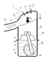
- FIG. 1 is a schematic cross-sectional explanatory view showing the entire working gas generator in the present invention.
- the working gas generator 1 of the present invention is a device for supplying the working gas K to a device using the working gas K as a power source, and is a cylinder block comprising a cylinder head 10, a cylinder 20, and a housing case 60. And a crank transmission mechanism including a piston 30, a connecting rod 40, and a rotating rotor 50.
- a fuel injector 12 that electronically injects fuel N such as gasoline in an atomized state or a vaporized state
- an air injector 13 that electronically injects air E compressed by a compressor or the like
- a spark plug 14 for electrical ignition.
- the fuel injector 12 includes a needle valve that is electrically opened and closed inside. When the valve is opened by the action of a plunger core, an electromagnet, and a spring, the fuel injector 12 is fed from a fuel injection pump (high-pressure fuel pump) from a tip injection port.
- a fuel injection pump high-pressure fuel pump
- This is an in-cylinder fuel injection device that performs electronic control injection of high-pressure fuel N at the timing of the air injector 13.
- the air injector 13 has a needle valve that is electrically opened and closed inside, and when the valve is opened by the action of a plunger core, an electromagnet, and a spring, a high pressure is sent from an air compression pump (compressor pump) from the tip injection port. It is a cylinder air injection device which injects the air E of this by electronic control.
- the cylinder 20 includes a working gas scavenging manifold 21 from which the working gas K is discharged at a predetermined position below the side wall, and a step portion 22.
- the fuel having a high flame propagation speed such as gasoline or hydrogen, has an instantaneous expansion time, and the piston 30 only needs to receive sufficient downward stress due to the instantaneous pressure change to ensure a sealed state in the cylinder 20.
- the stroke amount only needs to have a slight step portion 22 as shown in the drawing. However, since the ignition timing is advanced in the range of 10 to 25 degrees, the clearance C is secured so that the piston head 31 does not collide with the stepped portion 22 at the actual top dead center. Needless to say.
- the upper opening position of the internal passage of the working gas scavenging manifold 21 sufficiently receives the downward stress due to the instantaneous pressure change of the air-fuel mixture, and opens after the piston 30 starts to descend.
- the position of the bottom opening of the internal passage of the working gas scavenging manifold 21 is such that the piston 30 is continuously connected to the gentle inclined surface of the piston head 31 at the bottom dead center. Position to form.
- the cooling of the cylinder 20 is not shown, it is possible to use an air age or a water-cooling method using a heat sink such as a heat sink.
- the piston 30 is formed in a gently curved surface in which the shape of the piston head 31 is inclined downward toward the operating gas scavenging manifold 21 side, and is reciprocated by a crank transmission mechanism including a connecting rod 40 and a rotating rotor 50. It serves as a valve for discharging combustion gas. Since the piston 30 according to the present invention does not compress the air-fuel mixture in the cylinder 20, no compression ring is required. However, although not shown, it is also effective to provide an oil ring as necessary.
- the piston head 31 has a deformed shape of a convex head in which a so-called zenith is raised in a mountain shape, and is formed in a gentle curved surface inclined downward toward the working gas scavenging manifold 21 side.
- the explosion / expansion energy is guided to the operating gas scavenging manifold 21 by its gentle curved surface.
- the connecting rod 40 has a small end 41 serving as a piston pin insertion portion for connection to the piston 30 at one end, and a big end 51 serving as an insertion portion by a crank pin for connection to the rotating rotor 50 at the other end. , And serves to change the reciprocating motion of the piston 30 into a rotational motion.
- the rotary rotor 50 has a configuration similar to that of a power transmission shaft generally called a crankshaft. However, since the idea of an output shaft is strong in the name of the crankshaft, the rotary rotor 50 is used in this document as described above.
- the rotary rotor 50 is installed in a journal portion in the housing case 60 via a metal, a bearing, or the like.
- the journal portion is configured such that the shaft core 52 is offset by a predetermined distance R in the direction opposite to the operating gas scavenging manifold 21. (Such as an offset cylinder in which the conventional crankshaft is slightly shifted from the center position of the piston pin).
- a balance weight 51 for preventing vibration is provided on the opposite side of the outer circumferential circle connected to the connecting rod 40, and the vibration is suppressed by offsetting the inertial force related to the weight of the piston 30 and the connecting rod 40 so as to perform a linear operation.
- the piston 30 is changed to a smooth rotational motion.
- the offset amount of the predetermined distance R is a value obtained by multiplying the length M by sin 25 when the length from the axis 52 of the rotary rotor to the axis of the big end 42 of the connecting rod 40 is M. Become.
- the working gas generator 1 intends to use the explosion / expansion energy of the combustion chamber 11 as fluid operation energy, and the piston 30 and the connecting rod driven by a part of the explosion / expansion energy of the combustion chamber 11.
- the crank transmission mechanism composed of 40 and the rotary rotor 50 is not used as a power transmission mechanism, but is provided for the purpose of acting as an operating valve for guiding the operating gas K to the operating gas scavenging manifold 21. is there.
- FIG. 2 is a schematic cross-sectional explanatory view showing a combustion chamber forming (compression) step of the working gas generator in the present invention.
- the combustion chamber formation (compression) step the rotary rotor 50 rotates upward due to the inertia of the explosion / expansion energy in the combustion chamber 11, and the small end 41 of the connecting rod 40 at the position of the piston pin and the outer peripheral surface of the rotary rotor 50.
- the piston 30 ascends toward the top dead center H until the large end 42 of the connecting rod 40 and the shaft core 52 of the rotary rotor 50 are in a straight line.
- This is a process in which the fuel N and the compressed air E are electronically controlled and injected by the fuel injector 11 and the air injector 12 provided in the cylinder head 10 at the timing when the combustion chamber 11 is formed to the minimum volume by closing.
- FIG. 3 is a schematic cross-sectional explanatory view showing an ignition process of the working gas generator in the present invention.
- the combustion chamber 11 is formed to a minimum volume, the small end 41 of the connecting rod 40 at the position of the piston pin, the large end 42 of the connecting rod 40 positioned on the outer peripheral surface of the rotating rotor 50, and the axis 52 of the rotating rotor 50.
- This is a step in which the spark plug 14 distributed by the distributor is electrically ignited at a position where the advance angle ⁇ is 10 to 25 degrees from the position where is straight to the explosion / expansion stroke side.
- FIG. 4 is a schematic cross-sectional explanatory view showing an explosion / expansion process of the working gas generator in the present invention.
- the working gas K exploding / expanding in the combustion chamber 11 pushes down the piston head 10 toward the bottom dead center L, and rotates the rotary rotor 50 downward with some explosion / expansion energy. It is.
- FIG. 5 is a schematic cross-sectional explanatory view showing a scavenging process of the working gas generator in the present invention.
- the combustion chamber 11 is exploded and exhausted at the same time.
- the working gas K generated by the explosion and expansion energy of the combustion chamber 11 has a gentle curved surface in which the shape of the upper end portion 32 of the piston 30 is inclined downward.
- This is a process in which the turbine, the rotor, the propeller, the fan, the blade, the rotor, and the like that are guided and rotated scavengingly toward the working gas scavenging manifold 21 side are rotationally driven.
- the combustion cycle of the internal combustion engine configured as described above will be briefly described.
- the chamber 30 is formed with a configuration in which the piston 30 completes the reciprocating cycle in the chamber forming (compression) step, the ignition step, the explosion / expansion stroke, and the scavenging step.
- the operating gas generator of the present invention is small, light, and has high output, it can be used as a drive source for a wind power generator, or supply high-speed and high-pressure operating gas to the turbine blades regardless of the rotational speed of the internal combustion engine. It can be used in various fields, such as a turbocharger that can be supplied, a high-temperature expansion gas supply device for balloons, etc., and it is understood that the industrial applicability of the operating gas generator of the present invention is large.
Landscapes
- Engineering & Computer Science (AREA)
- Chemical & Material Sciences (AREA)
- Combustion & Propulsion (AREA)
- Mechanical Engineering (AREA)
- General Engineering & Computer Science (AREA)
- Combustion Methods Of Internal-Combustion Engines (AREA)
- Electrical Control Of Ignition Timing (AREA)
- Cylinder Crankcases Of Internal Combustion Engines (AREA)
- Combined Controls Of Internal Combustion Engines (AREA)
Abstract
L'invention porte sur un dispositif de génération de gaz de travail, lequel dispositif fournit un gaz de travail à une unité de puissance ayant un gaz de travail comme source de force motrice. A cet effet, l'invention porte sur un dispositif de génération de gaz de travail pour fournir un gaz de travail à un dispositif qui a un gaz de travail comme source de force motrice, lequel dispositif de génération est constitué par une tête de cylindre, un bloc-cylindres obtenu à partir d'un cylindre et d'un carter, et un mécanisme de transmission à vilebrequin obtenu à partir d'un piston, d'une bielle et d'un rotor rotatif. Le dispositif est allumé à une position d'avance d'allumage de 10 à 25° sur le côté de course d'expansion à partir de la position proche du point mort haut où les positions de liaison du piston, de la bielle et du rotor rotatif et la position de l'axe de rotor rotatif forment une ligne droite. Le dispositif utilise un moyen configuré de telle sorte que le piston effectue un processus de formation de chambre de combustion (compression), un processus d'allumage, un processus d'explosion/expansion et un processus de balayage en un cycle de va-et-vient unique.
Applications Claiming Priority (2)
| Application Number | Priority Date | Filing Date | Title |
|---|---|---|---|
| JP2011195521A JP5002721B1 (ja) | 2011-09-08 | 2011-09-08 | 動作気体発生装置 |
| JP2011-195521 | 2011-09-08 |
Publications (1)
| Publication Number | Publication Date |
|---|---|
| WO2013035367A1 true WO2013035367A1 (fr) | 2013-03-14 |
Family
ID=46793996
Family Applications (1)
| Application Number | Title | Priority Date | Filing Date |
|---|---|---|---|
| PCT/JP2012/059273 Ceased WO2013035367A1 (fr) | 2011-09-08 | 2012-04-05 | Dispositif de génération de gaz de travail |
Country Status (2)
| Country | Link |
|---|---|
| JP (1) | JP5002721B1 (fr) |
| WO (1) | WO2013035367A1 (fr) |
Cited By (1)
| Publication number | Priority date | Publication date | Assignee | Title |
|---|---|---|---|---|
| IT202400005851A1 (it) * | 2024-03-15 | 2025-09-15 | Univ Degli Studi Di Firenze | Motore a combustione interna a due tempi comprendente un sistema di iniezione ottimizzato |
Families Citing this family (1)
| Publication number | Priority date | Publication date | Assignee | Title |
|---|---|---|---|---|
| DK178404B1 (en) * | 2014-07-17 | 2016-02-08 | Man Diesel & Turbo Deutschland | Large slow-running turbocharged two-stroke self-igniting internal combustion engine with a starting air system |
Citations (3)
| Publication number | Priority date | Publication date | Assignee | Title |
|---|---|---|---|---|
| JPS50125108A (fr) * | 1974-03-20 | 1975-10-01 | ||
| JPH0868331A (ja) * | 1994-08-29 | 1996-03-12 | Mitsubishi Heavy Ind Ltd | 2サイクルガソリンエンジンの燃焼装置 |
| JP2002054457A (ja) * | 2000-08-10 | 2002-02-20 | Takashi Nanjo | 断続燃料噴射型回転式内燃機関 |
-
2011
- 2011-09-08 JP JP2011195521A patent/JP5002721B1/ja not_active Expired - Fee Related
-
2012
- 2012-04-05 WO PCT/JP2012/059273 patent/WO2013035367A1/fr not_active Ceased
Patent Citations (3)
| Publication number | Priority date | Publication date | Assignee | Title |
|---|---|---|---|---|
| JPS50125108A (fr) * | 1974-03-20 | 1975-10-01 | ||
| JPH0868331A (ja) * | 1994-08-29 | 1996-03-12 | Mitsubishi Heavy Ind Ltd | 2サイクルガソリンエンジンの燃焼装置 |
| JP2002054457A (ja) * | 2000-08-10 | 2002-02-20 | Takashi Nanjo | 断続燃料噴射型回転式内燃機関 |
Cited By (2)
| Publication number | Priority date | Publication date | Assignee | Title |
|---|---|---|---|---|
| IT202400005851A1 (it) * | 2024-03-15 | 2025-09-15 | Univ Degli Studi Di Firenze | Motore a combustione interna a due tempi comprendente un sistema di iniezione ottimizzato |
| WO2025191509A1 (fr) * | 2024-03-15 | 2025-09-18 | Università Degli Studi Di Firenze | Moteur à combustion interne à deux temps comprenant un système d'injection optimisé |
Also Published As
| Publication number | Publication date |
|---|---|
| JP5002721B1 (ja) | 2012-08-15 |
| JP2013057279A (ja) | 2013-03-28 |
Similar Documents
| Publication | Publication Date | Title |
|---|---|---|
| US5970924A (en) | Arc-piston engine | |
| US7556014B2 (en) | Reciprocating machines | |
| JP4951143B1 (ja) | 三出力軸型の内燃機関 | |
| CN1969112A (zh) | 独立燃烧室式内燃机 | |
| JP4286419B2 (ja) | ピストン形内燃機関 | |
| JP5002721B1 (ja) | 動作気体発生装置 | |
| JP4951145B1 (ja) | 二軸出力型の逆v型略対向エンジン | |
| US7621253B2 (en) | Internal turbine-like toroidal combustion engine | |
| US6021746A (en) | arc-piston engine | |
| JP2004530828A (ja) | ロータリー内燃機関 | |
| CN212130616U (zh) | 一种压爆内燃式高副传动发电机构 | |
| CA2328671A1 (fr) | Moteur a combustion interne a piston rotatif a un temps a mecanisme de compression de traction et chambre de combustion multiple | |
| US20090320794A1 (en) | Novel Internal Combustion Torroidal Engine | |
| US6941903B2 (en) | System and method for adding air to an explosion chamber in an engine cylinder | |
| WO2014209149A1 (fr) | Moteur à combustion interne | |
| RU118690U1 (ru) | Двигатель внутреннего сгорания | |
| SureshBabu et al. | Analysis of a Single Cylinder Combustion Engine Using CFD | |
| CN116025464A (zh) | 旋转活塞式转子发动机 | |
| KR102066306B1 (ko) | 내연기관 및 내연기관의 작동 방법 | |
| KR101129125B1 (ko) | 혼합기체압축기 | |
| KR100475809B1 (ko) | 실린더 내 스월 발생장치 | |
| KR100514632B1 (ko) | 회전식 엔진 구조 | |
| WO2008073082A2 (fr) | Moteur à combustion interne toroïdal de type à turbine | |
| CN103410622A (zh) | Kr汽油内燃发动机 | |
| CN85102435A (zh) | 一冲程发动机 |
Legal Events
| Date | Code | Title | Description |
|---|---|---|---|
| 121 | Ep: the epo has been informed by wipo that ep was designated in this application |
Ref document number: 12829269 Country of ref document: EP Kind code of ref document: A1 |
|
| NENP | Non-entry into the national phase |
Ref country code: DE |
|
| 122 | Ep: pct application non-entry in european phase |
Ref document number: 12829269 Country of ref document: EP Kind code of ref document: A1 |