WO2013038687A1 - Outil d'insertion de lentille intraoculaire - Google Patents
Outil d'insertion de lentille intraoculaire Download PDFInfo
- Publication number
- WO2013038687A1 WO2013038687A1 PCT/JP2012/005859 JP2012005859W WO2013038687A1 WO 2013038687 A1 WO2013038687 A1 WO 2013038687A1 JP 2012005859 W JP2012005859 W JP 2012005859W WO 2013038687 A1 WO2013038687 A1 WO 2013038687A1
- Authority
- WO
- WIPO (PCT)
- Prior art keywords
- intraocular lens
- protrusion
- contact
- optical
- instrument body
- Prior art date
- Legal status (The legal status is an assumption and is not a legal conclusion. Google has not performed a legal analysis and makes no representation as to the accuracy of the status listed.)
- Ceased
Links
Images


Classifications
-
- A—HUMAN NECESSITIES
- A61—MEDICAL OR VETERINARY SCIENCE; HYGIENE
- A61F—FILTERS IMPLANTABLE INTO BLOOD VESSELS; PROSTHESES; DEVICES PROVIDING PATENCY TO, OR PREVENTING COLLAPSING OF, TUBULAR STRUCTURES OF THE BODY, e.g. STENTS; ORTHOPAEDIC, NURSING OR CONTRACEPTIVE DEVICES; FOMENTATION; TREATMENT OR PROTECTION OF EYES OR EARS; BANDAGES, DRESSINGS OR ABSORBENT PADS; FIRST-AID KITS
- A61F2/00—Filters implantable into blood vessels; Prostheses, i.e. artificial substitutes or replacements for parts of the body; Appliances for connecting them with the body; Devices providing patency to, or preventing collapsing of, tubular structures of the body, e.g. stents
- A61F2/02—Prostheses implantable into the body
- A61F2/14—Eye parts, e.g. lenses or corneal implants; Artificial eyes
- A61F2/16—Intraocular lenses
- A61F2/1662—Instruments for inserting intraocular lenses into the eye
- A61F2/167—Instruments for inserting intraocular lenses into the eye with pushable plungers
Definitions
- the present invention relates to an intraocular lens insertion device that is provided with a built-in intraocular lens and used to insert the built-in intraocular lens into the eye.
- Patent Document 1 a technique using an intraocular lens insertion device as described in Patent Document 1 has been widely adopted.
- a push-out member that is inserted into the eye through the incision wound at the distal end of the insertion tube provided at the distal end of the tubular instrument body and inserted from the proximal end of the instrument body,
- An intraocular lens is inserted into the eye by deforming the intraocular lens housed in the mounting portion to a small size and pushing it out from the distal end opening of the insertion tube.
- an intraocular lens insertion device an intraocular lens that is provided separately from the intraocular lens and is used by setting an intraocular lens that is separately packed at the time of treatment to the insertion device is used.
- Some are provided with built-in.
- the intraocular lens is sterilized and packed and stored until use.
- Patent Document 1 Japanese Patent Application Laid-Open No. 2006-181269
- Patent Document 2 a protective wall portion that surrounds the periphery of an intraocular lens is protruded from the mounting portion when not in use, and the intraocular lens is caused by malfunction of a push member. It has been proposed to prevent the stress from being applied and to remove the protective wall portion during use and push the intraocular lens by the pushing member.
- the intraocular lens is composed of an optical part and a pair of support parts extending to both sides of the optical part, and the pair of support parts are mounted so as to extend to the front end side and the rear end side of the instrument body. Built in the mounting unit. Therefore, when the intraocular lens is pushed out to the insertion tube portion by the push member, the behavior of the intraocular lens inserted into the sac differs depending on how the front support portion and the rear support portion are bent or bent. In some cases, the support portion may be damaged.
- the hardness of the support part easily changes due to the influence of room temperature, etc. It becomes difficult to further stabilize the posture of the support portion.
- Patent Document 2 when the intraocular lens is pushed out by the pushing member, the front support part is brought into contact with the protrusion and bent in a U shape toward the optical part.
- the structure to be made is proposed. Thereby, when releasing from an insertion cylinder part, a front support part becomes difficult to float, and an intraocular lens can be stably inserted in a bag.
- the front support portion is not engaged with the protrusion and is not bent into a desired shape due to the built-in state displaced by the hardness of the support portion or transportation. There was a case.
- the present invention has been made in the background of the above-described circumstances, and the solution is to provide a novel, stable control of the deformation state of the support portion of the intraocular lens. It is to provide an insertion device for an intraocular lens having a structure.
- the first aspect of the present invention is a cylindrical instrument body provided with a placement portion on which an intraocular lens having an optical portion and a pair of support portions extending from both sides of the optical portion is placed;
- An extrusion member that is inserted from the rear end of the instrument body and pushes the intraocular lens to an insertion tube provided at the distal end of the instrument body, while the pair of support parts of the intraocular lens includes
- the intraocular lens insertion device provided in a state where the intraocular lens is built in the mounting portion so as to extend to the front end side and the rear end side of the device main body, the device main body which is the pair of support portions At least one of the front support part extending to the front end side and the rear support part extending to the rear end side of the instrument main body is brought into contact with the contact protrusion disposed in the mounting part and deformed in advance. It is characterized by this.
- the intraocular lens insertion device structured according to this aspect, at least one of the front support portion and the rear support portion of the intraocular lens is brought into contact with the contact protrusion and bent or bent, It is built in the mounting portion in a deformed state.
- the support portion is in a state of being deformed into a desired shape. It becomes possible to prevent damage to the inner lens and to stabilize the behavior of the intraocular lens in the sac.
- the intraocular lens insertion device with a conventional structure stabilizes the behavior of the intraocular lens during the operation by transporting and storing the insertion device and applying a load as little as possible to the built-in intraocular lens. It was thought to make it.
- the present invention is based on a completely new idea that has not been heretofore, and when the insertion device is transported or stored, the front support part and / or the back support part of the built-in intraocular lens is actively deformed, An epoch to improve the shape of the support part of the intraocular lens that is pushed out from the insertion instrument during the treatment by preliminarily attaching the deformed heels to control the behavior of the support part and the behavior of the intraocular lens.
- transformation to the front support part and / or back support part of an intraocular lens is bent or curved to the optical part side by making a front support part and / or back support part contact a contact protrusion. It includes any of the embodiments, the embodiment in which the optical portion is deformed to one side on both sides in the optical axis direction, and the combination of these.
- the intraocular lens insertion device in the intraocular lens insertion device according to the first aspect, at least one of the front support portion and the rear support portion is in contact with the contact protrusion, and the optical It is deformed in advance on the part side.
- the intraocular lens insertion device structured according to this aspect, at least one of the front support portion and the rear support portion of the intraocular lens is brought into contact with the contact protrusion and bent or bent, It is built in the mounting part in a state of being deformed to the optical part side.
- the intraocular lens is built in the mounting portion in a state where at least one support portion is deformed in advance to the optical portion side, and an intraocular lens insertion device is provided. Therefore, when the intraocular lens is pushed out from the instrument body by the pushing member during the operation, the support portion is in a state of being deformed into a desired shape. It becomes possible to prevent damage to the inner lens and to stabilize the behavior of the intraocular lens in the sac.
- the intraocular lens when the intraocular lens is pushed out by the push-out member by deforming the front end of the front support part into the optical part side by making contact with the contact protrusion, the optical part is bent and deformed in a convex shape.
- a so-called tacking state in which the front end portion of the front support portion is held can be advantageously produced.
- the front support part when the intraocular lens is released into the sac from the insertion tube part, the front support part is inserted first and the intraocular lens is rotated around the sac around the ocular lens, thereby preventing the eye
- the inner lens can be stably held in the sac.
- the lens is bent and deformed into a convex shape when the intraocular lens is pushed out by the pushing member.
- the tip of the rear support part into contact with the abutment protrusion and preliminarily folding the rear part of the optical part.
- the lens is bent and deformed into a convex shape when the intraocular lens is pushed out by the pushing member.
- the rear end of the rear support portion is brought into contact with the contact protrusion and deformed so as to approach the front side of the optical portion in advance.
- the intraocular lens can be pushed out in a state where the rear support part extends behind the optical part while avoiding the folding of the part.
- the abutting protrusion is disposed at an arbitrary position of the mounting portion, and includes both a protrusion provided integrally with the instrument main body and a protrusion provided so as to be removable from the instrument main body. Further, the deformation of each support part is shifted so that each support part approaches toward the optical part side, and a constant contact pressure toward the optical part side is applied by contact with the contact protrusion. It affects the support part and does not cause plastic deformation of each support part.
- the placement portion opens to a placement surface on which the intraocular lens is placed.
- a plurality of through holes are provided, and a holding member having the contact protrusion and the holding protrusion is removably assembled, and the holding protrusion of the holding member protrudes from the through hole of the mounting surface.
- the front support portion is configured to hold the intraocular lens from below while the corresponding contact protrusion of the holding member protrudes from the through hole onto the placement surface, and is in contact with the contact protrusion.
- at least one of the rear support portions is deformed in advance to the optical portion side.
- the contact protrusion is provided on the holding member that is removably assembled to the mounting portion, and the contact protrusion is disposed in the mounting portion through the through hole that opens in the mounting surface. did.
- the holding projection is assembled to stably hold the intraocular lens, and at any location on the front and / or rear support portions.
- the support protrusions can be brought into contact with each other and the support portions can be deformed in advance to the optical portion side.
- the holding member can be removed from the mounting portion by removing the holding member from the placing portion, and the abutting projection and the like can be removed from the placing portion.
- the contact protrusion can be set at an arbitrary place without considering interference with the pushing member.
- the abutment protrusion can be projected on a path in the extruding direction of the extruding member, and the abutting protrusion can serve as a lock mechanism for the extruding member when not in use.
- an intraocular lens insertion device according to any one of the first to third aspects, wherein the intraocular lens is made of a soft synthetic resin material. Is.
- the pair of support portions have flexibility. Therefore, if the support portion is deformed in any direction by the contact protrusion in advance during transportation and storage, the deformed shape can be sufficiently retained even after the contact protrusion is removed, and the extrusion by the extrusion member is possible. Sometimes the desired deformation of the support can be realized.
- the placement surface of the placement unit on which the intraocular lens is placed is provided.
- the abutment protrusion is disposed adjacent to the optical part at one end in the width direction of the mounting surface on the front side of the instrument body on the front end side.
- the front end portion of the front support portion is in contact with the surface facing the optical portion.
- the front support part since the front end of the front support part is brought into contact with the front contact protrusion and brought close to the optical part, the front support part is placed on the optical part side while reducing the load on the front support part. Can be transformed into.
- the front contact protrusion is provided at one end in the width direction of the mounting portion, even when the front contact protrusion is formed integrally with the mounting portion, avoid interference with the pushing member. Can be arranged.
- the placement surface of the placement unit on which the intraocular lens is placed is provided.
- the abutting projection is disposed on the other side in the width direction of the placement surface so as to protrude from the placement surface in the vicinity of the optical portion on the rear side located on the rear end side of the instrument body.
- the distal end portion of the rear support portion is deformed to the front side of the intraocular lens in contact with the corresponding contact protrusion.
- the rear support portion since the front end portion of the rear support portion is brought into contact with the rear contact protrusion and is brought closer to the optical portion, the rear support portion is placed on the optical portion side while reducing the load on the rear support portion. Can be transformed into In addition, since the rear abutting protrusion protrudes on the placement surface, the tip of the rear support portion is deformed to the front side of the intraocular lens (the surface side positioned on the placement surface). It can be controlled easily. Further, since the rear contact protrusion is provided at the other end in the width direction of the mounting portion, even when the rear contact protrusion is integrally formed on the mounting portion, avoid interference with the pushing member. Can be arranged.
- a lid member that covers the opening of the placement portion with respect to the device body On the rear side of the bottom surface of the lid member located on the rear end side of the instrument body, the contact protrusion that protrudes from the bottom surface toward the rear support portion is provided, The tip of the rear support portion is deformed to the rear side of the intraocular lens by the contact protrusion.
- the rear support portion since the front end portion of the rear support portion is brought into contact with the rear contact protrusion and is brought closer to the rear surface side of the optical portion, the rear support portion is reduced while reducing the load on the rear support portion.
- the optical part can be deformed to the rear surface side.
- the rear abutment protrusion protrudes on the back surface side of the lid member, the rear support portion can be reliably deformed to the rear surface side of the optical portion in a state where the mounting portion is covered with the lid member. it can.
- the intraocular lens is incorporated in a state where at least one of the front support portion and the rear support portion of the intraocular lens is brought into contact with the contact protrusion and deformed in advance. Since it is provided, the support part of the intraocular lens pushed out from the pushing member during the treatment can be deformed into a desired shape, and the behavior of the support part and further the intraocular lens can be controlled effectively.
- the side view of the insertion instrument shown in FIG. The principal part enlarged top view of the mounting part which comprises the insertion instrument shown in FIG.
- the top view of the holding member which comprises the insertion instrument shown in FIG. The side view of the holding member shown in FIG.
- the upper surface explanatory drawing which expands and shows the principal part of the insertion instrument shown in FIG. VII-VII longitudinal section enlarged view of FIG. 6
- the principal part enlarged top view which shows the other aspect of the mounting part which comprises the insertion instrument of this invention.
- the figure corresponding to FIG. It is a principal part enlarged view which shows the other aspect of the insertion instrument of this invention, Comprising:
- the figure corresponding to FIG. FIG. 11 is an enlarged view of a main part in the XI-
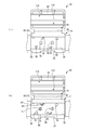
- FIGS. 1 and 2 show an intraocular lens insertion device 10 as an embodiment of the present invention.
- the intraocular lens insertion instrument 10 is made of a synthetic resin, and is inserted from a cylindrical instrument body 16 having a placement portion 14 on which the intraocular lens 12 is placed, and a rear end portion 18 of the instrument body 16.
- the push-out member 22 that pushes the intraocular lens 12 to the insertion tube portion 20 provided at the distal end portion of the instrument main body 16 is provided, and the intraocular lens 12 is provided in advance.
- “front” refers to the pushing direction of the pushing member 22 (left direction in FIG. 1)
- “upward” refers to the up direction in FIG.
- the left-right direction refers to the left-right direction in the top view of the intraocular lens insertion device 10 (upper is right and lower is left in FIG. 1).
- the instrument main body 16 has a main body cylinder portion 24 having a substantially cylindrical shape.
- a through-hole 26 that penetrates in the axial direction with a substantially rectangular cross-sectional shape is formed inside the main body cylinder portion 24.
- a plate-like portion 28 that extends in a direction orthogonal to the extending direction of the main body cylinder portion 24 is integrally formed at a position slightly forward from the rear end portion of the main body cylinder portion 24.
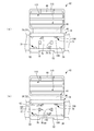
- FIG. 3 shows the placement unit 14.
- the mounting portion 14 is formed with a concave groove 32 extending in the axial direction with a width that is slightly larger than the diameter of the optical portion 30 of the intraocular lens 12 shown in FIG.
- the concave groove 32 has an axial length dimension that is slightly larger than the maximum width dimension (left-right dimension in FIG. 1) including a pair of support parts 34a, 34b that integrally extend from both sides of the optical part 30 of the intraocular lens 12. It is formed with.
- the pair of support portions 34a and 34b the one that extends to the distal end side of the instrument body 16 is referred to as a front support portion 34a, and the one that extends to the rear end side of the instrument body 16 is a rear support portion. It is called 34b.
- the concave groove 32 has an opening 36 opened upward, and a mounting surface 38 is formed on the bottom surface thereof.
- the placement surface 38 has a width dimension slightly larger than the minimum width dimension (the vertical dimension in FIG. 1) of the intraocular lens 12, and is larger than the maximum width dimension (the horizontal dimension in FIG. 1) of the intraocular lens 12. Is also a flat surface having a large axial length dimension.
- the height position of the mounting surface 38 is located higher than the height position of the bottom surface of the through hole 26 in the main body cylinder portion 24, and the front edge of the through hole 26 in the main body cylinder portion 24 is A wall portion 40 (see FIG. 2) that extends upward from the bottom surface of the through hole 26 and is connected to the rear end edge portion of the placement surface 38 is formed.
- the concave groove 32 communicates with the through hole 26, and the width dimension of the concave groove 32 is substantially equal to the width dimension of the through hole 26.
- a cover member 42 as a lid is integrally formed with the instrument body 16 on the side of the concave groove 32 (on the right side in the present embodiment).
- the cover member 42 has an axial dimension substantially equal to the axial dimension of the concave groove 32 and is formed with a width dimension slightly larger than the width dimension of the concave groove 32.
- the cover member 42 is connected to the instrument main body 16 by a substantially thin plate-like connecting portion 44 formed by extending the upper end edge of the mounting portion 14 to the side (in the present embodiment, the right side).
- the connecting portion 44 is thinnest at a bent portion 46 extending in the axial direction of the instrument body 16 at a substantially central portion in the width direction, and can be bent at the bent portion 46.
- the cover member 42 is configured to be able to cover the opening 36 by bending the connecting portion 44 and overlapping the concave groove 32.
- An engagement piece 48 is formed to project from the edge of the cover member 42 opposite to the connecting portion 44, while the end of the mounting portion 14 opposite to the cover member 42 projects outward.
- a protruding edge 50 is formed, and an engagement notch 52 is formed at a position corresponding to the engagement piece 48 in the protruding edge 50.
- the holding member 54 is detachably provided in a state where the intraocular lens 12 is supported under the mounting surface 38 of the mounting unit 14 having such a structure.
- the holding member 54 is configured as a separate body from the instrument body 16, and a pair of side wall portions 56, 56 are connected by a connecting plate portion 58 formed integrally between the opposing surfaces. It is structured.
- the separation distance of the outer surface of the side wall portion 56 is substantially equal to the radial dimension of the optical portion 30 of the intraocular lens 12.
- a leg plate portion 60 that is bent outward is integrally formed at the lower edge of each side wall portion 56.
- the leg plate portion 60 has a shape in which a central portion in the axial direction is slightly recessed in a top view.
- first holding projections 62 and 62 projecting upward with a substantially arc shape in a top view are integrally formed at the upper end portions of the respective side wall portions 56 and 56.
- a peripheral wall 64 is integrally formed on the outer side of the upper end surface of the first holding projection 62 on the inner side of the holding member 54.
- the separation distance of the peripheral wall 64 is slightly larger than the diameter of the optical part 30 of the intraocular lens 12.
- a pair of second holding projections 66 and 66 projecting upward in a rectangular shape in a top view are mutually opposite in the longitudinal direction of the holding member 54 (left and right direction in FIG. 4).
- the height position of the upper end surface of the second holding projection 66 is equal to the height position of the upper end surface of the first holding projection 62.
- Each of the second holding projections 66 includes a projection main body 68 projecting from the connecting plate portion 58, a peripheral wall 70 projecting from the upper end surface of the projection main body 68, and the second main body projection 68 in the opposing direction of the second holding projection 66.
- each peripheral wall 70 and each engagement portion 71 have a width dimension substantially equal to the width dimension of the projection main body 68.
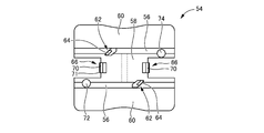
- the holding member 54 is close to the side wall portion 56 that is one end portion in the width direction (the lower side in FIG. 4) on the front side that is located closer to the distal end side of the instrument body 16 than the second holding projection 66.
- a substantially cylindrical front abutting projection 72 with which the front support portion 34a abuts is integrally provided.
- the holding member 54 is close to the side wall portion 56 which is the other end portion in the width direction (upper side in FIG. 4) on the rear side located on the rear end side of the instrument body 16 with respect to the second holding projection 66.
- a substantially cylindrical rear abutting projection 74 with which the rear support portion 34b abuts is integrally projected.
- the holding member 54 having such a structure is assembled from the lower side of the mounting surface 38 of the instrument main body 16. Specifically, the mounting surface 38 of the instrument body 16 is formed with through holes 76, 78, and 80 that open to the mounting surface 38 on which the intraocular lens 12 is mounted (see FIG. 3). Then, the first and second holding projections 62 and 66 of the holding member 54 are inserted through the through holes 76 and 78 of the mounting surface 38 and protruded, so that the holding member 54 removes the outer portion of the optical unit 30 of the intraocular lens 12. The peripheral edge is supported from below. Further, the front abutting protrusion 72 and the rear abutting protrusion 74 are arranged so as to protrude from the mounting surface 38 through the through hole 80.
- the through holes 76 and 78 have substantially the same cross-sectional shape as the first and second holding projections 62 and 66, and are formed through the mounting surface 38 with a slightly larger outer dimension.
- the through hole 80 has a circular cross section corresponding to the front and rear contact protrusions 72 and 74 and is formed to penetrate the mounting surface 38 with a slightly larger outer diameter. Then, the first and second holding projections 62 and 66 are inserted into the through holes 76 and 78 from the lower side of the placement surface 38 and protrude on the placement surface 38.
- the engaging portion 71 provided on the second holding projection 66 protrudes on the placement surface 38 and is locked to the upper surface of the placement surface 38, so that the holding member 54 is outside the instrument body 16.
- the front and rear abutment protrusions 72 and 74 are also inserted into the through hole 80 from the lower side of the placement surface 38 and project on the placement surface 38 simultaneously with the first and second holding projections 62 and 66. Is done.
- the engagement by the engagement portion 71 is formed so that it can be pulled out by pulling the holding member 54 below the placement surface 38.
- an insertion tube portion 20 that extends toward the front in the axial direction of the instrument body 16 is integrally formed in front of the placement portion 14.
- the insertion tube portion 20 has a tapered shape that gradually tapers from the placement portion 14 side toward the distal end portion in the extending direction as a whole, and has a tapered shape penetrating the entire length in the extending direction.
- a through hole 84 is formed.
- the through hole 84 communicates with the mounting portion 14 by connecting a base end opening 86 opened to the mounting portion 14 side to the mounting surface 38.
- the base end opening 86 has a flat and substantially elliptical cross section in which the bottom surface 88 is a flat surface and the top surface is a substantially arc shape.
- the front end opening 90 provided at the front end of the through hole 84 has an oblique opening shape in a side view in which the upper surface extends forward from the bottom surface.
- the bottom surface 88 is formed with an introduction protrusion 92 that extends in the axial direction of the instrument body 16 with the widthwise center portion of the bottom surface 88 interposed therebetween.
- the introduction protrusions 92 have a linear shape that protrudes slightly upward from the bottom surface 88 and extends parallel to each other.
- the protrusion height of the introduction protrusion 92 is gradually increased toward the front in the axial direction of the instrument body 16, and is flush with the bottom surface 88 at the rear end portion of the proximal end opening 86. .
- the introduction protrusions 92 are arranged substantially parallel to each other at a predetermined distance in the direction perpendicular to the axis of the instrument body 16 with the center in the width direction of the bottom surface 88 interposed therebetween. Is preferably slightly larger than the width of the distal end portion of the extrusion member 22. In particular, in this embodiment, the width is slightly larger than the width of the rod-shaped portion 94 of the extrusion member 22.
- the instrument main body 16 in the present embodiment is configured as a single member in which the main body cylinder part 24, the placement part 14, the cover member 42, and the insertion cylinder part 20 are integrally molded.
- a holding member 54 configured separately from the main body 16 is assembled from below the placement surface 38.
- the pushing member 22 is inserted into the through hole 26 from the rear of the instrument body 16.
- the push-out member 22 has a substantially rod shape having an axial length dimension slightly larger than the axial length dimension of the instrument body 16, and has a substantially cylindrical action portion 96 and a substantially rectangular rod shape.
- the insertion portion 98 is integrally formed.
- the distal end portion of the pushing member 22 is inserted into the main body cylinder portion 24 of the device main body 16 from the rear, and the claw portion 100 is connected to the locking portion 102.
- the initial position locked in the locking hole 104 is set.
- the holding member 54 is attached to the instrument body 16 from below the placement surface 38 and temporarily held as described above.
- the holding member 54 is assembled to the instrument body 16, and the first holding projection 62, the second holding projection 66, the front contact projection 72, and the rear contact projection 74 of the holding member 54 protrude on the placement surface 38. Temporarily held in the finished state.
- the optical unit 30 of the intraocular lens 12 is placed on the upper end surfaces of the first holding protrusion 62 and the second holding protrusion 66.
- FIG. 6 only a necessary portion of the instrument main body 16 and a distal end portion of the pushing member 22 facing the intraocular lens 12, the holding member 54, and the placement portion 14 are shown for easy understanding.
- the intraocular lens 12 has the outer peripheral portion of the optical unit 30 in contact with the first and second holding projections 62 and 66, and the central portion has the first and second holding projections 62 and 66. 66 in a non-contact state.
- a second holding projection 66 projecting from the placement surface 38 is disposed oppositely in front of the rod-like portion 94 at the tip of the pushing member 22 in the axial direction (left direction in FIG. 6).
- a stopper that prevents the pushing member 22 from moving forward is configured by the second holding projection 66, and the pushing member 22 has the second holding projection 66 from above the placement surface 38 as described later. Unless you move backwards, you are prevented from moving forward.
- peripheral walls 64 and 70 formed on the first holding protrusion 62 and the second holding protrusion 66 are outside the optical unit 30 in the intraocular lens 12, and in particular in the present embodiment, formed on the first holding protrusion 62.
- the peripheral wall 64 sandwiches the intraocular lens 12 on both sides in an oblique direction with respect to the axial direction of the instrument main body 16, and the peripheral wall 70 formed on the second holding projection 66 connects the intraocular lens 12 to the axis of the instrument main body 16. It is provided so as to sandwich both sides of the direction. Thereby, the amount of displacement of the intraocular lens 12 with respect to the instrument body 16 in the axial direction and the axial direction is limited, and the intraocular lens 12 can be stably held.
- the optical unit 30 of the intraocular lens 12 is placed at a predetermined distance from the placement surface 38 in the placement state on the first and second holding projections 62 and 66, and is placed on the placement surface 38. On the other hand, it is held in a non-contact state.
- the front abutting protrusion 72 and the rear abutting protrusion 74 provided in the vicinity of the second holding protrusions 66 and 66 are optically applied to the intraocular lens 12 held by the first and second holding protrusions 62 and 66. It is arranged close to the part 30.
- the front support portion 34 a and the rear support portion 34 b are disposed so as to abut against the surfaces of the front contact protrusion 72 and the rear contact protrusion 74 facing the optical unit 30.
- the front support part 34a and the rear support part 34b are bent or curved so as to approach the optical part 30 side.
- the front support part 34a and the rear support part 34b of the intraocular lens 12 are in contact with the front contact protrusion 72 and the rear contact protrusion 74, respectively.
- the front contact protrusion 72 and the rear contact protrusion 74 are substantially cylindrical, and since there are no protrusions on the outer peripheral surface thereof, the contact pressure to the front contact protrusion 72 and the rear contact protrusion 74 is reduced. This advantageously prevents damage to the front support portion 34a and the rear support portion 34b.
- the method of bringing the front support part 34a and the rear support part 34b into contact with the front contact protrusion 72 and the rear contact protrusion 74 is arbitrary.
- the front end portions of the front support portion 34a and the rear support portion 34b having the shapes may be hooked on a rod-shaped member (not shown) and moved to contact the front contact protrusion 72 and the rear contact protrusion 74, respectively.
- the amount of displacement L (see FIG. 6) in the axial direction of the instrument body 16 before and after the deformation at the tip of each support portion 34a, 34b is preferably 0.05 to 3 mm, more preferably 0.5 to 2 mm.
- each support portion 34a, 34b is shifted so as to approach the optical portion 30, and each support portion 34a, 34b is caused by the contact reaction force to each contact protrusion 72, 74. 34b is pushed toward the optical unit 30 and deforms by bending, and does not cause plastic deformation.
- the rear abutment protrusion 74 has a stepped shape in which a notch 106 is provided upward from an intermediate portion in the projecting direction, and the rear support 34 b is formed on the step 108.
- An intermediate portion in the length direction is placed and supported on the upper side of FIG. 7, which is the front side of the optical unit 30, and the distal end portion of the rear support part 34 b is guided to the optical unit 30 side by the peripheral wall 109 of the notch 106.
- the optical unit 30 is deformed so as to approach the front side.
- the front support part 34a and the rear support part 34b of the intraocular lens 12 are in contact with the front contact protrusion 72 and the rear contact protrusion 74, respectively, and are deformed in advance so as to approach the optical unit 30 side.
- the intraocular lens 12 is built in the placement unit 14.
- the bent portion 46 is bent, and the opening 36 of the placement portion 14 is covered with the cover member 42, whereby the intraocular lens 12 is set in the instrument main body 16 in the accommodated state.
- the cover member 42 is maintained in the closed state by the engagement piece 48 being engaged with the engagement notch 52.
- the intraocular lens 12 is accommodated in the insertion device 10. And the insertion instrument 10 in this embodiment is packaged and delivered after sterilization etc. are made in the state which accommodated the intraocular lens 12.
- FIG. As described above, the insertion instrument 10 according to the present embodiment provided with the intraocular lens 12 is used in the following manner during an operation such as a cataract.
- a lubricant mainly composed of a viscoelastic substance such as sodium hyaluronate into the mounting portion 14 or the insertion tube portion 20.
- the injection hole 110 penetrating in the thickness direction is formed in the cover member 42, and the lubricant can be injected through the injection hole 110 with the cover member 42 being closed.
- the lubricant may be injected, for example, from the distal end opening 90 of the insertion tube portion 20, or once the cover member 42 is opened and injected from the opening 36 of the mounting portion 14, or once the extrusion member. 22 may be pulled out from the instrument body 16 and injected from the rear end 18 of the rear end of the through hole 26.
- the intraocular lens 12 can be placed on the placement surface 38 in a state of being encased in the above-described lubricant.
- the intraocular lens 12 is of a one-piece type in which the optical part 30 and the pair of support parts 34a and 34b are integrally formed of a soft synthetic resin material as shown in Japanese Patent No. 3641110. Therefore, the front support part 34a and the rear support part 34b are flexible, and are in contact with the front contact protrusion 72 and the rear contact protrusion 74, respectively, so as to approach the optical unit 30 side in advance.
- the mounting surface 38 in this embodiment is a flat surface, the intraocular lens 12 can be stably mounted, and the width dimension of the concave groove 32 is the optical part of the intraocular lens 12. Since the diameter is slightly larger than 30, the rotation of the intraocular lens 12 in the circumferential direction on the placement surface 38 is also prevented.
- the pressing plate portion 112 of the pushing member 22 is pushed into the instrument body 16 side. Accordingly, the rod-like portion 94 at the tip of the pushing member 22 is brought into contact with the outer peripheral edge portion of the optical portion 30 of the intraocular lens 12 placed on the placement surface 38, and the intraocular lens 12 is inserted into the insertion tube portion by the pushing member 22. The intraocular lens 12 is fed out from the distal end portion of the insertion tube portion 20 into the sac.
- the maximum pushing amount of the pushing member 22 into the instrument main body 16 is limited by the distal end surface of the insertion portion 98 being locked by the wall portion 40 of the through hole 26, and such a maximum pushing position.
- the distal end portion of the extrusion member 22 is slightly protruded outward from the distal end opening 90.
- the holding member 54 is provided with contact protrusions 72 and 74. Therefore, when the intraocular lens 12 is pushed out to the push-out member 22 by causing the front end portion of the front support portion 34a to contact the front contact protrusion 72 and deforming it in advance to the optical portion 30 side, the introduction protrusion 92 is formed. A so-called tucking state in which the front end portion of the front support portion 34a is held between the optical portions 30 that are bent and deformed into a convex shape by passing can be advantageously produced.
- the intraocular lens 12 when the intraocular lens 12 is released from the insertion tube part 20 into the sac, the front support part 34a is inserted first and the intraocular lens 12 is rotated around the sac around the front support part 34a.
- the intraocular lens 12 can be stably held in the sac.
- the front end portion of the rear support portion 34b is also brought into contact with the rear contact protrusion 74 and displaced in advance to the optical portion 30 side.
- the intermediate portion in the longitudinal direction of the rear support portion 34 b is placed on the step portion 108 of the rear contact protrusion 74 and guided by the peripheral wall 109, thereby approaching the front side of the optical unit 30. It has been transformed. Therefore, when the intraocular lens 12 is pushed out by the pushing member 22, the rear support part 34 b extends out behind the optical part 30 while avoiding the rear support part 34 b being folded into the optical part 30.
- the intraocular lens 12 can be pushed out. Thereby, the cross-sectional area of the intraocular lens 12 folded small in the insertion cylinder part 20 can be made small, and the release of the intraocular lens 12 from the insertion cylinder part 20 can be performed smoothly.
- the intraocular lens 12 is positioned and placed on the holding protrusions 62 and 66 of the holding member 54 that is formed separately from the instrument body 16 and assembled.
- the holding member 54 is provided with a front contact protrusion 72 and a rear contact protrusion 74 with which the front ends of the front support part 34 a and the rear support part 34 b of the intraocular lens 12 are contacted. Therefore, the holding member 54 can stably hold the intraocular lens 12 during transportation and storage, and at the time of treatment, the holding member 54 is pulled out of the mounting portion 14 so that each contact from the mounting surface 38 is achieved.
- the protrusions 72 and 74 can be eliminated. Therefore, interference between the contact protrusions 72 and 74 and the pushing member 22 can be avoided, and the degree of freedom in designing the contact protrusions 72 and 74 can be improved.
- the support portions 34a and 34b are relatively low elastic and easily bent. Therefore, the front and rear support portions 34a and 34b are brought into contact with the contact protrusions 72 and 74 at the time of transportation and storage, and after being deformed in advance, after the front and rear contact protrusions 72 and 74 are removed, The shape after deformation can be sufficiently retained. Therefore, the desired deformation of the front support portion 34a and the rear support portion 34b can be realized during extrusion by the push-out member 22.
- the front support part 34a is placed on the optical part 30 side while reducing the load on the front support part 34a. Can be transformed into
- the front abutting protrusion 72 and the rear abutting protrusion 74 are provided on the holding member 54 formed separately from the instrument main body 16, but for example, as shown in FIG.
- the abutting protrusion 72 and the rear abutting protrusion 74 may be configured by a convex portion that protrudes integrally with the side wall portion of the mounting portion 14 of the instrument body 16. In such a configuration, even when the holding member 54 is removed, the front support part 34a and the rear support part 34b are in contact with the front contact protrusion 72 and the rear contact protrusion 74 and are deformed to the optical part 30 side. Can be securely held.
- the present invention is also applied to the case where the optical part 30 and the pair of support parts 34a and 34b are configured as separate members and the support parts 34a and 34b have relatively strong elasticity and the two-piece type intraocular lens 12 is incorporated. It can be advantageously applied.
- the rear contact protrusion 74 has a stepped shape with a notch 106 provided upward from an intermediate portion in the protruding direction. The tip end of 34b is placed and deformed and supported toward the front side of the optical unit 30. Further, in the first embodiment and the mode of FIG. 8, both the front support part 34a and the rear support part 34b are in contact with the contact protrusions 72 and 74 and are deformed in advance. However, deformation control is required. Only one of the support portions may be deformed in advance.
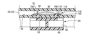
- the distal end portion of the rear support portion 34 b is deformed so as to approach the front side of the optical portion 30, but the distal end portion of the rear support portion 34 b is the optical portion 30. You may make it fold to the back side. Specifically, as shown in FIG. 9, the rear abutting protrusion 116 is projected from the bottom surface 114 of the rear collar (in the right direction in FIG.
- the abutting state of the rear support portion 34b to the rear contact protrusion 116 is such that the distal end portion of the rear support portion 34b of the intraocular lens 12 accommodated in the placement portion 14 enters the rear surface side of the optical unit 30 in advance. This can be easily realized by closing the cover member 42 in the bent state. In other words, after the cover member 42 is closed, the rear support portion 34b that gradually returns to the initial state comes into contact with the rear contact protrusion 116, and the deformed state is maintained.
- the front support portion 34a and the rear support portion 34b are brought into contact with the single contact protrusions 72, 74, and 116, respectively, toward the optical unit 30 side.
- a plurality of abutting protrusions may abut on a plurality of locations of the support portions 34a and 34b to be bent or curved in advance.
- the front support part 34 a and the rear support part 34 b of the intraocular lens 12 are in contact with the front contact protrusion 72 and the rear contact protrusions 74 and 116.
- the front support part 34a and the rear support part 34b do not necessarily need to be deformed toward the optical part 30 side, but are deformed to the optical part 30 side. You may make it deform
- the front support part 34 a may be deformed to the lower side (lower side in FIG. 7) in the optical axis direction of the optical part 30 without approaching the optical part 30.
- the front support portion 34a is controlled to be folded into the rear surface side of the optical portion 30 of the intraocular lens 12, so that the tucking state is achieved. May be realized.
- the rear support part 34b is located on the upper side in the optical axis direction of the optical part 30 without approaching the optical part 30. You may make it deform
- the rear support part 34 b is controlled to be deformed to the front side of the optical part 30 of the intraocular lens 12.
- the rear support 34b may be prevented from being folded. Further, the rear abutting protrusion 116 shown in FIG.
- the rear support part 34b is not moved closer to the optical part 30 and the lower side of the optical part 30 in the optical axis direction. You may make it deform
- an intraocular lens insertion device 122 as still another embodiment of the present invention will be described with reference to FIGS.
- the rear support portion 34 b of the intraocular lens 12 is replaced with a rear abutment protrusion 74 provided integrally with the holding member 54 with respect to the intraocular lens insertion device 10 of the first embodiment.
- the rear abutting protrusion 124 protruding from the mounting surface 38 can be held with high accuracy.
- the peripheral wall 64 on the holding projection 62 is divided into two, and the front part of the intraocular lens 12 and the vicinity of the optical part 30 of the rear support parts 34a and 34b are held between the peripheral walls 64a and 64b.
- the front support portion 34 a is disposed so as to contact the surface of the front contact protrusion 72 facing the optical unit 30. As a result, the front support portion 34a is bent or curved so as to approach the optical portion 30 side.
- the rear abutting protrusion 124 has a substantially cylindrical shape, and has a substantially cylindrical protrusion 126 having the same central axis and a small radius at the upper part thereof.
- the rear support portion 34 b is disposed so as to abut the surface of the protrusion 126 on the rear contact protrusion 124 facing the optical portion 30.
- the upper end surface of the rear abutting protrusion 124 provided with the protrusion 126 has substantially the same height as the upper surface of the optical part 30.
- the rear abutment protrusion 124 is placed on the placement surface 38 even when the intraocular lens 12 is pushed out by the rod-like portion 94 of the push member 22. Since it is arranged as it is, the rear support portion 34b can be more reliably deformed and placed on the optical unit 30 upper side.
- the introduction protrusion 92 extending in the axial direction of the device body 16 across the center portion in the width direction of the bottom surface 88 extends over substantially the entire length of the mounting surface 38. It extends.
- the intraocular lens 12 placed on the rod-like portion 94 of the pushing member 22, that is, the placement surface 38 can be accurately guided in the axial pushing direction.
- the bottom surface of the optical unit 30 is in contact with the upper portion of the introduction projection 92.
Landscapes
- Health & Medical Sciences (AREA)
- Ophthalmology & Optometry (AREA)
- Cardiology (AREA)
- Oral & Maxillofacial Surgery (AREA)
- Transplantation (AREA)
- Engineering & Computer Science (AREA)
- Biomedical Technology (AREA)
- Heart & Thoracic Surgery (AREA)
- Vascular Medicine (AREA)
- Life Sciences & Earth Sciences (AREA)
- Animal Behavior & Ethology (AREA)
- General Health & Medical Sciences (AREA)
- Public Health (AREA)
- Veterinary Medicine (AREA)
- Prostheses (AREA)
Abstract
Priority Applications (4)
| Application Number | Priority Date | Filing Date | Title |
|---|---|---|---|
| ES12832045T ES2725562T3 (es) | 2011-09-15 | 2012-09-13 | Herramienta de inserción de lente intraocular |
| US14/342,822 US9427314B2 (en) | 2011-09-15 | 2012-09-13 | Intraocular lens insertion tool |
| EP12832045.4A EP2756823B1 (fr) | 2011-09-15 | 2012-09-13 | Outil d'insertion de lentille intraoculaire |
| JP2013533515A JP6027535B2 (ja) | 2011-09-15 | 2012-09-13 | 眼内レンズの挿入器具 |
Applications Claiming Priority (2)
| Application Number | Priority Date | Filing Date | Title |
|---|---|---|---|
| JP2011201615 | 2011-09-15 | ||
| JP2011-201615 | 2011-09-15 |
Publications (1)
| Publication Number | Publication Date |
|---|---|
| WO2013038687A1 true WO2013038687A1 (fr) | 2013-03-21 |
Family
ID=47882936
Family Applications (1)
| Application Number | Title | Priority Date | Filing Date |
|---|---|---|---|
| PCT/JP2012/005859 Ceased WO2013038687A1 (fr) | 2011-09-15 | 2012-09-13 | Outil d'insertion de lentille intraoculaire |
Country Status (5)
| Country | Link |
|---|---|
| US (1) | US9427314B2 (fr) |
| EP (1) | EP2756823B1 (fr) |
| JP (1) | JP6027535B2 (fr) |
| ES (1) | ES2725562T3 (fr) |
| WO (1) | WO2013038687A1 (fr) |
Cited By (5)
| Publication number | Priority date | Publication date | Assignee | Title |
|---|---|---|---|---|
| WO2015125905A1 (fr) * | 2014-02-20 | 2015-08-27 | 参天製薬株式会社 | Injecteur pour lentille intra-oculaire |
| WO2016013563A1 (fr) * | 2014-07-22 | 2016-01-28 | 興和株式会社 | Outil d'insertion de lentille intraoculaire |
| JP2016019604A (ja) * | 2014-07-14 | 2016-02-04 | 株式会社ニデック | 眼内レンズ挿入器具及び眼内レンズ挿入システム |
| JP2016019605A (ja) * | 2014-07-14 | 2016-02-04 | 株式会社ニデック | 眼内レンズ挿入器具及び眼内レンズ挿入システム |
| JP2016087336A (ja) * | 2014-11-11 | 2016-05-23 | 株式会社ニデック | 眼内レンズ挿入器具 |
Families Citing this family (5)
| Publication number | Priority date | Publication date | Assignee | Title |
|---|---|---|---|---|
| US10588780B2 (en) | 2015-03-04 | 2020-03-17 | Alcon Inc. | Intraocular lens injector |
| US10568735B2 (en) | 2017-01-13 | 2020-02-25 | Alcon Inc. | Intraocular lens injector |
| US11000367B2 (en) | 2017-01-13 | 2021-05-11 | Alcon Inc. | Intraocular lens injector |
| CN113827372B (zh) * | 2020-06-08 | 2024-08-23 | 富螺(上海)医疗器械有限公司 | 人工晶体保存盒以及人工晶体的植入方法 |
| US20230225859A1 (en) * | 2022-01-19 | 2023-07-20 | Beaver-Visitec International, Inc. | Intraocular lens delivery system |
Citations (6)
| Publication number | Priority date | Publication date | Assignee | Title |
|---|---|---|---|---|
| JP3641110B2 (ja) | 1997-08-20 | 2005-04-20 | 株式会社メニコン | 軟質眼内レンズ用材料 |
| JP2006181269A (ja) | 2004-12-28 | 2006-07-13 | Hoya Corp | 眼内レンズ挿入用器具 |
| WO2008029498A1 (fr) * | 2006-09-05 | 2008-03-13 | Kowa Company, Ltd. | Instrument d'insertion de lentille intraoculaire |
| JP2009160138A (ja) * | 2007-12-28 | 2009-07-23 | Menicon Co Ltd | 眼内レンズの挿入器具 |
| JP2009291399A (ja) | 2008-06-05 | 2009-12-17 | Hoya Corp | 眼内レンズ挿入器具及びカートリッジ |
| WO2011048631A1 (fr) * | 2009-10-22 | 2011-04-28 | 株式会社メニコン | Dispositif d'insertion de cristallin artificiel |
Family Cites Families (17)
| Publication number | Priority date | Publication date | Assignee | Title |
|---|---|---|---|---|
| US6406481B2 (en) | 1992-09-30 | 2002-06-18 | Starr Surgical Company, Inc. | Method preloading a deformable intraocular lens into injecting apparatus for storage and/or shipment |
| JP3944555B2 (ja) * | 1999-10-06 | 2007-07-11 | キヤノンスター株式会社 | 眼内挿入用レンズの挿入システム |
| US6387101B1 (en) | 1999-10-22 | 2002-05-14 | Staar Surgical Company, Inc. | Deformable intraocular lens injecting apparatus and method |
| SE9904338D0 (sv) | 1999-11-30 | 1999-11-30 | Pharmacia & Upjohn Ab | Intraocular lens implanter |
| WO2002096322A1 (fr) * | 2001-05-25 | 2002-12-05 | Hoya Healthcare Corporation | Recipient de stockage ayant une fonction de pliage de lentilles intraoculaires souples |
| US6537283B2 (en) | 2001-08-17 | 2003-03-25 | Alcon, Inc. | Intraocular lens shipping case and injection cartridge |
| FR2833154B1 (fr) * | 2001-12-12 | 2004-11-19 | Ioltechnologie Production | Cassette et injecteur de lentille intraoculaire souple et procede d'injection de telles lentilles |
| US7156854B2 (en) * | 2003-05-28 | 2007-01-02 | Alcon, Inc. | Lens delivery system |
| AU2007208009B2 (en) * | 2006-01-26 | 2013-05-16 | Johnson & Johnson Surgical Vision, Inc. | Intraocular lens insertion apparatus and lens case |
| US8679573B2 (en) | 2006-06-28 | 2014-03-25 | Advanced Cardiovascular Systems, Inc. | Stent coating method and apparatus |
| JP4927473B2 (ja) * | 2006-08-11 | 2012-05-09 | 興和株式会社 | 眼内レンズの挿入器具 |
| JP5255832B2 (ja) * | 2007-12-28 | 2013-08-07 | 興和株式会社 | 眼内レンズの挿入器具 |
| US8273122B2 (en) | 2008-06-23 | 2012-09-25 | Abbott Medical Optics Inc. | Pre-loaded IOL insertion system |
| WO2010064275A1 (fr) * | 2008-12-01 | 2010-06-10 | 株式会社メニコン | Outil d'insertion pour une lentille intraoculaire |
| AU2010213941B2 (en) | 2009-02-11 | 2014-02-20 | Alcon Inc. | Automated intraocular lens injector device |
| GB2472873A (en) | 2009-08-18 | 2011-02-23 | Carl Zeiss Meditec Sas | Cassette for intraocular lens |
| EP2502603B1 (fr) | 2009-11-17 | 2016-10-19 | Kowa Company Ltd. | Dispositif d'insertion de lentille intraoculaire |
-
2012
- 2012-09-13 JP JP2013533515A patent/JP6027535B2/ja not_active Expired - Fee Related
- 2012-09-13 EP EP12832045.4A patent/EP2756823B1/fr not_active Revoked
- 2012-09-13 US US14/342,822 patent/US9427314B2/en not_active Expired - Fee Related
- 2012-09-13 ES ES12832045T patent/ES2725562T3/es active Active
- 2012-09-13 WO PCT/JP2012/005859 patent/WO2013038687A1/fr not_active Ceased
Patent Citations (6)
| Publication number | Priority date | Publication date | Assignee | Title |
|---|---|---|---|---|
| JP3641110B2 (ja) | 1997-08-20 | 2005-04-20 | 株式会社メニコン | 軟質眼内レンズ用材料 |
| JP2006181269A (ja) | 2004-12-28 | 2006-07-13 | Hoya Corp | 眼内レンズ挿入用器具 |
| WO2008029498A1 (fr) * | 2006-09-05 | 2008-03-13 | Kowa Company, Ltd. | Instrument d'insertion de lentille intraoculaire |
| JP2009160138A (ja) * | 2007-12-28 | 2009-07-23 | Menicon Co Ltd | 眼内レンズの挿入器具 |
| JP2009291399A (ja) | 2008-06-05 | 2009-12-17 | Hoya Corp | 眼内レンズ挿入器具及びカートリッジ |
| WO2011048631A1 (fr) * | 2009-10-22 | 2011-04-28 | 株式会社メニコン | Dispositif d'insertion de cristallin artificiel |
Non-Patent Citations (1)
| Title |
|---|
| See also references of EP2756823A4 * |
Cited By (10)
| Publication number | Priority date | Publication date | Assignee | Title |
|---|---|---|---|---|
| WO2015125905A1 (fr) * | 2014-02-20 | 2015-08-27 | 参天製薬株式会社 | Injecteur pour lentille intra-oculaire |
| CN106029007A (zh) * | 2014-02-20 | 2016-10-12 | 参天制药株式会社 | 眼内透镜用注射器 |
| CN106029007B (zh) * | 2014-02-20 | 2018-01-30 | 参天制药株式会社 | 眼内透镜用注射器 |
| US10206815B2 (en) | 2014-02-20 | 2019-02-19 | Santen Pharmaceutical Co., Ltd | Injector for intraocular lens |
| JP2016019604A (ja) * | 2014-07-14 | 2016-02-04 | 株式会社ニデック | 眼内レンズ挿入器具及び眼内レンズ挿入システム |
| JP2016019605A (ja) * | 2014-07-14 | 2016-02-04 | 株式会社ニデック | 眼内レンズ挿入器具及び眼内レンズ挿入システム |
| EP2974697A3 (fr) * | 2014-07-14 | 2016-04-27 | Nidek Co., Ltd | Dispositif d'insertion de lentille intraoculaire |
| WO2016013563A1 (fr) * | 2014-07-22 | 2016-01-28 | 興和株式会社 | Outil d'insertion de lentille intraoculaire |
| JPWO2016013563A1 (ja) * | 2014-07-22 | 2017-04-27 | 興和株式会社 | 眼内レンズの挿入器具 |
| JP2016087336A (ja) * | 2014-11-11 | 2016-05-23 | 株式会社ニデック | 眼内レンズ挿入器具 |
Also Published As
| Publication number | Publication date |
|---|---|
| US20140228856A1 (en) | 2014-08-14 |
| JP6027535B2 (ja) | 2016-11-16 |
| US9427314B2 (en) | 2016-08-30 |
| ES2725562T3 (es) | 2019-09-24 |
| EP2756823A1 (fr) | 2014-07-23 |
| EP2756823A4 (fr) | 2015-08-05 |
| JPWO2013038687A1 (ja) | 2015-03-23 |
| EP2756823B1 (fr) | 2019-02-13 |
Similar Documents
| Publication | Publication Date | Title |
|---|---|---|
| JP6027535B2 (ja) | 眼内レンズの挿入器具 | |
| JP4908977B2 (ja) | 眼内レンズの挿入器具 | |
| US6858033B2 (en) | Insertion system for intraocular lens | |
| JP5412526B2 (ja) | 眼内レンズ挿入器具 | |
| CN105473104B (zh) | 用于容置眼内透镜的装置 | |
| JP5391332B2 (ja) | 眼内レンズカートリッジ | |
| US20030212407A1 (en) | Insertion system for intraocular lens | |
| EP2343029B1 (fr) | Instrument d'injection de lentille intraoculaire | |
| JP2001104347A (ja) | 眼内挿入用レンズの挿入システム | |
| JP2009018009A (ja) | 眼内レンズ挿入器具及び眼内レンズの移動制御方法 | |
| JPWO2011048631A1 (ja) | 眼内レンズ挿入器具 | |
| WO2009154187A1 (fr) | Instrument pour l’insertion de lentille intraoculaire | |
| JP3665463B2 (ja) | 変形可能な眼内挿入用レンズの挿入器具 | |
| JP5874351B2 (ja) | 眼内レンズ挿入システム | |
| JP6027536B2 (ja) | 眼内レンズの挿入器具 | |
| JP5980218B2 (ja) | 眼内レンズの挿入器具 | |
| EP3682850A1 (fr) | Instrument d'insertion d'une lentille intraoculaire | |
| JP7021477B2 (ja) | 眼内レンズ挿入器具 | |
| JP7613199B2 (ja) | 眼内レンズ挿入器具 | |
| JP2004290690A (ja) | 眼内挿入用レンズの挿入器具 | |
| JP5096132B2 (ja) | 眼内レンズの挿入器具 | |
| JP2004344478A (ja) | 眼内挿入用レンズの挿入システム | |
| JP2019170928A (ja) | 眼内レンズ挿入器具 | |
| HK40027078A (en) | Intraocular lens insertion instrument | |
| JP2005246104A (ja) | 眼内挿入用レンズの挿入器具 |
Legal Events
| Date | Code | Title | Description |
|---|---|---|---|
| 121 | Ep: the epo has been informed by wipo that ep was designated in this application |
Ref document number: 12832045 Country of ref document: EP Kind code of ref document: A1 |
|
| ENP | Entry into the national phase |
Ref document number: 2013533515 Country of ref document: JP Kind code of ref document: A |
|
| WWE | Wipo information: entry into national phase |
Ref document number: 14342822 Country of ref document: US |
|
| NENP | Non-entry into the national phase |
Ref country code: DE |
|
| WWE | Wipo information: entry into national phase |
Ref document number: 2012832045 Country of ref document: EP |