WO2013042490A1 - 発電電動機とこれを用いた電動車両 - Google Patents
発電電動機とこれを用いた電動車両 Download PDFInfo
- Publication number
- WO2013042490A1 WO2013042490A1 PCT/JP2012/070636 JP2012070636W WO2013042490A1 WO 2013042490 A1 WO2013042490 A1 WO 2013042490A1 JP 2012070636 W JP2012070636 W JP 2012070636W WO 2013042490 A1 WO2013042490 A1 WO 2013042490A1
- Authority
- WO
- WIPO (PCT)
- Prior art keywords
- generator motor
- bracket
- shaft
- oil
- injection holes
- Prior art date
- Legal status (The legal status is an assumption and is not a legal conclusion. Google has not performed a legal analysis and makes no representation as to the accuracy of the status listed.)
- Ceased
Links
Images




Classifications
-
- H—ELECTRICITY
- H02—GENERATION; CONVERSION OR DISTRIBUTION OF ELECTRIC POWER
- H02K—DYNAMO-ELECTRIC MACHINES
- H02K9/00—Arrangements for cooling or ventilating
- H02K9/19—Arrangements for cooling or ventilating for machines with closed casing and closed-circuit cooling using a liquid cooling medium, e.g. oil
- H02K9/193—Arrangements for cooling or ventilating for machines with closed casing and closed-circuit cooling using a liquid cooling medium, e.g. oil with provision for replenishing the cooling medium; with means for preventing leakage of the cooling medium
-
- H—ELECTRICITY
- H02—GENERATION; CONVERSION OR DISTRIBUTION OF ELECTRIC POWER
- H02K—DYNAMO-ELECTRIC MACHINES
- H02K9/00—Arrangements for cooling or ventilating
- H02K9/19—Arrangements for cooling or ventilating for machines with closed casing and closed-circuit cooling using a liquid cooling medium, e.g. oil
-
- H—ELECTRICITY
- H02—GENERATION; CONVERSION OR DISTRIBUTION OF ELECTRIC POWER
- H02K—DYNAMO-ELECTRIC MACHINES
- H02K3/00—Details of windings
- H02K3/04—Windings characterised by the conductor shape, form or construction, e.g. with bar conductors
- H02K3/24—Windings characterised by the conductor shape, form or construction, e.g. with bar conductors with channels or ducts for cooling medium between the conductors
-
- H—ELECTRICITY
- H02—GENERATION; CONVERSION OR DISTRIBUTION OF ELECTRIC POWER
- H02K—DYNAMO-ELECTRIC MACHINES
- H02K5/00—Casings; Enclosures; Supports
- H02K5/04—Casings or enclosures characterised by the shape, form or construction thereof
- H02K5/16—Means for supporting bearings, e.g. insulating supports or means for fitting bearings in the bearing-shields
- H02K5/161—Means for supporting bearings, e.g. insulating supports or means for fitting bearings in the bearing-shields radially supporting the rotary shaft at both ends of the rotor
-
- H—ELECTRICITY
- H02—GENERATION; CONVERSION OR DISTRIBUTION OF ELECTRIC POWER
- H02K—DYNAMO-ELECTRIC MACHINES
- H02K5/00—Casings; Enclosures; Supports
- H02K5/04—Casings or enclosures characterised by the shape, form or construction thereof
- H02K5/20—Casings or enclosures characterised by the shape, form or construction thereof with channels or ducts for flow of cooling medium
- H02K5/203—Casings or enclosures characterised by the shape, form or construction thereof with channels or ducts for flow of cooling medium specially adapted for liquids, e.g. cooling jackets
-
- H—ELECTRICITY
- H02—GENERATION; CONVERSION OR DISTRIBUTION OF ELECTRIC POWER
- H02K—DYNAMO-ELECTRIC MACHINES
- H02K9/00—Arrangements for cooling or ventilating
- H02K9/19—Arrangements for cooling or ventilating for machines with closed casing and closed-circuit cooling using a liquid cooling medium, e.g. oil
- H02K9/20—Arrangements for cooling or ventilating for machines with closed casing and closed-circuit cooling using a liquid cooling medium, e.g. oil wherein the cooling medium vaporises within the machine casing
-
- B—PERFORMING OPERATIONS; TRANSPORTING
- B60—VEHICLES IN GENERAL
- B60K—ARRANGEMENT OR MOUNTING OF PROPULSION UNITS OR OF TRANSMISSIONS IN VEHICLES; ARRANGEMENT OR MOUNTING OF PLURAL DIVERSE PRIME-MOVERS IN VEHICLES; AUXILIARY DRIVES FOR VEHICLES; INSTRUMENTATION OR DASHBOARDS FOR VEHICLES; ARRANGEMENTS IN CONNECTION WITH COOLING, AIR INTAKE, GAS EXHAUST OR FUEL SUPPLY OF PROPULSION UNITS IN VEHICLES
- B60K1/00—Arrangement or mounting of electrical propulsion units
- B60K2001/003—Arrangement or mounting of electrical propulsion units with means for cooling the electrical propulsion units
- B60K2001/006—Arrangement or mounting of electrical propulsion units with means for cooling the electrical propulsion units the electric motors
-
- B—PERFORMING OPERATIONS; TRANSPORTING
- B60—VEHICLES IN GENERAL
- B60L—PROPULSION OF ELECTRICALLY-PROPELLED VEHICLES; SUPPLYING ELECTRIC POWER FOR AUXILIARY EQUIPMENT OF ELECTRICALLY-PROPELLED VEHICLES; ELECTRODYNAMIC BRAKE SYSTEMS FOR VEHICLES IN GENERAL; MAGNETIC SUSPENSION OR LEVITATION FOR VEHICLES; MONITORING OPERATING VARIABLES OF ELECTRICALLY-PROPELLED VEHICLES; ELECTRIC SAFETY DEVICES FOR ELECTRICALLY-PROPELLED VEHICLES
- B60L2200/00—Type of vehicles
-
- B—PERFORMING OPERATIONS; TRANSPORTING
- B60—VEHICLES IN GENERAL
- B60L—PROPULSION OF ELECTRICALLY-PROPELLED VEHICLES; SUPPLYING ELECTRIC POWER FOR AUXILIARY EQUIPMENT OF ELECTRICALLY-PROPELLED VEHICLES; ELECTRODYNAMIC BRAKE SYSTEMS FOR VEHICLES IN GENERAL; MAGNETIC SUSPENSION OR LEVITATION FOR VEHICLES; MONITORING OPERATING VARIABLES OF ELECTRICALLY-PROPELLED VEHICLES; ELECTRIC SAFETY DEVICES FOR ELECTRICALLY-PROPELLED VEHICLES
- B60L2200/00—Type of vehicles
- B60L2200/40—Working vehicles
-
- H—ELECTRICITY
- H02—GENERATION; CONVERSION OR DISTRIBUTION OF ELECTRIC POWER
- H02K—DYNAMO-ELECTRIC MACHINES
- H02K9/00—Arrangements for cooling or ventilating
-
- Y—GENERAL TAGGING OF NEW TECHNOLOGICAL DEVELOPMENTS; GENERAL TAGGING OF CROSS-SECTIONAL TECHNOLOGIES SPANNING OVER SEVERAL SECTIONS OF THE IPC; TECHNICAL SUBJECTS COVERED BY FORMER USPC CROSS-REFERENCE ART COLLECTIONS [XRACs] AND DIGESTS
- Y02—TECHNOLOGIES OR APPLICATIONS FOR MITIGATION OR ADAPTATION AGAINST CLIMATE CHANGE
- Y02T—CLIMATE CHANGE MITIGATION TECHNOLOGIES RELATED TO TRANSPORTATION
- Y02T10/00—Road transport of goods or passengers
- Y02T10/60—Other road transportation technologies with climate change mitigation effect
- Y02T10/64—Electric machine technologies in electromobility
-
- Y—GENERAL TAGGING OF NEW TECHNOLOGICAL DEVELOPMENTS; GENERAL TAGGING OF CROSS-SECTIONAL TECHNOLOGIES SPANNING OVER SEVERAL SECTIONS OF THE IPC; TECHNICAL SUBJECTS COVERED BY FORMER USPC CROSS-REFERENCE ART COLLECTIONS [XRACs] AND DIGESTS
- Y02—TECHNOLOGIES OR APPLICATIONS FOR MITIGATION OR ADAPTATION AGAINST CLIMATE CHANGE
- Y02T—CLIMATE CHANGE MITIGATION TECHNOLOGIES RELATED TO TRANSPORTATION
- Y02T90/00—Enabling technologies or technologies with a potential or indirect contribution to GHG emissions mitigation
- Y02T90/10—Technologies relating to charging of electric vehicles
- Y02T90/16—Information or communication technologies improving the operation of electric vehicles
Definitions
- the present invention relates to a generator motor including a permanent magnet for a field in a rotor, and more particularly to a permanent magnet generator motor for an electric vehicle driven in a high temperature environment.
- Permanent magnet type rotating electrical machines have been improved in performance with the development of high residual magnetic flux density magnets, and are used in all aspects.
- high energy efficiency is demanded for motors for industrial use and home appliances, and the application ratio of permanent magnet type motors tends to be extremely high.
- Patent Document 1 proposes a conventional structure for directly oil-cooling the generator motor.
- the cooling oil forcedly circulated is configured to be injected between the slot central portion, that is, between the motor windings, through an oil passage provided in a bracket that holds the motor. The winding is cooling along.
- An object of the present invention is to provide a cooling structure that achieves densification, and in particular, cools the armature winding in a well-balanced manner in the circumferential direction of the stator of the generator motor.
- the present invention mainly adopts the following configuration.
- the bracket provided with the bearing interposed therebetween includes a passage through which a cooling medium flows, and a winding end portion of the armature winding in communication with the passage.
- An injection hole for injecting the cooling medium at a position opposed to the shaft, and from the injection hole of the bracket arranged on both sides in the axial direction of the shaft toward the winding end of the armature winding The cooling medium is ejected, and the flow rate distribution of the cooling medium from the plurality of injection holes is set to be higher as the position becomes higher than the height position of the shaft.
- the pitch of the injection holes provided in the bracket is dense at the upper part in the vertical direction of the bracket, and gradually becomes sparse as the height of the shaft is reached.
- the diameter of the injection hole provided in the bracket is large at the upper part in the vertical direction of the bracket, and gradually becomes smaller as the height of the shaft is reached.
- the number of injection holes provided at positions facing the winding ends of the armature winding is large at the upper part in the vertical direction of the bracket, and gradually decreases as the height of the shaft is reached.
- the generator motor an engine having an internal combustion engine connected to the shaft of the generator motor, and a hydraulic pump having a hydraulic mechanism connected to the shaft of the generator motor and installed on the opposite side of the engine. Electric vehicle equipped.
- the armature winding of the generator motor can be cooled with good balance over the circumferential direction of the stator, and the cooling effect can be enhanced.
- the cooling effect required under the condition of being placed in a small space in a high temperature environment can be further enhanced and contribute to miniaturization and high output density. it can.
- FIG. 2 is a cross-sectional view in the direction perpendicular to the axis of a housing and an auxiliary oil sump in the generator motor according to the first embodiment, and is a cross-sectional view taken along the line A-A ′ in FIG. 1.
- FIG. 10 is a cross-sectional view in the direction perpendicular to the axis of a housing and a cooling water channel in a generator motor according to a fifth embodiment, and is a cross-sectional view taken along the line B-B ′ of FIG. 10.
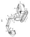
- FIG. 10 is sectional drawing of the axial direction which shows the structure of the auxiliary oil sump part in the generator motor which concerns on the 6th Example of this invention. It is a sketch which shows the external appearance of the hydraulic shovel to which the generator motor which concerns on the 7th Example of this invention is applied.
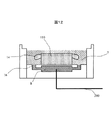
- FIG. 1 is an axial sectional view showing the overall configuration of a generator motor according to a first embodiment of the present invention.
- FIG. 2 is an exploded view showing an oil passage in the bracket in the generator motor according to the first embodiment.
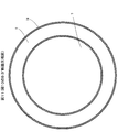
- FIG. 3 is a sectional view showing the relationship between the armature winding and the position of the oil injection hole in the generator motor according to the first embodiment.
- 4 is a cross-sectional view of the housing and the auxiliary oil sump portion in the direction perpendicular to the axis in the generator motor according to the first embodiment, and is a cross-sectional view taken along the line A-A 'of FIG.
- FIG. 5 is a diagram showing the measurement result of the temperature distribution of the armature winding in the generator motor according to the first embodiment.
- the rotor 130 is configured by arranging a plurality of magnet insertion holes 132 and permanent magnets 133 provided inside the rotor core 131 provided on the shaft 6.
- the permanent magnet 133 is a flat sintered magnet whose main component is a rare earth.
- bearings 5A and 5B are fixed to the bracket 200 (consisting of 200A and 200B), the shaft 6 is rotatably supported by the bearings 5A and 5B, and the rotor 130 is rotatable by the bearings 5A and 5B. Supported.
- the stator 1 is provided with a large number of stator slots 111 provided in the stator core 110 (12 in this embodiment).
- armature windings 14 corresponding to the phases of the U-phase coil, V-phase coil, and W-phase coil are embedded, and a plurality of insulated copper wires (not shown) are bundled.
- One coil is formed in a shape, and this coil is wound at least one turn.
- the armature winding 14 is wound in a concentrated winding so as to surround the tooth 112 adjacent to the slot 111, and a magnetic pole piece 113 is provided at the inner peripheral end of the tooth 112 to prevent the winding from dropping off.
- a slot opening 114 is provided between the magnetic pole pieces 113, and an armature winding 14 is formed by inserting a copper wire from the slot 114.
- the stator 1 is fixed to the inner peripheral side of the cylindrical housing 18 by shrink fitting or press fitting.
- the housing 18 has an auxiliary oil sump portion 8 (consisting of 8A and 8B) communicating with the main oil sump portion 7 through a pore 16 provided in the center portion on the outer peripheral side of the stator core 110 and Two locations are provided on the outside in the axial direction, and are filled with the cooling oil 10.
- the oil level of the cooling oil 10 is in contact with the outer diameter of the rotor 130, but the oil level can also be configured below that.
- the bracket 200 is provided with an oil passage groove 202 concentrically provided in communication with an oil passage 201 provided at an upper portion in the vertical direction.
- a ring 203 provided with an oil injection hole 204 is fixed so as to cover the oil passage groove 202.
- the oil injection holes 204 provided in the ring 203 are arranged at the same pitch as the teeth 112 and are provided so as to face the armature winding 14 (more specifically, the winding end: coil end).
- the bracket 200 is configured to be dense (5 in the present embodiment) at the upper part in the vertical direction and sparse (0 in the present embodiment) in the horizontal direction.
- the oil ejection hole 204 is not limited to the ring 203 and may be provided in the bracket 200. Further, not limited to the example of FIG.
- an injection hole 204 is provided for each winding end portion in the upper part in the vertical direction, and two lower end portions.
- the injection hole 204 may be provided for each winding end, and the injection hole 204 may be provided for every three winding ends at the same level as the shaft 6.
- the flow rate distribution of the cooling oil that ejects the cooling oil 10 from the plurality of injection holes 204 from the brackets 200 ⁇ / b> A and 200 ⁇ / b> B on both sides toward the winding end of the armature winding 14 is higher than the height position of the shaft 6. Is set higher as the position becomes higher.
- this setting method is defined by the number of injection holes 204. The above-described method for setting the flow distribution of the cooling oil is common to the other embodiments.
- the oil ejection holes 204 are not provided in the lower portion of the ring 203 in addition to the horizontal portion of the ring 203.
- the armature windings corresponding to the horizontal portion and the lower portion of the ring 203 are cooled by cooling oil injected from the oil injection holes 204 in the upper portion.
- the oil pipe 300 connects the auxiliary oil reservoirs 8A and 8B and the oil pump 301, the oil pump 301 and the oil cooler 302, and the oil cooler 302 and the oil passage 201 provided in the bracket 200, respectively. ing.
- the cooling oil 10 stored in the auxiliary oil reservoirs 8A and 8B can be circulated to the oil passages 201A and 202B after being pumped by the oil pump 301 and cooled by the oil cooler 302.
- the oil passages 201A and 201B communicate with the oil injection holes 204A and 204B provided in the oil passage grooves 202A and 202B and the rings 203A and 203B, the oil passages 201A and 201B are injected into the armature winding 14 from both sides in the axial direction. Can be made.
- FIG. 5 is a diagram showing the measurement result of the temperature distribution of the armature winding in the generator motor according to the first embodiment.
- FIG. 5 illustrates the temperature distribution of the present example in comparison with the temperature distribution of the comparative example, and shows the normalized temperature as 100% in the cooling method of the comparative example.
- the cooling method of the comparative example is a case where the injection holes 204 provided in the ring 203 are arranged on the entire circumference at equal intervals.
- the difference in temperature distribution in the armature winding is about 90% at the maximum. 200) (corresponding to the top in the vertical direction of 200) and 90 ° and 270 ° (corresponding to the horizontal direction of the bracket 200).
- the pressure distribution in the oil injection holes 204 is different from that of the present embodiment in which the injection holes are provided only in the upper part.
- the difference in the temperature distribution in the circumferential direction is greatly reduced, resulting in a substantially uniform temperature distribution.
- the reason for this will be described.
- the injection holes 204 provided in the ring 203 are provided at equal pitches with the teeth 112 and so as to face the armature winding 14, and are dense in the vertical upper part of the bracket 200 and sparse in the horizontal direction. Therefore, the cooling oil can be injected intensively and in a large amount directly on the armature winding 14 in the upper vertical direction (directly cooling the coil end that is a heating element). The temperature near 0 ° at the circumferential position can be reduced.
- the injection holes 204 are not provided in the horizontal direction (around 90 ° and 270 ° in the circumferential direction), the cooling is performed only with the cooling oil flowing down from the upper part in the vertical direction. As a result, the circumferential direction is uniform. Cooling is done.
- the ring 203 is arranged on both sides in the axial direction (refer to the oil injection holes 204A and 204B arranged on the left and right sides shown in FIG. 1), the effect described above can be similarly obtained on both sides in the axial direction. Needless to say.
- the flow rate of the cooling oil to be injected is increased in the upper part but small in the side part, so that the overall flow rate can be suppressed to the minimum, so that the power of the oil pump 301 can be reduced, There is merit that can contribute to energy saving of drive system.
- the circulating cooling oil 10 is pumped from the auxiliary oil reservoir 8.
- the oil sump for storing the cooling oil 10 is composed of a main oil sump 7 and an auxiliary oil sump 8 communicated by the pores 16, and the oil pipe 300 is inserted into the auxiliary oil sump 8. Therefore, even if the electric construction machine (not shown) works on an inclined ground and the oil level of the main oil sump 7 is inclined, the cooling oil 10 can be circulated stably.
- an auxiliary oil sump is provided so that cooling oil can be circulated even when a hydraulic excavator or wheel loader (hereinafter referred to as a hydraulic excavator) equipped with the generator motor according to the present embodiment is tilted back and forth and left and right.
- a pore 16 (small-diameter passage) is provided in the central portion of the portion 8. Providing the pores 16 prevents air from entering the auxiliary oil reservoir 8 even if the excavator is inclined. In other words, the pores 16 are provided at heights and positions so that air does not enter the auxiliary oil reservoir 8 even when the generator motor is inclined.
- the generator motor 50 includes a limited narrow space between the engine 51 including the internal combustion engine section 512 and the flywheel 511, and the hydraulic pump 52 formed by the gear 521 and the hydraulic mechanism section 522. It is installed in a space, and functions as an electric motor that assists the power necessary for driving the hydraulic pump 52 together with the engine 51, and converts the mechanical output of the engine 51 into an electrical output, It functions as a generator that covers power supply to electrical equipment (not shown).
- the generator-motor configuration shown in FIGS. 1 to 5 enables the armature winding wound around the stator to be cooled in a balanced manner in the circumferential direction of the stator, and has a high cooling effect.
- An electric motor cooling configuration can be provided.
- FIG. 6 is a cross-sectional view showing the relationship between the armature winding and the hole diameter of the oil injection hole in the generator motor according to the second embodiment.
- FIG. 6 the same components as those in FIG.
- the second embodiment is different from the first embodiment shown in FIG. 3 in that the diameter of the oil injection hole 204 provided in the ring 203 is large in the upper part in the vertical direction, small in the horizontal direction, and small in the lower part in the vertical direction. It is in the point provided in the perimeter.
- the second embodiment is an example in which the hole diameter of the injection hole 204 provided in the bracket 200 is increased at the upper part in the vertical direction of the bracket 200 and gradually decreased as the height position of the shaft 6 is reached.
- small holes are provided in the horizontal and vertical lower portions of the ring 203, and by cooling with oil from these small holes and cooling with cooling oil flowing down from the upper portion in the vertical direction, A cooling effect equivalent to that of the armature winding 14 facing the coil is obtained.
- no small hole is provided in the lowermost part of the ring 203, but the configuration shown in FIG. 6 belongs to the scope of the technical idea of providing oil injection holes having different hole diameters on the entire circumference in this embodiment. .
- FIG. 7 is a cross-sectional view showing the relationship between the armature windings, the number of oil injection holes and the hole diameter in the generator motor according to the third embodiment.
- FIG. 7 the same components as those in FIG. 7
- the third embodiment is different from the first embodiment shown in FIG. 3 in that the number of oil injection holes 204 provided in the ring 203 is large in the upper part in the vertical direction and is reduced in the horizontal direction.
- the hole 204 has a hole diameter that is large in the upper part in the vertical direction and small in the horizontal direction.
- the diameter of the injection holes when the number of injection holes is large, the diameter of the injection holes is increased, and when the number of injection holes is small, the diameter of the injection holes is decreased.
- the number of injection holes provided at the position facing the winding end of the armature winding is increased at the upper part in the vertical direction of the bracket, and the height of the shaft is increased.
- a configuration example that gradually decreases may be used.
- FIG. 8 is an exploded view showing an oil passage in the bracket of the generator motor according to the fourth embodiment of the present invention
- FIG. 9 is an axial sectional view showing the entire configuration of the generator motor according to the fourth embodiment. It is. 8 and FIG. 9, the same components as those shown in FIG. 1 and FIG.
- the fourth embodiment shown in FIGS. 8 and 9 is different from the first embodiment shown in FIGS. 1 and 2 in that the oil passage groove 202 provided in the bracket 200 and the ring 203 are horizontally arranged from the upper part in the vertical direction. In addition, it is configured to have an arc shape in the direction, and in addition, the oil level of the cooling oil 10 stored in the main oil sump 7 is set to the inner diameter of the stator 1 (see FIG. 9). is there.
- the cooling effect of the armature winding 14 in the upper part in the vertical direction can be obtained in the same manner as in FIGS.
- the cooling in the lower part in the vertical direction is configured by cooling with the oil in the main oil sump 7 and the oil flowing down from above, so that the circulating pressure of the oil pump 301 can be further reduced. This can be further reduced.
- FIG. 10 is a sectional view in the axial direction showing the cooling water channel in the housing of the generator motor according to the fifth embodiment of the present invention
- FIG. 11 shows the shaft of the housing and the cooling water channel in the generator motor according to the fifth embodiment.
- 11 is a cross-sectional view in the vertical direction, and is a cross-sectional view taken along the line BB ′ in FIG. 10 and 11, the same components as those in FIG.
- the fifth embodiment is different from the first embodiment shown in FIG. 1 in that the cooling water passage 9 is provided in the housing 18.
- the cooling water passage 9 forms an annular path in the circumferential direction of the housing 18, and water is circulated by the external water pump 401, and water is cooled by the water cooler 402 to form a circulation path. .
- the cooling water channel 9 in the fifth embodiment is arranged on the outer diameter side of the stator core 110, the iron loss generated in the stator core 110 can be cooled and also generated in the armature winding 14. Copper loss can also be indirectly cooled through the stator core 110.
- the bottom of the housing 18 can contribute to cooling of the cooling oil 10 stored in the auxiliary oil reservoir 8.
- cooling water in the cooling water passage 9 can indirectly cool the stator 1 and the cooling oil 10
- energy saving of the drive system can be achieved by improving the efficiency of the generator motor and further reducing the flow rate of the cooling oil circulating in the oil pump 301.
- the oil cooler 302 can be reduced in size and eliminated, which contributes to a reduction in the size of the system and an increase in reliability associated with a reduction in the number of parts.
- FIG. 12 is a sectional view in the axial direction showing the structure of the auxiliary oil sump in the generator motor according to the sixth embodiment of the present invention.
- FIG. 12 the same components as those in FIG.
- the sixth embodiment of the present invention differs from the first embodiment shown in FIG. 1 in that the auxiliary oil sump 8 provided at the bottom of the housing 18 has a single structure.
- the influence of the oil level change of the cooling oil can be further reduced, and the stable cooling oil can be obtained.
- the number of branches of the oil pipe 300 can be reduced, which can contribute to the simplification of the oil pipe 300 and the improvement of reliability associated with the reduction of the connection places.
- FIG. 13 is a schematic diagram showing an external appearance of a hydraulic excavator to which the generator motor according to the seventh embodiment is applied
- FIG. 14 illustrates a situation in which the hydraulic excavator to which the generator motor according to the seventh embodiment is applied works on an inclined ground
- FIG. 15 is a cross-sectional configuration diagram of an engine chamber in a hydraulic excavator to which the generator motor according to the seventh embodiment is applied.
- the hydraulic excavator is provided on a traveling body 41, a revolving body 42 that is turnably provided on the traveling body 41, a cab 43 provided on the front left side of the revolving body 42, and the revolving body 42.
- An articulated front device 46 comprising a boom 461, an arm 462, and a bucket 463 provided at the front of the revolving body 42, an engine chamber 44 disposed horizontally, a counterweight 45 provided at the rear of the revolving body 42, and the revolving body 42. And is composed of.
- the traveling body 41 includes an endless track crawler 411 on the left and right, and is driven by the driving force of the traveling motor 412.
- the turning body 42 including the engine chamber 44 and the articulated front device 46 is turned with respect to the traveling body 41 by a turning motor (not shown) provided at the center of the turning body 42.
- the boom 461, the arm 462, and the bucket 463 that constitute the multi-joint type front device 46 are driven by a boom cylinder, an arm cylinder, and a bucket cylinder 47 that are provided respectively.
- the various cylinders 47, the traveling motor 412, and the turning motor described above use hydraulic actuators and are operated by the engine 51 and / or the generator motor 50 in the engine compartment 44 in response to an operation by the operator in the cab 43. It is driven by pressure oil from a control valve device that controls pressure oil from a driven hydraulic pump 52 (see FIG. 15).
- the generator motor 50 according to the seventh embodiment has the configuration shown in FIGS. 1 to 12 and is applied to a hydraulic excavator as a drive source of the hydraulic pump 52.
- FIG. An engine 51 composed of a flywheel 511 and an internal combustion engine portion 512 and a hydraulic pump 52 composed of a gear 521 and a hydraulic mechanism portion 522 are interposed on the side surface 200A and the side surface 200B of the generator motor bracket 200 shown in FIG. Arranged. That is, the generator motor 50 used in the present embodiment is configured to be sandwiched between the engine 51 and the hydraulic pump 52 through the brackets 200A and 200B.
- the engine chamber 44 includes an engine 51, a generator motor 50, and a hydraulic pump 52.
- a radiator 56 that cools the cooling water of the engine 51 and a cooling air P that cools the radiator 56 are generated.
- a crankshaft 58, a fan belt 59, an auxiliary rotating shaft 60 that transmits to the fan 57, vibration damping means 55 for installing the engine 51, a frame 54, a muffler 73 that silences exhaust gas from the engine 51, and each component Covers (upper cover 531, suction side lateral cover 532, lower cover 533, discharge side lateral cover 534) are mainly provided.
- the generator motor 50 according to the seventh embodiment is disposed in the hydraulic excavator in the engine chamber 44 on the revolving structure 42 in association with each component as shown
- the traveling body 41 first rises on the slope 49, and then the swing body The operation is carried out by turning the engine 42 and arranging the engine chamber 44 sideways.
- the generator motor of the present embodiment is in a state where the shaft (shaft) 6 is inclined rather than horizontal.
- the auxiliary oil reservoir 8 is installed below the main oil reservoir 7 and disposed below the generator motor ( 4), oil does not leak from the auxiliary oil sump 8 shown in FIGS. 1, 9 and 10, and does not cause poor suction to the oil pipe 301.
Landscapes
- Engineering & Computer Science (AREA)
- Power Engineering (AREA)
- Motor Or Generator Cooling System (AREA)
Abstract
【課題】発電電動機の固定子周方向に亘って電機子巻線をバランス良く冷却させること。 【解決手段】ハウジング18の内径側に固設された固定子1と、軸受5で回転自在に支承された回転子130と、固定子鉄心110のティースに巻回された電機子巻線と、を備えた発電電動機において、軸受5を介在して設けられたブラケット200には、冷却油の流れる通路201,202と、通路と連通して電機子巻線の巻線端部に対向する位置に冷却油を噴出する噴射孔204と、が設けられ、シャフト6の軸方向の両側に配されたブラケット200の噴射孔204から電機子巻線の巻線端部に向けて冷却油が噴出され、複数の噴射孔204からの油の流量分布は、シャフト6の高さ位置よりも上方の位置になるにしたがって高く設定される。ブラケット200に設けた噴射孔204の配設ピッチは、ブラケット200の垂直方向上部で密であり、シャフト6の高さ位置になるにしたがって次第に疎である。
Description
本発明は、界磁用の永久磁石を回転子に備えている発電電動機に関し、特に、高温環境下で駆動される電動車両用永久磁石式発電電動機に関する。
永久磁石式回転電機は、高残留磁束密度磁石の発展に伴い性能が飛躍的に向上し、あらゆる局面で採用されている。特に、昨今の環境規制の観点から、産業用、家電用電動機については高エネルギー効率が訴求されており永久磁石式電動機の適用比率が極めて高い傾向にある。
また、車両用電動機においては、エンジンやトランスミッションに対する補助動力源として高効率なシステム構成が可能なため、永久磁石同期電動機の適用比率が高く、必須コンポーネントに位置付けられている。
一方、建設機械車両においても環境配慮型への転換要求が厳しく、電動化による低燃費化が至上命題となっている。ここで、建設機械車両、とりわけ油圧ショベル用電動機は、発電電動機としてエンジン及び油圧ポンプの補助動力、及び車両内部に配設される全ての電機コンポーネントの電力供給を担う必要がある上、エンジンと油圧ポンプとの狭小空間に設置される構成から、必然的に小型化設計並びに高出力密度化設計(単位体積当たりの出力を高くする設計)にならざるを得ない。さらに、エンジンおよび油圧ポンプからの伝熱により、高温環境下で高出力運転されるため、冷却構成に配慮する必要がある。
油圧ショベルに代表される建設機械車両に対して、冷却構成に配慮した発電電動機のコンセプトとしては、永久磁石式の同期機とすることで高効率で発熱量が少ない形で構成し得る。しかしながら、エンジンと油圧ポンプ間の狭小空間で、両者からの伝熱の影響を受けやすい環境下で駆動するためには、さらなる冷却手段の適用が必須となる。
そこで、発電電動機を強制冷却する手段、特に油による直接冷却が最も好適であり、発電電動機に対して直接油冷する従来構造として、例えば特許文献1に提案がなされている。この特許文献1によれば、強制循環させた冷却油を、モータを保持するブラケットに設けた通油路を介してスロット中心部、即ちモータ巻線間に噴射させる構成としており、モータ軸方向に沿って巻線を冷却している。
しかしながら、上記の特許文献1に開示されている従来技術では、冷却油の噴出孔が軸方向において片側にしか存在せず、噴射した冷却油を巻線間に軸方向通流する構造であることから、巻線温度の軸方向分布にバラツキが生じる可能性がある。
また、巻線間(スロット中心)に冷却油を噴射した場合、巻線の占積率が高いモータでは巻線が冷却路の障害となるため、軸方向への冷却油通流が制限を受け、各巻線毎の温度分布、つまり周方向の温度分布にもバラツキが生じ、局所加熱を起こす懸念もある。
本発明の目的は、建設機械車両に適用される発電電動機であることを勘案して、高温環境下の狭小で制限された空間に配置された発電電動機の冷却効果を高めるとともに小型化・高出力密度化を達成させ、特に、発電電動機の固定子周方向に亘って電機子巻線をバランス良く冷却させる冷却構造を提供することにある。
前記課題を解決するために、本発明は主として次のような構成を採用する。
ハウジングの内径側に固設された固定子と、前記固定子の内周側に対向配置されて軸受で回転自在に支承された回転子と、固定子鉄心のスロットに隣接したティースに巻回された電機子巻線と、を備えた発電電動機において、前記軸受を介在して設けられたブラケットには、冷却媒体の流れる通路と、前記通路と連通して前記電機子巻線の巻線端部に対向する位置に前記冷却媒体を噴出する噴射孔と、が設けられ、前記シャフトの軸方向の両側に配された前記ブラケットの噴射孔から前記電機子巻線の巻線端部に向けて前記冷却媒体が噴出され、前記複数の噴射孔からの前記冷却媒体の流量分布は、前記シャフトの高さ位置よりも上方の位置になるにしたがって高く設定される構成とする。
ハウジングの内径側に固設された固定子と、前記固定子の内周側に対向配置されて軸受で回転自在に支承された回転子と、固定子鉄心のスロットに隣接したティースに巻回された電機子巻線と、を備えた発電電動機において、前記軸受を介在して設けられたブラケットには、冷却媒体の流れる通路と、前記通路と連通して前記電機子巻線の巻線端部に対向する位置に前記冷却媒体を噴出する噴射孔と、が設けられ、前記シャフトの軸方向の両側に配された前記ブラケットの噴射孔から前記電機子巻線の巻線端部に向けて前記冷却媒体が噴出され、前記複数の噴射孔からの前記冷却媒体の流量分布は、前記シャフトの高さ位置よりも上方の位置になるにしたがって高く設定される構成とする。
また、前記発電電動機において、前記ブラケットに設けた噴射孔の配設ピッチは、前記ブラケットの垂直方向上部で密であり、前記シャフトの高さ位置になるにしたがって次第に疎であること。さらに、前記ブラケットに設けた噴射孔の孔径は、前記ブラケットの垂直方向上部で大であり、前記シャフトの高さ位置になるにしたがって次第に小であること。さらに、前記電機子巻線の巻線端部に対向する位置に設けられた噴射孔の数は、前記ブラケットの垂直方向上部で多く、前記シャフトの高さ位置になるにしたがって次第に少ないこと。さらに、前記発電電動機と、前記発電電動機のシャフトと連結する内燃機関部をもつエンジンと、前記発電電動機のシャフトと連結し前記エンジンと反対側に設置される油圧機構部をもつ油圧ポンプと、を備えた電動車両。
本発明によれば、発電電動機の電機子巻線を固定子周方向に亘ってバランス良く冷却することができ、冷却効果を高めることができる。また、発電電動機を油圧ショベル等の電動車両に適用した場合、高温環境で狭小空間に配置される条件下で必要とされる冷却効果を一層高めとともに小型化・高出力密度化に寄与することができる。
本発明の実施形態に係る発電電動機及びこれを用いた電動車両について、以下に示す実施例に基づいて図面を参照しながら説明する。
本発明の第1の実施例に係る発電電動機について、図1~図5を参照しながら以下詳細に説明する。図1は本発明の第1の実施例に係る発電電動機の全体構成を示す軸方向の断面図である。図2は第1の実施例に係る発電電動機におけるブラケット内の油通路を示す分解図である。図3は第1の実施例に係る発電電動機における電機子巻線と油噴射孔の位置との関係を示す断面図である。図4は第1の実施例に係る発電電動機におけるハウジングと補助油溜め部の軸垂直方向の断面図であり、図1のA-A’断面矢視図である。図5は第1の実施例に係る発電電動機における電機子巻線の温度分布の測定結果を示す図である。
図1において、回転子130は、シャフト6上に設けられた回転子鉄心131の内部に、複数の磁石挿入孔132とその内部に設けられた永久磁石133を配置して構成している。ここで、永久磁石133は、希土類を主成分とする平板の焼結磁石である。また、ブラケット200(200A,200Bからなる)には軸受5A,5Bが固設され、軸受5A,5Bにシャフト6が回転自在に支承されていて、回転子130は軸受5A,5Bに回転自在に支持される。
図1及び図3において、固定子1は、固定子鉄心110に設けられた多数の固定子スロット111を設けている(本実施例では12個)。スロット111内には、U相コイル、V相コイル、W相コイル各々の相に対応した電機子巻線14を埋設しており、複数本の絶縁された銅素線(図示せず)を束状にして一本のコイルを形成しており、このコイルを少なくとも1ターン以上巻装している。また、電機子巻線14はスロット111に隣接するティース112を取り囲むように集中巻に巻回されており、巻線の脱落を防止するためにティース112の内周側端部に磁極片113を設けている。磁極片113間にはスロット開口部114が設けられており、このスロット114から銅素線を挿入することで電機子巻線14を形成する。
図1及び図4において、固定子1は、円筒状のハウジング18の内周側に焼嵌めまたは圧入により固設している。また、ハウジング18には、主油溜め部7と中央部分に設けられた細孔16を介して連通する補助油溜め部8(8A,8Bからなる)が、固定子鉄心110の外周側で且つ軸方向外側に2箇所設けられており、冷却油10で満たされている。ここで、冷却油10の油面は、回転子130の外径に接する程度が望ましいが、それ以下でも構成可能である。
図1及び図2及び図3において、ブラケット200には、垂直方向上部に設けた通油路201と連通した通油溝202が同心円状に設けられている。また、油噴射孔204を設けたリング203が、通油溝202に蓋をするように固定される。ここで、リング203に設けられた油噴射孔204は、ティース112と等ピッチに配置され、電機子巻線14(詳しく云えば、巻線端部:コイルエンド)と対向するように設けており、ブラケット200の垂直方向上部で密(本実施例では5個)、水平方向で疎(本実施例では0個)となるように構成している。なお、油噴出孔204はリング203に限らず、ブラケット200に設けてもよい。さらに、図3の例示に限らず、電機子巻線14の巻線端部が多数存在する場合には、垂直方向上部において巻線端部毎に噴射孔204を設け、それより下部では2つの巻線端部毎に噴射孔204を設け、さらにシャフト6と同レベルの高さでは3つの巻線端部毎に噴射孔204を設けてもよい。
換言すると、両側のブラケット200Aと200Bから電機子巻線14の巻線端部に向けて、複数の噴射孔204から冷却油10を噴出する冷却油の流量分布は、シャフト6の高さ位置よりも上方の位置になるにしたがって高く設定されるのである。本実施例ではこの設定の手法を噴射孔204の数で規定している。なお、上述した冷却油の流量分布の設定手法は他の実施例においても共通している。
ここで、図3に図示する構成例では、リング203の水平部分に加えてリング203の下方部分にも油噴出孔204は設けられていない。詳細は後述するが、リング203の水平部分並びに下方部分に対応する電機子巻線は、上方部分の油噴射孔204から噴射した冷却油が流下してくることで冷却されることになる。
また、油配管300は、補助油溜め部8A,8Bとオイルポンプ301間と、オイルポンプ301とオイルクーラ302間と、オイルクーラ302とブラケット200に設けた通油路201間とをそれぞれ連結している。このように連結することで、補助油溜め部8A,8Bに貯蔵された冷却油10を、オイルポンプ301にて汲み上げ、オイルクーラ302で冷却した後に、通油路201A,202Bへと循環できる。ここで、通油路201A,201Bは、通油溝202A,202B、リング203A,203Bに設けた油噴射孔204A,204Bと連通しているため、電機子巻線14に軸方向の両側から噴射させることができる。
図5は第1の実施例に係る発電電動機における電機子巻線の温度分布の測定結果を示す図である。図5は、本実施例の温度分布を比較例の温度分布と対比させて図解しており、比較例の冷却方法における最大温度を100%として、基準化して図示している。ここで、比較例の冷却方法は、リング203に設けた噴射孔204を等間隔で全周に配した場合である。
図5から分かるように、比較例の冷却方法の場合、電機子巻線での温度分布の差異が最大で約90%程度生じており、特に電機子巻線周方向位置での0°(ブラケット200の垂直方向最上部に相当)と90°,270°(ブラケット200の水平方向に相当)との差異が顕著であることが分かった。この原因を分析すると、油噴射孔204での圧力分布は、上方部のみに噴射孔のある本実施例に対して、比較例では全周に噴射孔が存在することで上方部の噴射孔で低くなり(本実施例では固定子の下半分に噴射孔がないので上方部の噴射孔の圧力分布は高くなる)、噴射流量が低減するため、0°近傍では温度が高くなること、また、水平方向では、噴射孔からの冷却油に加え、垂直方向上部から流下される冷却油での相乗した冷却がなされているためであると考えられる。
本実施例では、発電電動機12を前述した構成とした結果、図5の実線に示すように、周方向の温度分布の差異は大きく減少し、概ね均一な温度分布となっている。この理由を説明すると、リング203に設けた噴射孔204は、ティース112と等ピッチに、かつ電機子巻線14と対向するように設けると共に、ブラケット200の垂直方向上部で密、水平方向で疎となるように構成しているため、垂直方向上部の電機子巻線14に直接に(発熱体であるコイルエンドを直接冷却)、冷却油を集中的に且つ大量に噴射でき、電機子巻線周方向位置での0°付近の温度を低減できる。
また、水平方向(周方向位置90°,270°付近)には噴射孔204を配していないため、垂直方向上部から流下してくる冷却油のみでの冷却となり、結果として周方向に均一な冷却がなされるのである。ここで、上述した効果は、リング203は軸方向両側に配しているので(図1に示す左右両側に配置された油噴射孔204Aと204Bとを参照)、軸方向両側で同様に得られることは言うまでも無い。
さらに、本実施例では、噴射させる冷却油の流量は上方部では多くなるが側方部では僅少にしたので、全体流量として最低限に抑えることが出来るため、オイルポンプ301の動力を低減でき、駆動システムの省エネルギー化に貢献できるメリットがある。
また、本実施例の他の特徴としては、循環させる冷却油10を、補助油溜め部8から汲み上げている点にある。すなわち、冷却油10を貯蔵する油溜め部が、細孔16で連通された主油溜め部7と、補助油溜め部8とで構成されており、油配管300を補助油溜め部8に挿入しているので、電動建設機械(図示せず)が傾斜地で作業をし、主油溜め部7の油面が傾いたとしても、安定して冷却油10を循環させることが可能となる。さらに説明すると、本実施例に係る発電電動機を搭載した油圧ショベル又はホイールローダ(以下、油圧ショベルで代表させる)が前後左右に傾いた場合にも、冷却油循環が可能なように、補助油溜め部8の中央部分に細孔16(小径の通路)を設ける。細孔16を設けることで油圧ショベルが傾斜しても、補助油溜めん部8内に空気が入り込まないようにしている。換言すると、発電電動機が傾斜しても、補助油溜め部8に空気が入り込まないような高さと位置に細孔16を設けている。
なお、本実施例に係る発電電動機と油圧ショベルとの関係については、図13~図15の説明で詳述することとする。因みに、図15において、発電電動機50は、内燃機関部512とフライホイール511からなるエンジン51と、ギア521と油圧機構部522とで形成される油圧ポンプ52と、の間の制限された狭小な空間に設置されるものであって、油圧ポンプ52を駆動するに必要な動力をエンジン51と併せて補助する電動機としての機能と、エンジン51の機械的出力を電気的出力に変換し、他の電気機器(図示せず)への電力供給を賄う発電機としての機能とを担うものである。
以上の説明により、図1~図5に示す発電電動機構成とすることで、固定子に巻かれた電機子巻線を固定子周方向でバランス良く冷却でき、冷却効果の高い電動建設機械用発電電動機の冷却構成を提供できる。
本発明の第2の実施例に係る発電電動機について図6を参照しながら以下説明する。図6は第2の実施例に係る発電電動機における電機子巻線と油噴射孔の孔径との関係を示す断面図である。図6において、図3と同一の構成要素には同一符号を付け、重複説明は避ける。
第2の実施例が図3に示す第1の実施例と異なる点は、リング203に設けた油噴射孔204の孔径が、垂直方向上部で大、水平方向で小、垂直方向下部で小となるように、全周に設けられている点にある。第2の実施例は、換言すると、ブラケット200に設けた噴射孔204の孔径を、ブラケット200の垂直方向上部で大にし、シャフト6の高さ位置になるにしたがって次第に小にする例である。
図6の図示例では、リング203の水平方向及び垂直方向下部に小孔を設け、これらの小孔からの油による冷却とともに、垂直方向上部から流下される冷却油による冷却とによって、垂直方向上部に対向する電機子巻線14と同等の冷却効果が得られる。図6において、リング203の最下部には小孔を設けていないが、図6に示す構成は、本実施例で云う全周に孔径の異なる油噴射孔を設けるという技術思想の範囲内に属する。
本発明の第3の実施例に係る発電電動機について図7を参照しながら以下説明する。図7は第3の実施例に係る発電電動機における電機子巻線と油噴射孔の数及び孔径との関係を示す断面図である。図7において、図3と同一の構成要素には同一符号を付け、重複説明は避ける。
第3の実施例が図3に示す第1の実施例と異なる点は、リング203に設けた油噴射孔204の数が垂直方向上部で多数設け、水平方向で少なくしていると共に、油噴射孔204の孔径を、垂直方向上部で大、水平方向で小となるように設けられている点にある。
なお、図7の図示例は、噴射孔の数が多い場合は噴射孔の孔径を大きくし、噴射孔の数が少ない場合は噴射孔の孔径を小さくするものであるが、これに限らず、孔径の大小を限定せずに、電機子巻線の巻線端部に対向する位置に設けられた噴射孔の数を、ブラケットの垂直方向上部で多くし、シャフトの高さ位置になるにしたがって次第に少なくする構成例でもよい。
図7に示す構成によれば、図3と同様の効果が得られるとともに、特に、垂直方向上部の冷却効果を更に高めることができる。
本発明の第4の実施例に係る発電電動機について図8と図9を参照しながら以下説明する。図8は本発明の第4の実施例に係る発電電動機におけるブラケット内の油通路を示す分解図であり、図9は第4の実施例に係る発電電動機の全体構成を示す軸方向の断面図である。図8及び図9において、図1及び図2に示す同一の構成要素には同一符号を付け、重複説明は避ける。
図8及び図9に示す第4の実施例が図1及び図2に示す第1の実施例と異なる点は、ブラケット200に設けた通油溝202と、リング203を、垂直方向上部から水平方向にかけて円弧状となるように構成し、加えて、主油溜め部7に貯蔵された冷却油10の油面を、固定子1の内径までに設定(図9を参照)している点にある。
図8及び図9に示すように構成すれば、垂直方向上部における電機子巻線14の冷却効果は図1及び図2と同様に得られる。垂直方向下部での冷却は、主油溜め部7の油と、上方から流下してきた油とによって冷却する構成となるので、オイルポンプ301の循環圧力をより小さくできるため、駆動システムの消費エネルギーをより低減することが可能となる。
本発明の第5の実施例に係る発電電動機について図10及び図11を参照しながら以下説明する。図10は本発明の第5の実施例に係る発電電動機におけるハウジング内の冷却水路を示す軸方向の断面図であり、図11は第5の実施例に係る発電電動機におけるハウジングと冷却水路の軸垂直方向の断面図であり、図10のB-B’断面矢視図である。図10及び図11において、図1と同一構成要素には同一符号を付け、重複説明は避ける。
第5の実施例が図1に示す第1の実施例と異なる点は、ハウジング18に冷却水路9設けた点にある。ここで、冷却水路9は、ハウジング18の周方向に環状経路を形成していて、外部のウォータポンプ401で水が循環され、ウォータクーラ402で水が冷やされて、循環経路を形成している。
第5の実施例における冷却水路9は、固定子鉄心110の外径側に配設けられているため、固定子鉄心110にて発生した鉄損を冷却できるとともに、電機子巻線14にて生じた銅損も固定子鉄心110を介して間接的に冷却できる。また、ハウジング18底部においては、補助油溜め部8に貯蔵された冷却油10の冷却にも寄与できる。
換言すると、冷却水路9の冷却水は、固定子1と冷却油10を間接冷却できるので、発電電動機の効率向上や、オイルポンプ301で循環する冷却油流量の更なる低減により、駆動システムの省エネルギー化、燃料消費量の低減に寄与できる。また、オイルクーラ302の小型化や排除も可能となり、システムとしてのコンパクト化、部品点数の削減に伴う信頼性向上に寄与できる。
本発明の第6の実施例に係る発電電動機について図12を参照しながら以下説明する。図12は本発明の第6の実施例に係る発電電動機における補助油溜め部の構造を示す軸方向の断面図である。図12において、図1と同一構成要素には同一符号を付け、重複説明は避ける。
本発明の第6の実施例が図1に示す第1の実施例と異なる点は、ハウジング18の底部に設けた補助油溜め部8を単一の構造とした点にある。
図11に示す第5の実施例の構成にすれば、本実施例に係る発電電動機を搭載した電動車両が傾斜したときでも、冷却油の油面変化の影響を更に小さくでき、安定した冷却油循環が可能となることに加え、油配管300の分岐箇所を低減できるので、油配管300の簡素化、接続箇所の削減に伴う信頼性向上に寄与できる。
本発明の第7の実施例に係る発電電動機を適用した油圧ショベルについて、図13~図15を参照しながら以下説明する。図13は第7の実施例に係る発電電動機を適用した油圧ショベルの外観を示す見取図であり、図14は第7の実施例に係る発電電動機を適用した油圧ショベルが傾斜地で作業する状況を表す図であり、図15は第7の実施例に係る発電電動機を適用した油圧ショベルにおけるエンジン室の断面構成図である。
図13~図15において、油圧ショベルは、走行体41と、走行体41上に旋回可能に設けた旋回体42と、旋回体42の前方左側に設けた運転室43と、旋回体42上に横置きに配置したエンジン室44と、旋回体42の後部に設けたカウンタウェイト45と、旋回体42の前部に設けられ、ブーム461、アーム462、及びバケット463からなる多関節型フロント装置46と、から構成されている。
走行体41は、左右に無限軌道履帯411を備えていて、それぞれ走行用モータ412の駆動力によって駆動される。エンジン室44及び多関節型フロント装置46等を備えた旋回体42は、旋回体42の中心部に設けた不図示の旋回用モータにより走行体41に対して旋回される。多関節型フロント装置46を構成するブーム461、アーム462及びバケット463は、それらにそれぞれ設けたブームシリンダ、アームシリンダ及びバケットシリンダ47によって駆動動作される。
上述した各種シリンダ47、走行用モータ412及び旋回モータは、油圧アクチュエータを用いており、運転室43内の操作者による操作に応動して、エンジン室44内のエンジン51及び/又は発電電動機50によって駆動される油圧ポンプ52(図15を参照)からの圧油を制御する制御弁装置からの圧油により、駆動されるようになっている。
ここで、第7の実施例に係る発電電動機50は、図1~図12に示す構成のものを用い、油圧ポンプ52の駆動源として油圧ショベルに適用される場合の構成であり、図1に示す発電電動機のブラケット200の側面200Aと側面200Bに、それぞれ、フライホイール511と内燃機関部512からなるエンジン51と、ギヤ521と油圧機構部522からなる油圧ポンプ52と、がシャフト6を介在して配設される。すなわち、本実施例に使用される発電電動機50が、そのブラケット200Aと200Bを通して、エンジン51と油圧ポンプ52に挟まれて配設される構成である。
エンジン室44は、エンジン51と、発電電動機50と、油圧ポンプ52とを備えているが、それ以外に、エンジン51の冷却水を冷却するラジエータ56と、ラジエータ56を冷却する冷却風Pを生起する冷却ファン57と、空気流(冷却風)Pを取り入れ冷却ファン57に導入する吸込口70と、空気流Pを外部に排出する吐出口71と、吸音体72と、エンジン51の回転を冷却ファン57に伝達するクランク軸58、ファンベルト59、補助回転軸60と、エンジン51を設置する振動減衰手段55、フレーム54と、エンジン51からの排気ガスを消音するマフラー73と、各構成要素を覆うカバー(上カバー531、吸込側横カバー532、下カバー533、吐出側横カバー534)と、を主として備えている。このように、第7の実施例に係る発電電動機50は、油圧ショベルにおいて旋回体42上のエンジン室44に図15に示すように各構成要素と関連して配置されるものである。
第7の実施例に係る発電電動機を適用した油圧ショベルは、図14に示すように、傾斜地49で掘削作業をする場合に、まず傾斜地49上を走行体41が上昇していき、次いで旋回体42を旋回させてエンジン室44を横向きに配置させて作業を実施する。図14に示す作業例では、本実施例の発電電動機はシャフト(軸)6が水平ではなく傾斜した状態となる。
油圧ショベルに搭載した発電電動機50におけるシャフト(軸)6が作業で傾斜したとしても、補助油溜め部8を主油溜め部7の下方に設置し且つ発電電動機の下方部に配置することによって(図4を参照)、図1、図9及び図10に示す補助油溜め部8から油が漏れ出て油配管301への吸い上げ不良を来たすことがないようにしている。
1…固定子、10…冷却油、110…固定子鉄心、111…スロット、112…ティース、113…磁極片、114…スロット開口部、12…発電電動機、
130…回転子、131…回転子鉄心、132…磁石挿入孔、133…永久磁石、14…電機子巻線、16…細孔、18…ハウジング、
200…ブラケット、201…通油路、202…通油溝、203…リング、204…油噴射孔、300…油配管、301…オイルポンプ、302…オイルクーラ、401…ウォータポンプ、402…ウォータクーラ
41…走行体、411…無限軌道履帯、412…走行用モータ、42…旋回体、43…運転室、44…エンジン室、45…カウンタウェイト、46…多関節型フロント装置、461…ブーム、462…アーム、463…バケット、47…シリンダ、49…傾斜地、
5…軸受、50…発電電動機、51…エンジン、511…フライホイール、512…内燃機関部、52…油圧ポンプ、521…ギヤ、522…油圧機構部、531…上カバー、532…吸込側横カバー、533…下カバー、534…吐出側横カバー、54…フレーム、55…振動減衰手段、56…ラジエータ、57…冷却ファン、58…クランク軸、59…ファンベルト、
6…シャフト、60…補助回転軸、7…主油溜め部、70…吸込口、71…吐出口、72…吸音体、73…マフラー、8…補助油溜め部、9…冷却水路、P…空気流(冷却風)、
130…回転子、131…回転子鉄心、132…磁石挿入孔、133…永久磁石、14…電機子巻線、16…細孔、18…ハウジング、
200…ブラケット、201…通油路、202…通油溝、203…リング、204…油噴射孔、300…油配管、301…オイルポンプ、302…オイルクーラ、401…ウォータポンプ、402…ウォータクーラ
41…走行体、411…無限軌道履帯、412…走行用モータ、42…旋回体、43…運転室、44…エンジン室、45…カウンタウェイト、46…多関節型フロント装置、461…ブーム、462…アーム、463…バケット、47…シリンダ、49…傾斜地、
5…軸受、50…発電電動機、51…エンジン、511…フライホイール、512…内燃機関部、52…油圧ポンプ、521…ギヤ、522…油圧機構部、531…上カバー、532…吸込側横カバー、533…下カバー、534…吐出側横カバー、54…フレーム、55…振動減衰手段、56…ラジエータ、57…冷却ファン、58…クランク軸、59…ファンベルト、
6…シャフト、60…補助回転軸、7…主油溜め部、70…吸込口、71…吐出口、72…吸音体、73…マフラー、8…補助油溜め部、9…冷却水路、P…空気流(冷却風)、
Claims (9)
- ハウジングの内径側に固設された固定子と、前記固定子の内周側に対向配置されて軸受で回転自在に支承された回転子と、固定子鉄心のスロットに隣接したティースに巻回された電機子巻線と、を備えた発電電動機において、
前記回転子のシャフトに前記軸受を介して設けられたブラケットには、冷却媒体の流れる通路と、前記通路と連通して前記電機子巻線の巻線端部に対向する位置に前記冷却媒体を噴出する噴射孔と、が設けられ、
前記シャフトの軸方向の両側に配された前記ブラケットの噴射孔から前記電機子巻線の巻線端部に向けて前記冷却媒体が噴出され、
前記複数の噴射孔からの前記冷却媒体の流量分布は、前記シャフトの高さ位置よりも上方の位置になるにしたがって高く設定される
ことを特徴とする発電電動機。 - 請求項1において、
前記ブラケットに設けた噴射孔の配設ピッチは、前記ブラケットの垂直方向上部で密であり、前記シャフトの高さ位置になるにしたがって次第に疎である
ことを特徴とする発電電動機。 - 請求項1において、
前記ブラケットに設けた噴射孔の孔径は、前記ブラケットの垂直方向上部で大であり、
前記シャフトの高さ位置になるにしたがって次第に小である
ことを特徴とする発電電動機。 - 請求項1において、
前記電機子巻線の巻線端部に対向する位置に設けられた噴射孔の数は、前記ブラケットの垂直方向上部で多く、前記シャフトの高さ位置になるにしたがって次第に少ない
ことを特徴とする発電電動機。 - 請求項4において、
前記噴射孔の数が多い場合は噴射孔の孔径を大きくし、前記噴射孔の数が少ない場合は噴射孔の孔径を小さくする
ことを特徴とする発電電動機。 - 請求項1ないし4のいずれか1つの請求項において、
ブラケットに設けられた冷却媒体の流れる通路は、前記ブラケットの最上部から前記シャフトの高さ位置に亘る円弧状を形成し、
前記シャフトの下方部に設けられた前記冷却媒体の主溜め部の液面が、最下部に形成された固定子の内径側に達するように設定される
ことを特徴とする発電電動機。 - 請求項1ないし4のいずれか1つの請求項において、
前記固定子の外周側に配設された前記ハウジングは、その周方向に環状通路を設けて冷却水を循環させる冷却水路を形成する
ことを特徴とする発電電動機。 - 請求項1ないし4のいずれか1つの請求項において、
前記ハウジングの底部には前記冷却媒体の溜め部を設け、
前記溜め部は、下方部の固定子鉄心に対応する位置に形成された主溜め部と、前記主溜め部よりも下方に設けられ細孔を介して連通する補助溜め部と、からなり、
前記冷却媒体は、前記発電電動機の外部に設けたオイルポンプによって前記補助溜め部から吸引され、オイルクーラを介して前記ブラケットの垂直方向上部の前記冷却媒体の通路に送給される
ことを特徴とする発電電動機。 - 請求項1ないし4のいずれか1つの請求項に記載された発電電動機と、前記発電電動機のシャフトと連結する内燃機関部をもつエンジンと、前記発電電動機のシャフトと連結し前記エンジンと反対側に設置される油圧機構部をもつ油圧ポンプと、を備えた電動車両。
Priority Applications (4)
| Application Number | Priority Date | Filing Date | Title |
|---|---|---|---|
| US14/237,033 US9431879B2 (en) | 2011-09-20 | 2012-08-13 | Generator motor and electric vehicle using same |
| EP12833533.8A EP2760113B1 (en) | 2011-09-20 | 2012-08-13 | Generator motor and electric vehicle using same |
| CN201280040407.6A CN103765735B (zh) | 2011-09-20 | 2012-08-13 | 发电电动机和使用了该发电电动机的电动车辆 |
| KR1020147004020A KR101919478B1 (ko) | 2011-09-20 | 2012-08-13 | 발전 전동기와 이것을 사용한 전동 차량 |
Applications Claiming Priority (2)
| Application Number | Priority Date | Filing Date | Title |
|---|---|---|---|
| JP2011-204848 | 2011-09-20 | ||
| JP2011204848A JP5706793B2 (ja) | 2011-09-20 | 2011-09-20 | 発電電動機とこれを用いた電動車両 |
Publications (1)
| Publication Number | Publication Date |
|---|---|
| WO2013042490A1 true WO2013042490A1 (ja) | 2013-03-28 |
Family
ID=47914269
Family Applications (1)
| Application Number | Title | Priority Date | Filing Date |
|---|---|---|---|
| PCT/JP2012/070636 Ceased WO2013042490A1 (ja) | 2011-09-20 | 2012-08-13 | 発電電動機とこれを用いた電動車両 |
Country Status (6)
| Country | Link |
|---|---|
| US (1) | US9431879B2 (ja) |
| EP (1) | EP2760113B1 (ja) |
| JP (1) | JP5706793B2 (ja) |
| KR (1) | KR101919478B1 (ja) |
| CN (1) | CN103765735B (ja) |
| WO (1) | WO2013042490A1 (ja) |
Cited By (3)
| Publication number | Priority date | Publication date | Assignee | Title |
|---|---|---|---|---|
| EP2840690A1 (en) * | 2013-08-19 | 2015-02-25 | Sumitomo Heavy Industries, Ltd. | Electric motor with wet type brake and wet type clutch |
| US20160380504A1 (en) * | 2015-06-25 | 2016-12-29 | Hitachi, Ltd. | Rotating electrical machine and cooling system of rotating electrical machine |
| CN112425047A (zh) * | 2018-04-20 | 2021-02-26 | 雷诺股份公司 | 用于冷却电动机器的装置以及包括这种装置的电动机器 |
Families Citing this family (51)
| Publication number | Priority date | Publication date | Assignee | Title |
|---|---|---|---|---|
| JP2014204608A (ja) * | 2013-04-08 | 2014-10-27 | 本田技研工業株式会社 | 回転電機 |
| JP6105387B2 (ja) * | 2013-05-22 | 2017-03-29 | 株式会社日本自動車部品総合研究所 | 回転電機 |
| JP6129010B2 (ja) * | 2013-07-24 | 2017-05-17 | 日立建機株式会社 | 発電電動機およびこれを用いた電動車両 |
| JP2015080330A (ja) * | 2013-10-16 | 2015-04-23 | 株式会社豊田自動織機 | 回転電機 |
| JP6385669B2 (ja) * | 2013-11-27 | 2018-09-05 | 日立建機株式会社 | 回転電機およびこれを搭載した電動車両 |
| JP6368492B2 (ja) * | 2014-01-20 | 2018-08-01 | 株式会社日立製作所 | 回転電機 |
| US10439477B2 (en) * | 2014-01-31 | 2019-10-08 | Tesla, Inc. | Pressurized and gravity-fed liquid cooling of electric motor |
| JP6195167B2 (ja) * | 2014-03-31 | 2017-09-13 | 本田技研工業株式会社 | モータ |
| GB201512663D0 (en) * | 2015-07-20 | 2015-08-26 | Rolls Royce Plc | Electrical machines |
| CN105356672B (zh) * | 2015-12-09 | 2017-12-15 | 南京磁谷科技有限公司 | 高速电机蒸发冷却结构 |
| CN105356637A (zh) * | 2015-12-09 | 2016-02-24 | 南京磁谷科技有限公司 | 一种电机转子的蒸发冷却结构 |
| US10574118B2 (en) * | 2016-04-05 | 2020-02-25 | Denso Corporation | Rotating electric machine |
| CN105790485A (zh) * | 2016-04-20 | 2016-07-20 | 合肥巨动力系统有限公司 | 一种用于电动汽车的电机壳体冷却结构 |
| CN105871101B (zh) * | 2016-05-23 | 2018-03-16 | 杭州万辰机电科技有限公司 | 高速永磁电机 |
| FR3061374B1 (fr) * | 2016-12-22 | 2019-05-24 | Renault S.A.S | Dispositif de refroidissement d'une machine electrique. |
| FR3061372B1 (fr) * | 2016-12-22 | 2022-10-07 | Renault Sas | Machine electrique refroidie. |
| JP6760099B2 (ja) * | 2017-01-20 | 2020-09-23 | トヨタ自動車株式会社 | 回転電機 |
| JP2019062716A (ja) * | 2017-09-28 | 2019-04-18 | アイシン精機株式会社 | モータの冷却構造 |
| CN107947477B (zh) * | 2017-12-07 | 2024-05-03 | 珠海格力电器股份有限公司 | 电机、压缩机及具有其的空调器 |
| JP6919584B2 (ja) * | 2018-01-25 | 2021-08-18 | トヨタ自動車株式会社 | 電動機の冷却構造 |
| WO2019240521A1 (ko) * | 2018-06-15 | 2019-12-19 | 엘지전자 주식회사 | 전동기 |
| CN109245356A (zh) * | 2018-09-18 | 2019-01-18 | 艾德斯汽车电机无锡有限公司 | 圆弧关节电机 |
| US11146146B2 (en) * | 2018-11-13 | 2021-10-12 | General Electric Company | Apparatus and method for cooling endwindings in a rotating electric machine |
| FR3093389B1 (fr) * | 2019-02-28 | 2022-02-25 | Nidec Psa Emotors | Machine électrique tournante ayant une chambre annulaire de refroidissement |
| CN113812070B (zh) | 2019-03-20 | 2024-01-05 | Lg麦格纳电子动力总成有限公司 | 智能动力生成模块 |
| CN113826309B (zh) | 2019-03-20 | 2024-05-10 | Lg麦格纳电子动力总成有限公司 | 智能型动力生成模块 |
| JP7178332B2 (ja) | 2019-07-30 | 2022-11-25 | 大豊工業株式会社 | モータの冷却部材 |
| KR102153232B1 (ko) * | 2019-08-14 | 2020-09-07 | 현대자동차주식회사 | 냉각 시스템을 가지는 모터 |
| SE544011C2 (en) | 2019-11-05 | 2021-11-02 | Scania Cv Ab | An electric machine with an integrated heat exchanger |
| US12261501B2 (en) | 2020-01-28 | 2025-03-25 | Blak Llc | System for cooling an electric motor |
| US11095192B1 (en) * | 2020-01-28 | 2021-08-17 | Arthur Leon Kowitz | System for cooling an electric motor |
| EP3893363B1 (en) * | 2020-04-10 | 2024-06-19 | Hamilton Sundstrand Corporation | Method of efficient thermal management of rotor in a high power generator |
| FR3109483B1 (fr) * | 2020-04-16 | 2022-05-13 | Renault Sas | Système de refroidissement à huile d’une machine électrique |
| CN111678555A (zh) * | 2020-07-01 | 2020-09-18 | 雷沃工程机械集团有限公司 | 一种新型的挖掘机油耗、工作效率的测试系统及方法 |
| JP7364544B2 (ja) * | 2020-09-10 | 2023-10-18 | 大豊工業株式会社 | モータの冷却部材及びモータの冷却構造 |
| US11777364B2 (en) * | 2020-11-19 | 2023-10-03 | Nidec Corporation | Drive device and vehicle |
| WO2022135696A1 (en) * | 2020-12-22 | 2022-06-30 | Gkn Automotive Limited | Electric motor with cooling arrangement and method for controlling a cooling arrangement |
| US11916459B2 (en) | 2020-12-30 | 2024-02-27 | Dana Heavy Vehicle Systems Group, Llc | Systems and method for an electric motor with spray ring |
| US12049925B2 (en) | 2020-12-30 | 2024-07-30 | Dana Heavy Vehicle Systems Group, Llc | Systems and method for an electric motor with spray ring |
| CN112865383B (zh) * | 2021-02-05 | 2021-12-17 | 郑重 | 一种具备内散热的异步电动机 |
| US11936281B2 (en) * | 2021-02-24 | 2024-03-19 | Kawasaki Motors, Ltd. | Generator cooling structure of engine |
| CN113507187B (zh) * | 2021-07-09 | 2023-03-07 | 南京航空航天大学 | 一种航空发电机油冷系统 |
| DE102021128068A1 (de) | 2021-10-28 | 2023-05-04 | Audi Aktiengesellschaft | Kühlmittelversorgungssystem für eine elektrisch betriebene Fahrzeugachse |
| JP2023092630A (ja) * | 2021-12-22 | 2023-07-04 | マツダ株式会社 | 回転電機ユニット |
| DE102022101887A1 (de) * | 2022-01-27 | 2023-07-27 | Bayerische Motoren Werke Aktiengesellschaft | Spritzölkühlvorrichtung für eine Statorkernperipherie |
| CN115242004A (zh) * | 2022-08-05 | 2022-10-25 | 小米汽车科技有限公司 | 定子、电机和车辆 |
| US12500483B2 (en) * | 2022-08-25 | 2025-12-16 | Kubota Corporation | Liquid cooling structure for motor |
| JP2024031805A (ja) * | 2022-08-25 | 2024-03-07 | 株式会社クボタ | モータの液冷構造 |
| JP7848669B2 (ja) * | 2022-11-29 | 2026-04-21 | トヨタ自動車株式会社 | モータ |
| JP2025083791A (ja) * | 2023-11-21 | 2025-06-02 | トヨタ自動車株式会社 | モータ |
| EP4621239A1 (en) * | 2024-03-18 | 2025-09-24 | Carrier Corporation | Motor cooling in screw compressors |
Citations (7)
| Publication number | Priority date | Publication date | Assignee | Title |
|---|---|---|---|---|
| JPH0636363U (ja) * | 1992-10-09 | 1994-05-13 | 神鋼電機株式会社 | 回転電機における冷却装置 |
| JP2001008413A (ja) * | 1999-06-21 | 2001-01-12 | Kamui Sangyo Kk | ビルトイン形電動機の冷却方法 |
| WO2008015798A1 (en) * | 2006-08-02 | 2008-02-07 | Komatsu Ltd. | Hybrid working vehicle |
| JP2010057261A (ja) | 2008-08-28 | 2010-03-11 | Aisin Seiki Co Ltd | モータの油冷構造 |
| JP2010130794A (ja) * | 2008-11-27 | 2010-06-10 | Honda Motor Co Ltd | 車両用モータユニット |
| JP2010148272A (ja) * | 2008-12-19 | 2010-07-01 | Nissan Motor Co Ltd | インバータおよびモータの冷却装置 |
| JP2010252502A (ja) * | 2009-04-15 | 2010-11-04 | Nissan Motor Co Ltd | 回転電機 |
Family Cites Families (9)
| Publication number | Priority date | Publication date | Assignee | Title |
|---|---|---|---|---|
| JPH0636363A (ja) | 1992-07-20 | 1994-02-10 | Kuraray Co Ltd | 光ディスクの成膜方法および成膜装置 |
| JP2006187105A (ja) * | 2004-12-27 | 2006-07-13 | Nissan Motor Co Ltd | 回転電機の冷却装置 |
| JP5172381B2 (ja) * | 2008-02-22 | 2013-03-27 | 日立建機株式会社 | 建設機械 |
| DE102008001622A1 (de) * | 2008-05-07 | 2009-11-12 | Robert Bosch Gmbh | Elektrische Maschine mit Sprüh- und Sumpfkühlung |
| US8247933B2 (en) * | 2009-04-29 | 2012-08-21 | GM Global Technology Operations LLC | Methods and apparatus for a permanent magnet machine with a direct liquid cooled stator |
| US8129874B2 (en) * | 2009-06-17 | 2012-03-06 | Carolyn Lambka | Internal oil cooling via housing end brackets for an electric machine |
| JP5386263B2 (ja) | 2009-07-30 | 2014-01-15 | 日立オートモティブシステムズ株式会社 | 回転電機 |
| JP5417123B2 (ja) | 2009-10-29 | 2014-02-12 | 株式会社日立製作所 | 電動車両の冷却システム |
| RU2543608C2 (ru) * | 2010-10-05 | 2015-03-10 | Хонда Мотор Ко., Лтд. | Система привода электрического транспортного средства |
-
2011
- 2011-09-20 JP JP2011204848A patent/JP5706793B2/ja not_active Expired - Fee Related
-
2012
- 2012-08-13 CN CN201280040407.6A patent/CN103765735B/zh not_active Expired - Fee Related
- 2012-08-13 KR KR1020147004020A patent/KR101919478B1/ko not_active Expired - Fee Related
- 2012-08-13 US US14/237,033 patent/US9431879B2/en not_active Expired - Fee Related
- 2012-08-13 EP EP12833533.8A patent/EP2760113B1/en not_active Not-in-force
- 2012-08-13 WO PCT/JP2012/070636 patent/WO2013042490A1/ja not_active Ceased
Patent Citations (7)
| Publication number | Priority date | Publication date | Assignee | Title |
|---|---|---|---|---|
| JPH0636363U (ja) * | 1992-10-09 | 1994-05-13 | 神鋼電機株式会社 | 回転電機における冷却装置 |
| JP2001008413A (ja) * | 1999-06-21 | 2001-01-12 | Kamui Sangyo Kk | ビルトイン形電動機の冷却方法 |
| WO2008015798A1 (en) * | 2006-08-02 | 2008-02-07 | Komatsu Ltd. | Hybrid working vehicle |
| JP2010057261A (ja) | 2008-08-28 | 2010-03-11 | Aisin Seiki Co Ltd | モータの油冷構造 |
| JP2010130794A (ja) * | 2008-11-27 | 2010-06-10 | Honda Motor Co Ltd | 車両用モータユニット |
| JP2010148272A (ja) * | 2008-12-19 | 2010-07-01 | Nissan Motor Co Ltd | インバータおよびモータの冷却装置 |
| JP2010252502A (ja) * | 2009-04-15 | 2010-11-04 | Nissan Motor Co Ltd | 回転電機 |
Non-Patent Citations (1)
| Title |
|---|
| See also references of EP2760113A4 |
Cited By (4)
| Publication number | Priority date | Publication date | Assignee | Title |
|---|---|---|---|---|
| EP2840690A1 (en) * | 2013-08-19 | 2015-02-25 | Sumitomo Heavy Industries, Ltd. | Electric motor with wet type brake and wet type clutch |
| CN104426280A (zh) * | 2013-08-19 | 2015-03-18 | 住友重机械工业株式会社 | 马达、湿式制动器及湿式离合器 |
| US20160380504A1 (en) * | 2015-06-25 | 2016-12-29 | Hitachi, Ltd. | Rotating electrical machine and cooling system of rotating electrical machine |
| CN112425047A (zh) * | 2018-04-20 | 2021-02-26 | 雷诺股份公司 | 用于冷却电动机器的装置以及包括这种装置的电动机器 |
Also Published As
| Publication number | Publication date |
|---|---|
| JP5706793B2 (ja) | 2015-04-22 |
| US20140217842A1 (en) | 2014-08-07 |
| KR101919478B1 (ko) | 2018-11-19 |
| EP2760113A4 (en) | 2015-12-09 |
| CN103765735B (zh) | 2016-11-09 |
| US9431879B2 (en) | 2016-08-30 |
| EP2760113A1 (en) | 2014-07-30 |
| EP2760113B1 (en) | 2018-02-28 |
| KR20140066164A (ko) | 2014-05-30 |
| CN103765735A (zh) | 2014-04-30 |
| JP2013066348A (ja) | 2013-04-11 |
Similar Documents
| Publication | Publication Date | Title |
|---|---|---|
| JP5706793B2 (ja) | 発電電動機とこれを用いた電動車両 | |
| JP5496937B2 (ja) | 永久磁石式発電電動機および油圧ショベル用永久磁石式発電電動機 | |
| KR101194463B1 (ko) | 전동기 일체형 유압모터 | |
| JP5703698B2 (ja) | 回転機及び車両 | |
| KR101441995B1 (ko) | 인슐레이터 및 이를 구비한 스테이터, 모터 | |
| JP6470676B2 (ja) | 液冷モータ | |
| JP2012041819A (ja) | ハイブリッド作業車両 | |
| JP5075879B2 (ja) | 電動機 | |
| WO2008156127A1 (ja) | 回転電機の冷却構造 | |
| CN103053101B (zh) | 发电电动机的冷却结构及发电电动机 | |
| KR102496798B1 (ko) | 구동모터의 접지 링 장착 구조 | |
| CN115139771A (zh) | 电机系统及具有该电机系统的车辆 | |
| JP2019075859A (ja) | 回転電機の冷却構造 | |
| CN206948095U (zh) | 一种电动汽车水冷和油冷结合的电机 | |
| JP5728266B2 (ja) | 電動機の冷却構造 | |
| JP2019173943A (ja) | 車両用駆動装置 | |
| JP2012189011A (ja) | ポンプおよび電動ポンプユニット | |
| JP5803183B2 (ja) | ポンプおよび電動ポンプユニット | |
| JP2008312324A (ja) | ステータの冷却構造 | |
| JP2019161899A (ja) | 回転電機の冷却システムおよび回転電機の冷却方法 | |
| JP5387513B2 (ja) | 電動機の冷却構造 | |
| JP2010041770A (ja) | 回転電機及び回転電機冷却システム | |
| CN224204923U (zh) | 电机、动力总成及车辆 | |
| CN211930405U (zh) | 混合动力变速驱动电机前箱体 | |
| JP2006271149A (ja) | モータの冷却装置 |
Legal Events
| Date | Code | Title | Description |
|---|---|---|---|
| 121 | Ep: the epo has been informed by wipo that ep was designated in this application |
Ref document number: 12833533 Country of ref document: EP Kind code of ref document: A1 |
|
| WWE | Wipo information: entry into national phase |
Ref document number: 14237033 Country of ref document: US |
|
| ENP | Entry into the national phase |
Ref document number: 20147004020 Country of ref document: KR Kind code of ref document: A |
|
| NENP | Non-entry into the national phase |
Ref country code: DE |