WO2013046692A1 - スクロール圧縮機 - Google Patents
スクロール圧縮機 Download PDFInfo
- Publication number
- WO2013046692A1 WO2013046692A1 PCT/JP2012/006188 JP2012006188W WO2013046692A1 WO 2013046692 A1 WO2013046692 A1 WO 2013046692A1 JP 2012006188 W JP2012006188 W JP 2012006188W WO 2013046692 A1 WO2013046692 A1 WO 2013046692A1
- Authority
- WO
- WIPO (PCT)
- Prior art keywords
- weight
- force
- main shaft
- centrifugal force
- crankshaft
- Prior art date
- Legal status (The legal status is an assumption and is not a legal conclusion. Google has not performed a legal analysis and makes no representation as to the accuracy of the status listed.)
- Ceased
Links
Images


Classifications
-
- F—MECHANICAL ENGINEERING; LIGHTING; HEATING; WEAPONS; BLASTING
- F04—POSITIVE - DISPLACEMENT MACHINES FOR LIQUIDS; PUMPS FOR LIQUIDS OR ELASTIC FLUIDS
- F04C—ROTARY-PISTON, OR OSCILLATING-PISTON, POSITIVE-DISPLACEMENT MACHINES FOR LIQUIDS; ROTARY-PISTON, OR OSCILLATING-PISTON, POSITIVE-DISPLACEMENT PUMPS
- F04C29/00—Component parts, details or accessories of pumps or pumping installations, not provided for in groups F04C18/00 - F04C28/00
- F04C29/0021—Systems for the equilibration of forces acting on the pump
-
- F—MECHANICAL ENGINEERING; LIGHTING; HEATING; WEAPONS; BLASTING
- F04—POSITIVE - DISPLACEMENT MACHINES FOR LIQUIDS; PUMPS FOR LIQUIDS OR ELASTIC FLUIDS
- F04C—ROTARY-PISTON, OR OSCILLATING-PISTON, POSITIVE-DISPLACEMENT MACHINES FOR LIQUIDS; ROTARY-PISTON, OR OSCILLATING-PISTON, POSITIVE-DISPLACEMENT PUMPS
- F04C18/00—Rotary-piston pumps specially adapted for elastic fluids
- F04C18/02—Rotary-piston pumps specially adapted for elastic fluids of arcuate-engagement type, i.e. with circular translatory movement of co-operating members, each member having the same number of teeth or tooth-equivalents
- F04C18/0207—Rotary-piston pumps specially adapted for elastic fluids of arcuate-engagement type, i.e. with circular translatory movement of co-operating members, each member having the same number of teeth or tooth-equivalents both members having co-operating elements in spiral form
- F04C18/0215—Rotary-piston pumps specially adapted for elastic fluids of arcuate-engagement type, i.e. with circular translatory movement of co-operating members, each member having the same number of teeth or tooth-equivalents both members having co-operating elements in spiral form where only one member is moving
-
- F—MECHANICAL ENGINEERING; LIGHTING; HEATING; WEAPONS; BLASTING
- F04—POSITIVE - DISPLACEMENT MACHINES FOR LIQUIDS; PUMPS FOR LIQUIDS OR ELASTIC FLUIDS
- F04C—ROTARY-PISTON, OR OSCILLATING-PISTON, POSITIVE-DISPLACEMENT MACHINES FOR LIQUIDS; ROTARY-PISTON, OR OSCILLATING-PISTON, POSITIVE-DISPLACEMENT PUMPS
- F04C23/00—Combinations of two or more pumps, each being of rotary-piston or oscillating-piston type, specially adapted for elastic fluids; Pumping installations specially adapted for elastic fluids; Multi-stage pumps specially adapted for elastic fluids
- F04C23/008—Hermetic pumps
-
- F—MECHANICAL ENGINEERING; LIGHTING; HEATING; WEAPONS; BLASTING
- F04—POSITIVE - DISPLACEMENT MACHINES FOR LIQUIDS; PUMPS FOR LIQUIDS OR ELASTIC FLUIDS
- F04C—ROTARY-PISTON, OR OSCILLATING-PISTON, POSITIVE-DISPLACEMENT MACHINES FOR LIQUIDS; ROTARY-PISTON, OR OSCILLATING-PISTON, POSITIVE-DISPLACEMENT PUMPS
- F04C2230/00—Manufacture
- F04C2230/60—Assembly methods
- F04C2230/605—Balancing
-
- F—MECHANICAL ENGINEERING; LIGHTING; HEATING; WEAPONS; BLASTING
- F04—POSITIVE - DISPLACEMENT MACHINES FOR LIQUIDS; PUMPS FOR LIQUIDS OR ELASTIC FLUIDS
- F04C—ROTARY-PISTON, OR OSCILLATING-PISTON, POSITIVE-DISPLACEMENT MACHINES FOR LIQUIDS; ROTARY-PISTON, OR OSCILLATING-PISTON, POSITIVE-DISPLACEMENT PUMPS
- F04C2240/00—Components
- F04C2240/60—Shafts
- F04C2240/601—Shaft flexion
Definitions
- the present invention relates to a scroll compressor, and particularly relates to suppression of a decrease in bearing strength when a crankshaft rotates at a high speed.
- Patent Document 1 discloses this type of scroll compressor.
- the scroll compressor includes a crankshaft having a main shaft and an eccentric portion formed eccentrically at one end of the main shaft, and a movable scroll is connected to the eccentric portion of the crankshaft.
- the crankshaft is rotated, the movable scroll rotates eccentrically. Then, the low-pressure refrigerant is sucked into the compression chamber, compressed, and discharged as a high-pressure refrigerant.
- a balance weight and a counterweight are attached to the main shaft of the crankshaft.
- the balance weight and the counterweight are arranged and configured to balance against the centrifugal force of the movable scroll during rotation.
- the refrigerant compression flow rate can be increased by increasing the rotational speed of the crankshaft.
- the rotation speed of the crankshaft increases, the centrifugal force of the movable scroll, the balance weight, and the counterweight increases, and the crankshaft is greatly bent. For this reason, there has been a problem that bearing wear is reduced due to increased wear of the bearing that supports the crankshaft.
- the present invention has been made in view of such points, and an object thereof is to suppress a decrease in bearing strength when the crankshaft rotates at a high speed.
- a fluid compression mechanism (20) having a fixed scroll (21) and a movable scroll (31), a main shaft (41) and an eccentric formed at one end of the main shaft (41).
- a scroll compressor provided with a drive motor (50) for rotating the movable scroll (31) is assumed.
- At least one of the main shaft (41) of the crankshaft (40) and the rotor (52) of the drive motor (50) balances with the centrifugal force of the movable scroll (31) during rotation, and the movable scroll (31)
- a weight (80) that suppresses bending of the crankshaft (40) caused by balancing with centrifugal force is provided.
- the centrifugal force of the movable scroll (31) is balanced during rotation by the centrifugal force of the weight (80) provided on at least one of the main shaft (41) and the rotor (52), and the movable scroll
- the bending of the crankshaft (40) caused by balancing the centrifugal force of (31) is suppressed. Therefore, even if the rotation speed of the crankshaft (40) increases, the bending of the crankshaft (40) does not increase. Therefore, at the time of high-speed rotation, the crankshaft (40) is prevented from coming into contact with the bearing and locally generating excessive contact surface pressure, thereby suppressing the wear of the bearing.
- the weight (80) includes a balance weight (81, 82) that balances with the centrifugal force of the movable scroll (31) during rotation, and the centrifugal force of the movable scroll (31). It is comprised by the bending suppression weight (91,92,93) which suppresses bending of the crankshaft (40) produced by balancing with the centrifugal force of a balance weight (81,82).
- the balance weight (81, 82) includes a first balance weight (81) whose center of gravity is located on the opposite side of the eccentric portion (42) with respect to the axis of the main shaft (41), and the first balance weight (81) And a second balance weight (82) which is provided at a position farther from the eccentric part (42) and whose center of gravity is located on the same side as the eccentric part (42) with respect to the axis of the main shaft (41).
- the deflection suppression weights (91, 92, 93) are provided at the upper part of the main shaft (41), and the center of gravity is located on the opposite side of the eccentric portion (42) with respect to the axis of the main shaft (41).
- a center part deflection restraining weight (92) provided at the center part of the main shaft (41) and having a center of gravity located on the same side as the eccentric part (42) with respect to the shaft center of the main shaft (41);
- the lower deflection restraining weight (93) is provided at the lower portion of (41) and has a center of gravity that is located on the opposite side of the eccentric portion (42) with respect to the axis of the main shaft (41). ),
- the central deflection restraining weight (92) and the lower deflection restraining weight (93) are balanced with each other.
- the first balance weight (81) and the second balance weight (82) are provided as the weight (80).
- the centrifugal force of the first balance weight (81) is generated in the direction opposite to the eccentric direction of the eccentric portion (42), and the centrifugal force of the second balance weight (82) is the eccentric portion. It occurs in the same direction as the eccentric direction of (42).
- the eccentric portion (42) has a direction opposite to the eccentric direction of the eccentric portion (42), that is, a direction opposite to the centrifugal force of the movable scroll (31). Force is generated and the centrifugal force of the movable scroll (31) is balanced.
- the crankshaft (40) when the rotation speed of the crankshaft (40) increases, the centrifugal force of the movable scroll (31), the first balance weight (81), and the second balance weight (82) increases. Therefore, the crankshaft (40) tends to bend greatly by receiving these forces.
- the weight (80) in addition to the balance weight (81, 82), three deflection suppression weights (91, 92, 93) are provided.
- the centrifugal force of the upper deflection suppression weight (91) is generated in the direction opposite to the eccentric direction of the eccentric portion (42).
- centrifugal force of the central deflection suppression weight (92) is generated in the same direction as the eccentric direction of the eccentric portion (42), and the centrifugal force of the lower deflection suppression weight (93) is the eccentric direction of the eccentric portion (42). Occurs in the opposite direction.
- the centrifugal force of the second balance weight (82) and the centrifugal force of the second balance weight (82) are in opposite directions.
- the centrifugal force of these three deflection suppression weights is the crankshaft (40) generated by the centrifugal force of the movable scroll (31), the first balance weight (81) and the second balance weight (82). ) Is suppressed.
- At least one of the first balance weight (81) and the second balance weight (82) includes an upper deflection suppression weight (91) and a central deflection suppression weight (92). And the lower deflection suppressing weight (93).
- the number of parts and the number of assembly steps can be reduced.
- the weight (80) includes a first force and a second force that balance with a centrifugal force of the movable scroll (31) and a centrifugal force of the movable scroll (31) during rotation. And the third force, the fourth force, and the fifth force that are balanced with each other are generated by suppressing the bending of the crankshaft (40) caused by balancing the first force and the second force. . Then, an upper weight (101) provided at the upper portion of the main shaft (41) for generating a third force as a centrifugal force, and a resultant force of the first force and the fourth force provided at the central portion of the main shaft (41) as a centrifugal force. A central weight (102) to be generated and a lower weight (103) provided at a lower portion of the main shaft (41) and generating a resultant force of the second force and the fifth force as a centrifugal force.
- the three weights (101, 102, 103) generate two forces that balance the centrifugal force of the movable scroll (31) and three forces that suppress the deflection of the crankshaft (40) during rotation. .
- This state is the same as the state in which two balance weights (81, 82) and three deflection suppression weights (91, 92, 93) are provided on the main shaft (41) and the crankshaft (40) is rotated. Therefore, also in the fourth invention, a state is formed in which the bending of the crankshaft (40) is suppressed while being balanced with the centrifugal force of the movable scroll (31).
- the weight (80) includes a first force and a second force that balance with the centrifugal force of the movable scroll (31) and the centrifugal force of the movable scroll (31) during rotation. And the third force, the fourth force, and the fifth force that are balanced with each other are generated by suppressing the bending of the crankshaft (40) caused by balancing the first force and the second force. . Then, an upper weight (101) provided at the upper part of the main shaft (41) for generating the resultant force of the first force and the third force as a centrifugal force, and a fourth force provided at the central portion of the main shaft (41) as the centrifugal force. A central weight (102) to be generated and a lower weight (103) provided at a lower portion of the main shaft (41) and generating a resultant force of the second force and the fifth force as a centrifugal force.
- the three weights (101, 102, 103) generate two forces that balance the centrifugal force of the movable scroll (31) and three forces that suppress the bending of the crankshaft (40) during rotation. .
- This state is the same as the state in which two balance weights (81, 82) and three deflection suppression weights (91, 92, 93) are provided on the main shaft (41) and the crankshaft (40) is rotated. Therefore, also in the fifth aspect, a state is formed in which the bending of the crankshaft (40) is suppressed while being balanced with the centrifugal force of the movable scroll (31).
- the crankshaft (40) is provided on at least one of the main shaft (41) and the rotor (52) of the drive motor (50).
- the weight (80) two balance weights (81, 82) and three deflection suppression weights (91, 92, 93) are provided.
- the crank shaft (40) can be bent while balancing with the centrifugal force of the movable scroll (31). A suppressed state can be reliably formed.
- At least one of the first balance weight (81) and the second balance weight (82) is used as an upper deflection suppression weight (91), a central deflection suppression weight (92), and a lower deflection suppression weight. (93) One of them was formed integrally. Therefore, the number of parts and the number of assembly steps can be reduced, and the cost of the scroll compressor (1) can be reduced.
- the upper weight (101), the central weight (102) and the lower weight (103) are provided as the weight (80) to balance the centrifugal force of the movable scroll (31) during rotation. Two forces and three forces that suppress the bending of the crankshaft (40) are generated. This state is the same as the state in which two balance weights (81, 82) and three deflection suppression weights (91, 92, 93) are provided on the main shaft (41) and the crankshaft (40) is rotated. Therefore, also in the fourth aspect of the invention, it is possible to suppress the bearing wear during high-speed rotation and suppress the decrease in bearing strength.
- the total weight and volume of the weight can be reduced.
- the weight can be reduced, and the scroll compressor (1) can be downsized by reducing the installation space for the weight.
- the weight (80) includes the upper weight (101), the central weight (102), and the lower weight (103) to balance the centrifugal force of the movable scroll (31) during rotation. Two forces and three forces that suppress the bending of the crankshaft (40) are generated. This state is the same as the state in which two balance weights (81, 82) and three deflection suppression weights (91, 92, 93) are provided on the main shaft (41) and the crankshaft (40) is rotated. Therefore, also in 5th invention, the wear of the bearing at the time of high speed rotation can be suppressed, and the fall of bearing yield strength can be suppressed.
- the total weight and volume of the weight can be reduced.
- the weight can be reduced, and the scroll compressor (1) can be downsized by reducing the installation space for the weight.
- FIG. 1 is a longitudinal sectional view of a scroll compressor according to the first embodiment.
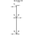
- FIG. 2 is a conceptual diagram illustrating a relationship between the centrifugal force of the movable scroll and the balance weight and the crankshaft deflection caused by the centrifugal force in the scroll compressor according to the first embodiment.
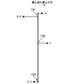
- FIG. 3 is a conceptual diagram illustrating the relationship between the centrifugal force of the movable scroll, the balance weight, and the deflection suppression weight and the crankshaft deflection caused by the centrifugal force in the scroll compressor according to the first embodiment.
- FIG. 4 is a longitudinal sectional view of the scroll compressor according to the second embodiment.
- FIG. 5 is a conceptual diagram showing the relationship between the movable scroll and the centrifugal force of each weight and the crankshaft deflection caused by the centrifugal force in the scroll compressor according to the second embodiment.
- FIG. 6 is a conceptual diagram showing the relationship between the centrifugal force of the movable scroll and each weight and the crankshaft deflection caused by the centrifugal force in the scroll compressor according to the modification of the second embodiment.
- Embodiment 1 of the Invention The scroll compressor (1) of the present embodiment is connected to a refrigerant circuit (not shown) that performs a refrigeration cycle, for example, and compresses the refrigerant.
- the scroll compressor (1) includes a casing (10), a compression mechanism (20), a housing (60), a drive motor (50), a lower bearing (70), and a crankshaft (40). I have.
- the casing (10) is a cylindrical sealed container having an axis in the vertical direction.
- a compression mechanism (20), a housing (60), a drive motor (50), and a lower bearing portion (70) are arranged in this order from top to bottom.
- the crankshaft (40) is arranged along the axis of the casing (10) inside the casing (10).
- the suction pipe (14) for guiding the refrigerant in the refrigerant circuit to the compression mechanism (20) is fixed through the upper portion of the casing (10).
- a discharge pipe (15) for discharging the refrigerant in the casing (10) to the refrigerant circuit is penetrated and fixed at the center of the casing (10).
- An oil reservoir (16) in which lubricating oil is stored is formed in the lower part of the casing (10).
- the crankshaft (40) includes a main shaft (41), an eccentric portion (42), and an oil suction portion (44).
- the main shaft (41) is disposed so as to extend in the vertical direction, and a protruding portion (43) whose side surface protrudes in the radial direction over the entire circumference is formed at the upper end thereof.
- the eccentric part (42) is formed eccentrically on the upper surface of the protruding part (43), that is, on the upper end of the main shaft (41).
- the eccentric portion (42) is formed in a cylindrical shape, protrudes upward from the upper surface of the protrusion (43), and its axis is eccentric with respect to the axis of the main shaft (41).
- the oil suction portion (44) is formed in a cylindrical shape, one end is fixed to the lower end of the main shaft (41), and the other end is immersed in the oil reservoir (16).
- An oil supply passage (45) is formed in the crankshaft (40) so as to penetrate from the oil suction portion (44) at the lower end to the eccentric portion (42) at the upper end.
- the compression mechanism (20) includes a fixed scroll (21) fixed to the upper surface of the housing (60) and a movable scroll (31) meshing with the fixed scroll (21).
- the fixed scroll (21) includes an end plate (22), a spiral (involute) wrap (23) formed on the front surface (the lower surface in FIG. 1) of the end plate (22), and the wrap (23) It has the outer peripheral wall part (24) which was located in the outer peripheral side and was formed continuously.
- the front end surface of the outer peripheral wall portion (24) is substantially flush with the front end surface of the wrap (23), and is fixed in contact with the upper surface of the housing (60).
- a suction port (25) is provided in the outer peripheral wall portion (24), and a suction pipe (14) is joined to the suction port (25) in an airtight manner.
- a discharge port (26) penetrating the end plate (22) in the thickness direction is provided at the center of the end plate (22) of the fixed scroll (21).
- the opening of the discharge port (26) on the back surface (upper surface in FIG. 1) side of the end plate (22) is closed by a lid member (27).
- the discharge port (26) communicates with the lower space (18) below the housing (60) through a passage (not shown) formed in the end plate (22) of the fixed scroll (21) and the housing (60). ing.
- the movable scroll (31) includes a mirror plate (32) and a spiral (involute) wrap (33) formed on the front surface (upper surface in FIG. 1) of the mirror plate (32).
- the wrap (33) of the movable scroll (31) meshes with the wrap (23) of the fixed scroll (21), and the end plate (22) of the fixed scroll (21) and the end plate (32) of the movable scroll (31)
- a compression chamber (30) composed of a space partitioned by both wraps (23, 33) is formed therebetween.
- a cylindrical boss (34) is integrally formed at the center of the movable scroll (31) on the back side of the end plate (32).
- a bearing (35) is press-fitted into the boss part (34), and an eccentric part (42) of the crankshaft (40) is rotatably supported by the bearing (35).
- the eccentric part (42) is connected with the back side of the movable scroll (31). Therefore, as shown in FIG. 2, when the crankshaft (40) rotates, the movable scroll (31) rotates eccentrically, and the centrifugal force A of the movable scroll (31) is eccentric with respect to the eccentric portion (42). Acts on direction.
- the housing (60) is formed in a dish shape as shown in FIG. 1, and has an annular outer peripheral portion and a central portion in which a concave recess (61) is formed on the upper surface.
- the housing (60) is press-fitted and fixed to the casing (10) at the outer peripheral portion and is in close contact with the casing (10). Therefore, the internal space of the casing (10) is partitioned by the housing (60) into an upper space (17) in which the compression mechanism (20) is accommodated and a lower space (18) in which the drive motor (50) is accommodated. .
- the housing (60) is formed with a through hole (62) penetrating from the bottom surface of the recess (61) to the lower end surface of the housing (60).
- An upper bearing (63) is press-fitted and fixed in the through hole (62), and the upper portion of the main shaft (41) is rotatably supported by the upper bearing (63).
- annular seal member (64) is provided on the outer peripheral edge of the recess (61) on the upper surface of the housing (60).
- the seal member (64) is held in contact with the back side of the end plate (32) of the movable scroll (31), and the space on the back side of the movable scroll (31) is disposed on the inner peripheral side of the seal member (64).
- a space on the outer peripheral side is formed by a recess (61) and an oil supply passage (45) communicating with the recess (61).
- a space on the outer peripheral side of the seal member (64) is formed by a gap between the outer peripheral portion of the housing (60) and the movable scroll (31).
- a key groove (not shown) formed on the back surface of the end plate (32) of the movable scroll (31) and an upper surface of the outer peripheral portion of the housing (60) are formed.
- An Oldham coupling (67) that is engaged with a keyway (not shown) and prevents the movable scroll (31) from rotating is provided.
- the drive motor (50) includes a stator (51) and a rotor (52).
- the stator (51) is fixed to the casing (10) by shrink fitting or the like.
- the rotor (52) is disposed coaxially with the stator (51) inside the stator (51), and is fixed to the main shaft (41) of the crankshaft (40) by shrink fitting or the like.
- the lower bearing part (70) includes a cylindrical bearing holding part (72), and a fixed part (73) fixed to the casing (10) and projecting outward on the outer peripheral surface of the bearing holding part (72). And have.
- a lower bearing (71) is press-fitted into the bearing holder (72), and the lower portion of the main shaft (41) is rotatably supported by the lower bearing (71).
- the main balance (41) of the crankshaft (40) is provided with a first balance weight (81) and a second balance weight (82). These two balance weights (81, 82) balance the centrifugal force A of the movable scroll (31) during rotation, and constitute a part of the weight (80) of the present invention.
- the first balance weight (81) and the second balance weight (82) are each formed in a C shape in plan view.
- the first balance weight (81) is located between the housing (60) and the rotor (52) (hereinafter referred to as the center portion) on the side opposite to the eccentric portion (42) with respect to the axis of the main shaft (41). It is attached to the side of the main shaft (41).
- the second balance weight (82) is a first balance weight (81) based on the axis of the main shaft (41) between the rotor (52) and the lower bearing portion (70) (hereinafter referred to as the lower portion). It is attached to the side surface of the main shaft (41) on the opposite side.
- the first balance weight (81) is provided so that the center of gravity is located on the opposite side of the eccentric portion (42) with respect to the axis of the main shaft (41), and the second balance weight (82) is The center of gravity is provided so as to be located on the same side as the eccentric portion (42) with respect to the axis of the main shaft (41).
- the first balance weight (42) is opposite to the eccentric direction of the eccentric portion (42). 81) is generated, and the centrifugal force C of the second balance weight (82) is generated in the same direction as the eccentric direction of the eccentric portion (42).
- the eccentric portion (42) has a direction opposite to the eccentric direction of the eccentric portion (42), that is, the centrifugal force A of the movable scroll (31).
- the force D in the opposite direction is generated, and the centrifugal force A of the movable scroll (31) is balanced.
- the upper deflection restraining weight (91), the central deflection restraining weight (92), and the lower deflection restraining weight (93) are provided on the main shaft (41) of the crankshaft (40). ) Is provided. These three deflection suppression weights (91, 92, 93) suppress the deflection of the crankshaft (40) caused by balancing with the centrifugal force A of the movable scroll (31). ).
- deflection suppression weights (91, 92, 93) are each formed in a C shape in plan view.
- the upper deflection restraining weight (91) is attached to the side surface of the protruding portion (43) (hereinafter referred to as the upper portion) opposite to the eccentric portion (42) with respect to the axis of the main shaft (41).
- the center part deflection suppression weight (92) is attached to the side surface of the center part of the main shaft (41) opposite to the upper deflection suppression weight (91) with respect to the axis of the main shaft (41).
- the lower deflection suppression weight (93) is attached to the side surface of the lower side of the main shaft (41) on the same side as the upper deflection suppression weight (91) with respect to the axis of the main shaft (41).
- the upper deflection suppression weight (91) is provided so that the center of gravity is located on the opposite side of the eccentric portion (42) with respect to the axis of the main shaft (41), and the central deflection suppression weight (92) Is provided so that the center of gravity is located on the same side as the eccentric part (42) with respect to the axis of the main shaft (41), and the lower deflection restraining weight (93) is centered on the axis of the main shaft (41) Are provided on the opposite side of the eccentric part (42).
- centrifugal force E and the centrifugal force A of the movable scroll (31), the centrifugal force F and the centrifugal force B of the first balance weight (81), and the centrifugal force G and the centrifugal force C of the second balance weight (82) are respectively The direction of action is the opposite. Therefore, the centrifugal forces E, F, G of the three deflection suppression weights (81, 82, 83) act to suppress the deflection of the crankshaft (40) caused by the centrifugal forces A, B, C.
- crankshaft (40) does not come into contact with each bearing (63, 71) and generates excessively large contact surface pressure, and wear of the bearing (63, 71) is suppressed.
- the weight (80) is provided on the main shaft (41) of the crankshaft (40) to balance the centrifugal force A of the movable scroll (31) during rotation, and the centrifugal force A of the movable scroll (31)
- the bending of the crankshaft (40) caused by balancing was suppressed.
- the rotation speed of a crankshaft (40) is high, it can suppress that bending of a crankshaft (40) becomes large.
- balance weights (81, 82) and three deflection suppression weights (91, 92, 93) are provided as the weight (80).
- the first balance weight (81) and the center part deflection suppression weight (92) are respectively attached to the center part of the main shaft (41) (between the housing (60) and the rotor (52)).
- the attachment position of the weight is not limited to this, and at least one of these two weights (81, 92) may be attached to the upper surface of the rotor (52).
- the second balance weight (82) and the lower deflection restraining weight (93) are respectively attached to the lower portion of the main shaft (41) (between the rotor (52) and the lower bearing portion (70)). ing.
- the attachment position of the weight is not limited to this, and at least one of these two weights (82, 93) may be attached to the lower surface of the rotor (52).
- the first balance weight (81) and the second balance weight (82) are each formed in a C shape in plan view and attached to the side surface of the main shaft (41).
- the first balance weight (81) has a center of gravity located on the opposite side of the eccentric portion (42) with respect to the axis of the main shaft (41)
- the second balance weight (82) has a center of gravity (41) As long as it is located on the same side as the eccentric part (42) with respect to the axis of
- the upper deflection restraining weight (91), the central deflection restraining weight (92), and the lower deflection restraining weight (93) are also formed in a C shape in plan view, and the side surface of the main shaft (41). It was made to attach to.
- the upper deflection restraining weight (91) has a center of gravity located on the opposite side of the eccentric portion (42) with respect to the axis of the main shaft (41).
- the shape and arrangement thereof are not limited to this.
- the first balance weight (81) is provided in the central portion of the main shaft (41).
- the present invention is not limited to this.
- the first balance weight (81) is provided on the upper portion of the main shaft (41).
- the centrifugal force B may be applied during rotation.
- the two balance weights (81, 82) and the three deflection suppression weights (91, 92, 93) are separately formed.
- the present invention is not limited to this.
- the first balance weight (81) and the central portion deflection suppression weight (92) may be integrally formed.
- the number of parts and the number of assembly steps can be reduced, and the scroll compressor (1) can be reduced. Cost can be reduced.
- Embodiment 2 a second embodiment of the present invention will be described in detail based on the drawings.
- the number of weights in the first embodiment is changed. That is, in the first embodiment, five weights (81, 82, 91 to 93) are provided on the main shaft (41). However, in the second embodiment, as shown in FIG. 4, three weights (101, 102, 103) are provided. It was made to provide.
- the main shaft (41) of the crankshaft (40) is provided with an upper weight (101), a central weight (102), and a lower weight (103). These three weights (101, 102, 103) are each formed in a C shape in plan view.
- the upper weight (101) is attached to the side surface of the upper portion of the main shaft (41) opposite to the eccentric portion (42) with respect to the axis of the main shaft (41). As shown in FIG. 5, the upper weight (101) is configured to generate a centrifugal force E having the same magnitude as the centrifugal force E of the upper deflection suppressing weight (91) of the first embodiment when rotating. Yes.
- the central weight (102) is attached to the side surface of the central portion of the main shaft (41) opposite to the upper weight (101) with respect to the axis of the main shaft (41).
- the central weight (102) has the same magnitude as the resultant force obtained by subtracting the centrifugal force B of the first balance weight (81) from the centrifugal force F of the central deflection suppressing weight (92) of the first embodiment during rotation.
- the centrifugal force FB is generated.
- the lower weight (103) is attached to the side surface of the lower side of the main shaft (41) on the same side as the upper weight (101) with respect to the axis of the main shaft (41).
- the lower weight (103) is a centrifugal force having the same magnitude as the resultant force obtained by subtracting the centrifugal force C of the second balance weight (82) from the centrifugal force G of the lower deflection restraining weight (93) of the first embodiment during rotation.
- GC is configured to occur.
- the centrifugal force B, the centrifugal force C, the centrifugal force E, the centrifugal force F, and the centrifugal force G constitute the first force, the second force, the third force, the fourth force, and the fifth force of the present invention, respectively. ing.
- the same state as in the first embodiment is formed. Specifically, two centrifugal forces B and C act to balance with the centrifugal force A of the movable scroll (31), and three centrifugal forces E and F to suppress the bending of the crankshaft (40). , G is formed. Therefore, also in the second embodiment, similarly to the first embodiment, it is possible to suppress the bearing wear at the time of high speed rotation and to suppress the decrease in bearing strength. In addition, since the total weight and the total volume of the weight can be reduced as compared with the first embodiment, the scroll compressor (1) can be reduced in weight, and the scroll compressor (1) can be reduced in size by reducing the installation space for the weight. Can be
- the central weight (102) is attached to the central portion (between the housing (60) and the rotor (52)) of the main shaft (41). It may be attached to the upper surface of 52).
- the lower weight (103) is attached to the lower part of the main shaft (41) (between the rotor (52) and the lower bearing part (70)).
- the lower weight (103) is attached to the lower surface of the rotor (52). You can attach it.
- the three weights (101, 102, 103) are each formed in a C shape in plan view, but the shape is not limited to this.
- the centrifugal force F is larger than the centrifugal force B and the centrifugal force G is larger than the centrifugal force C has been described.
- the centrifugal force F is smaller than the centrifugal force B and the centrifugal force G is smaller than the centrifugal force C
- a central weight (102) may be provided on the lower side
- a lower weight (103) may be provided on the opposite side of the upper weight (101).
- the upper weight (101) for generating the centrifugal force E and the central weight (102) for generating the resultant force FB of the centrifugal force F and the centrifugal force B are provided during rotation.
- the upper weight (101) and the central weight (102) are not limited to this, and as shown in FIG. 6, the upper weight (101) that generates the resultant force B + E of the centrifugal force B and the centrifugal force E during rotation, A central weight (102) for generating the centrifugal force F may be provided.
- the present invention is useful as a scroll compressor that is connected to a refrigerant circuit that performs a refrigeration cycle and compresses the refrigerant.
- Scroll compressor 20 Compression mechanism 21 Fixed scroll 31 Moveable scroll 40 crankshaft 41 spindle 42 Eccentric part 50 drive motor 52 Rotor 80 weights 81 1st balance weight 82 Second balance weight 91 Upper deflection restraining weight 92 Center part deflection suppression weight 93 Lower deflection suppression weight 101 Upper weight 102 Center weight 103 Lower weight
Landscapes
- Engineering & Computer Science (AREA)
- Mechanical Engineering (AREA)
- General Engineering & Computer Science (AREA)
- Rotary Pumps (AREA)
- Applications Or Details Of Rotary Compressors (AREA)
- Compressor (AREA)
Abstract
Description
本実施形態のスクロール圧縮機(1)は、例えば、冷凍サイクルを行う冷媒回路(図示省略)に接続され、冷媒を圧縮するためのものである。図1に示すように、スクロール圧縮機(1)は、ケーシング(10)、圧縮機構(20)、ハウジング(60)、駆動モータ(50)、下部軸受部(70)、クランク軸(40)を備えている。
本実施形態では、クランク軸(40)の主軸(41)にウェイト(80)を設けて、回転時に可動スクロール(31)の遠心力Aとバランスすると共に、可動スクロール(31)の遠心力Aとバランスすることで生じるクランク軸(40)の撓みを抑制するようにした。これにより、クランク軸(40)の回転数が高い場合に、クランク軸(40)の撓みが大きくなるのを抑制できる。その結果、従来に比べて、高速回転時における軸受の磨耗を抑制でき、磨耗による軸受耐力の低下を抑制できる。
上記実施形態1については、以下のような構成としてもよい。
次に、本発明の実施形態2を図面に基づいて詳細に説明する。実施形態2は、上記実施形態1のウェイトの数を変更したものである。つまり、上記実施形態1では、主軸(41)に5つのウエイト(81,82,91~93)が設けられていたが、実施形態2では、図4に示すように、3つのウェイト(101,102,103)を設けるようにした。
上記実施形態2については、以下のような構成としてもよい。
20 圧縮機構
21 固定スクロール
31 可動スクロール
40 クランク軸
41 主軸
42 偏心部
50 駆動モータ
52 ロータ
80 ウェイト
81 第1バランスウェイト
82 第2バランスウェイト
91 上部撓み抑制ウェイト
92 中央部撓み抑制ウェイト
93 下部撓み抑制ウェイト
101 上部ウェイト
102 中央部ウェイト
103 下部ウェイト
Claims (5)
- 固定スクロール(21)と可動スクロール(31)とを有する流体の圧縮機構(20)と、
主軸(41)と該主軸(41)の一端に偏心形成されて上記可動スクロール(31)の背面側に連結される偏心部(42)とを有するクランク軸(40)と、
ステータ(51)と上記クランク軸(40)の主軸(41)に連結されたロータ(52)とを有し、上記可動スクロール(31)を回転駆動させる駆動モータ(50)とを備えたスクロール圧縮機であって、
上記クランク軸(40)の主軸(41)及び上記駆動モータ(50)のロータ(52)の少なくとも一方には、回転時に上記可動スクロール(31)の遠心力とバランスすると共に、上記可動スクロール(31)の遠心力とバランスすることで生じる上記クランク軸(40)の撓みを抑制するウェイト(80)が設けられている
ことを特徴とするスクロール圧縮機。 - 請求項1において、
上記ウェイト(80)は、回転時に上記可動スクロール(31)の遠心力とバランスするバランスウェイト(81,82)と、上記可動スクロール(31)の遠心力と上記バランスウェイト(81,82)の遠心力とをバランスすることで生じる上記クランク軸(40)の撓みを抑制する撓み抑制ウェイト(91,92,93)とによって構成され、
上記バランスウェイト(81,82)は、重心が上記主軸(41)の軸心を基準に上記偏心部(42)とは反対側に位置する第1バランスウェイト(81)と、該第1バランスウェイト(81)よりも上記偏心部(42)から離れた位置に設けられ、重心が上記主軸(41)の軸心を基準に上記偏心部(42)と同じ側に位置する第2バランスウェイト(82)とからなり、
上記撓み抑制ウェイト(91,92,93)は、上記主軸(41)の上部に設けられ、重心が上記主軸(41)の軸心を基準に上記偏心部(42)とは反対側に位置する上部撓み抑制ウェイト(91)と、上記主軸(41)の中央部に設けられ、重心が上記主軸(41)の軸心を基準に上記偏心部(42)と同じ側に位置する中央部撓み抑制ウェイト(92)と、上記主軸(41)の下部に設けられ、重心が上記主軸(41)の軸心を基準に上記偏心部(42)とは反対側に位置する下部撓み抑制ウェイト(93)とからなり、上記上部撓み抑制ウェイト(91)、中央部撓み抑制ウェイト(92)及び下部撓み抑制ウェイト(93)は互いにバランスされている
ことを特徴とするスクロール圧縮機。 - 請求項2において、
上記第1バランスウェイト(81)及び第2バランスウェイト(82)の少なくとも1つは、上記上部撓み抑制ウェイト(91)、中央部撓み抑制ウェイト(92)及び下部撓み抑制ウェイト(93)の何れかと一体に形成されている
ことを特徴とするスクロール圧縮機。 - 請求項1において、
上記ウェイト(80)は、回転時に、上記可動スクロール(31)の遠心力とバランスする第1力及び第2力と、上記可動スクロール(31)の遠心力と上記第1力及び第2力とをバランスすることで生じる上記クランク軸(40)の撓みを抑制し、且つ互いにバランスのとれた第3力、第4力及び第5力とを発生させるものであり、上記主軸(41)の上部に設けられ上記第3力を遠心力として発生させる上部ウェイト(101)と、上記主軸(41)の中央部に設けられ上記第1力と上記第4力の合力を遠心力として発生させる中央部ウェイト(102)と、上記主軸(41)の下部に設けられ上記第2力と上記第5力の合力を遠心力として発生させる下部ウェイト(103)からなる
ことを特徴とするスクロール圧縮機。 - 請求項1において、
上記ウェイト(80)は、回転時に、上記可動スクロール(31)の遠心力とバランスする第1力及び第2力と、上記可動スクロール(31)の遠心力と上記第1力及び第2力とをバランスすることで生じる上記クランク軸(40)の撓みを抑制し、且つ互いにバランスのとれた第3力、第4力及び第5力とを発生させるものであり、上記主軸(41)の上部に設けられ上記第1力と上記第3力の合力を遠心力として発生させる上部ウェイト(101)と、上記主軸(41)の中央部に設けられ上記第4力を遠心力として発生させる中央部ウェイト(102)と、上記主軸(41)の下部に設けられ上記第2力と上記第5力の合力を遠心力として発生させる下部ウェイト(103)からなる
ことを特徴とするスクロール圧縮機。
Priority Applications (6)
| Application Number | Priority Date | Filing Date | Title |
|---|---|---|---|
| EP12834711.9A EP2762726B1 (en) | 2011-09-30 | 2012-09-27 | Scroll compressor |
| ES12834711.9T ES2670522T3 (es) | 2011-09-30 | 2012-09-27 | Compresor de espiral |
| CN201280045747.8A CN103827496B (zh) | 2011-09-30 | 2012-09-27 | 涡旋压缩机 |
| RU2014117848/06A RU2564473C1 (ru) | 2011-09-30 | 2012-09-27 | Спиральный компрессор |
| BR112014006979-4A BR112014006979B1 (pt) | 2011-09-30 | 2012-09-27 | compressor em espiral |
| US14/348,497 US9617997B2 (en) | 2011-09-30 | 2012-09-27 | Scroll compressor with balancing weights on the shaft |
Applications Claiming Priority (2)
| Application Number | Priority Date | Filing Date | Title |
|---|---|---|---|
| JP2011218356A JP5304867B2 (ja) | 2011-09-30 | 2011-09-30 | スクロール圧縮機 |
| JP2011-218356 | 2011-09-30 |
Publications (1)
| Publication Number | Publication Date |
|---|---|
| WO2013046692A1 true WO2013046692A1 (ja) | 2013-04-04 |
Family
ID=47994768
Family Applications (1)
| Application Number | Title | Priority Date | Filing Date |
|---|---|---|---|
| PCT/JP2012/006188 Ceased WO2013046692A1 (ja) | 2011-09-30 | 2012-09-27 | スクロール圧縮機 |
Country Status (8)
| Country | Link |
|---|---|
| US (1) | US9617997B2 (ja) |
| EP (1) | EP2762726B1 (ja) |
| JP (1) | JP5304867B2 (ja) |
| CN (1) | CN103827496B (ja) |
| BR (1) | BR112014006979B1 (ja) |
| ES (1) | ES2670522T3 (ja) |
| RU (1) | RU2564473C1 (ja) |
| WO (1) | WO2013046692A1 (ja) |
Cited By (3)
| Publication number | Priority date | Publication date | Assignee | Title |
|---|---|---|---|---|
| CN104863856A (zh) * | 2015-05-22 | 2015-08-26 | 合肥天鹅制冷科技有限公司 | 双涡盘的涡旋压缩机 |
| RU2629049C1 (ru) * | 2016-05-24 | 2017-08-24 | Леонид Михайлович Курин | Спиральный компрессор и способ его работы |
| WO2019027342A1 (ru) * | 2017-08-04 | 2019-02-07 | Леонид Михайлович КУРИН | Спиральный компрессор и способ его работы |
Families Citing this family (10)
| Publication number | Priority date | Publication date | Assignee | Title |
|---|---|---|---|---|
| CN104295498B (zh) * | 2013-06-27 | 2017-04-12 | 艾默生环境优化技术有限公司 | 压缩机 |
| JP6188828B2 (ja) * | 2014-01-20 | 2017-08-30 | 三菱電機株式会社 | スクロール圧縮機 |
| WO2015154036A1 (en) * | 2014-04-03 | 2015-10-08 | Trane International Inc. | Permanent magnet motor |
| KR101971819B1 (ko) | 2015-04-30 | 2019-04-23 | 에머슨 클라이미트 테크놀로지스 (쑤저우) 코., 엘티디. | 스크롤 압축기 |
| WO2017216876A1 (ja) * | 2016-06-14 | 2017-12-21 | 三菱電機株式会社 | スクロール圧縮機 |
| KR102554472B1 (ko) | 2018-05-17 | 2023-07-10 | 엘지전자 주식회사 | 삽입식 밸런스 웨이트 시스템 |
| CN110080978B (zh) * | 2019-04-24 | 2020-11-20 | 珠海格力节能环保制冷技术研究中心有限公司 | 曲轴变形平衡方法、装置,以及曲轴,涡旋压缩机 |
| CN114183347B (zh) * | 2021-12-17 | 2022-11-04 | 珠海格力电器股份有限公司 | 一种涡旋压缩机 |
| CN116066358A (zh) * | 2023-01-11 | 2023-05-05 | 浙江吉利控股集团有限公司 | 一种电动压缩机、汽车空调系统及汽车 |
| JP7620235B2 (ja) * | 2023-03-09 | 2025-01-23 | ダイキン工業株式会社 | 回転式圧縮機及び冷凍装置 |
Citations (6)
| Publication number | Priority date | Publication date | Assignee | Title |
|---|---|---|---|---|
| JPH0666268A (ja) * | 1992-08-20 | 1994-03-08 | Daikin Ind Ltd | スクロール流体機械 |
| JPH06317263A (ja) * | 1993-05-07 | 1994-11-15 | Mitsubishi Electric Corp | スクロール圧縮機 |
| JPH1061569A (ja) | 1996-08-19 | 1998-03-03 | Daikin Ind Ltd | スクロール圧縮機 |
| JPH1082379A (ja) * | 1996-09-06 | 1998-03-31 | Matsushita Electric Ind Co Ltd | スクロール圧縮機 |
| JP2004270654A (ja) * | 2003-03-12 | 2004-09-30 | Denso Corp | 回転型圧縮機 |
| JP2005188516A (ja) * | 2005-02-21 | 2005-07-14 | Sanyo Electric Co Ltd | スクロール圧縮機の製造方法 |
Family Cites Families (8)
| Publication number | Priority date | Publication date | Assignee | Title |
|---|---|---|---|---|
| JPH08312542A (ja) | 1995-05-17 | 1996-11-26 | Hitachi Ltd | スクロール圧縮機 |
| KR0162547B1 (ko) * | 1995-11-09 | 1999-01-15 | 김현진 | 스크롤 유체기계 |
| JP4625590B2 (ja) * | 2001-05-11 | 2011-02-02 | サンデン株式会社 | スクロール型流体機械 |
| JP2003021060A (ja) * | 2001-07-10 | 2003-01-24 | Toyota Industries Corp | 圧縮機、圧縮機のバランス取り方法及び治具 |
| RU2215190C1 (ru) * | 2002-03-05 | 2003-10-27 | Закрытое акционерное общество "Научно-исследовательский и конструкторский институт центробежных и роторных компрессоров им. В.Б. Шнеппа" | Горизонтальный спиральный компрессор |
| JP2006002823A (ja) | 2004-06-16 | 2006-01-05 | Mitsubishi Electric Corp | すべり軸受 |
| RU2343317C2 (ru) * | 2006-12-27 | 2009-01-10 | Закрытое акционерное общество "Научно-исследовательский и конструкторский институт центробежных и роторных компрессоров им. В.Б. Шнеппа" | Спиральная машина |
| KR100867623B1 (ko) * | 2007-03-21 | 2008-11-10 | 엘지전자 주식회사 | 압축기의 진동 저감장치 |
-
2011
- 2011-09-30 JP JP2011218356A patent/JP5304867B2/ja active Active
-
2012
- 2012-09-27 US US14/348,497 patent/US9617997B2/en active Active
- 2012-09-27 ES ES12834711.9T patent/ES2670522T3/es active Active
- 2012-09-27 EP EP12834711.9A patent/EP2762726B1/en active Active
- 2012-09-27 BR BR112014006979-4A patent/BR112014006979B1/pt active IP Right Grant
- 2012-09-27 WO PCT/JP2012/006188 patent/WO2013046692A1/ja not_active Ceased
- 2012-09-27 CN CN201280045747.8A patent/CN103827496B/zh active Active
- 2012-09-27 RU RU2014117848/06A patent/RU2564473C1/ru active
Patent Citations (6)
| Publication number | Priority date | Publication date | Assignee | Title |
|---|---|---|---|---|
| JPH0666268A (ja) * | 1992-08-20 | 1994-03-08 | Daikin Ind Ltd | スクロール流体機械 |
| JPH06317263A (ja) * | 1993-05-07 | 1994-11-15 | Mitsubishi Electric Corp | スクロール圧縮機 |
| JPH1061569A (ja) | 1996-08-19 | 1998-03-03 | Daikin Ind Ltd | スクロール圧縮機 |
| JPH1082379A (ja) * | 1996-09-06 | 1998-03-31 | Matsushita Electric Ind Co Ltd | スクロール圧縮機 |
| JP2004270654A (ja) * | 2003-03-12 | 2004-09-30 | Denso Corp | 回転型圧縮機 |
| JP2005188516A (ja) * | 2005-02-21 | 2005-07-14 | Sanyo Electric Co Ltd | スクロール圧縮機の製造方法 |
Cited By (3)
| Publication number | Priority date | Publication date | Assignee | Title |
|---|---|---|---|---|
| CN104863856A (zh) * | 2015-05-22 | 2015-08-26 | 合肥天鹅制冷科技有限公司 | 双涡盘的涡旋压缩机 |
| RU2629049C1 (ru) * | 2016-05-24 | 2017-08-24 | Леонид Михайлович Курин | Спиральный компрессор и способ его работы |
| WO2019027342A1 (ru) * | 2017-08-04 | 2019-02-07 | Леонид Михайлович КУРИН | Спиральный компрессор и способ его работы |
Also Published As
| Publication number | Publication date |
|---|---|
| JP5304867B2 (ja) | 2013-10-02 |
| JP2013076390A (ja) | 2013-04-25 |
| EP2762726A1 (en) | 2014-08-06 |
| BR112014006979A2 (pt) | 2017-04-04 |
| BR112014006979B1 (pt) | 2021-05-25 |
| CN103827496A (zh) | 2014-05-28 |
| CN103827496B (zh) | 2016-03-02 |
| US9617997B2 (en) | 2017-04-11 |
| EP2762726A4 (en) | 2015-04-15 |
| EP2762726B1 (en) | 2018-02-21 |
| RU2564473C1 (ru) | 2015-10-10 |
| US20140248169A1 (en) | 2014-09-04 |
| ES2670522T3 (es) | 2018-05-30 |
Similar Documents
| Publication | Publication Date | Title |
|---|---|---|
| JP5304867B2 (ja) | スクロール圧縮機 | |
| JP5304868B2 (ja) | スクロール圧縮機 | |
| JP5879532B2 (ja) | スクロール型圧縮機 | |
| WO2017199435A1 (ja) | スクロール圧縮機 | |
| JP5494465B2 (ja) | スクロール圧縮機 | |
| WO2017158665A1 (ja) | スクロール圧縮機 | |
| JP2014129755A (ja) | ロータリ式圧縮機 | |
| JP7795695B2 (ja) | スクロール型圧縮機 | |
| JP6340964B2 (ja) | 回転式圧縮機 | |
| WO2014108973A1 (ja) | スクロール圧縮機 | |
| JP6273729B2 (ja) | 回転式圧縮機 | |
| JP2015021471A (ja) | 圧縮機 | |
| WO2017115559A1 (ja) | スクロール圧縮機 | |
| JP2016017474A (ja) | 回転式圧縮機 | |
| JP6464583B2 (ja) | 回転式圧縮機 | |
| JP2016217233A (ja) | スクロール圧縮機 | |
| JP6029517B2 (ja) | スクロール圧縮機 | |
| JP2012036841A (ja) | 圧縮機 | |
| JP2019148188A (ja) | 圧縮機 | |
| JP2015038328A (ja) | 圧縮機 | |
| JP6131795B2 (ja) | 回転式圧縮機 | |
| JP2017002814A (ja) | ロータリ型圧縮機 | |
| JP2015038332A (ja) | スクロール圧縮機 | |
| JP2017101634A (ja) | スクロール圧縮機 | |
| WO2018021058A1 (ja) | スクロール圧縮機 |
Legal Events
| Date | Code | Title | Description |
|---|---|---|---|
| 121 | Ep: the epo has been informed by wipo that ep was designated in this application |
Ref document number: 12834711 Country of ref document: EP Kind code of ref document: A1 |
|
| WWE | Wipo information: entry into national phase |
Ref document number: 2012834711 Country of ref document: EP |
|
| WWE | Wipo information: entry into national phase |
Ref document number: 14348497 Country of ref document: US |
|
| NENP | Non-entry into the national phase |
Ref country code: DE |
|
| ENP | Entry into the national phase |
Ref document number: 2014117848 Country of ref document: RU Kind code of ref document: A |
|
| REG | Reference to national code |
Ref country code: BR Ref legal event code: B01A Ref document number: 112014006979 Country of ref document: BR |
|
| ENP | Entry into the national phase |
Ref document number: 112014006979 Country of ref document: BR Kind code of ref document: A2 Effective date: 20140324 |