WO2013046828A1 - 画像処理装置、方法、プログラムおよび記録媒体並びに撮像装置 - Google Patents
画像処理装置、方法、プログラムおよび記録媒体並びに撮像装置 Download PDFInfo
- Publication number
- WO2013046828A1 WO2013046828A1 PCT/JP2012/065837 JP2012065837W WO2013046828A1 WO 2013046828 A1 WO2013046828 A1 WO 2013046828A1 JP 2012065837 W JP2012065837 W JP 2012065837W WO 2013046828 A1 WO2013046828 A1 WO 2013046828A1
- Authority
- WO
- WIPO (PCT)
- Prior art keywords
- filter
- pixel
- pixels
- size
- image
- Prior art date
- Legal status (The legal status is an assumption and is not a legal conclusion. Google has not performed a legal analysis and makes no representation as to the accuracy of the status listed.)
- Ceased
Links
Images


Classifications
-
- G—PHYSICS
- G06—COMPUTING OR CALCULATING; COUNTING
- G06T—IMAGE DATA PROCESSING OR GENERATION, IN GENERAL
- G06T3/00—Geometric image transformations in the plane of the image
- G06T3/40—Scaling of whole images or parts thereof, e.g. expanding or contracting
- G06T3/4015—Image demosaicing, e.g. colour filter arrays [CFA] or Bayer patterns
-
- H—ELECTRICITY
- H04—ELECTRIC COMMUNICATION TECHNIQUE
- H04N—PICTORIAL COMMUNICATION, e.g. TELEVISION
- H04N25/00—Circuitry of solid-state image sensors [SSIS]; Control thereof
- H04N25/60—Noise processing, e.g. detecting, correcting, reducing or removing noise
- H04N25/68—Noise processing, e.g. detecting, correcting, reducing or removing noise applied to defects
-
- H—ELECTRICITY
- H04—ELECTRIC COMMUNICATION TECHNIQUE
- H04N—PICTORIAL COMMUNICATION, e.g. TELEVISION
- H04N25/00—Circuitry of solid-state image sensors [SSIS]; Control thereof
- H04N25/70—SSIS architectures; Circuits associated therewith
- H04N25/76—Addressed sensors, e.g. MOS or CMOS sensors
- H04N25/77—Pixel circuitry, e.g. memories, A/D converters, pixel amplifiers, shared circuits or shared components
- H04N25/778—Pixel circuitry, e.g. memories, A/D converters, pixel amplifiers, shared circuits or shared components comprising amplifiers shared between a plurality of pixels, i.e. at least one part of the amplifier must be on the sensor array itself
Definitions
- the present invention relates to an image processing apparatus, a method, a program, a recording medium, and an imaging apparatus, and more particularly, to a technique for reducing a fixed pattern generated due to a repetition period for each predetermined pixel group of an imaging element.
- FIG. 20 is a diagram illustrating an example of a color filter array provided in the image sensor.
- the color filter array shown in FIG. 20 is a primary color Bayer array.
- the Bayer array includes a basic array pattern of 2 ⁇ 2 pixels, and this basic array pattern is repeatedly arranged in the horizontal direction and the vertical direction.
- the basic array pattern includes three primary colors of red (R), blue (B), and green (G) pixels.
- G pixel there are a G r pixels adjacent R pixels in the horizontal direction, and G b pixels adjacent the B pixels in the horizontal direction.
- the G r pixels and G b pixel different colors of pixels adjacent in the horizontal direction.
- the pixel value of G r pixels by leakage of light from the adjacent R pixel (color mixing) becomes larger than the pixel value of G b pixels in the neighborhood, and the pixel value of the pixel values and G b pixel of G r pixels
- a fixed pattern appears when this step is periodically repeated according to the basic array pattern.
- FIG. 21 shows a new mosaic color filter array proposed by the present applicant (Japanese Patent Application No. 2011-34627).
- the basic array pattern of this color filter array is 6 ⁇ 6 pixels, and the basic array pattern includes 20 G pixels and 8 R and B pixels, respectively.
- this basic array pattern there are many pixels having the same color but different colors of adjacent pixels (eight pixels) depending on the position in the basic array pattern. For this reason, a fixed pattern due to color mixing is likely to occur.
- the color filter array shown in FIG. 21 since the basic array pattern size is larger than the Bayer array, the fixed pattern is easily noticeable.
- CMOS Complementary Metal-Oxide Semiconductor
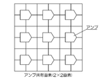
- a pixel sharing amplifier is embedded in a CMOS base.
- 2 ⁇ 2 4 pixels share one amplifier A. Due to the underlying structure of the image sensor, the output level varies depending on the pixel position relative to the shared amplifier (upper left, upper right, lower left, and lower right positions with respect to the amplifier A). A corresponding fixed pattern is generated.
- the filter process is performed using a filter having a uniform filter coefficient as shown in FIG. 24, the fixed pattern can be reduced.
- the image is blurred and the details are lost, and the image quality is deteriorated.
- Patent Document 1 discloses an image signal that can effectively remove noise of a solid-state image sensor without losing necessary components in the image signal by performing noise reduction according to the output signal level of the solid-state image sensor.
- a processing device has been proposed. This image signal processing apparatus determines the magnitude of the image signal level generated by the solid-state imaging device, and changes the degree of low-pass filtering according to the magnitude.
- Patent Document 2 discloses a method of descreening a halftone area in an image, and a low-pass filter is modified and applied when descreening a halftone area.
- Patent Document 3 the filter size is changed so that the filter size of the low-pass filter monotonously increases with respect to the increase of the relative distance based on the relative distance from the in-focus position, and the strength of noise reduction processing for the video signal is disclosed.
- An imaging device is described in which the change is made.
- Patent Document 1 reduces optical shot noise that depends on the output signal level of a solid-state imaging device. For this reason, the invention described in Patent Document 1 is not effective in reducing the fixed pattern, and a strong fixed pattern remains.
- Patent Documents 2 and 3 do not reduce the fixed pattern.
- the filter correction method described in Patent Document 2 and the filter size changing method described in Patent Document 3 do not reduce the fixed pattern.
- the present invention has been made in view of such circumstances, and an image processing apparatus, method, program, and program capable of reducing a fixed pattern generated due to a repetition period of a pixel structure of an image sensor and leaving details.
- An object is to provide a recording medium and an imaging apparatus.
- an invention according to an aspect of the present invention is photographed by an imaging unit including an imaging device having a pixel structure with a repetition period of M ⁇ N (M, N: integer of 2 or more) pixels.
- Image acquisition means for acquiring the obtained image, and a filter with a filter size of K ⁇ L (K, L: M ⁇ K, N ⁇ L), the filter coefficient set in the filter, and the image acquisition Filter processing means for calculating a pixel value of the target pixel by performing a convolution operation with a pixel value of the K ⁇ L pixel extracted on the basis of the target pixel in the image acquired by the means, and set in the filter Filter coefficients weighted near the center of the filter and corresponding to pixels having the same positional relationship on the pixel structure of the M ⁇ N pixels, the total of the filter coefficients within the filter size are all the same. In It is set to so that.
- the filter coefficient of the filter has a weighted filter coefficient in the vicinity of the center, the detail of the image after the filter processing by the filter processing means can be prevented from being lost.
- a filter with a filter size of K ⁇ L that is slightly larger than the pixel structure of the M ⁇ N pixel repetition period of the image sensor is used.
- the filter coefficients are set so that the sum of the filter coefficients in the filter size corresponding to the pixels having the same positional relationship on the M ⁇ N pixel structure is all the same. For this reason, a substantial smoothing process is performed on the pixel value of the M ⁇ N pixels. Therefore, it is possible to reduce the fixed pattern generated due to the pixel structure having the repetition period of the M ⁇ N pixels.
- the image sensor has a predetermined basic array pattern including three color filters on a plurality of pixels arrayed in the horizontal direction and the vertical direction. It is a color image sensor repeatedly arranged in the direction, and the pixel structure of the M ⁇ N pixel repetition period corresponds to the predetermined basic array pattern. That is, in the image output from the image sensor, a fixed pattern is generated due to the period of the pixel structure (repetition of a predetermined pixel group) of the image sensor, and the pixel structure has three color filters. It corresponds to a predetermined basic arrangement pattern.
- the image sensor is an image sensor having an element structure that shares an amplifier for each predetermined pixel group, and the pixel structure of the M ⁇ N pixel repetition period is , Corresponding to the predetermined pixel group. That is, in the image output from the image sensor, a fixed pattern is generated due to the period of the pixel structure of the image sensor, and the pixel structure corresponds to the base structure including the shared amplifier of the image sensor. It is.
- the imaging element has a predetermined basic arrangement pattern including three color filters on a plurality of pixels arranged in the horizontal direction and the vertical direction, in the horizontal direction and A color imaging device having an element structure that is repeatedly arranged in the vertical direction and shares an amplifier for each predetermined pixel group, and the pixel structure having a repetition period of M ⁇ N pixels includes the predetermined basic array pattern and the The period is the least common multiple with a predetermined pixel group.
- the basic array pattern includes color filters of three primary colors of red (R), green (G), and blue (B), and the basic array pattern includes N
- This basic array pattern includes at least nine pixels, and there are a plurality of pixels of the same color, and a fixed pattern is likely to occur.
- the present invention is more effective for an image obtained from an image sensor having such a basic arrangement pattern.
- the filter processing means is a pixel of interest in K ⁇ L pixels of a region to be processed by the filter, and a color filter of the same color as the color filter of the pixel of interest.
- the pixel value of the pixel of interest is calculated by a convolution operation of the pixel values of the corresponding pixels and the filter coefficients of the filter corresponding to these pixels.
- a fixed pattern size acquisition unit that acquires a fixed pattern size corresponding to an M ⁇ N pixel that is a repetition period of the pixel structure of the image sensor, and the acquired fixed pattern
- the sum of filter coefficients within the filter size having filter coefficients weighted near the center of the filter size based on size and corresponding to pixels in the same positional relationship on the element structure of the M ⁇ N pixels are further provided with filter coefficient calculation means for calculating the filter coefficients so that they are all the same, and the filter processing means acquires the filter coefficients calculated by the filter coefficient calculation means. According to this, if a fixed pattern size can be acquired, a filter coefficient that can reduce the fixed pattern can be calculated.
- the imaging element has a predetermined basic arrangement pattern including three color filters on a plurality of pixels arranged in the horizontal direction and the vertical direction, in the horizontal direction and It is a color image sensor repeatedly arranged in the vertical direction, and the fixed pattern size acquisition means acquires the size of the predetermined basic array pattern as the fixed pattern size.
- the image sensor is an image sensor having an element structure that shares an amplifier for each predetermined pixel group, and the fixed pattern size acquisition unit shares the amplifier.
- the image size of a predetermined pixel group is acquired as the fixed pattern size.
- the imaging element has a predetermined basic arrangement pattern including three color filters on a plurality of pixels arranged in the horizontal direction and the vertical direction, in the horizontal direction and A color imaging device that is repeatedly arranged in the vertical direction and has an element structure that shares an amplifier for each predetermined pixel group, and the fixed pattern size acquisition unit shares the amplifier with the size of the predetermined basic array pattern A size that is the least common multiple of the image size of the predetermined pixel group is acquired as the fixed pattern size.
- the size of the basic array pattern of the three color filters of the image sensor, the image size of the pixel group using one shared amplifier on the base of the image sensor, or the least common multiple of these sizes can be obtained as a size.
- the image processing apparatus further includes a filter size calculation unit that calculates the K ⁇ L filter size based on the M ⁇ N fixed pattern size, and the filter coefficient calculation unit includes: A filter coefficient corresponding to the filter size calculated by the filter size calculating means is calculated.
- An image processing method acquires an image photographed by an imaging unit including an imaging element having a pixel structure with a repetition period of M ⁇ N (M, N: integer of 2 or more) pixels. And (a) setting a target pixel in the acquired image and extracting a K ⁇ L (K, L: integer of M ⁇ K, N ⁇ L) pixel based on the target pixel; (B) A filter having a filter size of K ⁇ L is calculated, and the pixel value of the target pixel is calculated by performing a convolution operation on the filter coefficient set in the filter and the pixel value of the extracted K ⁇ L pixel.
- a filter coefficient set for the filter including a step, and (c) repeatedly executing the step (a) and the step (b) while moving the pixel of interest one pixel at a time with respect to the acquired image Is weighted near the center of the filter Is and and corresponds to a pixel in the same positional relationship on the element structure of the M ⁇ N pixels, the sum of the filter coefficients in said filter size is set so that all the same.
- An image processing program acquires an image photographed by an imaging unit including an imaging element having a pixel structure with a repetition period of M ⁇ N (M, N: integer greater than or equal to 2) pixels. And (a) a function of setting a target pixel in the acquired image and extracting a K ⁇ L (K, L: integer of M ⁇ K, N ⁇ L) pixel based on the target pixel; (B) A filter having a filter size of K ⁇ L is calculated, and the pixel value of the target pixel is calculated by performing a convolution operation on the filter coefficient set in the filter and the pixel value of the extracted K ⁇ L pixel.
- a function, and (c) a function of repeatedly executing the function (a) and the function (b) while moving the target pixel one pixel at a time with respect to the acquired image, and is set in the filter.
- the filter coefficient The sum of the filter coefficients in the filter size corresponding to the pixels having the same positional relationship on the element structure of the M ⁇ N pixels is set to be the same. ing.
- An imaging apparatus acquires an imaging unit including an imaging optical system and an imaging element on which a subject image is formed via the imaging optical system, and an image output from the imaging unit.
- the image image obtaining means for performing the image processing and any one of the image processing apparatuses described above.
- a filter having a filter size of K ⁇ L (K, L: integer of M ⁇ K, N ⁇ L) that is slightly larger than that of an image sensor having a pixel structure with a repetition period of M ⁇ N pixels.
- the filter coefficients of the filter are weighted near the center, and the sum of the filter coefficients within the filter size corresponding to the pixels in the same positional relationship on the element structure of the M ⁇ N pixels is The filter coefficients are set so that they are all the same. For this reason, it is possible to prevent loss of image details after filtering by the filter. Furthermore, it is possible to reduce a fixed pattern generated due to the pixel structure having the repetition period of the M ⁇ N pixels.
- positioned at an image pick-up element The figure which shows an example of the filter coefficient of the filter for fixed pattern reduction corresponding to the color filter arrangement
- FIG. 1 is a block diagram showing a first embodiment of an imaging apparatus according to the present invention.
- the flowchart which shows 1st Embodiment of the image processing method in the imaging device shown in FIG.
- the block diagram which shows 2nd Embodiment of the imaging device which concerns on this invention.
- FIG. 7 is a flowchart showing a second embodiment of the image processing method in the imaging apparatus shown in FIG.
- the block diagram which shows 3rd Embodiment of the imaging device which concerns on this invention.
- FIG. 11B The figure which shows the example of the amplifier shared pixel size of an image sensor
- FIG. 14B 14 is a flowchart illustrating a fourth embodiment of an image processing method in the imaging apparatus illustrated in FIG.
- the block diagram which shows 5th Embodiment of the imaging device which concerns on this invention.
- the figure which shows the further another example of the mosaic-shaped color filter arrangement
- FIG. 17 is a flowchart showing the fifth embodiment of the image processing method in the imaging apparatus shown in FIG.
- sequence provided in the image pick-up element The figure which shows the novel mosaic color filter arrangement
- the figure which shows the example of application of the filter which has the filter coefficient of the center weight The figure which shows the example of application of the filter which has the filter coefficient of the center weight Diagram showing a filter with uniform filter coefficients
- FIG. 1A shows an example of a mosaic color filter array arranged on each photoelectric conversion element of an image pickup element in which photoelectric conversion elements are two-dimensionally arranged.
- the color filter array shown in FIG. 1A includes a basic array pattern (pattern indicated by a thick frame) including a square array pattern corresponding to 6 ⁇ 6 pixels.
- This basic array pattern is repeatedly arranged in the horizontal direction and the vertical direction. That is, in this color filter array, R, G, B color filters (R filter, G filter, B filter) have a periodicity corresponding to the basic array pattern (6 ⁇ 6 pixels) in the horizontal and vertical directions. Has been placed.
- the basic array pattern shown in FIG. 1A can be regarded as an array in which a 3 ⁇ 3 pixel a array and a 3 ⁇ 3 pixel b array are alternately arranged in the horizontal and vertical directions.
- G filters which are luminance system pixels, are arranged at the four corners and the center, and are arranged on both diagonal lines.
- the R filter is arranged in the horizontal direction and the B filter is arranged in the vertical direction with the central G filter interposed therebetween.
- the B filter is arranged in the horizontal direction and the R filter is arranged in the vertical direction with the central G filter interposed therebetween. That is, in the a array and the b array, the positional relationship between the R filter and the B filter is reversed, but the other arrangements are the same.
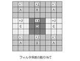
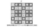
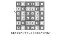
- FIG. 1B shows filter coefficients of a filter for reducing the fixed pattern.
- the filter shown in FIG. 1B has a 9 ⁇ 9 filter size larger than the size of the basic array pattern (fixed pattern).
- the filter coefficients of each area are assigned as follows: the filter coefficient of the center area is 4, the filter coefficients of the upper, lower, left and right areas are 2, 4 corner areas
- the filter coefficient of is 1. That is, the filter coefficient is weighted near the center of the filter (the pixel is closer to the center of the filter, and the filter coefficient is set to be larger).
- each area is A, B, C, D, each area A to D and 9 ⁇ 9
- FIG. 2B The relationship with each area obtained by dividing the filter into nine parts is as shown in FIG. 2B.
- the basic arrangement pattern area D corresponds to the central area of the nine divided areas of the filter
- the upper and lower areas of the central area correspond to the basic arrangement pattern area B.
- the left and right areas in the center correspond to the area C of the basic array pattern.
- the four corner areas correspond to the area A of the basic array pattern.
- the numbers of areas A, B, C, and D on the filter are 4: 2: 2: 1, respectively.
- the filter coefficients in the 9 ⁇ 9 filter are weighted near the center, so that the details of the filtered image can be prevented from being lost.
- FIG. 3 is a diagram illustrating another example of the mosaic color filter array arranged in the image sensor and an example of filter coefficients of the corresponding fixed pattern reduction filter.
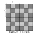
- the color filter array shown in FIG. 3 includes a basic array pattern composed of square array patterns corresponding to 3 ⁇ 3 pixels, and this basic array pattern is repeatedly arranged in the horizontal direction and the vertical direction. Note that the basic array pattern shown in FIG. 3 corresponds to the a array of 3 ⁇ 3 pixels shown in FIG. 1A.
- the filter for reducing the fixed pattern has a filter size of 5 ⁇ 5.
- This filter has a filter coefficient weighted near the center, and has a filter coefficient within a 5 ⁇ 5 filter size corresponding to pixels having the same positional relationship on the basic arrangement pattern of 3 ⁇ 3 pixels. The total is set to be the same.
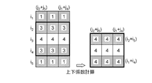
- FIG. 4A shows the filter coefficients of the 5 ⁇ 5 filter.
- the set of column j 1 and column j 4 and the set of column j 2 and column j 5 on this filter have the same positional relationship on the basic array pattern.
- filter coefficients assigned to these columns are added, filter coefficients such as column (j 1 + j 4 ) and column (j 2 + j 5 ) shown on the right side of FIG. 4B are obtained.
- the set of row i 1 and row i 4 and the set of row i 2 and row i 5 on this filter have the same positional relationship on the basic array pattern.
- the filter coefficients assigned to these rows are added, the rows (i 1 + i 4 ) and the row (i 2 + i 5 ) shown on the right side in FIG. 4C are obtained. Filter coefficients can be obtained.
- the filter coefficients corresponding to each position on the basic array pattern obtained by adding the 5 ⁇ 5 filter coefficients according to the above procedure as described above are all 4.
- the filter rows are i m , i (m ⁇ 1) ,..., I 1 , i 0 (one or more rows located in the center of the filter and matching the filter coefficient array), i ⁇ 1.
- the columns are j n , j (n ⁇ 1) ,..., J 1 , j 0 (located in the center of the filter, and the array of filter coefficients is Match one or more columns), j ⁇ 1 ,..., J ⁇ (n ⁇ 1) , j ⁇ n .
- the filter coefficients of columns having a predetermined positional relationship with respect to the middle column j 0 are added, and (j n + j ⁇ 1 ), (j (n ⁇ 1) + j ⁇ 2 ),. 1 + j ⁇ n ). Thereafter, the filter coefficients of the rows having a predetermined positional relationship across the central row i 0 are added, and (i m + i ⁇ 1 ), (i (m ⁇ 1) + i ⁇ 2 ),..., (I 1 + i -M ).
- the filter coefficient values (m + (number of rows of i 0 )) ⁇ (n + (number of columns of j 0 )) obtained by the above addition are all equal.
- m and n are odd numbers, they are obtained by adding (j (n + 1) / 2 + j (n + 1) / 2 ) and (i (m + 1) / 2 + i (m + 1) / 2 ).
- the value of the filter coefficient is also equal to the filter coefficient.
- FIG. 5 is a block diagram showing a first embodiment of the imaging apparatus according to the present invention.
- the imaging device 10-1 shown in FIG. 5 records the captured image on a recording medium 12 such as a memory card.
- the overall operation of the imaging apparatus 10-1 is centrally controlled by a central processing unit (CPU, Central Processing Unit) 14.
- CPU Central Processing Unit
- the CPU 14 controls each unit of the imaging device 10-1 based on input signals from operation units such as a shutter button and a power button (not shown).
- the CPU 14 performs, for example, lens drive control, shooting operation control, image processing control, image data recording / reproduction control, liquid crystal monitor display control, and the like in accordance with an input signal from the operation unit.
- the subject light that has passed through the photographing lens 16 is imaged on the light receiving surface of the image sensor 18.
- the subject image formed on the image sensor 18 is converted into a signal charge corresponding to the amount of incident light by the photoelectric conversion element.
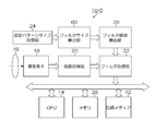
- the image acquisition unit 20 sequentially reads out the signal charge accumulated in each photoelectric conversion element of the image sensor 18 from the image sensor 18 as a voltage signal (image signal) and outputs the voltage signal to the filter processing unit 22.
- the image signal output from the image acquisition unit 20 to the filter processing unit 22 is an R, G, B signal (digital signal) indicating an R, G, B mosaic image corresponding to the color filter array of the image sensor 18.
- the image sensor 18 is not limited to a CCD (Charge Coupled Device) image sensor, but may be another type of image sensor such as a CMOS (Complementary Metal-Oxide Semiconductor) image sensor.
- CCD Charge Coupled Device
- CMOS Complementary Metal-Oxide Semiconductor
- the filter processing unit 22 is given a filter coefficient of K ⁇ L filter size from the filter coefficient calculation unit 26.
- the filter processing unit 22 convolves the pixel value of K ⁇ L pixels extracted based on the target pixel to be filtered in the image acquired from the image acquisition unit 20 with the filter coefficient of the filter size of K ⁇ L. Calculation is performed to calculate the pixel value of the target pixel.
- the fixed pattern size acquisition unit 24 acquires a fixed pattern size corresponding to the repetition period of the pixel structure of the image sensor 18 and outputs size information indicating the fixed pattern size to the filter coefficient calculation unit 26.
- size information indicating the fixed pattern size information set in advance according to the type of the image sensor 18 is input. For example, in the case of an image sensor having a color filter array including the basic array pattern shown in FIG. 1B, a fixed pattern size of 6 ⁇ 6 is input. In the case of an image sensor having a color filter array including the 3 ⁇ 3 basic array pattern shown in FIG. 3, a fixed pattern size of 3 ⁇ 3 is input.
- the filter coefficient calculation unit 26 calculates a filter coefficient having a filter size larger than the fixed pattern size based on the size information indicating the fixed pattern size input from the fixed pattern size acquisition unit 24.
- the filter coefficient calculation unit 26 is an integer of K ⁇ L (K, L: M ⁇ K, N ⁇ L). The filter coefficient corresponding to the filter size is calculated.
- the filter count calculation unit 26 has a filter coefficient weighted near the center, and corresponds to pixels in the same positional relationship on the fixed pattern. The filter coefficients are calculated so that the total of the filter coefficients becomes the same.
- the mosaic image data (RAW data) for one screen on which the fixed pattern has been reduced by the filter processing unit 22 is temporarily input to a memory (SDRAM; Synchronous Dynamic Random Access Memory) 28 and temporarily stored.
- SDRAM Synchronous Dynamic Random Access Memory
- the image data temporarily stored in the memory 28 is appropriately read out by a digital signal processing unit (not shown).
- white balance correction, gamma correction, and synchronization processing all RGB color information for each pixel from the RGB mosaic image associated with the color filter array of the single-plate color image sensor 18
- Processing for calculating (converting into simultaneous equations) also referred to as demosaic processing
- YC processing for generating luminance signal Y and color difference signals Cr and Cb, contour correction, color correction, and the like are performed.
- the image data is subjected to compression processing conforming to the JPEG (Joint Photographic Experts Group) standard and recorded on the recording medium 12.
- JPEG Joint Photographic Experts Group
- the image data is output and displayed on a liquid crystal monitor (not shown).
- FIG. 6 is a flowchart showing a first embodiment of an image processing method in the imaging apparatus 10-1.
- the image acquisition unit 20 acquires a mosaic image corresponding to the color filter array in the image sensor 18 via the shooting lens 16 and the image sensor 18 (step S10). ).
- the fixed pattern size acquisition unit 24 acquires a fixed pattern size (M ⁇ N) (M, N: an integer equal to or greater than 2) corresponding to the repetition period of the pixel structure of the image sensor 18 (step S12). Size information indicating the pattern size (M ⁇ N) is output to the filter coefficient calculation unit 26. Based on the size information of the fixed pattern size (M ⁇ N) input from the fixed pattern size acquisition unit 24, the filter coefficient calculation unit 26 has a filter size (K ⁇ L) (K, L: A filter coefficient of M ⁇ K, N ⁇ L) is calculated (step S14). It is preferable that the filter coefficient is calculated and stored in advance and the stored filter coefficient is used.
- the filter size (K ⁇ L) is set to an appropriate size larger than the fixed pattern size (M ⁇ N).
- the filter size is too large, the blur of the image after the filter processing becomes large. Therefore, it is preferable to define an upper limit for the filter size (K ⁇ L) with respect to the fixed pattern size (M ⁇ N) as shown in the following equations (1) and (2).
- the filter processing unit 22 performs a filter process based on the mosaic image acquired in step S10 and the filter coefficient calculated in step S14 (step S16).
- a target pixel (x, y) is set in the acquired image, and K ⁇ L pixels are extracted with reference to the target pixel (x, y). Then, the pixel value of the pixel of interest (x, y) is calculated by a convolution operation (product-sum operation) between the extracted K ⁇ L pixels and a filter coefficient having a filter size of K ⁇ L.
- the G pixel of the K ⁇ L pixel mosaic pixel and the filter coefficient corresponding to the position of the G pixel are used. Perform a convolution operation.
- the target pixel is an R pixel or a B pixel
- a convolution operation is performed using a pixel of the same color and a filter coefficient corresponding to the position of the pixel.
- the pixel value after the filter processing is calculated.
- the position of the pixel of interest (x, y) is moved pixel by pixel within the range of 1 ⁇ x ⁇ W and 1 ⁇ y ⁇ H.
- the above filtering process is repeated. Thereby, the filtering process is performed on all the pixels of the mosaic image.
- the mosaic image that has been subjected to the filter processing for reducing the fixed pattern as described above is then subjected to digital signal processing such as normal white balance correction, gamma correction, synchronization processing, and YC processing (step S18).
- digital signal processing such as normal white balance correction, gamma correction, synchronization processing, and YC processing (step S18).
- the YC-processed luminance signal Y and color difference signal are compressed and then recorded on the recording medium 12 (step S20).
- FIG. 7 is a block diagram showing a second embodiment of the imaging apparatus according to the present invention.
- symbol is attached
- the imaging apparatus 10-2 according to the second embodiment illustrated in FIG. 7 uses a basic array pattern size acquisition unit 30 and a filter coefficient calculation instead of the fixed pattern size acquisition unit 24 and the filter coefficient calculation unit 26 according to the first embodiment. It is different in that the portion 32 is provided.
- the basic array pattern size acquisition unit 30 acquires the size of the basic array pattern (basic array pattern size) of the RGB filter of the mosaic color filter array provided in the image sensor 18.
- the basic array pattern indicated by the thick inner frame which is the minimum repeating pattern in the horizontal and vertical directions of the RGB filter, is 6 ⁇ 6 pixels. Therefore, the basic array pattern size of the color filter array shown in FIG. 8 is 6 ⁇ 6 pixels.
- the pixels of the same color in this basic array pattern have different color combinations of adjacent pixels (8 pixels) depending on the position in the basic array pattern. For this reason, even if the color and brightness of the local region of the subject are the same, a step is generated in the output signal due to color mixture between adjacent pixels. The steps of the output signal are repeated with the period of the basic array pattern and appear as a fixed pattern. Therefore, the basic array pattern size is common to the fixed pattern size.
- the basic array pattern size acquisition unit 30 acquires the basic array pattern size, and outputs size information indicating the basic array pattern size to the filter coefficient calculation unit 32.
- size information indicating the basic array pattern size information set in advance according to the basic array pattern of the image sensor 18 is input.
- the filter coefficient calculation unit 32 calculates a filter coefficient having a filter size larger than the basic array pattern size based on the size information of the basic array pattern size input from the basic array pattern size acquisition unit 30, and calculates the calculated filter coefficient. This is given to the filter processing unit 22.
- the filter coefficient calculation unit 32 calculates a filter coefficient having an 8 ⁇ 8 filter size.
- the filter coefficient is assigned a weighted filter coefficient in the vicinity of the center, and is a filter coefficient within an 8 ⁇ 8 filter size corresponding to pixels having the same positional relationship on the basic array pattern of 6 ⁇ 6 pixels. The total is set to be the same.
- the filter processing in the filter processing unit 22 using the filter coefficient calculated by the filter coefficient calculation unit 32 the fixed pattern can be reduced and the details of the filtered image are not lost. it can.
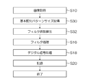
- FIG. 9 is a flowchart showing a second embodiment of the image processing method in the imaging apparatus 10-2. Note that portions common to the first embodiment of the image processing method shown in FIG. 6 are assigned the same step numbers, and detailed descriptions thereof are omitted.
- the second embodiment shown in FIG. 9 is different from the first embodiment in that the processes of steps S30 and S32 are performed instead of steps S12 and S14 of the first embodiment shown in FIG.
- step S30 the basic pattern size (M ⁇ N) (M, N: an integer of 2 or more) of the color filter array of the image sensor 18 is acquired.
- step S32 the basic pattern size (M ⁇ N) acquired in step S30 is set as a fixed pattern size (M ⁇ N), and the filter size (K ⁇ L) (K, L: M ⁇ ) larger than the fixed pattern size. Filter coefficients of K and N ⁇ L) are calculated.
- the filter coefficient of the filter size (K ⁇ L) is a filter size of K ⁇ L that assigns a weighted filter coefficient near the center and corresponds to pixels having the same positional relationship on the basic arrangement pattern of M ⁇ N pixels. The sum of the filter coefficients is calculated to be the same.
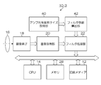
- FIG. 10 is a block diagram showing a third embodiment of the imaging apparatus according to the present invention.
- symbol is attached
- An imaging apparatus 10-3 according to the third embodiment illustrated in FIG. 10 uses an amplifier shared pixel size acquisition unit 40 and a filter coefficient calculation instead of the fixed pattern size acquisition unit 24 and the filter coefficient calculation unit 26 according to the first embodiment. The difference is that a portion 42 is provided.
- the amplifier shared pixel size acquisition unit 40 acquires the amplifier shared pixel size of the amplifier embedded in the base of the image sensor 18.
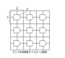
- a pixel sharing amplifier is embedded in a CMOS base.
- 2 ⁇ 2 four pixels share one amplifier A
- the amplifier shared pixel size is 2 ⁇ 2. Due to the base structure of the image sensor, the output level varies depending on the pixel position with respect to the amplifier A (upper left, upper right, lower left, and lower right positions with respect to the amplifier A), and a fixed pattern corresponding to the repetition period of the base structure is generated. appear.
- the amplifier shared pixel size acquisition unit 40 acquires the amplifier shared pixel size, and outputs size information indicating the amplifier shared pixel size to the filter coefficient calculation unit 42.
- size information indicating the amplifier shared pixel size information set in advance according to the amplifier shared pixel size of the image sensor 18 is input.
- the filter coefficient calculation unit 42 calculates a filter coefficient having a filter size larger than the amplifier shared pixel size based on the size information of the amplifier shared pixel size input from the amplifier shared pixel size acquisition unit 40, and calculates the calculated filter coefficient. This is given to the filter processing unit 22.
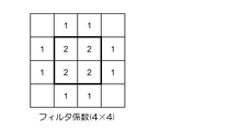
- the filter coefficient of 4 ⁇ 4 filter size is calculated for the 2 ⁇ 2 amplifier shared pixel size shown in FIG. 11A.
- the filter coefficient is assigned a weighted filter coefficient in the vicinity of the center and corresponds to a pixel having the same positional relationship on the 2 ⁇ 2 pixel of the amplifier shared pixel size, and the filter coefficient within the 4 ⁇ 4 filter size. Are set to be the same.
- the fixed pattern corresponding to the amplifier shared pixel size can be reduced by the filter processing in the filter processing unit 22 using the filter coefficient calculated by the filter coefficient calculation unit 42. Further, it is possible to prevent loss of details of the filtered image.
- FIG. 12 is a flowchart showing a third embodiment of the image processing method in the imaging apparatus 10-3. Note that portions common to the first embodiment of the image processing method shown in FIG. 6 are assigned the same step numbers, and detailed descriptions thereof are omitted.
- the third embodiment shown in FIG. 12 is different from the first embodiment in that the processes of steps S40 and S42 are performed instead of steps S12 and S14 of the first embodiment shown in FIG.
- step S40 the amplifier shared pixel size (M ⁇ N) (M, N: an integer of 2 or more) of the image sensor 18 is acquired.
- step S42 the amplifier shared pixel size (M ⁇ N) acquired in step S40 is set as a fixed pattern size (M ⁇ N), and the filter size (K ⁇ L) (K, L: M) larger than the fixed pattern size. ⁇ K, N ⁇ integer of L ⁇ L) is calculated.
- the filter coefficient of the filter size (K ⁇ L) is a K ⁇ L filter that assigns a weighted filter coefficient near the center and corresponds to pixels having the same positional relationship on the M ⁇ N pixels of the amplifier shared pixel size
- the total of the filter coefficients within the size is calculated to be the same.
- FIG. 13 is a block diagram showing a fourth embodiment of the imaging apparatus according to the present invention.
- symbol is attached
- An imaging device 10-4 according to the fourth embodiment illustrated in FIG. 13 includes a basic array pattern size acquisition unit 50, an amplifier shared pixel, instead of the fixed pattern size acquisition unit 24 and the filter coefficient calculation unit 26 according to the first embodiment. The difference is that a size acquisition unit 52, a fixed pattern size calculation unit 54, and a filter coefficient calculation unit 56 are provided.
- the basic array pattern size acquisition unit 50 and the amplifier shared pixel size acquisition unit 52 are respectively the basic array pattern size acquisition unit 30 of the second embodiment shown in FIG. 7 and the amplifier of the third embodiment shown in FIG. Similar to the shared pixel size acquisition unit 40, the basic array pattern size and the amplifier shared pixel size are acquired.
- the fixed pattern size calculation unit 54 calculates a fixed pattern size based on the basic array pattern size and the amplifier shared pixel size input from the basic array pattern size acquisition unit 50 and the amplifier shared pixel size acquisition unit 52, and calculates the fixed pattern size. Is output to the filter coefficient calculation unit 56.
- the fixed pattern size calculation unit 54 determines the sizes of these sizes in the horizontal and vertical directions. Is calculated as a fixed pattern size. This is because the fixed pattern corresponding to the basic array pattern and the fixed pattern corresponding to the amplifier shared pixel have a fixed pattern of the least common multiple of these fixed patterns.
- the number calculation unit 56 relating to the filter calculates a filter coefficient of a filter size larger than the fixed pattern size, and performs filtering processing on the calculated filter coefficient To part 22.
- the filter coefficient of the filter size of 8 ⁇ 8 is calculated for the fixed pattern size of 6 ⁇ 6. Also, the filter coefficient is assigned a weighted filter coefficient in the vicinity of the center, and is a filter coefficient within an 8 ⁇ 8 filter size corresponding to a pixel having the same positional relationship on a 6 ⁇ 6 pixel having a fixed pattern size. The total is set to be the same.
- the fixed pattern can be reduced by the filter processing in the filter processing unit 22 using the filter coefficient calculated by the filter coefficient calculation unit 56. Furthermore, according to the present embodiment, the details of the filtered image can be prevented from being lost.
- FIG. 16 is a flowchart showing a fourth embodiment of the image processing method in the imaging apparatus 10-4. Note that portions common to the first embodiment of the image processing method shown in FIG. 6 are assigned the same step numbers, and detailed descriptions thereof are omitted.
- the fourth embodiment shown in FIG. 16 is different from the first embodiment in that the processes of steps S50 to S56 are performed instead of steps S12 and S14 of the first embodiment shown in FIG.
- step S50 the basic pattern size of the color filter array of the image sensor 18 is acquired, and in step S52, the amplifier shared pixel size of the image sensor 18 is acquired.
- the least common multiple of the basic pattern size and the amplifier shared pixel size acquired in steps S50 and S52 is calculated as a fixed pattern size (M ⁇ N) (step S54).
- filter coefficients having a filter size (K ⁇ L) K, L: integer of M ⁇ K, N ⁇ L) larger than the fixed pattern size calculated in step S54 are calculated.
- the filter coefficient of the filter size (K ⁇ L) is a K ⁇ L filter that assigns a weighted filter coefficient near the center and corresponds to pixels having the same positional relationship on the M ⁇ N pixels of the amplifier shared pixel size
- the total of the filter coefficients within the size is calculated to be the same.
- FIG. 17 is a block diagram showing a fifth embodiment of the imaging apparatus according to the present invention.
- symbol is attached
- a filter size calculation unit 60 is added between the fixed pattern size acquisition unit 24 and the filter coefficient calculation unit 26 of the first embodiment. It is different in point.
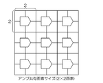
- the fixed pattern size acquisition unit 24 acquires a fixed pattern size corresponding to the repetition period of the pixel structure of the image sensor 18, and outputs size information indicating the fixed pattern size to the filter size calculation unit 60. For example, in the case of an image sensor having a color filter array including a basic array pattern of 3 ⁇ 3 pixels as shown in FIG. 18A, size information indicating a fixed pattern size of 3 ⁇ 3 is output to the filter size calculation unit 60. .
- the filter size calculation unit 60 calculates a filter size larger than the fixed pattern size based on the size information indicating the fixed pattern size input from the fixed pattern size acquisition unit 24. That is, when the fixed pattern size is M ⁇ N (M, N: an integer greater than or equal to 2) pixels, the filter size calculation unit 60 calculates the integer of K ⁇ L (K, L: M ⁇ K, N ⁇ L). ) Is calculated. In the case of a 3 ⁇ 3 pixel basic array pattern (fixed pattern size) as shown in FIG. 18A, a filter size (for example, 5 ⁇ 5) larger than 3 ⁇ 3 is calculated as shown in FIG. 18B.
- the filter coefficient calculation unit 26 calculates a filter coefficient corresponding to the filter size (K ⁇ L) input from the filter size calculation unit 60. In the example shown in FIG. 18B, 5 ⁇ 5 filter coefficients are calculated. In addition, the filter coefficient is assigned a weighted filter coefficient near the center, and is a filter coefficient within a 5 ⁇ 5 filter size corresponding to pixels having the same positional relationship on the basic arrangement pattern of 3 ⁇ 3 pixels. The total is set to be the same.
- the fixed pattern can be reduced by the filter processing in the filter processing unit 22 using the filter coefficient calculated by the filter coefficient calculation unit 26. Furthermore, details of the filtered image can be prevented from being lost.
- FIG. 19 is a flowchart showing a fifth embodiment of the image processing method in the imaging apparatus 10-5. Note that portions common to the first embodiment of the image processing method shown in FIG. 6 are assigned the same step numbers, and detailed descriptions thereof are omitted.
- the fifth embodiment shown in FIG. 19 is different from the first embodiment in that the processes of steps S60 and S62 are performed instead of step S14 of the first embodiment shown in FIG.
- step S60 based on the fixed pattern size (M ⁇ N) acquired in step S12, the filter size (K ⁇ L) (K, L: M ⁇ K, N ⁇ L larger than the fixed pattern size). Integer).
- step S62 a filter coefficient corresponding to the filter size calculated in step S60 is calculated.
- the filter coefficient of the filter size (K ⁇ L) is assigned a weighted filter coefficient in the vicinity of the center, and corresponds to pixels having the same positional relationship on the M ⁇ N pixels of the fixed pattern. The total of the filter coefficients is calculated to be the same.
- the filter coefficient is calculated by the filter coefficient calculation unit.
- the filter coefficient calculation unit When the image pickup device of the image pickup device is determined, a fixed pattern corresponding to the repetition period of the pixel structure of the image pickup device is also determined. For this reason, the filter coefficient of the filter for reducing the fixed pattern can be calculated in advance. Therefore, the filter coefficient calculated in advance may be stored in the nonvolatile memory, and the filter coefficient may be read from the nonvolatile memory during the filtering process.
- the basic arrangement pattern of the color filter to which the present invention can be applied is not limited to the three color filters of R, G, and B in the above embodiment, and the basic arrangement pattern includes at least three color filters. If it is.
- the present invention can be applied to a plurality of color filters of four or more colors, for example, filters in which E (emerald), W (white) filters, etc. are added to R, G, B.
- the size (M ⁇ N) of the basic array pattern is an integer in which M and N are 3 or more.
- CMOS image pickup device As an example of an image pickup device having a shared amplifier for each predetermined pixel group, a CMOS image pickup device has been described. However, the present invention is not limited to a CMOS image pickup device, but is applied to a MOS type or XY address type image pickup device. Is also applicable.
- the imaging apparatus having the image processing apparatus including the fixed pattern reduction process has been described.
- the image processing including the fixed pattern reduction process may be performed by an external image processing apparatus.
- the imaging apparatus records a mosaic image (RAW data) that has not been subjected to image processing, and performs fixed pattern reduction processing according to the present invention when the RAW data is RAW developed by an external image processing apparatus. It may be.
- the image processing program including the fixed pattern reduction processing according to the present invention and the recording medium on which the image processing program is recorded may be incorporated into RAW development software dedicated to the imaging apparatus.
Landscapes
- Engineering & Computer Science (AREA)
- Physics & Mathematics (AREA)
- General Physics & Mathematics (AREA)
- Theoretical Computer Science (AREA)
- Multimedia (AREA)
- Signal Processing (AREA)
- Color Television Image Signal Generators (AREA)
- Image Processing (AREA)
- Transforming Light Signals Into Electric Signals (AREA)
- Facsimile Image Signal Circuits (AREA)
- Studio Devices (AREA)
Abstract
Description
<第1の実施形態>
図1Aは、光電変換素子が2次元配列された撮像素子の各光電変換素子上に配置されたモザイク状のカラーフィルタ配列の一例を示す。
図3は、撮像素子に配置されたモザイク状のカラーフィルタ配列の他の例と、これに対応する固定パターン低減用のフィルタのフィルタ係数の一例を示す図である。
図5は本発明に係る撮像装置の第1の実施形態を示すブロック図である。
図6は上記撮像装置10-1における画像処理方法の第1の実施形態を示すフローチャートである。
M<K<M×2.5,N<L<N×2.5 …(2)
続いて、フィルタ処理部22は、ステップS10で取得したモザイク画像と、ステップS14で算出されたフィルタ係数とに基づいてフィルタ処理を行う(ステップS16)。
図7は本発明に係る撮像装置の第2の実施形態を示すブロック図である。尚、図5に示した第1の実施形態と共通する部分には、同一の符号を付し、その詳細な説明は省略する。
図9は上記撮像装置10-2における画像処理方法の第2の実施形態を示すフローチャートである。尚、図6に示した画像処理方法の第1の実施形態と共通する部分には、同一のステップ番号を付し、その詳細な説明は省略する。
図10は本発明に係る撮像装置の第3の実施形態を示すブロック図である。尚、図5に示した第1の実施形態と共通する部分には、同一の符号を付し、その詳細な説明は省略する。
図12は上記撮像装置10-3における画像処理方法の第3の実施形態を示すフローチャートである。尚、図6に示した画像処理方法の第1の実施形態と共通する部分には、同一のステップ番号を付し、その詳細な説明は省略する。
図13は本発明に係る撮像装置の第4の実施形態を示すブロック図である。尚、図5に示した第1の実施形態と共通する部分には、同一の符号を付し、その詳細な説明は省略する。
図16は上記撮像装置10-4における画像処理方法の第4の実施形態を示すフローチャートである。尚、図6に示した画像処理方法の第1の実施形態と共通する部分には、同一のステップ番号を付し、その詳細な説明は省略する。
図17は本発明に係る撮像装置の第5の実施形態を示すブロック図である。尚、図5に示した第1の実施形態と共通する部分には、同一の符号を付し、その詳細な説明は省略する。
図19は上記撮像装置10-5における画像処理方法の第5の実施形態を示すフローチャートである。尚、図6に示した画像処理方法の第1の実施形態と共通する部分には、同一のステップ番号を付し、その詳細な説明は省略する。
上記実施形態では、フィルタ係数算出部によりフィルタ係数を算出している。なお、撮像装置の撮像素子が決定すると、その撮像素子の画素構造の繰り返し周期に対応する固定パターンも決定する。このため、その固定パターンを低減するためのフィルタのフィルタ係数を予め算出することができる。したがって、予め算出したフィルタ係数を不揮発性メモリに記憶させておき、フィルタ処理時に不揮発性メモリからフィルタ係数を読み出すようにしてもよい。
Claims (15)
- M×N(M、N:2以上の整数)画素の繰り返し周期の画素構造を有する撮像素子を含む撮像手段により撮影された画像を取得する画像取得手段と、
K×L(K,L:M<K,N<Lの整数)のフィルタサイズのフィルタを有し、該フィルタに設定されたフィルタ係数と、前記画像取得手段により取得した画像中の注目画素を基準にして抽出されるK×L画素の画素値とを畳み込み演算して前記注目画素の画素値を算出するフィルタ処理手段とを備え、
前記フィルタに設定されるフィルタ係数は、前記フィルタの中央付近に重み付けされており、かつ前記M×N画素の画素構造上で同じ位置関係にある画素に対応する、前記フィルタサイズ内のフィルタ係数の合計が、全て同一になるように設定されている画像処理装置。 - 前記撮像素子は、水平方向及び垂直方向に配列された複数の画素上に3色のカラーフィルタを含む所定の基本配列パターンが、水平方向及び垂直方向に繰り返して配置されたカラー撮像素子であり、
前記M×N画素の繰り返し周期の画素構造は、前記所定の基本配列パターンに対応するものである請求項1に記載の画像処理装置。 - 前記撮像素子は、所定の画素群毎にアンプを共有する素子構造を有する撮像素子であり、
前記M×N画素の繰り返し周期の画素構造は、前記所定の画素群に対応するものである請求項1に記載の画像処理装置。 - 前記撮像素子は、水平方向及び垂直方向に配列された複数の画素上に3色のカラーフィルタを含む所定の基本配列パターンが、水平方向及び垂直方向に繰り返して配置され、かつ所定の画素群毎にアンプを共有する素子構造を有するカラー撮像素子であり、
前記M×N画素の繰り返し周期の画素構造は、前記所定の基本配列パターンと前記所定の画素群との最小公倍数の周期となるものである請求項1に記載の画像処理装置。 - 前記基本配列パターンは、赤(R)、緑(G)、青(B)の3原色のカラーフィルタを含み、前記基本配列パターンは、N×N(N:3以上の整数)画素に対応する正方配列パターンである請求項2又は4に記載の画像処理装置。
- 前記フィルタ処理手段は、前記フィルタによる処理対象領域のK×L画素中の注目画素と、該注目画素のカラーフィルタと同じ色のカラーフィルタに対応する画素の画素値と、これらの画素に対応する前記フィルタのフィルタ係数との畳み込み演算により前記注目画素の画素値を算出する請求項2、4又は5に記載の画像処理装置。
- 前記撮像素子の画素構造の繰り返し周期であるM×N画素に対応する固定パターンサイズを取得する固定パターンサイズ取得手段と、
前記取得した固定パターンサイズに基づいて前記フィルタの中央付近に重み付けされたフィルタ係数を有し、かつ前記M×N画素の素子構造上で同じ位置関係にある画素に対応する、前記フィルタサイズ内のフィルタ係数の合計が、全て同一になるように前記フィルタ係数を算出するフィルタ係数算出手段とを更に備え、
前記フィルタ処理手段は、前記フィルタ係数算出手段により前記算出されたフィルタ係数を取得する請求項1に記載の画像処理装置。 - 前記撮像素子は、水平方向及び垂直方向に配列された複数の画素上に3色のカラーフィルタを含む所定の基本配列パターンが、水平方向及び垂直方向に繰り返して配置されたカラー撮像素子であり、
前記固定パターンサイズ取得手段は、前記所定の基本配列パターンのサイズを前記固定パターンサイズとして取得する請求項7に記載の画像処理装置。 - 前記撮像素子は、所定の画素群毎にアンプを共有する素子構造を有する撮像素子であり、
前記固定パターンサイズ取得手段は、前記アンプを共有する所定の画素群の画像サイズを前記固定パターンサイズとして取得する請求項7に記載の画像処理装置。 - 前記撮像素子は、水平方向及び垂直方向に配列された複数の画素上に3色のカラーフィルタを含む所定の基本配列パターンが、水平方向及び垂直方向に繰り返して配置され、かつ所定の画素群毎にアンプを共有する素子構造を有するカラー撮像素子であり、
前記固定パターンサイズ取得手段は、前記所定の基本配列パターンのサイズと前記アンプを共有する所定の画素群の画像サイズとの最小公倍数となるサイズを前記固定パターンサイズとして取得する請求項7に記載の画像処理装置。 - 前記M×Nの固定パターンサイズに基づいて前記K×Lのフィルタサイズを算出するフィルタサイズ算出手段を備え、
前記フィルタ係数算出手段は、前記フィルタサイズ算出手段により算出されたフィルタサイズに応じたフィルタ係数を算出する請求項7に記載の画像処理装置。 - M×N(M、N:2以上の整数)画素の繰り返し周期の画素構造を有する撮像素子を含む撮像手段により撮影された画像を取得する工程と、
(a)前記取得した画像内で注目画素を設定し、該注目画素を基準にしてK×L(K,L:M<K,N<Lの整数)画素を抽出する工程と、
(b)K×Lのフィルタサイズのフィルタを有し、該フィルタに設定されたフィルタ係数と、前記抽出したK×L画素の画素値とを畳み込み演算して前記注目画素の画素値を算出する工程と、
(c)前記取得した画像に対して前記注目画素を1画素ずつ移動させながら前記工程(a)及び工程(b)を繰り返し実行する工程とを含み、
前記フィルタに設定されるフィルタ係数は、前記フィルタの中央付近に重み付けされており、かつ前記M×N画素の素子構造上で同じ位置関係にある画素に対応する、前記フィルタサイズ内のフィルタ係数の合計が、全て同一になるように設定されている画像処理方法。 - M×N(M、N:2以上の整数)画素の繰り返し周期の画素構造を有する撮像素子を含む撮像手段により撮影された画像を取得する機能と、
(a)前記取得した画像内で注目画素を設定し、該注目画素を基準にしてK×L(K,L:M<K,N<Lの整数)画素を抽出する機能と、
(b)K×Lのフィルタサイズのフィルタを有し、該フィルタに設定されたフィルタ係数と、前記抽出したK×L画素の画素値とを畳み込み演算して前記注目画素の画素値を算出する機能と、
(c)前記取得した画像に対して前記注目画素を1画素ずつ移動させながら前記機能(a)及び機能(b)を繰り返し実行する機能と、をコンピュータに実行させ、
前記フィルタに設定されるフィルタ係数は、前記フィルタの中央付近に重み付けされており、かつ前記M×N画素の素子構造上で同じ位置関係にある画素に対応する、前記フィルタサイズ内のフィルタ係数の合計が、全て同一になるように設定されている画像処理プログラム。 - コンピュータ読取可能な非一次的な記録媒体であって、該記録媒体に格納された指令がプロセッサによって読み取られて実行されると、前記プロセッサが、
M×N(M、N:2以上の整数)画素の繰り返し周期の画素構造を有する撮像素子を含む撮像手段により撮影された画像を取得する工程と、
(a)前記取得した画像内で注目画素を設定し、該注目画素を基準にしてK×L(K,L:M<K,N<Lの整数)画素を抽出する工程と、
(b)K×Lのフィルタサイズのフィルタを有し、該フィルタに設定されたフィルタ係数と、前記抽出したK×L画素の画素値とを畳み込み演算して前記注目画素の画素値を算出する工程と、
(c)前記取得した画像に対して前記注目画素を1画素ずつ移動させながら前記工程(a)及び工程(b)を繰り返し実行する工程とを実行するように構成されており、
前記フィルタに設定されるフィルタ係数は、前記フィルタの中央付近に重み付けされており、かつ前記M×N画素の素子構造上で同じ位置関係にある画素に対応する、前記フィルタサイズ内のフィルタ係数の合計が、全て同一になるように設定されている、記録媒体。 - 撮影光学系と該撮影光学系を介して被写体像が結像される撮像素子とを含む撮像手段と、
前記撮像手段から出力される画像を取得する前記画像画取得手段と、
請求項1から11のいずれか1項に記載の画像処理装置と、
を備える撮像装置。
Priority Applications (5)
| Application Number | Priority Date | Filing Date | Title |
|---|---|---|---|
| BR112014004533A BR112014004533A2 (pt) | 2011-09-29 | 2012-06-21 | dispositivo de processamento de imagem e método, e dispositivo de imagem |
| JP2013535990A JP5519083B2 (ja) | 2011-09-29 | 2012-06-21 | 画像処理装置、方法、プログラムおよび撮像装置 |
| CN201280026611.2A CN103563361B (zh) | 2011-09-29 | 2012-06-21 | 图像处理设备和方法以及成像设备 |
| EP12836425.4A EP2763417B1 (en) | 2011-09-29 | 2012-06-21 | Device, method and program for image processing, recording medium, and imaging device |
| US14/163,782 US8817141B2 (en) | 2011-09-29 | 2014-01-24 | Image processing device and method, recording medium, and imaging device |
Applications Claiming Priority (2)
| Application Number | Priority Date | Filing Date | Title |
|---|---|---|---|
| JP2011-215057 | 2011-09-29 | ||
| JP2011215057 | 2011-09-29 |
Related Child Applications (1)
| Application Number | Title | Priority Date | Filing Date |
|---|---|---|---|
| US14/163,782 Continuation US8817141B2 (en) | 2011-09-29 | 2014-01-24 | Image processing device and method, recording medium, and imaging device |
Publications (1)
| Publication Number | Publication Date |
|---|---|
| WO2013046828A1 true WO2013046828A1 (ja) | 2013-04-04 |
Family
ID=47994890
Family Applications (1)
| Application Number | Title | Priority Date | Filing Date |
|---|---|---|---|
| PCT/JP2012/065837 Ceased WO2013046828A1 (ja) | 2011-09-29 | 2012-06-21 | 画像処理装置、方法、プログラムおよび記録媒体並びに撮像装置 |
Country Status (6)
| Country | Link |
|---|---|
| US (1) | US8817141B2 (ja) |
| EP (1) | EP2763417B1 (ja) |
| JP (1) | JP5519083B2 (ja) |
| CN (1) | CN103563361B (ja) |
| BR (1) | BR112014004533A2 (ja) |
| WO (1) | WO2013046828A1 (ja) |
Families Citing this family (15)
| Publication number | Priority date | Publication date | Assignee | Title |
|---|---|---|---|---|
| KR101503227B1 (ko) | 2007-04-11 | 2015-03-16 | 레드.컴 인코포레이티드 | 비디오 카메라 |
| US8237830B2 (en) | 2007-04-11 | 2012-08-07 | Red.Com, Inc. | Video camera |
| JPWO2013084406A1 (ja) * | 2011-12-08 | 2015-04-27 | パナソニックIpマネジメント株式会社 | 固体撮像装置及び撮像装置 |
| JP5600812B2 (ja) * | 2011-12-28 | 2014-10-01 | 富士フイルム株式会社 | 撮像装置 |
| JP2016508700A (ja) * | 2013-02-14 | 2016-03-22 | レッド.コム,インコーポレイテッド | ビデオカメラ |
| JP6729394B2 (ja) * | 2015-01-13 | 2020-07-22 | ソニー株式会社 | 画像処理装置、画像処理方法、プログラム及びシステム |
| CN106454054B (zh) | 2016-11-29 | 2019-03-19 | Oppo广东移动通信有限公司 | 控制方法、控制装置及电子装置 |
| CN106504218B (zh) | 2016-11-29 | 2019-03-12 | Oppo广东移动通信有限公司 | 控制方法、控制装置及电子装置 |
| CN106604001B (zh) * | 2016-11-29 | 2018-06-29 | 广东欧珀移动通信有限公司 | 图像处理方法、图像处理装置、成像装置及电子装置 |
| CN106507068B (zh) | 2016-11-29 | 2018-05-04 | 广东欧珀移动通信有限公司 | 图像处理方法及装置、控制方法及装置、成像及电子装置 |
| CN106454288B (zh) * | 2016-11-29 | 2018-01-19 | 广东欧珀移动通信有限公司 | 控制方法、控制装置、成像装置及电子装置 |
| CN106341670B (zh) | 2016-11-29 | 2017-09-22 | 广东欧珀移动通信有限公司 | 控制方法、控制装置及电子装置 |
| WO2019010233A1 (en) | 2017-07-05 | 2019-01-10 | Red. Com, Llc | PROCESSING VIDEO IMAGE DATA IN ELECTRONIC DEVICES |
| CN110365923A (zh) * | 2018-04-09 | 2019-10-22 | 印象认知(北京)科技有限公司 | 一种图像传感器 |
| CN112492162B (zh) * | 2020-11-30 | 2022-04-01 | 维沃移动通信有限公司 | 图像传感器、摄像模组和电子设备 |
Citations (5)
| Publication number | Priority date | Publication date | Assignee | Title |
|---|---|---|---|---|
| JP2000184386A (ja) * | 1998-01-08 | 2000-06-30 | Fuji Photo Film Co Ltd | 固体撮像装置および信号処理方法 |
| JP2005130241A (ja) * | 2003-10-24 | 2005-05-19 | Matsushita Electric Ind Co Ltd | 画像信号処理装置及び画像信号処理方法 |
| JP2005136766A (ja) * | 2003-10-31 | 2005-05-26 | Sony Corp | 画像処理装置および画像処理方法 |
| JP2005167896A (ja) * | 2003-12-05 | 2005-06-23 | Matsushita Electric Ind Co Ltd | 画像信号処理装置及び画像信号処理方法 |
| JP2007036765A (ja) * | 2005-07-28 | 2007-02-08 | Sony Corp | 画像処理装置、画像処理方法および撮像装置 |
Family Cites Families (11)
| Publication number | Priority date | Publication date | Assignee | Title |
|---|---|---|---|---|
| US6882364B1 (en) | 1997-12-02 | 2005-04-19 | Fuji Photo Film Co., Ltd | Solid-state imaging apparatus and signal processing method for transforming image signals output from a honeycomb arrangement to high quality video signals |
| US6222641B1 (en) | 1998-07-01 | 2001-04-24 | Electronics For Imaging, Inc. | Method and apparatus for image descreening |
| JP2001148797A (ja) | 1999-11-19 | 2001-05-29 | Canon Inc | 画像信号処理装置及び方法 |
| JP4139587B2 (ja) * | 2001-12-13 | 2008-08-27 | 大日本印刷株式会社 | 単板式カラーディジタルカメラにおける撮像画像の補間装置および方法 |
| US20060119724A1 (en) | 2004-12-02 | 2006-06-08 | Fuji Photo Film Co., Ltd. | Imaging device, signal processing method on solid-state imaging element, digital camera and controlling method therefor and color image data generating method |
| DE102006038646B4 (de) * | 2006-08-17 | 2011-03-24 | Baumer Optronic Gmbh | Bildverarbeitungsvorrichtung für Farb-Bilddaten |
| WO2008067472A2 (en) * | 2006-11-29 | 2008-06-05 | President And Fellows Of Harvard College | A new spatio-spectral sampling paradigm for imaging and a novel color filter array design |
| JP2010239492A (ja) | 2009-03-31 | 2010-10-21 | Olympus Corp | 撮像装置および映像信号のノイズ低減方法 |
| JP2011171885A (ja) * | 2010-02-17 | 2011-09-01 | Renesas Electronics Corp | 画像処理装置及び画像処理方法 |
| JP5054857B1 (ja) | 2011-02-28 | 2012-10-24 | 富士フイルム株式会社 | カラー撮像装置 |
| JP5378627B2 (ja) * | 2011-03-11 | 2013-12-25 | 富士フイルム株式会社 | 撮像装置およびその動作制御方法ならびに撮像システム |
-
2012
- 2012-06-21 BR BR112014004533A patent/BR112014004533A2/pt not_active IP Right Cessation
- 2012-06-21 WO PCT/JP2012/065837 patent/WO2013046828A1/ja not_active Ceased
- 2012-06-21 CN CN201280026611.2A patent/CN103563361B/zh active Active
- 2012-06-21 EP EP12836425.4A patent/EP2763417B1/en active Active
- 2012-06-21 JP JP2013535990A patent/JP5519083B2/ja active Active
-
2014
- 2014-01-24 US US14/163,782 patent/US8817141B2/en active Active
Patent Citations (5)
| Publication number | Priority date | Publication date | Assignee | Title |
|---|---|---|---|---|
| JP2000184386A (ja) * | 1998-01-08 | 2000-06-30 | Fuji Photo Film Co Ltd | 固体撮像装置および信号処理方法 |
| JP2005130241A (ja) * | 2003-10-24 | 2005-05-19 | Matsushita Electric Ind Co Ltd | 画像信号処理装置及び画像信号処理方法 |
| JP2005136766A (ja) * | 2003-10-31 | 2005-05-26 | Sony Corp | 画像処理装置および画像処理方法 |
| JP2005167896A (ja) * | 2003-12-05 | 2005-06-23 | Matsushita Electric Ind Co Ltd | 画像信号処理装置及び画像信号処理方法 |
| JP2007036765A (ja) * | 2005-07-28 | 2007-02-08 | Sony Corp | 画像処理装置、画像処理方法および撮像装置 |
Non-Patent Citations (1)
| Title |
|---|
| See also references of EP2763417A4 * |
Also Published As
| Publication number | Publication date |
|---|---|
| JPWO2013046828A1 (ja) | 2015-03-26 |
| US20140139709A1 (en) | 2014-05-22 |
| CN103563361A (zh) | 2014-02-05 |
| US8817141B2 (en) | 2014-08-26 |
| EP2763417A4 (en) | 2015-08-19 |
| BR112014004533A2 (pt) | 2017-03-28 |
| JP5519083B2 (ja) | 2014-06-11 |
| EP2763417A1 (en) | 2014-08-06 |
| CN103563361B (zh) | 2015-04-29 |
| EP2763417B1 (en) | 2019-02-27 |
Similar Documents
| Publication | Publication Date | Title |
|---|---|---|
| JP5519083B2 (ja) | 画像処理装置、方法、プログラムおよび撮像装置 | |
| JP5872408B2 (ja) | カラー撮像装置及び画像処理方法 | |
| WO2012117583A1 (ja) | カラー撮像装置 | |
| WO2012117616A1 (ja) | 撮像装置及び欠陥画素補正方法 | |
| JP5597777B2 (ja) | カラー撮像素子及び撮像装置 | |
| JP4905279B2 (ja) | 撮像回路および撮像装置 | |
| JP4305071B2 (ja) | 信号補正方法 | |
| JP5600813B2 (ja) | 画像処理装置及び撮像装置 | |
| WO2012147515A1 (ja) | 撮像装置及び撮像方法 | |
| JP5607265B2 (ja) | 撮像装置、撮像装置の制御方法、及び制御プログラム | |
| JPH09238355A (ja) | 撮像デバイスのラインノイズ除去方法及びそれを用いたラインノイズ除去装置 | |
| JP5411390B2 (ja) | カラー撮像素子 | |
| JP5607266B2 (ja) | 撮像装置、撮像装置の制御方法、及び制御プログラム | |
| WO2013001869A1 (ja) | 撮像装置及び撮像プログラム | |
| JP4270892B2 (ja) | 偽色低減装置 | |
| JP5624228B2 (ja) | 撮像装置、撮像装置の制御方法、及び制御プログラム | |
| JP5363966B2 (ja) | 撮像装置 | |
| JP5607267B2 (ja) | 撮像装置、撮像装置の制御方法、及び制御プログラム | |
| JP2012227869A (ja) | 画像処理装置及び画像処理方法並びにデジタルカメラ | |
| WO2013100095A1 (ja) | 撮像装置、撮像装置の制御方法、及び制御プログラム |
Legal Events
| Date | Code | Title | Description |
|---|---|---|---|
| 121 | Ep: the epo has been informed by wipo that ep was designated in this application |
Ref document number: 12836425 Country of ref document: EP Kind code of ref document: A1 |
|
| ENP | Entry into the national phase |
Ref document number: 2013535990 Country of ref document: JP Kind code of ref document: A |
|
| WWE | Wipo information: entry into national phase |
Ref document number: 2012836425 Country of ref document: EP |
|
| NENP | Non-entry into the national phase |
Ref country code: DE |
|
| REG | Reference to national code |
Ref country code: BR Ref legal event code: B01A Ref document number: 112014004533 Country of ref document: BR |
|
| ENP | Entry into the national phase |
Ref document number: 112014004533 Country of ref document: BR Kind code of ref document: A2 Effective date: 20140226 |