WO2013046884A1 - Procédé d'impression et dispositif d'impression - Google Patents
Procédé d'impression et dispositif d'impression Download PDFInfo
- Publication number
- WO2013046884A1 WO2013046884A1 PCT/JP2012/068443 JP2012068443W WO2013046884A1 WO 2013046884 A1 WO2013046884 A1 WO 2013046884A1 JP 2012068443 W JP2012068443 W JP 2012068443W WO 2013046884 A1 WO2013046884 A1 WO 2013046884A1
- Authority
- WO
- WIPO (PCT)
- Prior art keywords
- ink
- flocculant
- printing
- printing material
- supply device
- Prior art date
- Legal status (The legal status is an assumption and is not a legal conclusion. Google has not performed a legal analysis and makes no representation as to the accuracy of the status listed.)
- Ceased
Links
Images




Classifications
-
- B—PERFORMING OPERATIONS; TRANSPORTING
- B41—PRINTING; LINING MACHINES; TYPEWRITERS; STAMPS
- B41M—PRINTING, DUPLICATING, MARKING, OR COPYING PROCESSES; COLOUR PRINTING
- B41M7/00—After-treatment of prints, e.g. heating, irradiating, setting of the ink, protection of the printed stock
- B41M7/0018—After-treatment of prints, e.g. heating, irradiating, setting of the ink, protection of the printed stock using ink-fixing material, e.g. mordant, precipitating agent, after printing, e.g. by ink-jet printing, coating or spraying
-
- B—PERFORMING OPERATIONS; TRANSPORTING
- B41—PRINTING; LINING MACHINES; TYPEWRITERS; STAMPS
- B41J—TYPEWRITERS; SELECTIVE PRINTING MECHANISMS, i.e. MECHANISMS PRINTING OTHERWISE THAN FROM A FORME; CORRECTION OF TYPOGRAPHICAL ERRORS
- B41J11/00—Devices or arrangements of selective printing mechanisms, e.g. ink-jet printers or thermal printers, for supporting or handling copy material in sheet or web form
- B41J11/0015—Devices or arrangements of selective printing mechanisms, e.g. ink-jet printers or thermal printers, for supporting or handling copy material in sheet or web form for treating before, during or after printing or for uniform coating or laminating the copy material before or after printing
-
- B—PERFORMING OPERATIONS; TRANSPORTING
- B41—PRINTING; LINING MACHINES; TYPEWRITERS; STAMPS
- B41J—TYPEWRITERS; SELECTIVE PRINTING MECHANISMS, i.e. MECHANISMS PRINTING OTHERWISE THAN FROM A FORME; CORRECTION OF TYPOGRAPHICAL ERRORS
- B41J3/00—Typewriters or selective printing or marking mechanisms characterised by the purpose for which they are constructed
- B41J3/407—Typewriters or selective printing or marking mechanisms characterised by the purpose for which they are constructed for marking on special material
- B41J3/4078—Printing on textile
-
- B—PERFORMING OPERATIONS; TRANSPORTING
- B41—PRINTING; LINING MACHINES; TYPEWRITERS; STAMPS
- B41M—PRINTING, DUPLICATING, MARKING, OR COPYING PROCESSES; COLOUR PRINTING
- B41M5/00—Duplicating or marking methods; Sheet materials for use therein
- B41M5/0011—Pre-treatment or treatment during printing of the recording material, e.g. heating, irradiating
- B41M5/0017—Application of ink-fixing material, e.g. mordant, precipitating agent, on the substrate prior to printing, e.g. by ink-jet printing, coating or spraying
-
- D—TEXTILES; PAPER
- D06—TREATMENT OF TEXTILES OR THE LIKE; LAUNDERING; FLEXIBLE MATERIALS NOT OTHERWISE PROVIDED FOR
- D06P—DYEING OR PRINTING TEXTILES; DYEING LEATHER, FURS OR SOLID MACROMOLECULAR SUBSTANCES IN ANY FORM
- D06P5/00—Other features in dyeing or printing textiles, or dyeing leather, furs, or solid macromolecular substances in any form
- D06P5/30—Ink jet printing
Definitions
- the present invention relates to a printing method and a printing apparatus, and more particularly, to a method and an apparatus for printing on an object to be printed including regions having different fiber densities by an inkjet method.
- Inkjet systems are widely used because they can print at high speed with a simple mechanism, and printing has been attempted not only on paper but also on various objects to be printed such as cloth, woven fabric, and smooth resin surface.
- the forms and materials of these printed materials have been diversified, and it is difficult to print the printed materials uniformly.
- a fabric composed of plain weave or twill weave is a substrate, there are regions where the fiber density of the yarn is different depending on the crossing frequency of warp and weft. Further, regions having different fiber densities are also generated due to differences in yarn tension or the like when weaving the yarn.
- the ink ejected onto the regions having different fiber densities has a thickness direction of the printing material at a permeation speed according to the size of the gap between the fibers, that is, the fiber density. Penetrated into.
- L 2 d ⁇ ⁇ ⁇ t ⁇ cos ⁇ / 4 ⁇ (1)
- L is the permeation distance
- d is the gap size between the fibers
- ⁇ is the surface tension
- t the time
- ⁇ is the contact angle indicating the wettability between the ink and the fibers
- ⁇ is the viscosity of the ink.
- the permeation as shown in the formula (1) stops, but the ink moves due to the difference in capillary force. That is, due to the difference in fiber density or contact angle with the ink between adjacent regions, a capillary force is generated for the ink that has penetrated into the gap between the fibers.
- the capillary force is a force acting on the ink, and when the wettability is large or the interfiber distance is small, the capillary force is large, and when the wettability is small or the interfiber distance is large, the capillary force is small.
- the capillary force acts from the surrounding area where the fiber density is high, so that the ink is moved to the area where the capillary force is high.
- the contact angle with the ink is the same, so the ink moves to an area where the fiber density is high.
- the final landing position of the ink on the printed material is different in the thickness direction of the printed material and in the direction along the printed material due to the difference in fiber density, which hinders uniform color development. ing.
- the difference in the partial capillary force of the fabric can be detected as, for example, a difference in the permeation speed of ink when ink droplets are supplied to a portion of the fabric.
- the ink After the ink droplets are supplied, the ink begins to permeate in the thickness direction of the fiber, but it can be observed that the permeation speed is high in a region having a low void density and many voids. Also, if the fabric is completely immersed in the ink, and then pulled up and squeezed (the amount of the liquid is squeezed with a roller, etc.), the ink will be contained uniformly immediately after the squeeze, and color unevenness cannot be detected, but time elapsed with drying. At the same time, ink movement occurs, and it is observed that the ink density in the region with high fiber density, that is, the region with high capillary force, becomes high.
- ink is ejected onto a substrate to be printed that has been previously immersed in an acidic solution. It has been proposed to suppress bleeding by agglomeration.
- Patent Document 1 in order to instantaneously agglomerate the ink that has landed on the printed material, a permeation-inhibiting film is formed on the surface of the printed material. It will be difficult to penetrate and will remain liquid. When the amount of printing is small, it is possible to print uniformly on the surface of the object to be printed. However, when the amount of printing increases, ink flows to the periphery, and uneven printing tends to occur. In particular, ink penetration is liable to occur in a region where the fiber density is high. In addition, since a coherent layer is formed on the surface of the printing material, it is difficult to print evenly in the thread in the thickness direction of the printing material.
- the present invention has been made in order to solve such a conventional problem, and provides a printing method and a printing apparatus capable of uniformly printing the inside of an object to be printed including regions having different fiber densities. With the goal.
- a printing method is a printing method for performing printing by ejecting ink onto an object to be printed including regions having different fiber densities by the ink jet method, and performing ink ejection by the ink jet method.
- a first aggregating agent for raising the ink to a predetermined viscosity is supplied to the printing material in advance, and ink is ejected onto the printing material by an inkjet method, and then the second aggregating agent is applied to the printing material.
- the ink whose viscosity is increased to a predetermined viscosity by the first aggregating agent and whose movement speed is suppressed is fixed in the printing medium, and the movement of the ink due to the capillary force is stopped.
- the total amount of the first flocculant and the second flocculant supplied is determined by the fact that the flocculant in the ink ejected onto the printing material is the first flocculant and the second flocculant. It is preferable to set so as to exceed the isoelectric point by reacting with the agent. That is, sufficient coagulant is supplied so that the coagulant in all inks aggregates. Further, the distance at which the ink penetrates into the printing material can be controlled by the supply amount of the first flocculant.
- the first aggregating agent is preferably set so that the movement of the ink whose viscosity has increased when the ink has permeated the thread constituting the printing material by a predetermined distance is suppressed.
- the first flocculant can be supplied by an ink jet method or a dip method.
- the second flocculant can be supplied by an ink jet method or an air spray method.
- a cationic material can be used for the first flocculant and the second flocculant.
- an anionic material can be used for the first flocculant and the second flocculant.
- the printed material is made of a material composed of fibers such as a woven fabric or a knitted fabric or a nonwoven fabric composed of a plurality of fibers, and has regions where the crossing frequencies of the yarns are different.
- the printing apparatus is a printing apparatus that performs printing by ejecting ink onto an object to be printed including regions having different fiber densities by the ink jet method, and applies the ink ejected by the ink jet method to a predetermined amount.
- a first flocculant supply device that supplies a first flocculant for increasing the viscosity to the printed material in advance, and a printed material to which the first flocculant is supplied by the first flocculant supply device
- a second flocculant supply device that supplies the printed material and a fixing device that fixes the ink fixed in the printed material to the printed material.
- the second aggregating agent is supplied and the printing material is printed. Since the ink in the product is fixed, it is possible to print evenly to the inside of the printing material including regions having different fiber densities. Even in the case where the amount of printing is large and the permeation inhibition layer is formed by the first aggregating agent and the ink with insufficient agglomeration reaction is left, the unaggregated ink is completely removed by the second aggregating agent. Uniform printing is possible because it is agglomerated and cannot move.
- FIG. 6 is a cross-sectional view showing a printed material used in a modification of the first embodiment.
- FIG. 10 is a diagram illustrating a printed material that is printed according to a modification of the first embodiment. It is a figure which shows the coagulant supply apparatus which supplies the coagulant
- FIG. 6 is a cross-sectional view showing a printing object printed in a second embodiment. It is a block diagram which shows the modification of the printing apparatus which performs the printing method which concerns on Embodiment 1 and 2.
- FIG. 6 is a diagram illustrating a configuration of a printing apparatus that performs a printing method according to a third embodiment.
- FIG. 1 shows the configuration of a printing apparatus that performs a printing method according to Embodiment 1 of the present invention.
- the printing apparatus includes a first flocculant supply device 1 that supplies the flocculant A for increasing the ink ejected by the ink jet method to a predetermined viscosity in advance to the printing material P, and the ink to be printed by the ink jet method.
- the ink supply device 2 for ejecting droplets onto the product P and the coagulant B for fixing the ink that has penetrated into the print product P and has been increased to a predetermined viscosity by the coagulant A are supplied to the print product P.
- a second flocculant supply device 3 and a fixing device 4 for fixing the ink fixed in the printing material P to the printing material P are provided.
- the printed material P is a fiber such as a synthetic fiber such as polyester, nylon, acrylic, or the like, a cloth woven with animal or vegetable fibers such as cotton, wool, silk, or a knitted knitted fabric. Those having regions with different densities are used.
- the first flocculant supply device 1 supplies the flocculant A so as to penetrate into the inside of the yarn of the printing material P.
- the flocculant A is composed of the same components as the flocculant B, and is adjusted to a concentration lower than that of the flocculant B.
- the ink ejected from the ink supply device 2 onto the printing material P penetrates about the thickness distance of the thread. At this point, the ink density is adjusted to increase the ink to a predetermined viscosity. In this way, the ink moving speed can be reduced by increasing the ink to a predetermined viscosity, and until the ink penetrates to the thickness distance of the thread of the printing material P and is fixed by the flocculant B.
- the ink does not diffuse in the direction along the substrate P due to the surrounding capillary force, that is, the movement of the ink is within a certain range (e.g., the landing position pitch of ink that is sequentially ejected from the ink supply device 2 or
- the predetermined viscosity is set so as to remain within the range of the thickness of the thread constituting the printed matter.
- the supply amount of the flocculant A is such that the material to be printed P, the thickness of the thread, the type of ink, the supply amount of the ink, etc., so that the ink has a predetermined viscosity when it penetrates to the thickness of the thread. Is set based on
- the ink supply device 2 is arranged on the downstream side of the first flocculant supply device 1 with respect to the moving direction of the printing material P, and ink is applied to the printing material P supplied with the flocculant A by an ink jet method. Do drops.
- the ink to be ejected contains an aggregating agent, and the aggregating agent performs an aggregating reaction with the aggregating agents A and B.
- a part of the aggregating agent is agglomerated with the aggregating agent A having a low concentration supplied in advance, and the remaining aggregating agent is agglomerated with the aggregating agent B.
- the ink supply amount is set based on a print image printed on the printing material P or the like.
- the dye contained in the ink is selected according to the material of the printing material P.
- a disperse dye is used, and the printing material P is a plant such as cotton.
- a reactive dye can be used when it is made of fibers, and an acid dye can be used when the printing material P is made of nylon and animal fibers (such as hair or silk).
- the second flocculant supply device 3 is arranged on the downstream side of the ink supply device 2 with respect to the moving direction of the printing material P, and supplies the flocculant B to the printing material P on which ink has been deposited. .
- the flocculant B is adjusted so as to fix the movement of the ink on the printing material P. That is, the aggregate amount of the flocculants A and B is supplied so that the charge of the flocculant exceeds the isoelectric point due to the flocculant A and the flocculant B following the flocculant A.
- the flocculant B is set and supplied in an amount equal to or greater than the sum of the amount of flocculant B minus the amount of flocculant B supplied.
- the sum total of the supply amount of the flocculants A and B that is greater than or equal to the amount exceeding the isoelectric point of the flocculant can be determined based on measurement results such as electrophoresis and colloidal particle aggregation measurement.
- the fixing device 4 is arranged on the downstream side of the second flocculant supply device 3 with respect to the moving direction of the printing material P, and includes a drying device 5, a color treatment device 6, and a washing and drying device 7.
- the drying device 5 dries the printing material P on which ink is fixed.
- the color processing device 6 performs color processing according to the material of the printing material P and the type of dye. For example, when a disperse dye is used, color development can be performed by heating color treatment or high temperature steam treatment, and when an acid dye and a reactive dye are used, color development can be performed by high temperature steam treatment.
- the cleaning / drying device 7 is for cleaning and drying the dyed printing material P and finishing it. Residual unreacted substances can also be removed using an alkaline reduction cleaning solution.
- the to-be-printed material P which has the area
- the to-be-printed material P which has the area
- the yarn Y constituting the printing material P is configured by a collection of a plurality of fibers F.
- the yarn is woven.
- the twill weave shown in the figure there are parts that intersect at every pitch and every other part, and the fiber density of every other part that intersects is lower than the other parts. Become.
- an anionically charged ink can be used.
- an ink containing a pigment dispersion charged with an anionic charge control agent can be used.
- an anionic dye aqueous solution can be used.
- an aqueous polymer dispersion such as vinyl acetate, acrylic, polyester, or urethane, or an aqueous polymer such as PVA or alginic acid can be added to the ink. These polymers are preferably charged to an anion.
- a water-soluble high-boiling solvent such as ethylene glycol or glycerin can be added for the purpose of preventing the inkjet head from drying.
- the ink can be adjusted so that a dye, a charge control agent, an aqueous polymer, or the like can function as an aggregating agent.
- agglomeration reaction can be performed using a cationically charged one.
- the aggregation reaction is made acidic by adding organic acids as the aggregation agents A and B to the anionic dispersion stabilizer that is dispersed and stabilized by ion dissociation in a state adjusted to neutral or alkaline in the ink.
- the degree of dissociation becomes low and the dispersion becomes unstable and aggregates.
- the dispersion stabilizer contained in the ink aggregates, and the viscosity increases according to the concentrations of the flocculants A and B, respectively.
- an aggregating agent is an anionic surfactant or an anionic aqueous polymer and an aggregating reaction is performed using the aggregating agents A and B made of a cationic polymer, the anion component in the ink and the aggregating agent A And the cationic groups of the cationic polymer contained in B react to cause aggregation.
- This aggregation reaction is more likely to occur as the density of the cationic group is higher, and corresponds to the rate of the aggregation reaction.
- the aggregating agent A is adjusted so that the agglomeration occurs after the ink permeates a certain distance, that is, the aggregating reaction is slower than the aggregating agent B.
- the coagulant A can be used containing 0.03% to 0.3% of a cationic polymer
- the coagulant B can be used containing 0.1% to 5% of a cationic polymer. it can.
- the aggregation ability by the flocculant A can be adjusted by adjusting the concentration of the cationic polymer.
- the aggregation ability can be adjusted by selecting the type of functional group that contributes to aggregation, or by controlling the pH at which the aggregating agent works. For example, by increasing the degree of polymerization of the cationic polymer, the moving speed in water can be lowered, and thereby the aggregation speed can be lowered even at the same cationic group density.
- anionic surfactant and the anionic aqueous polymer those containing a group that becomes an anion when dissociated in water are used.
- those having a carboxylic acid, sulfonic acid, or phosphoric acid structure are used.
- fatty acid salts and cholates are used as carboxylic acid-based charge control agents, and linear alkylbenzene sulfonate sodium, lauryl sulfate, monoalkyl sulfate, or alkylpolyoxyethylene as sulfonic acid-based charge control agents.
- a monoalkyl phosphate or the like can be used as a charge control agent having a phosphate structure.
- acids used for the flocculants A and B organic acids such as malonic acid, citric acid and acetic acid, and inorganic acids such as dilute hydrochloric acid can be used.
- the printing material P including regions having different fiber densities is moved in a certain direction.
- the substrate P is made of polyester fiber.
- the first flocculant supply device 1 has 0.1 to 0.3 weight of cationic polymer, for example, with respect to the printing material P.
- % Flocculant A is supplied. The supplied flocculant A is permeated into the yarn constituting the substrate P.
- the ink supply device 2 When the printing material P supplied with the flocculant A reaches the ink supply device 2 from the first flocculant supply device 1, the ink supply device 2 performs ink ejection on the printing material P by the ink jet method.
- the ink used is, for example, a disperse dye charged with an anionic surfactant, an aqueous polymer for stabilizing the dispersion such as alginic acid or lignin sulfonic acid, and a high-boiling solvent containing ethylene glycol or glycerin. Disperse dyes, anionic surfactants, and aqueous polymers function as aggregating agents.
- the ink penetrates the inside of the thread to a thickness
- a part of the aggregating agent contained in the ink agglomerates with the coagulant A supplied in advance. Is raised to.
- the ink that has penetrated into the yarn immediately after landing is moved beyond the pitch of the weave due to the capillary force due to the difference in fiber density, resulting in dyeing unevenness depending on the weave.
- the moving speed in the direction along the printing medium P can be reduced by increasing the ink to a predetermined viscosity by the aggregation reaction. That is, the ink that has penetrated to the thickness distance of the yarn can be kept within a certain range until the flocculant B is supplied.
- the second flocculant supply device 3 performs a predetermined process on the printing material P.
- the ink whose viscosity has been increased is kept within a certain range, for example, a flocculant B containing 2% by weight of a cationic polymer is supplied.
- the amount of the flocculant B exceeds the isoelectric point of the aggregating agent by reacting with the aggregating agent together with the aggregating agent A previously supplied, and in this case, 10 g / m 2 or more with respect to the printing material P To be supplied.
- the flocculant B supplied from the second flocculant supply device 3 undergoes an agglomeration reaction with an unreacted aggregating agent contained in the ink, that is, an aggregating agent that has not reacted with the aggregating agent A.
- the ink kept within a certain range is fixed, and the movement of the ink is completely stopped.
- the printed material P including regions having different fiber densities without diffusing ink that has uniformly penetrated into the yarn in the thickness direction in the direction along the printed material P.
- the color development pattern in the surface direction of the printed material can be controlled by the supply pattern of the inkjet ink.
- the printing material P is moved to the fixing device 4 in a state where ink is fixed to the printing material P, and dried by the drying device 5.
- the difference in the partial drying speed in the drying process promotes the movement of the ink that has penetrated the printing material P and causes bleeding.
- the flocculant B by supplying the flocculant B, the movement of the ink is completely fixed. Therefore, ink bleeding in the drying process can be suppressed.
- the printing material P is subjected to a heat coloring process by placing it for several minutes to several tens of minutes from 160 ° C. to 200 ° C., for example, by the color processing apparatus 6, and the disperse dye attached to the fiber surface inside the yarn is sublimated. And taken into the fiber. Thereafter, the printed material P is washed with an unreacted material under the alkaline reduction condition by the cleaning / drying apparatus 7 and dried, and the dyeing of the printed material P is completed.
- the ink movement is completely fixed while the ink viscosity is increased and the diffusion is suppressed while uniformly penetrating into the inside of the yarn in the thickness direction of the printing material P. Therefore, the printing material P can be uniformly dyed in the thickness direction up to the inside of the yarn.
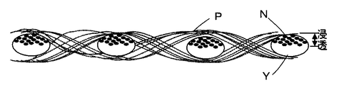
- ink N is ejected from the ink supply device 2.
- the ejected ink N permeates from the front surface to the back surface of the printing material P, and permeates the inside of each yarn that overlaps in the thickness direction.
- the ink N is agglomerated with the coagulant A supplied in advance and is increased to a predetermined viscosity.
- the ink N moves along the yarn by the pitch of the yarn weaving, and at that time, the ink N is increased to a predetermined viscosity.
- the flocculant B is supplied from the second flocculant supply device 3, and the printing material is printed.
- the movement of the ink N in the object P can be completely fixed.
- the printing material P can be uniformly dyed from the front surface to the back surface, and the ink bleed can be accommodated within the woven pitch range as shown in FIG.
- the first flocculant supply device 1 only needs to be able to supply the flocculant A to the inside of the thread of the printing material P.
- the flocculant A is applied to the printing material P by the dipping method. Can be supplied. That is, the printing material P is dipped in the bat 11 containing the flocculant A, and the pickup roller 12 disposed immediately after that immerses the flocculant A to about 10 to 60% (with respect to the weight of the printing material P).
- the flocculant A can be supplied to the inside of the yarn of the printing material P.
- rubber it is preferable to use rubber as the material of the squeeze roller.
- a roll coater, an air spray, an ink jet method, or the like may be used.
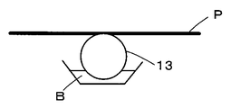
- the second flocculant supply device 3 can supply the flocculant B by a roll coater 13 disposed on the back side of the printing material P, for example, as shown in FIG. In this way, by supplying the flocculant B from the back side of the printing material P, the roll coater 13 does not directly contact the printing surface of the printing material P, and printing disturbance due to the supply of the flocculant B is prevented. Can be suppressed.
- the second flocculant supply device 3 preferably supplies the flocculant B in a small amount as much as possible so as not to affect the movement of the ink that has permeated the printing material P. It is preferable to supply with a smaller size. For example, fine particles of about several ⁇ m to 20 ⁇ m can be supplied by the air spray method, and the supply amount can be adjusted by intermittently spraying the air spray.
- organic cationic polymer as an aggregating agent, a compound having an amino group (—NH 2 ) such as ammonia or alkylamine, and a guanidino group or biguanide group such as arginine, guanidine, or biguanide derivative having more nitrogen.
- a compound having an amino group (—NH 2 ) such as ammonia or alkylamine, and a guanidino group or biguanide group such as arginine, guanidine, or biguanide derivative having more nitrogen.
- a compound having an amino group (—NH 2 ) such as ammonia or alkylamine
- a guanidino group or biguanide group such as arginine, guanidine, or biguanide derivative having more nitrogen.
- synthetic polymers such as polyethyleneimine, polyvinylamine and polyallylamine, and aqueous polymers containing polyamino acids such as polyornithine and polylysine can be used.
- N, N-dimethylaminoethyl acrylate copolymer obtained by copolymerizing acrylamide and N, N-dimethylaminoethyl methacrylate or N, N-dimethylaminoethyl acrylate monomer, polyvinylamidine polymer, amphoteric polymer, etc. Available.
- the aggregation reaction is performed using the anionically charged ink and the cationically charged flocculants A and B.
- the cationically charged ink and the anionic charge are used.
- Aggregation reaction can also be carried out using the resulting flocculants A and B.
- an anionic flocculant for example, a water-soluble or water-dispersible polymer having a carboxylic acid, sulfonic acid or phosphoric acid structure as a hydrophilic group can be used.
- animal and vegetable oils and fats, soda salts such as alkylbenzene sulfonic acids and alkylnaphthalene sulfonic acids, potassium salts and the like can be used.
- the cationic ink includes a cationic colorant such as an alkaline dye and a cationic charge control agent.
- a cationic charge control agent one that becomes a cation when dissociated in water is used, for example, one having tetraalkylammonium as a hydrophilic group.
- alkyltrimethylammonium salt, dialkyldimethylammonium salt, alkylbenzyldimethylammonium salt, or the like can be used.
- the flocculant A supplied from the first flocculant supply device 1 is used when the ink that has been ejected from the ink supply device 2 onto the printing material P penetrates about the thickness of the thread.
- the present invention is not limited to this.
- the coagulation reaction between the coagulant A and the coagulant contained in the ink is performed. You can also control the depth that occurs.
- ink is ejected from the ink supply device 2.
- the ink that has landed on the printing material P penetrates in the direction along the fiber and in the thickness direction of the thread.
- the supply amount of the flocculant A can be adjusted so that the ink N rises to a predetermined viscosity. As a result, the moving speed of the ink N in the direction along the printing material P is reduced, and the ink N is retained near the printing side surface of the printing material P until the flocculant B is supplied.
- the printed ink is transferred to the print-side surface of the printing material P.
- Many can be distributed in the vicinity.
- the color material located near the printing side surface of the printing material P has a large contribution to the optical density at the time of dyeing, and less ink is obtained by distributing a large amount of ink near the printing side surface of the printing material P as described above. Dyeing with sufficient optical density can be realized in an amount.
- the distribution of the color material is controlled to about half the thickness of the printing material P, and ink of a different color is printed from the back surface, thereby creating the printing material P printed in different colors on the front surface and the back surface. You can also
- the flocculant A supplied to the printing material P has a difference in its distribution due to a difference in capillary force caused by a difference in fiber density of the printing material P. If a high-concentration flocculant A that aggregates instantaneously immediately after ink is printed is used, it becomes difficult to uniformly dye the printing material P. For this reason, it is required that the ink permeates moderately in the depth direction of the printing material P. That is, the supply amount of the flocculant A is adjusted so that all the inks penetrating the printing material P will aggregate after reaching a substantially uniform depth position. Specifically, it is possible to use a solution prepared by increasing the concentration of the flocculant A used in Embodiment 1 to about 2 to 3 times.
- the printing side of the printing material P out of the flocculant A supplied from the first flocculant supply device 1 to the printing material P. Only what is located near the surface contributes to the aggregation reaction with the aggregating agent in the ink, and the total amount of the printing ink may not be increased to a predetermined viscosity. In particular, this phenomenon is likely to occur in an area where a large amount of ink is printed in order to perform dark color dyeing. Specifically, a problem when printing the amount of printing of about 20% of the printing object weight (for the printing of 1 m 2 per 100 g, 1 m 2 per 20g or higher).
- the flocculant B is supplied from the second flocculant supply device 3 to the printing material P.
- the concentration of the flocculant B is adjusted so as to exceed the isoelectric point of the flocculant by reacting with the flocculant contained in the ink together with the flocculant A previously supplied.
- the movement of the ink kept at a predetermined viscosity in the vicinity of the print side surface of P is completely stopped by the aggregation reaction with the flocculant B.
- the ink that has uniformly penetrated the vicinity of the printing side surface of the printing material P can be fixed without diffusing in the direction along the printing material P.
- the aggregating agent B is preferably supplied after the ink is printed on the printing material P and before the non-aggregated ink moves due to capillary force to cause density unevenness, and is supplied from the same direction as the ink printing direction. Is desirable. For this reason, as the second flocculant supply device 3, for example, a supply device such as an ink jet method, an air spray method, or a roll coater is preferably used.
- the printing material P is sequentially moved to the drying device 5, the color processing device 6 and the washing / drying device 7 in a state where the ink is fixed in the vicinity of the printing side surface, and the coloring material is fixed to the printing material P.
- the dyeing of the printing material P is completed.
- ink is printed by the ink supply device 2 immediately after the flocculant A is supplied from the first flocculant supply device 1 to the printing material P.
- the drying device 14 is arranged between the first flocculant supply device 1 and the ink supply device 2, and the printing target to which the flocculant A is supplied from the first flocculant supply device 1.
- the product P can be once dried by the drying device 14.
- the dried printing material P is supplied to the ink supply device 2, and the ink ejected from the ink supply device 2 and the aggregating agent A in the printing material P undergo an agglomeration reaction to increase the viscosity to a predetermined viscosity.
- the remaining ink is kept within a certain range of the printing material P.
- the flocculant B is supplied from the second flocculant supply device 3 to the printing material P, and the ink is completely fixed to the printing material P.
- the color material is fixed on the printing material P.
- the printing apparatus used in the printing method according to the third embodiment automates the respective supplies by calculating the supply amounts of ink, flocculant A, and flocculant B based on input data. At the same time, by feeding back the result printed on the substrate P, the respective supply amounts can be corrected in sequence. Further, the permeation position of the ink into the printing material P can be controlled by switching the supply amount or type of the flocculant A. Furthermore, by performing printing and color processing, etc., and measuring the optical characteristics of the printed material P that has been dyed on both front and back sides, the ink penetration position into the printed material P is measured and the result is fed back. Is also possible.
- the printing apparatus used in the present embodiment includes a supply amount calculation unit 21, a control unit 22, and a drive unit 23 that are sequentially connected.
- This drive unit 23 is the first of the printing apparatus used in the first embodiment.
- the flocculant supply device 1, the ink supply device 2, and the second flocculant supply device 3 are connected.
- the ink supply device 2a can also be arranged on the back side of the substrate P.
- the printing apparatus arranges measuring devices 24 and 24a on the front surface side and the back surface side, respectively, on the downstream side of the fixing device 4 with respect to the moving direction of the printing material P, and inputs print result measurement values to the measuring devices 24 and 24a.
- the printing result measurement value input unit 25 is connected to the supply amount calculation unit 21 while the unit 25 is connected.
- information relating to the supply amounts of ink, flocculant A, and flocculant B is input to the supply amount calculator 21 as input data by an operator.
- information relating to the amount of ink supplied information on a print image (color for each pixel, etc.), information on a printing material P (material, thickness, thread thickness, etc.), and the like are input.
- information on the flocculants A and B information on the printing material P, ink information (type, concentration, isoelectric point of the flocculant, etc.) and the like are input.
- the supply amount calculation unit 21 calculates the supply amounts of ink, flocculant A, and flocculant B based on the input information, and outputs the calculated amounts to the control unit 22.
- the control unit 22 outputs the supply amounts of the coagulant A, the ink, and the coagulant B to the drive unit 23 at appropriate times
- the drive unit 23 outputs a drive signal corresponding to each supply amount to the first coagulant.
- the output is supplied to the supply device 1, the ink supply device 2, the ink supply device 2 a, and the second flocculant supply device 3, and the flocculant A, ink, and flocculant B are sequentially supplied to the printing material P.
- the ink supply device 2a can be used when, for example, droplets of ink having a different color from the ink supply device 2 are ejected, and can dye the printed material P in different colors on the front surface and the back surface. Subsequently, the ink fixed to the printing material P is fixed to the printing material P by the fixing device 4, whereby the printing on the printing material P is completed.
- the printed image printed on the printing material P is measured for optical characteristics by measuring devices 24 and 24a including optical sensors, and the measured values are input to the printing result measurement value input unit 25, whereby the printing material P is printed. The result printed on is fed back.
- the supply amount calculation unit 21 corrects and corrects the supply amounts of the ink, the coagulant A, and the coagulant B so as to realize the target color development based on the measurement value input from the print result measurement value input unit 25.
- the driving unit 23 drives the first coagulant supply device 1, the ink supply device 2, and the second coagulant supply device 3 in accordance with the respective supply amounts, and printing on the printing material P is performed.
- an appropriate amount can be automatically supplied to the printing material P by only inputting information on the supply amount of the ink, the flocculant A, and the flocculant B, respectively. Further, since the result of printing on the printing material P is fed back and printed on the printing material P again based on the corrected amount of ink, the coagulant A and the coagulant B, the initial supply amount is poor, or Even when the physical properties of the ink and the printing material P change, the variation in color can be effectively suppressed.
Landscapes
- Engineering & Computer Science (AREA)
- Textile Engineering (AREA)
- Ink Jet (AREA)
- Ink Jet Recording Methods And Recording Media Thereof (AREA)
- Coloring (AREA)
Abstract
La présente invention porte sur un procédé d'impression, dans lequel procédé un premier agent de floculation pour provoquer l'élévation à une viscosité prédéterminée d'une encre éjectée en gouttelettes dans un procédé à jet d'encre est délivré à l'avance à un article à imprimer, de l'encre est éjectée en gouttelettes sur l'article à l'aide d'un procédé à jet d'encre, et un second agent de floculation est délivré à l'article de façon à fixer l'encre élevée à une viscosité prédéterminée par le premier agent de floculation.
Priority Applications (1)
| Application Number | Priority Date | Filing Date | Title |
|---|---|---|---|
| JP2013536013A JP5840217B2 (ja) | 2011-09-26 | 2012-07-20 | 印字方法および印字装置 |
Applications Claiming Priority (4)
| Application Number | Priority Date | Filing Date | Title |
|---|---|---|---|
| JP2011209053 | 2011-09-26 | ||
| JP2011-209053 | 2011-09-26 | ||
| JP2012-014803 | 2012-01-27 | ||
| JP2012014803 | 2012-01-27 |
Publications (1)
| Publication Number | Publication Date |
|---|---|
| WO2013046884A1 true WO2013046884A1 (fr) | 2013-04-04 |
Family
ID=47994939
Family Applications (1)
| Application Number | Title | Priority Date | Filing Date |
|---|---|---|---|
| PCT/JP2012/068443 Ceased WO2013046884A1 (fr) | 2011-09-26 | 2012-07-20 | Procédé d'impression et dispositif d'impression |
Country Status (2)
| Country | Link |
|---|---|
| JP (1) | JP5840217B2 (fr) |
| WO (1) | WO2013046884A1 (fr) |
Cited By (6)
| Publication number | Priority date | Publication date | Assignee | Title |
|---|---|---|---|---|
| EP3532548A4 (fr) * | 2016-10-31 | 2020-07-22 | Kornit Digital Ltd. | Impression par jet d'encre par sublimation de colorant pour textile |
| US11021627B2 (en) | 2009-08-10 | 2021-06-01 | Kornit Digital Ltd. | Inkjet compositions and processes for stretchable substrates |
| US11447648B2 (en) | 2004-05-30 | 2022-09-20 | Kornit Digital Ltd. | Process and system for printing images on absorptive surfaces |
| US20220389256A1 (en) * | 2021-06-02 | 2022-12-08 | Taiwan Textile Research Institute | Digital printed fabric, manufacturing method for digital printed fabric, and digital printing ink |
| US11629265B2 (en) | 2017-10-22 | 2023-04-18 | Kornit Digital Ltd. | Low-friction images by inkjet printing |
| US12617964B2 (en) * | 2021-06-02 | 2026-05-05 | Taiwan Textile Research Institute | Digital printed fabric, manufacturing method for digital printed fabric, and digital printing ink |
Citations (4)
| Publication number | Priority date | Publication date | Assignee | Title |
|---|---|---|---|---|
| JPH08157731A (ja) * | 1994-12-08 | 1996-06-18 | Canon Inc | 液体組成物、インクセット及びこれを用いた画像形成方法と装置 |
| JPH08197840A (ja) * | 1995-01-31 | 1996-08-06 | Canon Inc | 液体組成物、インクセット及びこれを用いた画像形成方法と装置 |
| JP2008231617A (ja) * | 2007-03-20 | 2008-10-02 | Canon Inc | インクジェット捺染方法及び捺染物 |
| JP2011031479A (ja) * | 2009-07-31 | 2011-02-17 | Seiko Epson Corp | インクジェット記録方法 |
Family Cites Families (1)
| Publication number | Priority date | Publication date | Assignee | Title |
|---|---|---|---|---|
| JP2000218772A (ja) * | 1999-01-28 | 2000-08-08 | Canon Inc | インクジェット記録装置およびインクジェット記録方法 |
-
2012
- 2012-07-20 WO PCT/JP2012/068443 patent/WO2013046884A1/fr not_active Ceased
- 2012-07-20 JP JP2013536013A patent/JP5840217B2/ja not_active Expired - Fee Related
Patent Citations (4)
| Publication number | Priority date | Publication date | Assignee | Title |
|---|---|---|---|---|
| JPH08157731A (ja) * | 1994-12-08 | 1996-06-18 | Canon Inc | 液体組成物、インクセット及びこれを用いた画像形成方法と装置 |
| JPH08197840A (ja) * | 1995-01-31 | 1996-08-06 | Canon Inc | 液体組成物、インクセット及びこれを用いた画像形成方法と装置 |
| JP2008231617A (ja) * | 2007-03-20 | 2008-10-02 | Canon Inc | インクジェット捺染方法及び捺染物 |
| JP2011031479A (ja) * | 2009-07-31 | 2011-02-17 | Seiko Epson Corp | インクジェット記録方法 |
Cited By (8)
| Publication number | Priority date | Publication date | Assignee | Title |
|---|---|---|---|---|
| US11447648B2 (en) | 2004-05-30 | 2022-09-20 | Kornit Digital Ltd. | Process and system for printing images on absorptive surfaces |
| US11021627B2 (en) | 2009-08-10 | 2021-06-01 | Kornit Digital Ltd. | Inkjet compositions and processes for stretchable substrates |
| US11898048B2 (en) | 2009-08-10 | 2024-02-13 | Kornit Digital Ltd. | Inkjet compositions and processes for stretchable substrates |
| EP3532548A4 (fr) * | 2016-10-31 | 2020-07-22 | Kornit Digital Ltd. | Impression par jet d'encre par sublimation de colorant pour textile |
| US11098214B2 (en) | 2016-10-31 | 2021-08-24 | Kornit Digital Ltd. | Dye-sublimation inkjet printing for textile |
| US11629265B2 (en) | 2017-10-22 | 2023-04-18 | Kornit Digital Ltd. | Low-friction images by inkjet printing |
| US20220389256A1 (en) * | 2021-06-02 | 2022-12-08 | Taiwan Textile Research Institute | Digital printed fabric, manufacturing method for digital printed fabric, and digital printing ink |
| US12617964B2 (en) * | 2021-06-02 | 2026-05-05 | Taiwan Textile Research Institute | Digital printed fabric, manufacturing method for digital printed fabric, and digital printing ink |
Also Published As
| Publication number | Publication date |
|---|---|
| JP5840217B2 (ja) | 2016-01-06 |
| JPWO2013046884A1 (ja) | 2015-03-26 |
Similar Documents
| Publication | Publication Date | Title |
|---|---|---|
| JP5893850B2 (ja) | 印字方法および印字装置 | |
| US20240182740A1 (en) | Inkjet compositions and processes for stretchable substrates | |
| EP1670983B1 (fr) | Procede et dispositif pour le revetement numerique d'un textile et textile comportant un revetement numerique | |
| US11566143B2 (en) | Image forming method and ink set | |
| JP5840217B2 (ja) | 印字方法および印字装置 | |
| US9387700B2 (en) | Digital imaging process for flooring material | |
| EP0682147B1 (fr) | Tissu pour impression pour jet d'encre, procédé d'impression et imprimé obtenu par ce procédé | |
| WO2021061147A1 (fr) | Impression sur textile | |
| JP5203924B2 (ja) | 布製品の連続インクジェット仕上げ処理のための組成物 | |
| EP3778798B1 (fr) | Composition d'encre pour jet d'encre, procédé d'entretien, procédé d'enregistrement d'image et matériau à image imprimée | |
| JP2013221221A (ja) | 印字装置および印字方法 | |
| JP2008534792A (ja) | 布地の基材に物質を付着させる方法 | |
| JP5914157B2 (ja) | 印字方法および印字装置 | |
| JP2018035481A (ja) | 捺染方法、染色装置、捺染用インク及び処理用インク | |
| JP2013216991A (ja) | 印字方法および印字装置 | |
| JP5840564B2 (ja) | 印字方法および印字装置 | |
| JP2008537573A (ja) | 布製品のドロップ・オン・デマンド仕上げ処理のための組成物 | |
| JP3410026B2 (ja) | インクジェット捺染用皮革及びその製造方法 | |
| WO2012005103A1 (fr) | Procédé d'impression, dispositif d'impression et nappe à force capillaire | |
| CN105522836B (zh) | 数码喷墨印花方法 | |
| JP2021088096A (ja) | 画像形成方法および画像形成装置 | |
| WO2024186689A1 (fr) | Procédé de prétraitement d'un textile avec un revêtement d'apprêt pulvérisable par jet avant l'impression | |
| Ushiku et al. | Fabric coating and printing conjoined in a single inkjet textile printing process |
Legal Events
| Date | Code | Title | Description |
|---|---|---|---|
| 121 | Ep: the epo has been informed by wipo that ep was designated in this application |
Ref document number: 12836888 Country of ref document: EP Kind code of ref document: A1 |
|
| ENP | Entry into the national phase |
Ref document number: 2013536013 Country of ref document: JP Kind code of ref document: A |
|
| NENP | Non-entry into the national phase |
Ref country code: DE |
|
| 122 | Ep: pct application non-entry in european phase |
Ref document number: 12836888 Country of ref document: EP Kind code of ref document: A1 |