WO2013051105A1 - 受電装置、送電装置および電力伝送システム - Google Patents
受電装置、送電装置および電力伝送システム Download PDFInfo
- Publication number
- WO2013051105A1 WO2013051105A1 PCT/JP2011/072839 JP2011072839W WO2013051105A1 WO 2013051105 A1 WO2013051105 A1 WO 2013051105A1 JP 2011072839 W JP2011072839 W JP 2011072839W WO 2013051105 A1 WO2013051105 A1 WO 2013051105A1
- Authority
- WO
- WIPO (PCT)
- Prior art keywords
- coil
- power
- power transmission
- unit
- power receiving
- Prior art date
- Legal status (The legal status is an assumption and is not a legal conclusion. Google has not performed a legal analysis and makes no representation as to the accuracy of the status listed.)
- Ceased
Links
Images






Classifications
-
- B—PERFORMING OPERATIONS; TRANSPORTING
- B60—VEHICLES IN GENERAL
- B60L—PROPULSION OF ELECTRICALLY-PROPELLED VEHICLES; SUPPLYING ELECTRIC POWER FOR AUXILIARY EQUIPMENT OF ELECTRICALLY-PROPELLED VEHICLES; ELECTRODYNAMIC BRAKE SYSTEMS FOR VEHICLES IN GENERAL; MAGNETIC SUSPENSION OR LEVITATION FOR VEHICLES; MONITORING OPERATING VARIABLES OF ELECTRICALLY-PROPELLED VEHICLES; ELECTRIC SAFETY DEVICES FOR ELECTRICALLY-PROPELLED VEHICLES
- B60L53/00—Methods of charging batteries, specially adapted for electric vehicles; Charging stations or on-board charging equipment therefor; Exchange of energy storage elements in electric vehicles
- B60L53/10—Methods of charging batteries, specially adapted for electric vehicles; Charging stations or on-board charging equipment therefor; Exchange of energy storage elements in electric vehicles characterised by the energy transfer between the charging station and the vehicle
- B60L53/12—Inductive energy transfer
- B60L53/126—Methods for pairing a vehicle and a charging station, e.g. establishing a one-to-one relation between a wireless power transmitter and a wireless power receiver
-
- B—PERFORMING OPERATIONS; TRANSPORTING
- B60—VEHICLES IN GENERAL
- B60L—PROPULSION OF ELECTRICALLY-PROPELLED VEHICLES; SUPPLYING ELECTRIC POWER FOR AUXILIARY EQUIPMENT OF ELECTRICALLY-PROPELLED VEHICLES; ELECTRODYNAMIC BRAKE SYSTEMS FOR VEHICLES IN GENERAL; MAGNETIC SUSPENSION OR LEVITATION FOR VEHICLES; MONITORING OPERATING VARIABLES OF ELECTRICALLY-PROPELLED VEHICLES; ELECTRIC SAFETY DEVICES FOR ELECTRICALLY-PROPELLED VEHICLES
- B60L53/00—Methods of charging batteries, specially adapted for electric vehicles; Charging stations or on-board charging equipment therefor; Exchange of energy storage elements in electric vehicles
- B60L53/60—Monitoring or controlling charging stations
- B60L53/62—Monitoring or controlling charging stations in response to charging parameters, e.g. current, voltage or electrical charge
-
- H—ELECTRICITY
- H01—ELECTRIC ELEMENTS
- H01F—MAGNETS; INDUCTANCES; TRANSFORMERS; SELECTION OF MATERIALS FOR THEIR MAGNETIC PROPERTIES
- H01F27/00—Details of transformers or inductances, in general
- H01F27/006—Details of transformers or inductances, in general with special arrangement or spacing of turns of the winding(s), e.g. to produce desired self-resonance
-
- H—ELECTRICITY
- H01—ELECTRIC ELEMENTS
- H01F—MAGNETS; INDUCTANCES; TRANSFORMERS; SELECTION OF MATERIALS FOR THEIR MAGNETIC PROPERTIES
- H01F38/00—Adaptations of transformers or inductances for specific applications or functions
- H01F38/14—Inductive couplings
-
- H—ELECTRICITY
- H02—GENERATION; CONVERSION OR DISTRIBUTION OF ELECTRIC POWER
- H02J—ELECTRIC POWER NETWORKS; CIRCUIT ARRANGEMENTS OR SYSTEMS FOR SUPPLYING OR DISTRIBUTING ELECTRIC POWER; SYSTEMS FOR STORING ELECTRIC ENERGY
- H02J50/00—Circuit arrangements or systems for wireless supply or distribution of electric power
- H02J50/005—Mechanical details of housing or structure aiming to accommodate the power transfer means, e.g. mechanical integration of coils, antennas or transducers into emitting or receiving devices
-
- H—ELECTRICITY
- H02—GENERATION; CONVERSION OR DISTRIBUTION OF ELECTRIC POWER
- H02J—ELECTRIC POWER NETWORKS; CIRCUIT ARRANGEMENTS OR SYSTEMS FOR SUPPLYING OR DISTRIBUTING ELECTRIC POWER; SYSTEMS FOR STORING ELECTRIC ENERGY
- H02J50/00—Circuit arrangements or systems for wireless supply or distribution of electric power
- H02J50/10—Circuit arrangements or systems for wireless supply or distribution of electric power using inductive coupling
- H02J50/12—Circuit arrangements or systems for wireless supply or distribution of electric power using inductive coupling of the resonant type
-
- H—ELECTRICITY
- H02—GENERATION; CONVERSION OR DISTRIBUTION OF ELECTRIC POWER
- H02J—ELECTRIC POWER NETWORKS; CIRCUIT ARRANGEMENTS OR SYSTEMS FOR SUPPLYING OR DISTRIBUTING ELECTRIC POWER; SYSTEMS FOR STORING ELECTRIC ENERGY
- H02J50/00—Circuit arrangements or systems for wireless supply or distribution of electric power
- H02J50/70—Circuit arrangements or systems for wireless supply or distribution of electric power involving the reduction of electric, magnetic or electromagnetic leakage fields
-
- H—ELECTRICITY
- H02—GENERATION; CONVERSION OR DISTRIBUTION OF ELECTRIC POWER
- H02J—ELECTRIC POWER NETWORKS; CIRCUIT ARRANGEMENTS OR SYSTEMS FOR SUPPLYING OR DISTRIBUTING ELECTRIC POWER; SYSTEMS FOR STORING ELECTRIC ENERGY
- H02J2105/00—Networks for supplying or distributing electric power characterised by their spatial reach or by the load
- H02J2105/30—Networks for supplying or distributing electric power characterised by their spatial reach or by the load the load networks being external to vehicles, i.e. exchanging power with vehicles
- H02J2105/33—Networks for supplying or distributing electric power characterised by their spatial reach or by the load the load networks being external to vehicles, i.e. exchanging power with vehicles exchanging power with road vehicles
- H02J2105/37—Networks for supplying or distributing electric power characterised by their spatial reach or by the load the load networks being external to vehicles, i.e. exchanging power with vehicles exchanging power with road vehicles exchanging power with electric vehicles [EV] or with hybrid electric vehicles [HEV]
-
- Y—GENERAL TAGGING OF NEW TECHNOLOGICAL DEVELOPMENTS; GENERAL TAGGING OF CROSS-SECTIONAL TECHNOLOGIES SPANNING OVER SEVERAL SECTIONS OF THE IPC; TECHNICAL SUBJECTS COVERED BY FORMER USPC CROSS-REFERENCE ART COLLECTIONS [XRACs] AND DIGESTS
- Y02—TECHNOLOGIES OR APPLICATIONS FOR MITIGATION OR ADAPTATION AGAINST CLIMATE CHANGE
- Y02T—CLIMATE CHANGE MITIGATION TECHNOLOGIES RELATED TO TRANSPORTATION
- Y02T10/00—Road transport of goods or passengers
- Y02T10/60—Other road transportation technologies with climate change mitigation effect
- Y02T10/70—Energy storage systems for electromobility, e.g. batteries
-
- Y—GENERAL TAGGING OF NEW TECHNOLOGICAL DEVELOPMENTS; GENERAL TAGGING OF CROSS-SECTIONAL TECHNOLOGIES SPANNING OVER SEVERAL SECTIONS OF THE IPC; TECHNICAL SUBJECTS COVERED BY FORMER USPC CROSS-REFERENCE ART COLLECTIONS [XRACs] AND DIGESTS
- Y02—TECHNOLOGIES OR APPLICATIONS FOR MITIGATION OR ADAPTATION AGAINST CLIMATE CHANGE
- Y02T—CLIMATE CHANGE MITIGATION TECHNOLOGIES RELATED TO TRANSPORTATION
- Y02T10/00—Road transport of goods or passengers
- Y02T10/60—Other road transportation technologies with climate change mitigation effect
- Y02T10/7072—Electromobility specific charging systems or methods for batteries, ultracapacitors, supercapacitors or double-layer capacitors
-
- Y—GENERAL TAGGING OF NEW TECHNOLOGICAL DEVELOPMENTS; GENERAL TAGGING OF CROSS-SECTIONAL TECHNOLOGIES SPANNING OVER SEVERAL SECTIONS OF THE IPC; TECHNICAL SUBJECTS COVERED BY FORMER USPC CROSS-REFERENCE ART COLLECTIONS [XRACs] AND DIGESTS
- Y02—TECHNOLOGIES OR APPLICATIONS FOR MITIGATION OR ADAPTATION AGAINST CLIMATE CHANGE
- Y02T—CLIMATE CHANGE MITIGATION TECHNOLOGIES RELATED TO TRANSPORTATION
- Y02T90/00—Enabling technologies or technologies with a potential or indirect contribution to GHG emissions mitigation
- Y02T90/10—Technologies relating to charging of electric vehicles
- Y02T90/12—Electric charging stations
-
- Y—GENERAL TAGGING OF NEW TECHNOLOGICAL DEVELOPMENTS; GENERAL TAGGING OF CROSS-SECTIONAL TECHNOLOGIES SPANNING OVER SEVERAL SECTIONS OF THE IPC; TECHNICAL SUBJECTS COVERED BY FORMER USPC CROSS-REFERENCE ART COLLECTIONS [XRACs] AND DIGESTS
- Y02—TECHNOLOGIES OR APPLICATIONS FOR MITIGATION OR ADAPTATION AGAINST CLIMATE CHANGE
- Y02T—CLIMATE CHANGE MITIGATION TECHNOLOGIES RELATED TO TRANSPORTATION
- Y02T90/00—Enabling technologies or technologies with a potential or indirect contribution to GHG emissions mitigation
- Y02T90/10—Technologies relating to charging of electric vehicles
- Y02T90/14—Plug-in electric vehicles
-
- Y—GENERAL TAGGING OF NEW TECHNOLOGICAL DEVELOPMENTS; GENERAL TAGGING OF CROSS-SECTIONAL TECHNOLOGIES SPANNING OVER SEVERAL SECTIONS OF THE IPC; TECHNICAL SUBJECTS COVERED BY FORMER USPC CROSS-REFERENCE ART COLLECTIONS [XRACs] AND DIGESTS
- Y02—TECHNOLOGIES OR APPLICATIONS FOR MITIGATION OR ADAPTATION AGAINST CLIMATE CHANGE
- Y02T—CLIMATE CHANGE MITIGATION TECHNOLOGIES RELATED TO TRANSPORTATION
- Y02T90/00—Enabling technologies or technologies with a potential or indirect contribution to GHG emissions mitigation
- Y02T90/10—Technologies relating to charging of electric vehicles
- Y02T90/16—Information or communication technologies improving the operation of electric vehicles
Definitions
- the present invention relates to a power receiving device, a power transmission device, and a power transmission system.
- a vehicle described in Japanese Patent Application Laid-Open No. 2010-87353 includes a non-contact power transmission device.
- the non-contact power transmission device includes a resonance coil provided on the facility side and a resonance coil that magnetically resonates, and the resonance And a bobbin for supporting the coil.
- the bobbin is made of a resin material and has a bottomed cylindrical shape.
- the resonance coil is provided on the inner peripheral surface of the bobbin.
- the bobbin if a current flows in the resonance coil during power transmission, the bobbin generates heat at the portion where the bobbin and the resonance coil are in contact with each other, resulting in dielectric loss. For this reason, the power transmission efficiency when the power is transmitted from the equipment side to the vehicle is significantly reduced.
- the cross-sectional shape of the resonance coil is a circular shape
- the shape of the groove formed on the inner peripheral surface of the bobbin is also formed along the shape of the resonance coil
- the cross-sectional shape of the groove is formed in a semicircular shape.
- the resonance coil becomes high temperature.
- the bobbin in contact with the resonance coil also becomes high temperature.
- the bobbin expands, and the groove part that receives the resonance coil becomes small, and the resonance coil fitted in the groove part may fall off from the bobbin.
- the present invention has been made in view of the above problems, and an object of the present invention is to provide a power receiving device, a power transmitting device, and a power transmission system in which the loss of the coil is suppressed while the dielectric loss is reduced. That is.
- the power receiving device includes a power receiving unit that receives power in a non-contact manner from power transmitting units arranged at intervals, and a first holding unit that holds the power receiving unit.
- the power receiving unit includes a power receiving coil.
- the power receiving coil is formed by winding a first coil wire having a width larger than the thickness.
- the first holding unit includes a plurality of first coil holding members extending in a direction in which the power receiving coil extends and having a first groove portion that receives the power receiving coil. At least a part of the first groove is formed such that the depth of the first groove extending in the width direction of the first coil wire is larger than the width of the first groove extending in the thickness direction of the first coil wire.
- the width of the first coil wire is larger than the depth of the first groove portion.
- the first coil holding member is adjacent to the first groove portion in the width direction of the first groove portion, and is opposite to the first support portion with respect to the first groove portion and a first support portion that supports the power receiving coil. And a second support part that supports the power receiving coil. At least one of the first support portion and the second support portion is formed such that the length in the direction in which the power receiving coil extends becomes longer toward the bottom portion of the first groove portion.
- the first coil holding member is formed in a columnar shape, and a plurality of first groove portions are formed at intervals in the height direction of the first coil holding member.
- the first coil holding member is disposed inside the power receiving coil, and is disposed at an interval along the power receiving coil.
- both ends of the power receiving coil are drawn inside the power receiving coil.
- Capacitors connected to both ends of the power receiving coil are further provided.
- the apparatus further includes a first housing case that houses the power reception unit and the first holding unit.
- the first housing case includes a top plate portion, a bottom surface portion facing the top plate portion, and a peripheral wall portion connecting the top plate portion and the bottom surface portion.
- the first coil holding member is connected to the top plate portion and the bottom surface portion.
- the difference between the natural frequency of the power transmission unit and the natural frequency of the power reception unit is 10% or less of the natural frequency of the power reception unit.
- the coupling coefficient between the power reception unit and the power transmission unit is 0.1 or less.
- the power reception unit includes a magnetic field formed between the power reception unit and the power transmission unit and oscillating at a specific frequency, and an electric field formed between the power reception unit and the power transmission unit and oscillating at a specific frequency. Power is received from the power transmission unit through at least one of them.
- the power transmission device includes a power transmission unit that transmits power in a non-contact manner to power reception units arranged at intervals, and a second holding unit that holds the power transmission unit.
- the power transmission unit includes a power transmission coil.
- the power transmission coil is formed by winding a second coil wire having a width larger than the thickness.
- the second holding unit includes a plurality of second coil holding members extending in a direction in which the power transmission coil extends and having a second groove portion that receives the power transmission coil. At least a part of the second groove is formed such that the depth of the second groove extending in the width direction of the second coil wire is larger than the width of the second groove extending in the thickness direction of the second coil wire.
- the width of the second coil wire is larger than the depth of the second groove portion.
- the second coil holding member is adjacent to the second groove portion in the width direction of the second groove portion and supports the power transmission coil, and is opposite to the third support portion with respect to the second groove portion.
- a fourth support part that is located on the side and supports the power transmission coil.
- At least one of the third support part and the fourth support part is formed so that the length in the direction in which the power transmission coil extends becomes longer toward the bottom of the second groove part.
- the second coil holding member is formed in a columnar shape, and a plurality of second groove portions are formed at intervals in the height direction of the second coil holding member.
- the two-coil holding member is disposed inside the power transmission coil.
- both ends of the power transmission coil are drawn inside the power transmission coil.
- Capacitors connected to both ends of the power transmission coil are further provided.
- the apparatus further includes a second housing case that houses the power transmission unit and the second holding unit.
- the second housing case includes a top plate portion, a bottom surface portion facing the top plate portion, and a peripheral wall portion connecting the top plate portion and the bottom surface portion.
- the second coil holding member is connected to the top plate portion and the bottom surface portion.
- the difference between the natural frequency of the power transmission unit and the natural frequency of the power reception unit is 10% or less of the natural frequency of the power reception unit.
- the coupling coefficient between the power reception unit and the power transmission unit is 0.1 or less.
- the power transmission unit includes a magnetic field that is formed between the power reception unit and the power transmission unit and vibrates at a specific frequency, and an electric field that is formed between the power reception unit and the power transmission unit and vibrates at a specific frequency. Electric power is transmitted to the power receiving unit through at least one of them.
- the power transmission system includes a power transmission device including a power transmission unit, and a power reception device that receives power from the power transmission device in a contactless manner.
- the power reception device includes a power reception unit that receives power from the power transmission unit in a contactless manner, and a first holding unit that holds the power reception unit.
- the power transmission device includes a second holding unit that holds the power transmission unit.
- the power receiving unit includes a power receiving coil. The power receiving coil is formed by winding a first coil wire having a width larger than the thickness.
- the first holding unit includes a plurality of first coil holding members extending in a direction in which the power receiving coil extends and having a first groove portion for receiving the power receiving coil. In at least a part of the first groove portion, the depth of the first groove portion extending in the width direction of the first coil wire is larger than the width of the first groove portion extending in the thickness direction of the first coil wire.
- the power transmission unit includes a power transmission coil. The power transmission coil is formed by winding a second coil wire having a width larger than the thickness.
- the second holding unit includes a plurality of second coil holding members extending in a direction in which the power transmission coil extends and having a second groove portion that receives the power transmission coil. At least a part of the second groove part has a depth of the second groove part extending in the width direction of the second coil wire larger than the width of the second groove part extending in the thickness direction of the second coil wire.
- the difference between the natural frequency of the power transmission unit and the natural frequency of the power reception unit is 10% or less of the natural frequency of the power reception unit.
- the coupling coefficient between the power reception unit and the power transmission unit is 0.1 or less.
- the power reception unit includes a magnetic field formed between the power reception unit and the power transmission unit and oscillating at a specific frequency, and an electric field formed between the power reception unit and the power transmission unit and oscillating at a specific frequency. Power is received from the power transmission unit through at least one of them.
- the power receiving device According to the power receiving device, the power transmitting device, and the power transmission system according to the present invention, it is possible to reduce the dielectric loss and to suppress the coil from falling off.
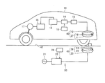
- FIG. 1 It is a schematic diagram which shows typically the power receiving apparatus which concerns on this Embodiment, a power transmission apparatus, and an electric power transmission system.
- a simulation model of a power transmission system is shown. A grab showing the simulation results.
- FIG. 14 is a cross-sectional view taken along line XIV-XIV shown in FIG. 13.
- FIG. 15 is a cross-sectional view taken along line XV-XV shown in FIG.
- It is a perspective view which shows a power transmission apparatus. It is a disassembled perspective view of a power transmission apparatus. It is sectional drawing of a power transmission apparatus. It is a perspective view which shows a power transmission part. It is sectional drawing which shows a coil wire. It is sectional drawing which shows a coil wire.
- FIG. 1 is a perspective view showing a coil holding member 1.
- FIG. It is a side view of the coil holding member shown in FIG.
- FIG. 24 is a cross-sectional view taken along line XXIV-XXIV shown in FIG.
- FIG. 25 is a cross-sectional view taken along line XXV-XXV shown in FIG. 24.
- FIG. 1 is a schematic diagram schematically showing a power reception device, a power transmission device, and a power transmission system according to the present embodiment.
- the power transmission system includes an electric vehicle 10 including a power receiving device and an external power feeding device 20 including a power transmission device 41.
- the power receiving device of the electric vehicle 10 stops at a predetermined position of the parking space 42 where the power transmission device 41 is provided, and mainly receives power from the power transmission device 41.
- the parking space 42 is provided with a stop and a line so that the electric vehicle 10 stops at a predetermined position.
- the external power supply device 20 includes a high frequency power driver 22 connected to the AC power source 21, a control unit 26 that controls driving of the high frequency power driver 22, and a power transmission device 41 connected to the high frequency power driver 22.
- the power transmission device 41 includes a power transmission unit 28 and an electromagnetic induction coil 23.
- the power transmission unit 28 includes a resonance coil 24 and a capacitor 25 connected to the resonance coil 24.
- the electromagnetic induction coil 23 is electrically connected to the high frequency power driver 22.
- the capacitor 25 is provided, but the capacitor 25 is not necessarily an essential configuration.
- the power transmission unit 28 includes an electric circuit formed by the inductance of the resonance coil 24, the stray capacitance of the resonance coil 24, and the capacitance of the capacitor 25.
- the electric vehicle 10 includes a power receiving device 40, a rectifier 13 connected to the power receiving device 40, a DC / DC converter 14 connected to the rectifier 13, a battery 15 connected to the DC / DC converter 14, a power A control unit (PCU (Power Control Unit)) 16, a motor unit 17 connected to the power control unit 16, a vehicle ECU (Electronic Control Unit) that controls driving of the DC / DC converter 14, the power control unit 16, and the like 18.
- Electric vehicle 10 according to the present embodiment is a hybrid vehicle including an engine (not shown), but includes an electric vehicle and a fuel cell vehicle as long as the vehicle is driven by a motor.
- the rectifier 13 is connected to the electromagnetic induction coil 12, converts an alternating current supplied from the electromagnetic induction coil 12 into a direct current, and supplies the direct current to the DC / DC converter 14.
- the DC / DC converter 14 adjusts the voltage of the direct current supplied from the rectifier 13 and supplies it to the battery 15.
- the DC / DC converter 14 is not an essential component and may be omitted. In this case, the DC / DC converter 14 can be substituted by providing a matching unit for matching impedance with the external power supply device 20 between the power transmission device 41 and the high-frequency power driver 22.
- the power control unit 16 includes a converter connected to the battery 15 and an inverter connected to the converter, and the converter adjusts (boosts) the direct current supplied from the battery 15 and supplies the DC current to the inverter.
- the inverter converts the direct current supplied from the converter into an alternating current and supplies it to the motor unit 17.
- the motor unit 17 employs, for example, a three-phase AC motor and is driven by an AC current supplied from an inverter of the power control unit 16.
- the electric vehicle 10 When the electric vehicle 10 is a hybrid vehicle, the electric vehicle 10 further includes an engine and a power split mechanism, and the motor unit 17 mainly functions as a motor generator that functions mainly as a generator and an electric motor. Including a motor generator.
- the power receiving device 40 includes a power receiving unit 27 and an electromagnetic induction coil 12.
- the power receiving unit 27 includes the resonance coil 11 and the capacitor 19.
- the resonance coil 11 has a stray capacitance. For this reason, the power reception unit 27 has an electric circuit formed by the inductance of the resonance coil 11 and the capacitances of the resonance coil 11 and the capacitor 19.
- the capacitor 19 is not an essential configuration and can be omitted.
- the difference between the natural frequency of power transmission unit 28 and the natural frequency of power reception unit 27 is 10% or less of the natural frequency of power reception unit 27 or power transmission unit 28.
- the natural frequency of each power transmission unit 28 and power reception unit 27 in such a range, power transmission efficiency can be increased.
- the difference between the natural frequencies becomes larger than 10% of the natural frequency of the power receiving unit 27 or the power transmitting unit 28, the power transmission efficiency becomes smaller than 10%, which causes problems such as a longer charging time of the battery 15. .
- the natural frequency of the power transmission unit 28 is the vibration frequency when the electric circuit formed by the inductance of the resonance coil 24 and the capacitance of the resonance coil 24 freely vibrates when the capacitor 25 is not provided.
- the natural frequency of the power transmission unit 28 is a vibration frequency when the electric circuit formed by the capacitance of the resonance coil 24 and the capacitor 25 and the inductance of the resonance coil 24 freely vibrates.
- the resonance frequency of the power transmission unit 28 means a natural frequency when the braking force and the electric resistance are zero in the electric circuit.
- the natural frequency of the power receiving unit 27 is the vibration frequency when the electric circuit formed by the inductance of the resonance coil 11 and the capacitance of the resonance coil 11 freely vibrates when the capacitor 19 is not provided.
- the natural frequency of the power receiving unit 27 is the vibration frequency when the electric circuit formed by the capacitance of the resonance coil 11 and the capacitor 19 and the inductance of the resonance coil 11 freely vibrates.
- the resonance frequency of the power reception unit 27 means a natural frequency when the braking force and the electrical resistance are zero in the electric circuit.
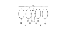
- FIG. 2 shows a simulation model of the power transmission system.
- the power transmission system 89 includes a power transmission device 90 and a power reception device 91, and the power transmission device 90 includes an electromagnetic induction coil 92 and a power transmission unit 93.
- the power transmission unit 93 includes a resonance coil 94 and a capacitor 95 provided in the resonance coil 94.
- the power receiving device 91 includes a power receiving unit 96 and an electromagnetic induction coil 97.
- the power receiving unit 96 includes a resonance coil 99 and a capacitor 98 connected to the resonance coil 99.
- the inductance of the resonance coil 94 is defined as an inductance Lt
- the capacitance of the capacitor 95 is defined as a capacitance C1.
- An inductance of the resonance coil 99 is an inductance Lr
- a capacitance of the capacitor 98 is a capacitance C2.
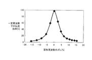
- the horizontal axis indicates the deviation (%) of the natural frequency
- the vertical axis indicates the transmission efficiency (%) at a constant frequency.
- the deviation (%) in the natural frequency is expressed by the following equation (3).
- the power transmission efficiency can be increased. Furthermore, the power transmission efficiency can be further improved by setting the natural frequency of each power transmission unit and the power receiving unit so that the absolute value of the deviation (%) of the natural frequency is 5% or less of the natural frequency of the power receiving unit 96. I understand that I can do it.
- simulation software electromagnetic field analysis software (JMAG: manufactured by JSOL Corporation) is employed.
- AC power is supplied to the electromagnetic induction coil 23 from the high frequency power driver 22.
- an alternating current also flows through the resonance coil 24 by electromagnetic induction.
- electric power is supplied to the electromagnetic induction coil 23 so that the frequency of the alternating current flowing through the resonance coil 24 becomes a specific frequency.
- the resonance coil 11 is disposed within a predetermined range from the resonance coil 24, and the resonance coil 11 receives electric power from an electromagnetic field formed around the resonance coil 24.
- so-called helical coils are employed for the resonance coil 11 and the resonance coil 24.
- a magnetic field that vibrates at a specific frequency is mainly formed around the resonance coil 24, and the resonance coil 11 receives electric power from the magnetic field.
- the “specific frequency magnetic field” typically has a relationship with the power transmission efficiency and the frequency of the current supplied to the resonance coil 24.
- the power transmission efficiency when power is transmitted from the resonance coil 24 to the resonance coil 11 varies depending on various factors such as the distance between the resonance coil 24 and the resonance coil 11.
- the natural frequency (resonance frequency) of the power transmission unit 28 and the power reception unit 27 is the natural frequency f0
- the frequency of the current supplied to the resonance coil 24 is the frequency f3
- the air gap between the resonance coil 11 and the resonance coil 24 is Air gap AG.
- FIG. 4 is a graph showing the relationship between the power transmission efficiency when the air gap AG is changed and the frequency f3 of the current supplied to the resonance coil 24 with the natural frequency f0 fixed.
- the efficiency curve L1 schematically shows the relationship between the power transmission efficiency when the air gap AG is small and the frequency f3 of the current supplied to the resonance coil 24.
- the efficiency curve L1 when the air gap AG is small, the peak of power transmission efficiency occurs at frequencies f4 and f5 (f4 ⁇ f5).
- the two peaks when the power transmission efficiency is increased change so as to approach each other.
- the peak of the power transmission efficiency is one, and the power transmission efficiency is increased when the frequency of the current supplied to the resonance coil 24 is the frequency f6. It becomes a peak.
- the peak of power transmission efficiency is reduced as shown by the efficiency curve L3.
- the following first method can be considered as a method for improving the power transmission efficiency.
- the power transmission unit 28 and the power reception unit are changed by changing the capacitances of the capacitors 25 and 19 while keeping the frequency of the current supplied to the resonance coil 24 shown in FIG. 27, a method of changing the characteristic of the power transmission efficiency with the terminal 27 can be considered.
- the capacitances of the capacitor 25 and the capacitor 19 are adjusted so that the power transmission efficiency reaches a peak in a state where the frequency of the current supplied to the resonance coil 24 is constant.
- the frequency of the current flowing through the resonance coil 24 and the resonance coil 11 is constant regardless of the size of the air gap AG.
- the second method is a method of adjusting the frequency of the current supplied to the resonance coil 24 based on the size of the air gap AG.
- the resonance coil 24 is supplied with a current having a frequency f4 or a frequency f5.
- the frequency characteristic becomes the efficiency curves L2 and L3
- a current having a frequency f6 is supplied to the resonance coil 24.
- the frequency of the current flowing through the resonance coil 24 and the resonance coil 11 is changed in accordance with the size of the air gap AG.
- the frequency of the current flowing through the resonance coil 24 is a fixed constant frequency
- the frequency flowing through the resonance coil 24 is a frequency that changes as appropriate depending on the air gap AG.
- a current having a specific frequency set so as to increase the power transmission efficiency is supplied to the resonance coil 24 by the first method, the second method, or the like.
- a magnetic field electromagnettic field
- the power reception unit 27 receives power from the power transmission unit 28 through a magnetic field that is formed between the power reception unit 27 and the power transmission unit 28 and vibrates at a specific frequency.
- the “magnetic field oscillating at a specific frequency” is not necessarily a magnetic field having a fixed frequency.
- the frequency of the current supplied to the resonance coil 24 is set, but the power transmission efficiency varies depending on other factors.
- the frequency of the current supplied to the resonance coil 24 may be adjusted based on other factors.
- FIG. 5 is a diagram showing the relationship between the distance from the current source (magnetic current source) and the strength of the electromagnetic field.
- the electromagnetic field is composed of three components.
- a curve k1 is a component inversely proportional to the distance from the wave source, and is referred to as a “radiating electric field”.
- a curve k2 is a component inversely proportional to the square of the distance from the wave source, and is referred to as an “induced electric field”.
- the curve k3 is a component that is inversely proportional to the cube of the distance from the wave source, and is referred to as an “electrostatic field”.
- the wavelength of the electromagnetic field is “ ⁇ ”
- the distance at which the “radiation electric field”, the “induction electric field”, and the “electrostatic field” are approximately equal to each other can be expressed as ⁇ / 2 ⁇ .
- the “electrostatic field” is a region where the intensity of the electromagnetic wave suddenly decreases with the distance from the wave source.
- the near field evanescent field
- Energy (electric power) is transmitted using this. That is, in the near field where the “electrostatic field” is dominant, the power transmission unit 28 and the power reception unit 27 (for example, a pair of LC resonance coils) having the same natural frequency are resonated, thereby transmitting from the power transmission unit 28 to the other power reception unit 27. Transmit energy (electric power). Since this “electrostatic field” does not propagate energy far away, the resonance method can transmit power with less energy loss than electromagnetic waves that transmit energy (electric power) by “radiant electric field” that propagates energy far away. it can.
- the power transmission device 41 is transmitted from the power transmission device 41 to the power reception device by causing the power transmission unit 28 and the power reception unit 27 to resonate with the electromagnetic field.
- the coupling coefficient ( ⁇ ) between the power transmission unit 28 and the power reception unit 27 is 0.1 or less. In general, in power transmission using electromagnetic induction, the coupling coefficient ( ⁇ ) between the power transmission unit and the power reception unit is close to 1.0.
- magnetic resonance coupling For example, “magnetic resonance coupling”, “magnetic field (magnetic field) resonance coupling”, “electromagnetic field (electromagnetic field) resonance coupling”, or “electric field (electromagnetic field) resonance coupling” in the power transmission of the present embodiment. Electric field) Resonant coupling.
- Electromagnetic field (electromagnetic field) resonance coupling means a coupling including any of “magnetic resonance coupling”, “magnetic field (magnetic field) resonance coupling”, and “electric field (electric field) resonance coupling”.
- the resonance coil 24 of the power transmission unit 28 and the resonance coil 11 of the power reception unit 27 described in this specification employ a coil-shaped antenna
- the power transmission unit 28 and the power reception unit 27 are mainly generated by a magnetic field.
- the power transmitting unit 28 and the power receiving unit 27 are “magnetic resonance coupled” or “magnetic field (magnetic field) resonant coupled”.
- an antenna such as a meander line can be used as the resonance coils 24 and 11.
- the power transmission unit 28 and the power reception unit 27 are mainly coupled by an electric field.
- the power transmission unit 28 and the power reception unit 27 are “electric field (electric field) resonance coupled”.
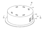
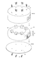
- FIG. 6 is a perspective view showing the power receiving device 40
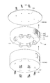
- FIG. 7 is an exploded perspective view of the power receiving device 40.
- the power receiving device 40 includes a housing 43 and a unit 46 accommodated in the housing 43.
- the housing 43 includes a shield 45 formed so that the lower surface is opened, and a lid portion 44 that closes the opening of the shield 45.
- the shield 45 is made of a metal material, and defines a region where an electromagnetic field formed around the resonance coil is formed.
- the shield 45 includes a top plate portion and a peripheral wall portion that hangs downward from the peripheral portion of the top plate portion. The electromagnetic field formed around the resonance coil is radiated downward.
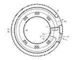
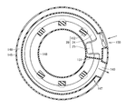
- FIG. 8 is a cross-sectional view of the power receiving device. 7 and 8, the unit 46 includes a power reception unit 27 and a cooling device 47 that cools the power reception unit 27.
- the cooling device 47 includes an annular cylindrical pipe portion 48, an exhaust port 49 formed on the peripheral surface of the pipe portion 48, a blower 50 provided on the peripheral surface of the pipe portion 48, and a pipe portion 48, and a partition member 51 formed in 48.
- the pipe part 48 is formed in a hollow shape, and the blower 50 supplies cooling air into the pipe part 48, and the air in the pipe part 48 is exhausted from the exhaust port 49.
- the blower 50 is connected to an opening formed in the shield 45, and the exhaust port 49 is connected to an opening formed in the shield 45.
- the partition member 51 is disposed between the blower 50 and the exhaust port 49, and is a member that partitions the inside of the pipe portion 48.
- the power receiving unit 27 is disposed in the tube unit 48.
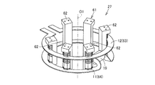
- FIG. 9 is a perspective view showing the power receiving unit 27.
- the power receiving unit 27 includes an electromagnetic induction coil 12, a resonance coil 11, a capacitor 19, and a holding unit 61.
- the electromagnetic induction coil 12 and the resonance coil 11 have approximately one turn.
- the electromagnetic induction coil 12 is formed by winding the coil wire 63 so as to surround the periphery of the center line O1.
- the resonance coil 11 is formed by winding the coil wire 64 so as to surround the periphery of the center line O1.
- FIG. 10 is a cross-sectional view showing the coil wire 63
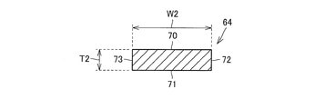
- FIG. 11 is a cross-sectional view showing the coil wire 64.
- the width W1 of the coil wire 63 is larger than the thickness T1.
- the coil wire 63 includes a main surface 65 and a main surface 66 arranged in the thickness direction, and includes a side surface 67 and a side surface 68 connected to the main surface 65 and the main surface 66 and arranged in the width direction.
- the electromagnetic induction coil 12 is formed by bending the coil wire 63 so that the side surface 67 is positioned on the inner peripheral side and the side surface 68 is positioned on the outer peripheral side. For this reason, the main surface 65 and the main surface 66 are arranged in the direction in which the center line O1 extends.
- the coil wire 64 has a width W2 larger than a thickness T2.
- Coil wire 64 includes main surface 70 and main surface 71 arranged in the thickness direction, and side surface 72 and side surface 73 formed to connect main surface 70 and main surface 71 and arranged in the width direction.
- the resonance coil 11 is formed such that the side surface 72 is located on the inner circumferential side and the side surface 73 is located on the outer circumferential side.
- the main surface 70 and the main surface 71 are arranged in the direction in which the center line O1 extends.
- the thickness of the coil wire will be described.
- the longest side portion of the peripheral portions of the cross section is the long side portion.
- the average value of the lengths in the direction perpendicular to the long side portion is taken as the thickness of the coil wire.
- the width is an average value of the lengths in the direction perpendicular to the thickness direction. For example, in the example shown in FIG.
- the cross section of the coil wire 64 in the direction perpendicular to the extending direction of the coil wire 64 has a rectangular shape.
- regulated by the main surface 70 and the main surface 71 turns into a long side part.
- the length in the direction perpendicular to main surface 70 or main surface 71 is the thickness of coil wire 64.
- the arrangement direction of the side surface 73 and the side surface 72 is a direction perpendicular to the main surface 70 and the main surface 71. For this reason, in the example shown in FIG. 11, the distance between the side surface 73 and the side surface 72 is the width of the coil wire 64.
- the resonance coil 11 and the electromagnetic induction coil 12 are formed by the coil wire 63 and the coil wire 64 having a square cross section
- the cross sectional shape of the coil wire forming the resonance coil 11 and the electromagnetic induction coil 12 is used.
- coil wires having various cross-sectional shapes can be employed. For example, polygonal shapes such as pentagons and hexagons, oval shapes, and elliptical shapes can be employed.
- the surface areas of the resonance coil 11 and the electromagnetic induction coil 12 can be increased as compared with the round wire coil having the same cross-sectional area.
- a high-frequency current flows through the resonance coil 11 and the electromagnetic induction coil 12.
- the current flows on the surface of each coil due to surface effects. For this reason, the resistance of each coil can be reduced by increasing the surface area of each coil as described above.
- the resonance coil 11 may be a multilayer coil.
- the area facing the center line O1 increases, and the stray capacitance formed in the resonance coil 11 can be increased.
- the holding unit 61 holds the electromagnetic induction coil 12 and the resonance coil 11, and the holding unit 61 includes a plurality of coil holding members 62.
- the coil holding member 62 is arranged inside the resonance coil 11 and the electromagnetic induction coil 12, and a plurality of the coil holding members 62 are arranged at intervals in the extending direction of the resonance coil 11 and the electromagnetic induction coil 12.
- the coil holding member 62 is disposed on the inner peripheral side of the resonance coil 11 and the electromagnetic induction coil 12
- the coil holding member 62 is disposed on the outer peripheral side of the resonance coil 11 and the electromagnetic induction coil 12.
- the power receiving unit 27 can be made compact.
- a plurality of coil holding members 62 may be alternately arranged on the inner peripheral side and the outer peripheral side of the resonance coil 11 and the electromagnetic induction coil 12.
- Both ends of the resonance coil 11 are drawn to the inside of the resonance coil 11, and a capacitor 19 is connected to the both ends.
- the power receiving unit 27 is made compact by disposing the capacitor 19 in the resonance coil 11.
- the upper end portion and the lower end portion of the coil holding member 62 are formed so as to protrude from the tube portion 48.
- Bolt holes are formed in the upper end surface and lower end surface of the coil holding member 62.
- a hole 57 is formed in the top plate portion of the shield 45 at a portion corresponding to the hole formed in the upper end portion of the coil holding member 62, and the lid portion 44 has a lower end portion of the coil holding member 62.
- a hole 58 is formed in a portion corresponding to the formed hole.
- the upper end portion of the coil holding member 62 is fixed to the top plate portion of the shield 45 by the bolt 55, and the lower end portion of the coil holding member 62 is fixed to the lid portion 44 by the bolt 56.
- the shield 45, the unit 46 (power receiving unit 27), and the lid unit 44 are integrated.
- the upper end portion of the coil holding member 62 is connected to the top plate portion of the shield 45, and the lower end portion of the coil holding member 62 is fixed to the lid portion 44. For this reason, the coil holding member 62 connects the top plate portion and the bottom surface portion of the casing 43, and the rigidity of the casing 43 is enhanced by the coil holding member 62.
- the housing 43 can be prevented from being deformed.
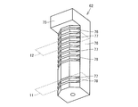
- FIG. 12 is a perspective view showing the coil holding member 62.
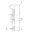
- FIG. 13 is a side view of the coil holding member 62 shown in FIG.
- the coil holding member 62 includes a base portion 75 and a column portion 76 connected to the base portion 75.
- the pillar portion 76 includes a main body portion 79 and a plurality of support portions 78 formed on the peripheral surface of the main body portion 79 and formed at intervals in the height direction of the main body portion 79.
- a groove portion 77 is formed between the support portions 78. Then, the resonance coil 11 and the electromagnetic induction coil 12 are fitted in the groove 77.
- the vehicle-side impedance can be adjusted by adjusting the distance between the resonance coil 11 and the electromagnetic induction coil 12.
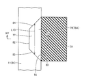
- FIG. 14 is a cross-sectional view taken along line XIV-XIV shown in FIG. As shown in FIG. 14, the support portion 78 is formed so as to protrude from the main body portion 79.
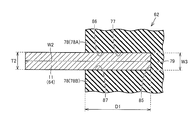
- FIG. 15 is a cross-sectional view taken along line XV-XV shown in FIG.
- the coil holding member 62 is adjacent to the groove portion 77 and supports the resonance coil 11, and a support portion 78 ⁇ / b> B disposed on the opposite side of the support portion 78 ⁇ / b> A with respect to the groove portion 77. including.
- the groove part 77 is formed between the two support parts 78A and 78B.
- the bottom portion 85 of the groove portion 77 is defined by the main body portion 79, and the inner side surfaces 86 and 87 of the groove portion 77 are defined by the support portions 78A and 78B.
- the depth D1 of the groove 77 extends in the width direction of the coil wire 64 forming the resonance coil 11, and the width W3 of the groove 77 extends in the thickness direction of the coil wire 64. Further, in FIG. 14, the groove 77 extends in the direction in which the resonance coil 11 extends.
- the depth D1 of the groove 77 is formed to be larger than the width W3.
- a position of the groove 77 that is closest to the winding center of the resonance coil 11 is defined as an opening of the groove 77.
- the bottom part 85 is a part which opposes the said opening part among the internal peripheral surfaces of the groove part 77.
- FIG. The depth D1 of the groove 77 is a distance from the opening to the bottom 85.
- the length of the groove 77 is the length in the direction in which the resonance coil 11 extends.
- the width of the groove 77 is the length in the thickness direction of the coil wire to be inserted.
- the coil holding member 62 is made of an insulating resin material. At the time of power transmission, a high voltage current flows through the resonance coil 11, and the resonance coil 11 becomes high temperature. The support portions 78A and 78B expand due to the high temperature of the resonance coil 11.
- the width W3 of the groove part 77 is reduced, and the surface pressure applied to the resonance coil 11 inserted into the groove part 77 from the support part 78A and the support part 78B is increased.
- the main body 79 when the main body 79 is heated, the main body 79 is deformed so that the depth D1 of the groove 77 is reduced.
- the width W3 of the groove portion 77 is smaller than the depth D1 of the groove portion 77, the width W3 is narrower than the deformation amount in which the depth D1 of the groove portion 77 is reduced by heating the coil holding member 62. The amount of deformation becomes larger.
- the width W2 of the resonance coil 11 is larger than the depth D1 of the groove 77, and the resonance coil 11 is provided so as to protrude from the groove 77. For this reason, as shown in FIG. 8, the resonance coil 11 is satisfactorily cooled by the cooling air introduced from the blower 50 into the pipe portion 48.
- the support part 78 when the support part 78 is viewed from a position away from the support part 78 in the direction in which the support parts 78 are arranged, the support part 78 is formed to have a trapezoidal shape.
- the support portion 78 includes a long side portion 80 connected to the main body portion 79, side portions 83 and 84, and a short side portion 82.
- the support portion 78A is formed so that the length L10 in the extending direction of the resonance coil 11 increases as it goes toward the bottom portion 85 of the groove portion 77. That is, since the side portion 83 and the side portion 84 of the support portion 78A are formed in a tapered shape, the exposed area of the resonance coil 11 is increased. As a result, the area where the resonance coil 11 is cooled by the cooling air increases, and the resonance coil 11 is cooled well. In addition, you may form the side part 83 and the side part 84 so that it may curve.
- the resonance coil 11 can be easily inserted into the groove portion 77, and the assembly efficiency can be improved. .
- FIG. 16 is a perspective view showing the power transmission device 41
- FIG. 17 is an exploded perspective view of the power transmission device 41.
- the power transmission device 41 includes a housing 143 and a unit 146 accommodated in the housing 143.
- the housing 143 includes a shield 145 formed so that the upper surface is open, and a lid 144 that closes the opening of the shield 145.
- the shield 145 is formed of a metal material, and defines a region where an electromagnetic field formed around the resonance coil is formed.
- the shield 145 includes a bottom surface portion and a peripheral wall portion formed so as to rise from the peripheral edge portion of the bottom surface portion. The electromagnetic field formed around the resonance coil is radiated upward.
- FIG. 18 is a cross-sectional view of the power transmission device 41. 17 and 18, the unit 146 includes a power transmission unit 28 and a cooling device 147 that cools the power transmission unit 28.
- the cooling device 147 includes a tubular tube portion 148 formed in an annular shape, an exhaust port 149 formed in the peripheral surface of the tube portion 148, a blower 150 provided on the peripheral surface of the tube portion 148, and a tube portion And a partition member 151 formed in 148.
- the pipe part 148 is formed in a hollow shape, and the blower 150 supplies cooling air into the pipe part 148, and the air in the pipe part 148 is exhausted from the exhaust port 149.
- the blower 150 is connected to an opening formed in the shield 145, and the exhaust port 149 is connected to an opening formed in the shield 145.
- the partition member 151 is a member that is disposed between the blower 150 and the exhaust port 149 and partitions the inside of the pipe portion 148.
- a power transmission unit 28 is disposed in the pipe unit 148.
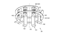
- FIG. 19 is a perspective view showing the power transmission unit 28.
- the power transmission unit 28 includes an electromagnetic induction coil 23, a resonance coil 24, a capacitor 23, and a holding unit 161.
- the electromagnetic induction coil 23 and the resonance coil 24 have approximately one turn.
- the electromagnetic induction coil 23 is formed by winding the coil wire 163 so as to surround the periphery of the center line O2.
- the resonance coil 24 is formed by winding the coil wire 164 so as to surround the periphery of the center line O2.
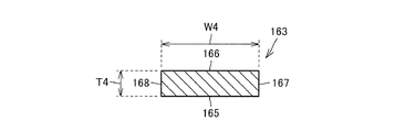
- FIG. 20 is a cross-sectional view showing the coil wire 163
- FIG. 21 is a cross-sectional view showing the coil wire 164.
- the width W4 of the coil wire 163 is larger than the thickness T4.
- Coil wire 163 includes main surface 165 and main surface 166 arranged in the thickness direction, and includes side surface 167 and side surface 168 arranged in the width direction while connecting main surface 165 and main surface 166.
- the thickness of the coil wire will be described.
- the longest side portion of the peripheral portions of the cross section is the long side portion.
- the average value of the lengths in the direction perpendicular to the long side portion is taken as the thickness of the coil wire.
- the width is an average value of the lengths in the direction perpendicular to the thickness direction.
- the cross section of the coil wire 164 in the direction perpendicular to the extending direction of the coil wire 164 has a rectangular shape.
- regulated by the main surface 170 and the main surface 171 becomes a long side part.
- the length in the direction perpendicular to main surface 170 or main surface 171 is the thickness of coil wire 164.
- the arrangement direction of side surface 173 and side surface 172 is a direction perpendicular to main surface 170 and main surface 171. For this reason, in the example shown in FIG. 21, the distance between the side surface 173 and the side surface 172 is the width of the coil wire 164.
- the electromagnetic induction coil 23 is formed by bending the coil wire 163 so that the side surface 167 is positioned on the inner peripheral side and the side surface 168 is positioned on the outer peripheral side. For this reason, main surface 165 and main surface 166 are arranged in the direction in which center line O2 extends.
- the coil wire 164 has a width W5 larger than a thickness T5.
- Coil wire 164 includes main surface 170 and main surface 171 arranged in the thickness direction, and side surface 172 and side surface 173 formed so as to connect main surface 170 and main surface 171 and arranged in the width direction.
- the resonance coil 24 is formed such that the side surface 172 is positioned on the inner peripheral side and the side surface 173 is positioned on the outer peripheral side.
- Main surface 170 and main surface 171 are arranged in the direction in which center line O2 extends.
- the resonance coil 24 and the electromagnetic induction coil 23 are formed by the coil wire 163 and the coil wire 164 having a square cross section, but the cross sectional shape of the coil wire forming the resonance coil 24 and the electromagnetic induction coil 23 is used.
- various cross-sectional shapes can be employed. For example, polygonal shapes such as pentagons and hexagons, oval shapes, and elliptical shapes can be employed.
- the surface areas of the resonance coil 24 and the electromagnetic induction coil 23 can be increased as compared with the round wire coils having the same cross-sectional area.
- a high frequency current flows through the resonance coil 24 and the electromagnetic induction coil 23.
- the current flows on the surface of each coil due to surface effects. For this reason, the resistance of each coil can be reduced by increasing the surface area of each coil as described above.
- the resonance coil 24 may be a multi-layer coil.
- the area facing the center line O2 is increased, and the stray capacitance formed in the resonance coil 24 can be increased.
- the holding unit 161 holds the electromagnetic induction coil 23 and the resonance coil 24, and the holding unit 161 includes a plurality of coil holding members 162.
- the coil holding member 162 is arranged inside the resonance coil 24 and the electromagnetic induction coil 23, and a plurality of the coil holding members 162 are arranged at intervals in the extending direction of the resonance coil 24 and the electromagnetic induction coil 23.
- the coil holding member 162 is disposed on the inner peripheral side of the resonance coil 24 and the electromagnetic induction coil 23
- the coil holding member 162 is disposed on the outer peripheral side of the resonance coil 24 and the electromagnetic induction coil 23.
- the power transmission unit 28 can be made compact.
- the plurality of coil holding members 162 may be alternately arranged on the inner peripheral side and the outer peripheral side of the resonance coil 24 and the electromagnetic induction coil 23.
- Both ends of the resonance coil 24 are drawn to the inside of the resonance coil 24, and the capacitor 23 is connected to the both ends.
- the power transmission unit 28 is made compact by arranging the capacitor 23 in the resonance coil 24.
- the upper end portion and the lower end portion of the coil holding member 162 are formed so as to protrude from the tube portion 148.
- a bolt hole is formed in the upper end surface and the lower end surface of the coil holding member 162.
- a hole 157 is formed in the bottom surface of the shield 145 in a portion corresponding to the hole formed in the lower end of the coil holding member 162, and the lid 144 is formed in the upper end of the coil holding member 162.
- a hole 158 is formed in a portion corresponding to the formed hole.
- the lower end portion of the coil holding member 162 is fixed to the bottom surface portion of the shield 145 by the bolt 155, and the upper end portion of the coil holding member 162 is fixed to the lid portion 144 by the bolt 156.
- the shield 145, the unit 146 (power transmission unit 28), and the lid 144 are integrated.
- the lower end portion of the coil holding member 162 is connected to the bottom surface portion of the shield 145, and the upper end portion of the coil holding member 162 is fixed to the lid portion 144.
- the coil holding member 162 connects the bottom surface portion of the housing 143 and the top plate portion, and the rigidity of the housing 143 is enhanced by the coil holding member 162.
- the housing 143 can be prevented from being deformed.
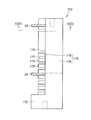
- FIG. 22 is a perspective view showing the coil holding member 162.
- 23 is a side view of the coil holding member 162 shown in FIG.
- the coil holding member 162 includes a base portion 175 and a column portion 176 connected to the base portion 175.
- the column part 176 includes a main body part 179 and a plurality of support parts 178 formed on the peripheral surface of the main body part 179 and formed at intervals in the height direction of the main body part 179.
- a groove portion 177 is formed between the support portions 178. Then, the resonance coil 24 and the electromagnetic induction coil 23 are fitted in the groove portion 177.
- the vehicle-side impedance can be adjusted by adjusting the distance between the resonance coil 24 and the electromagnetic induction coil 23.
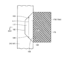
- FIG. 24 is a sectional view taken along line XXIV-XXIV shown in FIG. As shown in FIG. 24, the support portion 178 is formed so as to protrude from the main body portion 179.
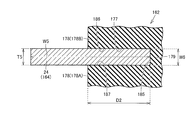
- FIG. 25 is a cross-sectional view taken along line XXV-XXV shown in FIG.
- the coil holding member 162 is adjacent to the groove 177 and supports the resonance coil 24, and a support 178A disposed on the opposite side of the support 178A with respect to the groove 177. including.
- the groove part 177 is formed between the two support parts 178A and 178B.
- the bottom portion 185 of the groove portion 177 is defined by the main body portion 179, and the inner side surfaces 86 and 87 of the groove portion 177 are defined by the support portions 178A and 178B.
- the depth D2 of the groove 177 extends in the width direction of the coil wire 164 forming the resonance coil 24, and the width W6 of the groove 177 extends in the thickness direction of the coil wire 164. Further, in FIG. 24, the groove 177 extends in the direction in which the resonance coil 24 extends.
- the depth D2 of the groove 177 is formed to be larger than the width W6.
- the position of the groove 177 closest to the winding center of the resonance coil 24 is defined as the opening of the groove 177.
- the bottom part 185 is a part which opposes the said opening part among the internal peripheral surfaces of the groove part 177.
- the depth of the groove 177 is the distance from the opening to the bottom 185.
- the length of the groove 177 is the length in the direction in which the resonance coil 24 extends.
- the width of the groove 177 is the length in the thickness direction of the coil wire to be inserted.
- the coil holding member 162 is made of an insulating resin material. At the time of power transmission, a high voltage current flows through the resonance coil 24 and the resonance coil 24 becomes high temperature. The support portions 178A and 178B expand when the resonance coil 24 becomes high temperature.
- the width W6 of the groove 177 is reduced, and the surface pressure applied to the resonance coil 24 inserted into the groove 177 from the support 178A and the support 1178B is increased.
- the main body part 179 when the main body part 179 is heated, the main body part 179 is deformed so that the depth D2 of the groove part 177 becomes small.
- the width W6 of the groove portion 177 is smaller than the depth D2 of the groove portion 177, the width W6 is narrower than the deformation amount in which the depth D2 of the groove portion 177 is reduced by heating the coil holding member 162. The amount of deformation becomes larger.
- the width W5 of the resonance coil 24 is larger than the depth D2 of the groove portion 177, and the resonance coil 24 is provided so as to protrude from the groove portion 177. For this reason, as shown in FIG. 18, the resonance coil 24 is satisfactorily cooled by the cooling air introduced from the blower 150 into the pipe portion 148.
- the support portion 178 when the support portion 178 is viewed from a position away from the support portion 178 in the direction in which the support portions 178 are arranged, the support portion 178 is formed in a trapezoidal shape. Specifically, the support portion 178 includes a long side portion 180 connected to the main body portion 179, side portions 183 and 184, and a short side portion 182.
- the support portion 178A is formed such that the length L11 in the extending direction of the resonance coil 24 increases toward the bottom portion 185 of the groove portion 177. That is, since the side portion 183 and the side portion 184 of the support portion 178A are formed in a tapered shape, the exposed area of the resonance coil 24 is increased. As a result, the area where the resonance coil 24 is cooled by the cooling air increases, and the resonance coil 24 is cooled well. Note that the side part 183 and the side part 184 may be formed to be curved.
- the resonance coil 24 can be easily inserted into the groove portion 177, and the assembly efficiency can be improved. .
- the present invention can be applied to a power receiving device, a power transmission device, and a power transmission system.
Landscapes
- Engineering & Computer Science (AREA)
- Power Engineering (AREA)
- Computer Networks & Wireless Communication (AREA)
- Transportation (AREA)
- Mechanical Engineering (AREA)
- Physics & Mathematics (AREA)
- Electromagnetism (AREA)
- Current-Collector Devices For Electrically Propelled Vehicles (AREA)
- Electric Propulsion And Braking For Vehicles (AREA)
- Coils Of Transformers For General Uses (AREA)
Abstract
Description
好ましくは、上記第1コイル保持部材は、第1溝部に対して第1溝部の幅方向に隣り合い、受電コイルを支持する第1支持部と、第1溝部に対して第1支持部と反対側に位置し、受電コイルを支持する第2支持部とを含む。上記第1支持部と第2支持部との少なくとも一方は、第1溝部の底部に向かうにつれて、受電コイルの延びる方向の長さが長くなるように形成される。
好ましくは、上記受電部は、受電部と送電部の間に形成され、かつ特定の周波数で振動する磁界と、受電部と送電部の間に形成され、かつ特定の周波数で振動する電界との少なくとも一方を通じて送電部から電力を受電する。
好ましくは、上記第2コイル保持部材は、第2溝部に対して第2溝部の幅方向に隣り合い、送電コイルを支持する第3支持部と、第2溝部に対して第3支持部と反対側に位置し、送電コイルを支持する第4支持部とを含む。
好ましくは、上記送電コイルの両端は、送電コイルの内側に引き出される。上記送電コイルの両端に接続されたキャパシタをさらに備える。
好ましくは、上記送電部は、受電部と送電部の間に形成され、かつ特定の周波数で振動する磁界と、受電部と送電部の間に形成され、かつ特定の周波数で振動する電界との少なくとも一方を通じて、受電部に電力を送電する。
好ましくは、上記受電部は、受電部と送電部の間に形成され、かつ特定の周波数で振動する磁界と、受電部と送電部の間に形成され、かつ特定の周波数で振動する電界との少なくとも一方を通じて送電部から電力を受電する。
f2=1/{2π(Lr×C2)1/2}・・・(2)
ここで、インダクタンスLrおよびキャパシタンスC1,C2を固定して、インダクタンスLtのみを変化させた場合において、送電部93および受電部96の固有周波数のズレと、電力伝送効率との関係を図3に示す。なお、このシミュレーションにおいては、共鳴コイル94および共鳴コイル99の相対的な位置関係は固定した状態であって、さらに、送電部93に供給される電流の周波数は一定である。
図3からも明らかなように、固有周波数のズレ(%)が±0%の場合には、電力伝送効率は、100%となる。固有周波数のズレ(%)が±5%の場合には、電力伝送効率は、40%となる。固有周波数のズレ(%)が±10%の場合には、電力伝送効率は、10%となる。固有周波数のズレ(%)が±15%の場合には、電力伝送効率は、5%となる。すなわち、固有周波数のズレ(%)の絶対値(固有周波数の差)が、受電部96の固有周波数の10%以下の範囲となるように各送電部および受電部の固有周波数を設定することで電力伝送効率を高めることができることがわかる。さらに、固有周波数のズレ(%)の絶対値が受電部96の固有周波数の5%以下となるように、各送電部および受電部の固有周波数を設定することで電力伝送効率をより高めることができることがわかる。なお、シミュレーションソフトしては、電磁界解析ソフトウェア(JMAG:株式会社JSOL製)を採用している。
図1において、電磁誘導コイル23には、高周波電力ドライバ22から交流電力が供給される。電磁誘導コイル23に所定の交流電流が流れると、電磁誘導によって共鳴コイル24にも交流電流が流れる。この際、共鳴コイル24を流れる交流電流の周波数が特定の周波数となるように、電磁誘導コイル23に電力が供給されている。
Claims (24)
- 間隔をあけて配置された送電部(28)から非接触で電力を受電する受電部(27)と、
前記受電部(27)を保持する第1保持ユニット(61)と、
を備え、
前記受電部(27)は、受電コイル(11)を含み、
前記受電コイル(11)は、幅が厚さよりも大きい第1コイル線(64)を巻回して形成され、
前記第1保持ユニット(61)は、前記受電コイル(11)の延びる方向に延び、前記受電コイル(11)を受け入れる第1溝部(77)が形成された複数の第1コイル保持部材(62)を含み、
前記第1溝部(77)の少なくとも一部は、前記第1コイル線(64)の幅方向に延びる前記第1溝部(77)の深さが、前記第1コイル線(64)の厚さ方向に延びる前記第1溝部(77)の幅よりも大きくなるように形成された、受電装置。 - 前記第1コイル線(64)の幅は、前記第1溝部(77)の深さよりも大きい、請求項1に記載の受電装置。
- 前記第1コイル保持部材(62)は、前記第1溝部(77)に対して前記第1溝部(77)の幅方向に隣り合い、前記受電コイル(11)を支持する第1支持部(78A)と、前記第1溝部(77)に対して前記第1支持部(78A)と反対側に位置し、前記受電コイル(11)を支持する第2支持部(78B)とを含み、
前記第1支持部(78A)と前記第2支持部(78B)との少なくとも一方は、前記第1溝部(77)の底部に向かうにつれて、前記受電コイル(11)の延びる方向の長さが長くなるように形成された、請求項1に記載の受電装置。 - 前記第1コイル保持部材(62)は、柱状に形成され、前記第1溝部(77)は、前記第1コイル保持部材(62)の高さ方向に間隔をあけて複数形成された、請求項1に記載の受電装置。
- 前記第1コイル保持部材(62)は、前記受電コイル(11)の内側に配置されると共に、前記受電コイル(11)に沿って間隔をあけて配置された、請求項1に記載の受電装置。
- 前記受電コイル(11)の両端は、前記受電コイル(11)の内側に引き出され、
前記受電コイル(11)の両端に接続されたキャパシタをさらに備えた、請求項5に記載の受電装置。 - 前記受電部(27)および前記第1保持ユニット(61)を内部に収容する第1収容ケース(43)をさらに備え、
前記第1収容ケース(43)は、天板部と、前記天板部と対向する底面部と、前記天板部と前記底面部とを接続する周壁部とを含み、
前記第1コイル保持部材(62)は、前記天板部と前記底面部とに接続された、請求項1に記載の受電装置。 - 前記送電部(28)の固有周波数と前記受電部(27)の固有周波数との差は、前記受電部(27)の固有周波数の10%以下である、請求項1に記載の受電装置。
- 前記受電部(27)と前記送電部(28)との結合係数は、0.1以下である、請求項1に記載の受電装置。
- 前記受電部(27)は、前記受電部(27)と前記送電部(28)の間に形成され、かつ特定の周波数で振動する磁界と、前記受電部(27)と前記送電部(28)の間に形成され、かつ特定の周波数で振動する電界との少なくとも一方を通じて前記送電部(28)から電力を受電する、請求項1に記載の受電装置。
- 間隔をあけて配置された受電部(27)に非接触で電力を送電する送電部(28)と、
前記送電部(28)を保持する第2保持ユニット(161)と、
を備え、
前記送電部(28)は、送電コイル(24)を含み、
前記送電コイル(24)は、幅が厚さよりも大きい第2コイル線(164)を巻回して形成され、
前記第2保持ユニット(161)は、前記送電コイル(24)の延びる方向に延び、前記送電コイル(24)を受け入れる第2溝部(177)が形成された複数の第2コイル保持部材(162)を含み、
前記第2溝部(177)の少なくとも一部は、前記第2コイル線(164)の幅方向に延びる前記第2溝部(177)の深さが、前記第2コイル線(164)の厚さ方向に延びる前記第2溝部(177)の幅よりも大きくなるように形成された、送電装置。 - 前記第2コイル線(164)の幅は、前記第2溝部(177)の深さよりも大きい、請求項11に記載の送電装置。
- 前記第2コイル保持部材(162)は、前記第2溝部(177)に対して前記第2溝部(177)の幅方向に隣り合い、前記送電コイル(24)を支持する第3支持部(178A)と、前記第2溝部(177)に対して前記第3支持部(178A)と反対側に位置し、前記送電コイル(24)を支持する第4支持部(178B)とを含み、
前記第3支持部(178A)と前記第4支持部(178B)との少なくとも一方は、前記第2溝部(177)の底部に向かうにつれて、前記送電コイル(24)の延びる方向の長さが長くなるように形成された、請求項11に記載の送電装置。 - 前記第2コイル保持部材(162)は、柱状に形成され、前記第2溝部(177)は、前記第2コイル保持部材(162)の高さ方向に間隔をあけて複数形成された、請求項11に記載の送電装置。
- 前記第2コイル保持部材(162)は、前記送電コイル(24)の内側に配置された、請求項11に記載の送電装置。
- 前記送電コイル(24)の両端は、前記送電コイル(24)の内側に引き出され、
前記送電コイル(24)の両端に接続されたキャパシタをさらに備えた、請求項15に記載の送電装置。 - 前記送電部(28)および前記第2保持ユニット(161)を内部に収容する第2収容ケース(143)をさらに備え、
前記第2収容ケース(143)は、天板部と、前記天板部と対向する底面部と、前記天板部と前記底面部とを接続する周壁部とを含み、
前記第2コイル保持部材(162)は、前記天板部と前記底面部とに接続された、請求項11に記載の送電装置。 - 前記送電部(28)の固有周波数と前記受電部(27)の固有周波数との差は、前記受電部(27)の固有周波数の10%以下である、請求項11に記載の送電装置。
- 前記受電部(27)と前記送電部(28)との結合係数は、0.1以下である、請求項11に記載の送電装置。
- 前記送電部(28)は、前記受電部(27)と前記送電部(28)の間に形成され、かつ特定の周波数で振動する磁界と、前記受電部(27)と前記送電部(28)の間に形成され、かつ特定の周波数で振動する電界との少なくとも一方を通じて、前記受電部(27)に電力を送電する、請求項11に記載の送電装置。
- 送電部(28)を含む送電装置と、
前記送電装置から非接触で電力を受電する受電装置と、
を備え、
前記受電装置は、前記送電部(28)から非接触で電力を受電する受電部(27)と、前記受電部(27)を保持する第1保持ユニット(61)とを含み、
前記送電装置は、前記送電部(28)を保持する第2保持ユニット(161)を含み、
前記受電部(27)は、受電コイル(11)を含み、
前記受電コイル(11)は、幅が厚さよりも大きい第1コイル線(64)を巻回して形成され、
前記第1保持ユニット(61)は、前記受電コイル(11)の延びる方向に延び、前記受電コイル(11)を受け入れる第1溝部が形成された複数の第1コイル保持部材(62)を含み、
前記第1溝部の少なくとも一部は、前記第1コイル線(64)の幅方向に延びる前記第1溝部の深さが、前記第1コイル線(64)の厚さ方向に延びる前記第1溝部の幅よりも大きく、
前記送電部(28)は、送電コイル(24)を含み、
前記送電コイル(24)は、幅が厚さよりも大きい第2コイル線(164)を巻回して形成され、
前記第2保持ユニット(161)は、前記送電コイル(24)の延びる方向に延び、前記送電コイル(24)を受け入れる第2溝部が形成された複数の第2コイル保持部材(162)を含み、
前記第2溝部の少なくとも一部は、前記第2コイル線(164)の幅方向に延びる前記第2溝部の深さが、前記第2コイル線(164)の厚さ方向に延びる前記第2溝部の幅よりも大きい、電力伝送システム。 - 前記送電部(28)の固有周波数と前記受電部(27)の固有周波数との差は、前記受電部(27)の固有周波数の10%以下である、請求項21に記載の電力伝送システム。
- 前記受電部(27)と前記送電部(28)との結合係数は、0.1以下である、請求項21に記載の電力伝送システム。
- 前記受電部(27)は、前記受電部(27)と前記送電部(28)の間に形成され、かつ特定の周波数で振動する磁界と、前記受電部(27)と前記送電部(28)の間に形成され、かつ特定の周波数で振動する電界との少なくとも一方を通じて前記送電部(28)から電力を受電する、請求項21に記載の電力伝送システム。
Priority Applications (5)
| Application Number | Priority Date | Filing Date | Title |
|---|---|---|---|
| EP11873664.4A EP2765584A4 (en) | 2011-10-04 | 2011-10-04 | POWER RECEIVING DEVICE, POWER TRANSMISSION DEVICE AND POWER TRANSMISSION SYSTEM |
| JP2013537310A JP5888335B2 (ja) | 2011-10-04 | 2011-10-04 | 受電装置、送電装置および電力伝送システム |
| US14/348,943 US20140232202A1 (en) | 2011-10-04 | 2011-10-04 | Power reception device, power transmission device and power transfer system |
| PCT/JP2011/072839 WO2013051105A1 (ja) | 2011-10-04 | 2011-10-04 | 受電装置、送電装置および電力伝送システム |
| CN201180073989.3A CN103843084A (zh) | 2011-10-04 | 2011-10-04 | 受电装置、送电装置以及电力传输系统 |
Applications Claiming Priority (1)
| Application Number | Priority Date | Filing Date | Title |
|---|---|---|---|
| PCT/JP2011/072839 WO2013051105A1 (ja) | 2011-10-04 | 2011-10-04 | 受電装置、送電装置および電力伝送システム |
Publications (1)
| Publication Number | Publication Date |
|---|---|
| WO2013051105A1 true WO2013051105A1 (ja) | 2013-04-11 |
Family
ID=48043297
Family Applications (1)
| Application Number | Title | Priority Date | Filing Date |
|---|---|---|---|
| PCT/JP2011/072839 Ceased WO2013051105A1 (ja) | 2011-10-04 | 2011-10-04 | 受電装置、送電装置および電力伝送システム |
Country Status (5)
| Country | Link |
|---|---|
| US (1) | US20140232202A1 (ja) |
| EP (1) | EP2765584A4 (ja) |
| JP (1) | JP5888335B2 (ja) |
| CN (1) | CN103843084A (ja) |
| WO (1) | WO2013051105A1 (ja) |
Cited By (2)
| Publication number | Priority date | Publication date | Assignee | Title |
|---|---|---|---|---|
| JP2014060374A (ja) * | 2012-09-19 | 2014-04-03 | Kojima Press Industry Co Ltd | 給電ユニット |
| WO2021131608A1 (ja) * | 2019-12-27 | 2021-07-01 | Tdk株式会社 | 異物検出装置、送電装置、受電装置および電力伝送システム |
Families Citing this family (7)
| Publication number | Priority date | Publication date | Assignee | Title |
|---|---|---|---|---|
| JP6009174B2 (ja) * | 2012-02-23 | 2016-10-19 | 矢崎総業株式会社 | 非接触給電システム用シールドケース及び非接触給電システム |
| EP2996221B1 (en) | 2013-05-10 | 2017-10-04 | IHI Corporation | Contactless power supply system |
| US10277069B2 (en) * | 2014-08-01 | 2019-04-30 | Samsung EIectro-Mechanics Co., Ltd. | Wireless power transmitter |
| JP6502056B2 (ja) * | 2014-10-22 | 2019-04-17 | 日本圧着端子製造株式会社 | 電気的接続装置 |
| JP6287993B2 (ja) * | 2015-08-04 | 2018-03-07 | トヨタ自動車株式会社 | 車両 |
| US20170324281A1 (en) * | 2016-05-06 | 2017-11-09 | Ningbo Weie Electronics Technology Ltd. | Wireless power trnsfer device |
| GB2595244B (en) * | 2020-05-18 | 2022-05-25 | Inductive Power Projection Ltd | Wireless power transfer |
Citations (7)
| Publication number | Priority date | Publication date | Assignee | Title |
|---|---|---|---|---|
| JPS5137951Y2 (ja) * | 1971-02-26 | 1976-09-17 | ||
| JPH11329862A (ja) * | 1998-05-08 | 1999-11-30 | Tdk Corp | 箱形ノイズフィルタ |
| JP2006147927A (ja) * | 2004-11-22 | 2006-06-08 | Ushio Inc | トランス |
| JP2010087353A (ja) | 2008-10-01 | 2010-04-15 | Toyota Motor Corp | 非接触電力伝達装置、非接触電力伝達装置の製造方法および非接触電力伝達装置を備えた車両 |
| JP2010267917A (ja) * | 2009-05-18 | 2010-11-25 | Toyota Motor Corp | コイルユニット、非接触電力伝送装置、非接触給電システムおよび電動車両 |
| JP2010268660A (ja) * | 2009-05-18 | 2010-11-25 | Toyota Motor Corp | 非接触電力伝達装置、車両および非接触電力伝達システム |
| JP2011204836A (ja) * | 2010-03-25 | 2011-10-13 | Toyota Motor Corp | コイルユニット、非接触電力受電装置、非接触電力送電装置、および車両 |
Family Cites Families (7)
| Publication number | Priority date | Publication date | Assignee | Title |
|---|---|---|---|---|
| JPS5137951A (ja) * | 1974-09-27 | 1976-03-30 | Niibori Sangyo Jugengaisha | |
| JPS5678225U (ja) * | 1979-11-07 | 1981-06-25 | ||
| JPS6367217U (ja) * | 1986-10-22 | 1988-05-06 | ||
| JPH0657978B2 (ja) * | 1990-11-30 | 1994-08-03 | ユアサ建材工業株式会社 | 多方向継手 |
| GB2262393B (en) * | 1991-11-25 | 1996-04-10 | Sumitomo Wall Systems Ltd | A wire harness including a wire spacing device |
| JPH08264338A (ja) * | 1995-03-28 | 1996-10-11 | Matsushita Electric Works Ltd | 電磁装置 |
| US8994221B2 (en) * | 2010-06-01 | 2015-03-31 | University Of Maryland | Method and system for long range wireless power transfer |
-
2011
- 2011-10-04 WO PCT/JP2011/072839 patent/WO2013051105A1/ja not_active Ceased
- 2011-10-04 JP JP2013537310A patent/JP5888335B2/ja active Active
- 2011-10-04 EP EP11873664.4A patent/EP2765584A4/en not_active Withdrawn
- 2011-10-04 CN CN201180073989.3A patent/CN103843084A/zh active Pending
- 2011-10-04 US US14/348,943 patent/US20140232202A1/en not_active Abandoned
Patent Citations (7)
| Publication number | Priority date | Publication date | Assignee | Title |
|---|---|---|---|---|
| JPS5137951Y2 (ja) * | 1971-02-26 | 1976-09-17 | ||
| JPH11329862A (ja) * | 1998-05-08 | 1999-11-30 | Tdk Corp | 箱形ノイズフィルタ |
| JP2006147927A (ja) * | 2004-11-22 | 2006-06-08 | Ushio Inc | トランス |
| JP2010087353A (ja) | 2008-10-01 | 2010-04-15 | Toyota Motor Corp | 非接触電力伝達装置、非接触電力伝達装置の製造方法および非接触電力伝達装置を備えた車両 |
| JP2010267917A (ja) * | 2009-05-18 | 2010-11-25 | Toyota Motor Corp | コイルユニット、非接触電力伝送装置、非接触給電システムおよび電動車両 |
| JP2010268660A (ja) * | 2009-05-18 | 2010-11-25 | Toyota Motor Corp | 非接触電力伝達装置、車両および非接触電力伝達システム |
| JP2011204836A (ja) * | 2010-03-25 | 2011-10-13 | Toyota Motor Corp | コイルユニット、非接触電力受電装置、非接触電力送電装置、および車両 |
Non-Patent Citations (1)
| Title |
|---|
| See also references of EP2765584A4 |
Cited By (3)
| Publication number | Priority date | Publication date | Assignee | Title |
|---|---|---|---|---|
| JP2014060374A (ja) * | 2012-09-19 | 2014-04-03 | Kojima Press Industry Co Ltd | 給電ユニット |
| WO2021131608A1 (ja) * | 2019-12-27 | 2021-07-01 | Tdk株式会社 | 異物検出装置、送電装置、受電装置および電力伝送システム |
| US11833916B2 (en) | 2019-12-27 | 2023-12-05 | Tdk Corporation | Foreign substance detection device, electricity transmission device, electricity reception device, and electric power transmission system |
Also Published As
| Publication number | Publication date |
|---|---|
| CN103843084A (zh) | 2014-06-04 |
| JP5888335B2 (ja) | 2016-03-22 |
| JPWO2013051105A1 (ja) | 2015-03-30 |
| EP2765584A4 (en) | 2015-08-12 |
| US20140232202A1 (en) | 2014-08-21 |
| EP2765584A1 (en) | 2014-08-13 |
Similar Documents
| Publication | Publication Date | Title |
|---|---|---|
| JP5888335B2 (ja) | 受電装置、送電装置および電力伝送システム | |
| JP5786949B2 (ja) | 受電装置、送電装置および電力伝送システム | |
| JP5839120B2 (ja) | 受電装置および送電装置 | |
| JP5682712B2 (ja) | 受電装置、送電装置および電力伝送システム | |
| JP5890191B2 (ja) | 送電装置、受電装置、および電力伝送システム | |
| JP5700137B2 (ja) | 送電装置、受電装置、および電力伝送システム | |
| JP5810944B2 (ja) | 車両および電力伝送システム | |
| JP6126013B2 (ja) | 車両 | |
| JP5846302B2 (ja) | 車両 | |
| US20150008877A1 (en) | Vehicle | |
| JP2013132171A (ja) | 送電装置、受電装置、および電力伝送システム |
Legal Events
| Date | Code | Title | Description |
|---|---|---|---|
| 121 | Ep: the epo has been informed by wipo that ep was designated in this application |
Ref document number: 11873664 Country of ref document: EP Kind code of ref document: A1 |
|
| ENP | Entry into the national phase |
Ref document number: 2013537310 Country of ref document: JP Kind code of ref document: A |
|
| WWE | Wipo information: entry into national phase |
Ref document number: 14348943 Country of ref document: US |
|
| NENP | Non-entry into the national phase |
Ref country code: DE |
|
| WWE | Wipo information: entry into national phase |
Ref document number: 2011873664 Country of ref document: EP |