WO2013051196A1 - 分布型光ファイバ音波検出装置 - Google Patents
分布型光ファイバ音波検出装置 Download PDFInfo
- Publication number
- WO2013051196A1 WO2013051196A1 PCT/JP2012/005736 JP2012005736W WO2013051196A1 WO 2013051196 A1 WO2013051196 A1 WO 2013051196A1 JP 2012005736 W JP2012005736 W JP 2012005736W WO 2013051196 A1 WO2013051196 A1 WO 2013051196A1
- Authority
- WO
- WIPO (PCT)
- Prior art keywords
- pulse
- light
- unit
- optical fiber
- phase
- Prior art date
- Legal status (The legal status is an assumption and is not a legal conclusion. Google has not performed a legal analysis and makes no representation as to the accuracy of the status listed.)
- Ceased
Links
Images


Classifications
-
- H—ELECTRICITY
- H04—ELECTRIC COMMUNICATION TECHNIQUE
- H04B—TRANSMISSION
- H04B10/00—Transmission systems employing electromagnetic waves other than radio-waves, e.g. infrared, visible or ultraviolet light, or employing corpuscular radiation, e.g. quantum communication
- H04B10/07—Arrangements for monitoring or testing transmission systems; Arrangements for fault measurement of transmission systems
- H04B10/071—Arrangements for monitoring or testing transmission systems; Arrangements for fault measurement of transmission systems using a reflected signal, e.g. using optical time domain reflectometers [OTDR]
-
- G—PHYSICS
- G01—MEASURING; TESTING
- G01H—MEASUREMENT OF MECHANICAL VIBRATIONS OR ULTRASONIC, SONIC OR INFRASONIC WAVES
- G01H9/00—Measuring mechanical vibrations or ultrasonic, sonic or infrasonic waves by using radiation-sensitive means, e.g. optical means
- G01H9/004—Measuring mechanical vibrations or ultrasonic, sonic or infrasonic waves by using radiation-sensitive means, e.g. optical means using fibre optic sensors
Definitions
- the present invention relates to a distributed optical fiber sound wave detection device that uses an optical fiber as a sensor and can detect a sound wave reaching each region in the longitudinal direction with high sensitivity and high accuracy.
- Rayleigh scattered light generated by making probe light enter an optical fiber
- the line characteristics of the optical fiber the position of the optical fiber loss or breaking point.
- Etc. an optical fiber sensing technique for measuring the strain distribution in the longitudinal direction of the optical fiber includes a method called OTDR (Optical Time Domain Reflectometer).
- the method described in Patent Document 1 is known as a method for measuring line characteristics.
- probe light is input (incident) into an optical fiber, and thereby line characteristics are measured based on Rayleigh scattered light generated in the optical fiber.
- an optical pulse is input (incident) as probe light from one end (input end) of the optical fiber.
- Rayleigh scattered light generated in each region in the longitudinal direction of the optical fiber by the input of the optical pulse and returning to the input end is measured.
- the line characteristics of the optical fiber are measured from the intensity of the Rayleigh scattered light thus measured and the position where the Rayleigh scattered light is generated.
- the position in the longitudinal direction of the optical fiber in which Rayleigh scattering has occurred is specified based on the round-trip time until the light pulse input from the input end is scattered in the optical fiber and returned to the input end.
- OTDR for example, as a method for measuring strain distribution in the longitudinal direction of an optical fiber, a frequency shift of Rayleigh scattered light generated in a region where the strain occurs when the strain occurs in the optical fiber is used. The method is known.
- an optical pulse is input (incident) from the input end of the optical fiber.
- region of the longitudinal direction of an optical fiber by the input of this optical pulse and returned to the input end is each measured.
- the measured Rayleigh scattered light is strained in the optical fiber due to pressure applied to the optical fiber, the frequency of the Rayleigh scattered light generated in the strained region is shifted, so that the initial state ( The phase is changed compared to Rayleigh scattered light generated in the optical fiber in a state where the pressure is not applied. From this phase change, the pressure applied to the optical fiber can be detected. At this time, the phase change can be obtained with high accuracy by inputting the light pulse many times to obtain the average of the Rayleigh scattered light in each region.
- the phase change of Rayleigh scattered light in each region in the longitudinal direction of the optical fiber is detected, and based on this phase change, distortion in each region in the longitudinal direction of the optical fiber (in the optical fiber) Applied pressure) can be detected with high sensitivity and high accuracy.
- the strain generated in each region in the longitudinal direction of the optical fiber can be detected with high sensitivity and high accuracy. It is conceivable to detect a sound wave that has collided (arrived) with each of the regions.
- the distortion generated in each region of the optical fiber is detected by the above-described method using the phase change, and analyzed to detect the sound wave (frequency, amplitude, etc.) and to transmit the sound wave. It is possible to specify the position of the.
- the resolution in the longitudinal direction (longitudinal resolution) in the case of detecting a sound wave in each longitudinal region of the optical fiber is determined by the pulse width of the probe light (optical pulse) input to the optical fiber.
- the pulse width of the probe light optical pulse
- the phase change of the derived Rayleigh scattered light is It is impossible to distinguish which one of these points is caused by the sound wave that collided. For this reason, in order to realize high longitudinal resolution, it is necessary to reduce the pulse width.
- the pulse width of the probe light is reduced, the energy of each light pulse is reduced, and thereby the signal intensity of the scattered light scattered at each region of the optical fiber and returning to the input end is lowered.
- the distortion that does not change in a short time (optical fiber distortion) is detected, the Rayleigh scattered light generated in each region of the optical fiber is measured many times. Using the average, the phase change of the Rayleigh scattered light in each region is accurately obtained.
- the distortion of the optical fiber due to the collision of the sound wave fluctuates in a very short time, it is not possible to use a method of measuring the Rayleigh scattered light generated in each region many times and using the average.
- An object of the present invention is to provide a distributed optical fiber sound wave detection device capable of detecting sound waves with high sensitivity and high accuracy and realizing high resolution.
- a distributed optical fiber acoustic wave detection device is a distributed optical fiber acoustic wave detection device using an optical fiber as a sensor, An optical pulse emitting section for causing an optical pulse to enter the optical fiber from one end of the optical fiber; A Rayleigh scattered light receiving unit for receiving Rayleigh scattered light generated in the optical fiber by the incidence of the light pulse, The optical pulse emitting unit has a predetermined length based on a length dimension of the optical fiber, and is modulated using a code sequence in which the optical pulse is divided into a plurality of cells having a predetermined width.
- the Rayleigh scattered light receiver is A phase change derivation unit that performs demodulation corresponding to modulation in the optical pulse emitting unit on the Rayleigh scattered light, and obtains a phase change from the demodulated Rayleigh scattered light;
- a sound wave detection unit for obtaining a sound wave that has collided with the optical fiber from the phase change obtained by the phase change deriving unit;
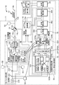
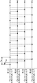
- FIG. 1 It is a functional block diagram which shows the structure of the distributed optical fiber sound wave detection apparatus which concerns on 1st this embodiment of this invention. It is a figure for demonstrating the optical pulse after the phase modulation output from the optical pulse emission part of the said distributed optical fiber acoustic wave detection apparatus. It is a figure for demonstrating the phase measurement part of the said distributed optical fiber acoustic wave detection apparatus. It is a figure which shows the circuit of the digital signal processing part of the said distributed optical fiber acoustic wave detection apparatus. (A) to (D) are conceptual diagrams for explaining a modulated optical pulse and a pulse compression restoration filter for demodulating the optical pulse.
- the distributed optical fiber acoustic wave detection device 10 uses an optical fiber (detection optical fiber) 12 as a sensor, and detects each acoustic wave colliding with each region in the longitudinal direction with high sensitivity and high accuracy. , High resolution in the longitudinal direction (hereinafter, also simply referred to as “longitudinal resolution”) is realized. Note that the distributed optical fiber acoustic wave detection device 10 according to the present embodiment includes not only the acoustic wave colliding with a specific position (part) in the longitudinal direction (z-axis direction) of the optical fiber for detection 12 but also each region in the longitudinal direction. It is also possible to detect the distribution of sound waves that have collided simultaneously.
- this distributed optical fiber acoustic wave detection device 10 sound can be recorded using the detection optical fiber 12 instead of the microphone. Further, for example, by detecting the sound wave (for example, a sound wave of about 1 kHz) propagating through the ground by inserting the detection optical fiber 12 into the oil well or the like, the state of the oil well or the inside of the ground is detected. Can be observed. Further, in the medical field, for example, by detecting a sound wave propagating inside the human body (for example, an ultrasonic wave having a frequency of 3 MHz to 30 MHz) with the detection optical fiber 12, it is possible to observe the inside of the human body. Become.
- the distributed optical fiber acoustic wave detection device 10 includes a device main body 11 and a detection optical fiber 12 as shown in FIG.
- the apparatus main body 11 includes an optical pulse emitting unit 20, a phase measuring unit 50, an optical circulator 14, a Rayleigh scattered light receiving unit 30, a control processing unit 16, and an output unit 40.
- an optical amplifier such as an erbium-doped optical fiber (EDFA) may be disposed between the optical pulse emitting unit 20 and the optical circulator 14.
- EDFA erbium-doped optical fiber
- an LN switch for securing an extinction ratio of the optical pulse output from the optical pulse emitting unit 20 is disposed between the optical pulse emitting unit 20 and the optical circulator 14. May be.
- the extinction ratio of the light pulse output from the light pulse emitting unit 20 is several tens dB or more.
- the detection optical fiber 12 is used as a sensor for detecting a sound wave that has collided with the optical fiber 12.
- the detection optical fiber 12 is a long optical fiber having a first end (one end) 12a and a second end 12b which is an end opposite to the first end 12a.
- the length dimension (full length) L of the detection optical fiber 12 is about 30 km when the distributed optical fiber sound wave detection device 10 is used for sound wave detection in the oil well.
- the distance is about 100 m.
- a light pulse (probe light) is incident on the optical fiber 12 from the first end portion 12a of the optical fiber for detection 12, and a Rayleigh generated in the optical fiber for detection 12 due to the optical pulse.
- Light related to the scattering phenomenon (Rayleigh backscattered light) is emitted to the outside.
- the optical pulse emitting unit 20 includes a light source unit 22 that outputs an optical pulse having a predetermined frequency, and a modulation unit 24 that modulates the optical pulse output from the light source unit 22 (phase modulation in this embodiment). Is made incident into the detection optical fiber 12 from the first end 12 a of the detection optical fiber 12.
- the light source unit 22 includes a light source 220, a first beam splitting unit 222, and a second beam splitting unit (spectral beam) 224, and outputs a first light pulse and a second light pulse.
- the light source 220 can output (emit) an optical pulse having a predetermined frequency. Specifically, as shown in FIG. 2, the light source 220 outputs optical pulses P 1 , P 2 , P 3 ,... P i having a predetermined pulse width D at a first time interval T D. , Generate pulsed light.
- the light source 220 outputs a linearly polarized light pulse P i (pulse light).
- the light source 220 is controlled by the control processing unit 16, and the oscillation wavelength (oscillation frequency) is changed by the temperature and driving current being changed by the control processing unit 16.
- the output interval of the light pulse P i is also controlled by the control processing unit 16.
- the light source 220 of this embodiment is a laser diode (LD).
- the pulse width D of the optical pulse P i is set based on the length L of the detection optical fiber 12. Specifically, energy of more light pulses P i pulse width D is larger increases. Therefore, when the Rayleigh scattered light receiving section 30 of the Rayleigh scattered light by the light pulse P i generated in the vicinity of the second end portion 12b which is incident from the first end portion 12a of the detection optical fiber 12 is received, the detection beam The pulse width is set such that the signal intensity (intensity of Rayleigh scattered light) necessary for detecting a sound wave that has collided near the second end 12b of the fiber 12 is sufficiently secured in the received Rayleigh scattered light. D is set. In general, the pulse width D increases as the length L of the detection optical fiber 12 increases.
- time interval T D between the optical pulse P i is set based on the frequency of the sound waves to be detected of the distributed optical fiber wave detecting apparatus 10. Details are as follows.
- the time interval T D between the optical pulses P i must be less than or equal to a half of one period of the sound wave to be detected. That is, the distribution of sound waves that can be detected (scanned) by one light pulse P i (the distribution of sound waves that collide with each region in the longitudinal direction) is the same as the sampling period of the light pulse P i in the detection optical fiber 12. It is within the range that can be reciprocated in time. Then, a high frequency wave has a short sampling period required for one cycle is short, thereby, the range of the light pulse P i can reciprocate the detection optical fiber 12 in the sampling period is short.
- the interval between the optical pulses P i is a sound wave to be detected (if the frequency band of the sound wave to be detected is wide, the highest frequency sound wave in the frequency band) time interval shorter than a half of one period of) (as a first time interval) T D, a plurality at predetermined intervals in the detection optical fiber 12 (interval corresponding to the first time interval T D) light pulses P 1, P 2, P 3 , to proceed ... P i.
- each of the longitudinal The Rayleigh scattered light from each region in the longitudinal direction can be received in order so that the Rayleigh scattered light from the regions do not overlap each other.
- the first time interval T D in this embodiment is a specific time interval in a sampling period defined by sound waves to be detected (the half period following the time of the sound wave).
- each optical pulse P i output at the first time interval T D is phase-modulated by different (independent) code sequences in the modulation unit 24, the received Rayleigh scattered light is demodulated. Accordingly, it is possible to determine the Rayleigh scattered light is caused by any light pulse P i.
- the distributed optical fiber acoustic wave detection device 10 uses the long detection optical fiber 12 as a sensor, and even when detecting a high-frequency acoustic wave (for example, one cycle such as an ultrasonic wave is short). By outputting the optical pulse P i at the time interval T D , the distribution of sound waves along the detection optical fiber 12 can be detected with high accuracy.
- a high-frequency acoustic wave for example, one cycle such as an ultrasonic wave is short.
- the first beam splitting unit 222 splits (branches) the light pulse P i output from the light source 220 while maintaining linearly polarized light, and the split light pulse P i is connected to the second beam splitting unit 224.
- the output is output to the Rayleigh scattered light receiving unit 30 (specifically, the digital coherent receiving unit 320).
- the second splitting unit 224 the light pulse P i from the first splitting unit 222, and split into a first optical pulse while maintaining the linearly polarized light the second optical pulse, these first optical pulse and the Two optical pulses (a pair of optical pulses) are output to the modulation unit 24.
- the second beam splitting unit 224 branches the input light pulse at a ratio of 1/2 (50:50) and outputs it.
- the second spectroscopic unit 224 of this embodiment is a 3 dB spectrometer (3 dB splitter).
- the modulation unit 24 includes a phase modulation unit 240 and a synthesis unit 242, and each of the first light pulse and the second light pulse output from the light source unit 22 (specifically, the second beam splitting unit 224). Phase modulation is performed, and the phase-modulated first optical pulse and the second optical pulse are combined.
- the phase modulator 240 includes a first phase modulator 240a that performs phase modulation of the first optical pulse, a second phase modulator 240b that performs phase modulation of the second optical pulse, and a first code sequence A i . a pair of code sequence and a second code sequence B i: having a code generator 244 for creating (pair code see FIG. 2), a.
- the first phase modulator 240 a performs phase modulation of the first optical pulse based on the first code sequence A i input from the code generation unit 244.
- the second phase modulator 240 b performs phase modulation of the second optical pulse based on the second code sequence B i input from the code generation unit 244.
- the code generation unit 244 generates a pair code including the first code sequence A i and the second code sequence B i and outputs the first code sequence A i to the first phase modulator 240a. and it outputs the second code sequence B i to the second phase modulator 240b with.
- the pair code (first code sequence A i and second code sequence B i ) generated by the code generation unit 244 has a predetermined length (predetermined sequence length) based on the length L of the detection optical fiber 12. ),
- the first and second optical pulses are respectively phase-modulated by the pair code, whereby each optical pulse is divided into a plurality of cells having a predetermined width d (FIG. 5A and FIG. 5). (See FIG. 5B). That is, each optical pulse is phase-modulated at the modulation speed d.
- the width d of each cell is set based on the longitudinal resolution of the detection optical fiber 12 in the detection of sound waves. Details are as follows.
- the optical pulse P i is divided into a plurality of cells by phase modulation using a predetermined code sequence
- each of these cells can perform the same function as an optical pulse having a small pulse width. Therefore, the width (cell width) d of each cell is set shorter than the target longitudinal resolution.
- each optical pulse by dividing each optical pulse into a plurality of cells having a width d in this way, it is possible to detect a sound wave having a high frequency.
- measurement in order to detect a high-frequency sound wave, when a single pulse is used, measurement must be performed using an optical pulse with a pulse width shorter than the distance traveled by this high-frequency sound wave in one cycle.
- each cell when an optical pulse is divided into a plurality of cells having a width d, each cell can function in the same manner as an optical pulse having a small pulse width as described above, and therefore can be detected by an optical pulse having a pulse width d. It is possible to detect sound waves having a high frequency (high frequency corresponding to the width d of each cell).
- the first and second optical pulses are each phase-modulated by a code sequence (pair code) that forms a cell having a width d set in this way.
- the code generation unit 244 of this embodiment outputs a Golay code sequence.
- the code sequence output by the code generation unit 244 is not limited to the Golay code sequence. That is, the code sequence output from the code generation unit may be a pair code in which the sum of the autocorrelation functions is a ⁇ function, or a code in which the autocorrelation function is independently a ⁇ function. May be a code sequence.
- the code generation unit 244 is different for each light pulse P i outputted from the light source unit 22 (independent) for generating a pair code. As a result, it is possible to determine which optical pulse P i causes the Rayleigh scattered light returned from the detection optical fiber 12.
- Synthesis unit 242 respectively and outputs the combining the first light pulse and the second optical pulse phase-modulated in one of the light pulses P i in the phase modulating section 240.
- the combining unit 242 of the present embodiment has a pair of input terminals (a first input terminal 242a and a second input terminal 242b), and the pair of input terminals 242a and 242b are polarizations (polarized waves) of input light.
- the directions are specified so as to be orthogonal to each other. That is, the combining unit 242 of the present embodiment combines and outputs the first optical pulse and the second optical pulse with the polarization directions orthogonal to each other.
- the first optical pulse input to the first input terminal 242a is also referred to as a P polarization pulse
- the second optical pulse input to the second input terminal 242b is also referred to as an S polarization pulse.
- the optical path connecting the components from the light source 220 to the combining unit 242 is configured by a polarization maintaining optical fiber (PM fiber) or a waveguide that maintains the polarization state.
- PM fiber polarization maintaining optical fiber
- the light pulse P i output as linearly polarized light from the light source 220 maintains its polarization state even after the spectrum in the second beam splitting unit 224.
- a polarization maintaining optical fiber or the like that connects the second spectroscopic unit 224 and the first input terminal 242a, and a polarization maintaining optical fiber or the like that connects the second spectroscopic unit 224 and the second input terminal 242b are By connecting to the input terminals 242a and 242b of the combining unit 242 so that the polarization directions are orthogonal to each other, the pair of optical pulses (first and second optical pulses) input to the combining unit 242 have the polarization direction. The state is orthogonal to each other.
- Phase measurement unit 50 the phase of the optical pulses P i which the light source 220, and outputs the measurement to detect a change in phase (time variation of phase) due to the light source 220 in the optical pulse.
- the phase measurement unit 50 is connected to an optical fiber (waveguide) extending from the light source 220 and the demodulation unit 324, and outputs a phase signal corresponding to the measurement result to the demodulation unit 324.
- the demodulator 324 performs correction based on the phase signal, the influence of the phase change caused by the light source 220 can be removed from the demodulated signal.
- the phase measurement unit 50 includes an I / Q separation unit 52 and a phase change deriving unit 54 as shown in FIG.
- the I / Q separation unit 52 includes two light guide paths 521 and 522 branched from an optical fiber (waveguide) extending from the light source 220, an optical coupler 523, and a 90 ° phase shifter 524, and outputs from the light source 220. I / Q separation is performed on the light (light pulse).
- the light guide paths 521 and 522 branch a part of the light traveling in the optical fiber (waveguide) extending from the light source 220 and guide it to the optical coupler 523. These light guide paths 521 and 522 have different optical path lengths. Specifically, the optical path length E 2 light guide path 521 is also tau than the optical path length E 1 of the light guide path 522 (specifically, the distance which the light pulse proceeds during the time tau) longer by.
- the optical coupler 523 causes the light guided by the light guide paths 521 and 522 to interfere with each other and output the light. At this time, since the optical path lengths of the light guide path 521 and the light guide path 522 are different from each other, the light guided by the light guide path 521 reaches the optical coupler 523 later than the light guided by the light guide path 522. .
- the optical coupler 523 branches the light after the interference into two and outputs it to the phase change deriving unit 54.
- the 90 ° phase shifter 524 shifts one phase of the light branched by the optical coupler 523 by 90 °.
- I and Q signals are output from the I / Q separator 52 as described above.
- the phase change deriving unit 54 performs A / D conversion on the I and Q signals from the I / Q separation unit 52 and synthesizes them to obtain the phase ⁇ (t) of the light output from the light source 220. Specifically, the phase change deriving unit 54 obtains the phase ⁇ (t) of the light by the following equation (2).
- phase change deriving unit 54 may obtain the rate of change of the phase at each time by differentiating the phase ⁇ (t) obtained by the above equation (2) with respect to time (d ⁇ (t) / dt). it can.
- the phase change deriving unit 54 outputs the phase change of the light output from the light source 220 (phase change caused by the light source 220 in the light pulse) ⁇ (t) obtained as described above as a phase signal.
- phase measurement unit 50 The specific configuration of the phase measurement unit 50 is not limited to the above configuration. That is, the phase measurement section 50 may be other configurations if it is possible to detect a change in phase due to the light source 220 in the light pulse P i.
- the optical fibers and waveguides constituting the respective optical paths (light guides 521, 522, etc.) from the optical fiber extending from the light source 220 to the phase change deriving unit 54 also have polarization maintaining characteristics. Have. That is, the polarization direction of the light branched from the optical fiber or the like extending from the light source 220 is maintained up to the phase change deriving unit 54.
- the optical circulator 14 is an irreversible optical component in which incident light and outgoing light have a cyclic relationship with their terminal numbers. That is, the light incident on the first terminal 14a is emitted from the second terminal 14b and is not emitted from the third terminal 14c. The light incident on the second terminal 14b is emitted from the third terminal 14c and is not emitted from the first terminal 14a. The light incident on the third terminal 14c is emitted from the first terminal 14a and is not emitted from the second terminal 14b.
- the first terminal 14a of the optical circulator 14 is connected to the optical pulse emitting unit 20, the second terminal 14b is connected to the first end 12a of the detection optical fiber 12, and the third terminal 14c is Rayleigh scattered light. Connected to the receiver 30.
- Rayleigh scattered light receiving section 30 includes a phase change obtaining unit 32 includes a sound wave detector 34, a detection by the incidence of P i optical pulses (optical pulse P-polarized light pulses and the S-polarized light pulse is synthesized) Rayleigh scattered light generated in the optical fiber 12 is received.
- P i optical pulses optical pulse P-polarized light pulses and the S-polarized light pulse is synthesized
- the phase change derivation unit 32 includes a digital coherent reception unit (separation / detection unit) 320, a digital signal processing unit 322, a demodulation unit 324, and a derivation unit 36, and performs phase modulation in the optical pulse emission unit 20.
- the phase change is obtained from the Rayleigh scattered light subjected to the corresponding demodulation.
- the digital coherent receiving unit 320 is connected to the detection optical fiber 12 (specifically, the third terminal 14c of the optical circulator 14) and the light source unit 22 (specifically, the first spectroscopic unit 224).
- the detection optical fiber 12 specifically, the third terminal 14c of the optical circulator 14
- the light source unit 22 specifically, the first spectroscopic unit 224.
- P / S polarization in the present embodiment orthogonal polarization components
- I / Q channel orthogonal phase components
- the digital coherent receiving unit 320 includes a polarization beam splitter 320a, a branching device 320b, a first optical 90 ° hybrid 321a, and a second optical 90 ° hybrid 321b.
- the polarization separator 320a converts the Rayleigh scattered light received by the Rayleigh scattered light receiving unit 30 from the detection optical fiber 12 into first Rayleigh scattered light (hereinafter simply referred to as “P polarized scattered light”) having a predetermined polarization direction. ) And second Rayleigh scattered light having a polarization direction orthogonal to the first Rayleigh scattered light (hereinafter also simply referred to as “S polarized scattered light”).
- the branching device 320b branches the light pulse P i from the first beam splitting unit 222 into two (light pulses P i1 and P i2 ).
- the first optical 90 ° hybrid 321a causes the optical pulse P i1 divided by the branching device 320b as local light (local oscillation light) to interfere with P-polarized scattered light from the polarization separator 320a and It is separated into Q components, which are converted into I and Q signals (analog signals) and output.
- the second optical 90 ° hybrid 321b makes the optical pulse P i2 divided by the branching device 320b as local light (local oscillation light) and interferes with the S-polarized scattered light from the polarization separator 320a, thereby reducing the I component. It is separated into Q components, which are converted into I and Q signals (analog signals) and output.
- optical pulse emitting unit 20 uses this matrix to output an optical pulse (first signal after phase modulation) output from the optical pulse emitting unit 20.
- a DP-QPSK (Dual Polarization Quadrature Phase Shift Keying) receiving module is used as the digital coherent receiving unit 320 and the digital signal processing unit 322.
- the distributed optical fiber acoustic wave detection device 10 of the present embodiment high-speed optical transmission of 40 Gbit / s or more is performed, so the A / D conversion resolution in the digital signal processing unit 322 is only 6 bits.
- the optical pulse P i is divided by phase modulation using the Golay code sequence to form 2 12 cells, and when this is demodulated, it is converted into one optical pulse P i .
- each cell of the Rayleigh scattered light includes (has) the distortion information of the site where the Rayleigh scattered light of the detection optical fiber 12 is generated, the accuracy can be obtained by collecting these information by demodulation. .
- the resolution of A / D conversion in the digital signal processing unit 322 is low, by performing pulse compression using a code sequence as in the distributed optical fiber acoustic wave detection device 10, high-accuracy acoustic waves can be obtained. Detection is realized.
- the demodulation unit 324 performs correction based on the phase signal from the phase measurement unit 50 on the P-polarized digital signal and the S-polarized digital signal that have been polarization-separated by the digital coherent receiving unit 320 and the digital signal processing unit 322, respectively. After performing, the demodulation corresponding to the phase modulation in the modulation unit 24 is performed.
- the demodulator 324 includes a first demodulator 324a and a second demodulator 324b.
- the first demodulator 324a and the second demodulator 324b are connected to the code generator 244.
- the first demodulating unit 324 a performs correction based on the phase signal from the phase measuring unit 50 on the P-polarized digital signal output from the digital signal processing unit 322.
- the phase signal is a signal obtained by measuring the change in phase caused by the light source in the light pulse P i that corresponds to P polarized digital signal to be corrected.
- a P-polarized digital signal (a digital signal corresponding to P-polarized scattered light generated in the detection optical fiber 12 by the first optical pulse phase-modulated by the first code sequence A i ) is represented by A i.
- the first demodulator 324a performs the correction shown in the following equation (3).
- the first demodulating unit 324a substitutes ⁇ (t) obtained by the phase measuring unit 50 for “ ⁇ (t)” of ⁇ i ⁇ (t) shown on the right shoulder of e in Expression (3).
- the P-polarized digital signal is corrected.
- the influence of the phase change resulting from the light source 220 is removed from the P-polarized digital signal.
- the second demodulator 324b applies the phase signal from the phase measuring unit 50 (P-polarized wave in the first demodulator 324a) to the S-polarized digital signal B i ′ output from the digital signal processor 322. Correction based on the phase signal used for correcting the digital signal (correction shown in the following equation (4)) is performed.
- the first demodulator 324a demodulates the corrected P-polarized digital signal based on the code (first code sequence A i ) when the first optical pulse is phase-modulated by the modulator 24. I do.
- the second demodulator 324b demodulates the corrected S-polarized digital signal based on the code (second code sequence B i ) obtained when the second optical pulse is phase-modulated by the modulator 24. I do.
- the reference numerals 1 and -1 correspond to 0 and ⁇ of phase modulation.
- the P-polarized digital signal corresponding to the first optical pulse is demodulated by the code (pulse compression restoration matched filter) A 1 * corresponding to the first code sequence A 1 . Done. Specifically, the first demodulator 324a demodulates by the calculation of A 1 ′ ⁇ A 1 * . Further, in the second demodulator 324b, the P-polarized digital signal corresponding to the second optical pulse is demodulated by a code (pulse compression restoration matched filter) B 1 * corresponding to the second code sequence B 1. . Specifically, the second demodulation unit 324b demodulates the signal by calculating B 1 ′ ⁇ B 1 * .
- a 1 * and B 1 * are obtained by reversing the arrangement of signs of A 1 and B 1 ,
- a 1 * ( ⁇ 1,1, ⁇ 1, ⁇ 1, ⁇ 1,1,1,1,1,1, ⁇ 1,1,1,1,1)
- B 1 * (1, ⁇ 1,1,1,1,1, ⁇ 1, ⁇ 1, ⁇ 1,1,1, ⁇ 1,1,1,1,1) (See FIG. 5C and FIG. 5D).
- the deriving unit 36 includes a pair combining unit 360, a phase deriving unit 362, and a phase change deriving unit 364, and obtains the phase change ⁇ of the demodulated Rayleigh scattered light.
- the pair combining unit 360 obtains a demodulated signal by summing (combining) the P-polarized scattered light and the S-polarized scattered light demodulated by the demodulating unit 324, respectively. Specifically, the pair combining unit 360 demodulates the P-polarized digital signal (I and Q signals: signals corresponding to P-polarized scattered light) demodulated by the first demodulating unit 324a and the second demodulating unit 324b.
- the S-polarized digital signal (I and Q signals: signals corresponding to S-polarized scattered light) is synthesized.
- the combination of the P-polarized digital signal demodulated in the first demodulator 324a and the P-polarized digital signal demodulated in the second demodulator 324b is combined with the I of each signal.
- the demodulated signal (I, Q signal) is generated by taking the sum of the components (signals) and the sum of the Q components (signals).
- Wave scattered light returns to one light pulse (single pulse).
- Rayleigh scattered light (the P polarized scattered light and the S polarized light in the detection optical fiber 12) possessed by each cell (each cell of the P polarized scattered light and each cell of the S polarized scattered light).
- the distortion information of the part where the wave scattering light) is generated is collected into a single pulse having a pulse width corresponding to one cell (light pulse not divided into a plurality of cells).
- the distributed optical fiber acoustic wave detection apparatus 10 of the present embodiment demodulates the Rayleigh scattering light generated in the detection optical fiber 12 by the optical pulse P i (i.e., a pulse compression using a predetermined code sequence
- the optical pulse P i i.e., a pulse compression using a predetermined code sequence
- the phase deriving unit 362 obtains the phase ⁇ of the Rayleigh scattered light received by the Rayleigh scattered light receiving unit 30 from the demodulated signal obtained by the pair combining unit 360. Specifically, the phase deriving unit 362 obtains the phase ⁇ of the Rayleigh scattered light from the demodulated signals (I and Q signals) obtained by the pair combining unit 360 according to the following equation (5).
- the phase deriving unit 362 outputs the phase ⁇ of the Rayleigh scattered light thus obtained to the phase change deriving unit 364 and stores it in the storage unit 16 a of the control processing unit 16.
- the phase change deriving unit 364 obtains a difference (phase change) ⁇ between the phase of the Rayleigh scattered light most recently obtained by the phase deriving unit 362 and the phase of the Rayleigh scattered light obtained last time. For example, when sound waves are detected at the times t 1 , t 2 , t 3 ,... T i by the distributed optical fiber acoustic wave detection device 10, the phase change deriving unit 364 determines the Rayleigh obtained at the time t i. and phase [Phi i of the scattered light, Rayleigh scattered light obtained at time t i-1 the difference between the phase [Phi i-1 obtained as a phase change .DELTA..PHI.
- each t i Data of the phase change ⁇ at each position in the z-axis direction (longitudinal direction of the detection optical fiber 12) (distribution data of the phase change ⁇ along the z-axis) is created, and the distribution data of this phase change ⁇ Is stored in the storage unit 16a.
- the sound wave detection unit 34 depends on the time from when the light pulse P i is output from the light pulse emitting unit 20 until the Rayleigh scattered light generated by the light pulse P i is received by the Rayleigh scattered light receiving unit 30.
- the position in the longitudinal direction where the Rayleigh scattered light in which the phase change ⁇ has occurred is specified.
- the magnitude of the phase change ⁇ of Rayleigh scattered light at each position in the longitudinal direction represents a sound wave that has collided with the position of the detection optical fiber 12 from the outside.
- the control processing unit 16 is a part for controlling each component of the distributed optical fiber acoustic wave detection device 10, and includes, for example, a storage unit 16a such as a microprocessor, a working memory, and a memory for storing necessary data. ing.
- control processing unit 16 performs arithmetic processing of various data (such as the distribution of phase change ⁇ ) obtained by the sound wave detection unit 34 and stored in the storage unit 16a, and the sound wave that has collided with the detection optical fiber 12 is processed.
- various data such as the distribution of phase change ⁇
- the control processing unit 16 can specify the position of the sound wave transmission source from the distribution of the phase change ⁇ along the longitudinal direction.
- the control processing unit 16 determines the position of the sound wave source along with the passage of time (t 1 , t 2 , t 3 ,..., T i ) from the time change of the distribution of the phase change ⁇ along the longitudinal direction. Movement and the like can also be detected.
- the output unit 40 includes a display unit 42 and a speaker unit 44, and externally outputs various types of sound wave information detected by the sound wave detection unit 34 at each position in the longitudinal direction based on the distribution of the phase change ⁇ stored in the storage unit 16 a. Output. Specifically, the output unit 40 uses the display unit 42 to display, for example, an axis indicating the distance in the longitudinal direction of the detection optical fiber 12 (z axis), an axis indicating the elapsed time, and an axis indicating the intensity of the detected sound wave. A graph having three axes, a position of a sound wave transmission source obtained by the control processing unit 16, and the like are displayed. The output unit 40 outputs (reproduces) the sound wave detected by the speaker unit 44 at an arbitrary position in the longitudinal direction of the detection optical fiber 12.
- the output unit 40 sets a reproduction window at a predetermined position on the z-axis in the distribution data of the phase change ⁇ stored in the storage unit 16a (see FIG. 6), and the reproduction window contains the reproduction window.
- a change with the passage of time (t 1 , t 2 , t 3 ,..., T i ) of the phase change ⁇ is reproduced as a change in sound ( ⁇ voltage).
- the reproduction window is usually a straight line connecting specific positions on the z-axis (longitudinal direction of the detection optical fiber 12) at each time t 1 , t 2 , t 3 ,... Set above.
- the playback window is not limited to the one set on the straight line, and, for example, a playback window having a predetermined width in the z-axis direction (a playback window shown on the left side of the single-point playback window in FIG. 6) is set. May be. In this case, each of the times t 1 , t 2 , t 3 ,.
- the detection optical fiber 12 is arranged.
- the detection optical fiber 12 may be installed in the air, or may be disposed in a wall such as the ground or a building, or on the surface of a vehicle such as an airplane or a structure such as a wall. Further, the detection optical fiber 12 may be arranged so as to be wound around a human body.
- the detection optical fiber 12 When installed in the air, it is possible to detect a sound wave that has propagated through the air and reached the detection optical fiber 12.
- it when it is placed in the wall of a ground or a building, or on the surface of a vehicle or structure, it propagates through each member constituting the ground, the wall, the vehicle, or the structure and reaches the detection optical fiber 12.
- the detected sound wave can be detected.
- an optical fiber already provided for communication in a building may be used as the detection optical fiber 12.
- the sound wave (sound) generated in the room propagates through the air, walls, etc. in the room in order and reaches the detection optical fiber (an optical fiber already provided for communication) 12.
- a sound wave for example, an ultrasonic wave
- the control processor 16 from the optical pulse emitting unit 20, and outputs the phase-modulated optical pulse P i in a first time interval T D, through the optical circulator 14 An input is made into the detection optical fiber 12. Details are as follows.
- the light source unit 22 outputs light pulses P i of and has a predetermined pulse width D linearly polarized light (step S1).
- the optical pulse P i the sound to be detected (when a predetermined frequency band, most frequency high sound) is output one after another in a first time interval T D that is set based on the period of.
- the optical pulse P i is split into a pair of optical pulses (first optical pulse and second optical pulse) by the second spectroscopic unit 224 and supplied to the modulation unit 24.
- each of the phase modulators 240a and 240b uses a pair code (first code sequence A i and second code sequence B i ) generated by the code generation unit 244 to use a pair of corresponding lights.
- Phase modulation is performed on each pulse (a pair of optical pulses dispersed in the second beam splitting unit 224) (step S2). That is, the first phase modulator 240a uses the first code sequence A i to phase modulate the first optical pulse, and the second phase modulator 240b uses the second code sequence B i to Phase modulation of the light pulse.
- each optical pulse is divided into a plurality of cells.
- the optical pulse P i is input into the detection optical fiber 12 from the first end 12 a via the optical circulator 14.
- a plurality of light pulses P 1 to the detection optical fiber 12, P 2, P 3, ..., P i proceeds at intervals corresponding to the first time interval T D toward the second end portion 12b ( (See FIG. 2).
- the sampling period is, for example, 25 ⁇ s (the sampling period may be equal to or less than this value).
- the distance traveled by the optical pulse P i in the optical fiber during this sampling period is 5 km. Therefore, the first time interval T D is set to 25 .mu.s (if this value or less may.).
- the optical pulse of the optical fiber 12 4 pulses (four) first A round trip is made at a time interval T D (25 ⁇ s interval or 5 km interval).
- the frequency of the sound wave to be detected is 10 MHz
- the sampling frequency is, for example, 50 ns (the sampling period may be equal to or less than this value).
- the distance traveled by the optical pulse P i in the optical fiber during this sampling period is 10 m. Therefore, the first time interval T D is set to 50 ns (if this value or less may.).
- the optical fiber 12 is a light pulse of 20 pulse (20) a first Reciprocate at time interval T D (50 ns interval or 10 m interval).
- the control processing unit 16 when the optical pulse P i is input into the detection optical fiber 12, the control processing unit 16 then collides with the detection optical fiber 12 from the Rayleigh scattered light received by the Rayleigh scattered light receiving unit 30. The detected sound wave is detected. Details are as follows.
- the optical fiber 12 When the sound wave reaches (collises) the detection optical fiber 12, the optical fiber 12 is distorted by the collision of the sound wave. This distortion is the distortion in the longitudinal direction of the detection optical fiber 12 (the central axis (tangent) direction of the detection optical fiber 12 at the position where the sound wave collides).
- the phase of the Rayleigh scattered light is changed compared to the Rayleigh scattered light generated at the same position when the distortion is not generated.
- the magnitude of the phase change ⁇ corresponds to the magnitude and frequency of the sound wave that has collided with the detection optical fiber 12.
- the Rayleigh scattered light receiving unit 30 changes the phase of the Rayleigh scattered light caused by the collision of the sound wave with the detection optical fiber 12 from the Rayleigh scattered light returned to the first end 12 a of the detection optical fiber 12.
- ⁇ disortion information
- a sound wave colliding with the detection optical fiber 12 is detected from the phase change ⁇ .
- it receives the Rayleigh scattered light generated by the light pulse P i that is incident on the detection optical fiber 12, from the Rayleigh scattered light, acquires information of the strain generated in the detection optical fiber 12 by the collision of the sound wave.
- the digital coherent receiving unit 320 separates the orthogonal polarization component (P / S polarization) and the orthogonal phase component (I / Q channel) of the received Rayleigh scattered light. .
- the digital signal processing unit 322 performs a P-polarized digital signal corresponding to the first optical pulse and an S-polarized digital corresponding to the second optical pulse by the circuit shown in FIG. A signal is generated and output.
- the first demodulator 324a (second demodulator 324b) performs phase modulation on the P-polarized digital signal (S-polarized digital signal) by the first phase modulator 240a (second phase modulator 240b). Corresponding demodulation (A i ′ ⁇ A i * and B i ′ ⁇ B i * ) is performed (step S4).
- the pair combiner 360 transmits the P-polarized scattered light (signal corresponding to the P-polarized scattered light) and the S-polarized light obtained by this demodulation.
- the sum of the wave scattered light (the signal corresponding to the S polarized light scattered) is taken as a demodulated signal.
- a signal corresponding to Rayleigh scattered light (light pulse) divided into a plurality of cells by phase modulation corresponds to a single pulse (light pulse not divided into a plurality of cells) having a pulse width of one cell. Signal.
- each cell includes distortion information of the reflected position. Therefore, the distortion information contained in each cell is collected by becoming a single pulse (a signal corresponding to a single pulse) by demodulation. Thereby, distortion information equivalent to the amount of information obtained when the same number of light pulses as the number of cells is output to the detection optical fiber 12 from a signal corresponding to one light pulse (Rayleigh scattered light) is obtained. It becomes possible.
- the phase deriving unit 362 uses the demodulated signal and Rayleigh scattered light corresponding to the demodulated signal. Find the phase of. Then, the phase change deriving unit 364 determines the phase change of the Rayleigh scattered light from the phase of the Rayleigh scattered light and the phase of the Rayleigh scattered light previously obtained by the phase deriving unit 362 (that is, the detection light by the collision of sound waves). A phase change of Rayleigh scattered light due to distortion generated in the fiber 12) ⁇ is obtained (step S5).
- the derivation unit 36 uses the Rayleigh scattered light at the time of the previous measurement (for example, time t 1 in FIG. 6), The phase change ⁇ is obtained from the phase difference with the Rayleigh scattered light at the next measurement (for example, time t 2 in FIG. 6).
- phase change .DELTA..PHI wave detector 34, form respective times t 1, t 2, t 3 , ..., the distribution data of the phase change .DELTA..PHI in the z-axis direction of each t i (longitudinal direction), respectively And it stores in the memory
- the distribution of the phase change ⁇ in the z-axis direction (longitudinal direction) is the distribution of sound waves that have collided with each position in the z-axis direction.
- sampling of one detected by the light pulse P i can be z-axis direction distribution of a sound wave (longitudinal direction), the light pulse P i is wave detection optical fiber 12 (wave to be detected) It is within the range that can reciprocate in the period, that is, the time of half the period of the maximum frequency of the sound wave to be detected.
- a plurality of light pulses P 1, P 2, P 3 , ..., P i by the output from the optical pulse emitting unit 20 in the first time interval T D, the plurality of light pulses P 1, P 2, P 3, ..., it can be by P i, to scan the entire region of the z-axis direction of the detection optical fiber 12 (the longitudinal direction) in the sampling period.
- the output unit 40 When the distribution of the phase change ⁇ in the z-axis direction (longitudinal direction) (distribution of the sound wave in the z-axis direction) is detected as described above, the output unit 40 then moves to a specific position in the z-axis direction (longitudinal direction).
- the change of the phase change ⁇ with the passage of time (t 1 , t 2 , t 3 ,..., T i ) at is converted into a change in voltage.
- the sound wave colliding with the specific position of the detection optical fiber 12 is reproduced (step S7).
- control processing unit 16 specifies the position of the sound wave transmission source from the distribution of the phase change ⁇ in the z-axis direction (longitudinal direction) stored in the storage unit 16a by the sound wave detection unit 34, and the output unit 40 displays the display unit 40 This is indicated by 42.
- a program for reproducing the state of the ground or the inside of the structure from the distribution of the phase change ⁇ in the z-axis direction can be incorporated into the control processing unit 16.
- the control processing unit 16 executes the program and thereby obtains the phase change in the z-axis direction (longitudinal direction). From the distribution of ⁇ , the underground state, the state of the oil well, and the state inside the structure can be reproduced, and the output unit 40 can display these various types of information.
- the control processing unit 16 When a program for reproducing the internal state of the human body from the distribution of the phase change ⁇ in the z-axis direction (longitudinal direction) is incorporated in the control processing unit 16, the sound wave propagated through the human body is detected by the detection optical fiber 12.
- the control processing unit 16 detects the internal state of the human body from the obtained distribution of the phase change ⁇ in the z-axis direction (longitudinal direction), and the output unit 40 detects this. Can be displayed as an image.
- the optical pulse P i phase-modulated by a predetermined code sequence is made incident on the detection optical fiber 12, and the detection optical fiber is detected by the optical pulse P i .
- demodulation corresponding to the phase modulation on the Rayleigh scattered light generated in 12 that is, performing pulse compression using a predetermined code sequence
- a small pulse width pulse width corresponding to the cell width d
- an effect equivalent to that obtained by detecting a sound wave using an optical pulse having a strong signal intensity can be obtained.
- Golay code sequence code sequence of a predetermined length (length dimension length based on the L of the detection optical fiber 12) by phase-modulating the light pulse P i using In the optical pulse P i incident on the detection optical fiber 12, sufficient energy can be secured to detect the sound wave. Details are as follows.
- the pulse width D of the light pulses P i which is phase modulated by a long code sequence is greater according to the length of the code sequence, therefore, has a large energy as the light pulse P i that is phase modulated by a long code sequence. Therefore, when the Rayleigh scattered light generated in the vicinity of the second end 12b in the detection optical fiber 12 is received, the light is phase-modulated by a code sequence having a length sufficient to ensure the signal intensity necessary for detecting the sound wave. a pulse P i for the detection of acoustic waves. Thereby, even if Rayleigh scattered light generated at any position in the longitudinal direction of the long detection optical fiber 12 is received, the Rayleigh scattered light has sufficient signal intensity necessary for detection of sound waves. . For this reason, the sound wave which collided with each area
- each cell of the Rayleigh scattered light is Each includes (has) the distortion information of the site where the Rayleigh scattering occurs.
- many of the distortion information measured by one optical pulse P i is obtained. That is, since the distortion information contained in each cell is aggregated by demodulating the received Rayleigh scattered light, the distortion of the site where the Rayleigh scattering has occurred using a large number (corresponding to the number of cells) of light pulses. It is possible to obtain distortion information of the same level as that measured.
- the Rayleigh scattering light generated by a single light pulse P i a sufficient amount at the site of the detection optical fiber 12 resulting in the Rayleigh scattered light Distortion information is obtained.
- a distortion that occurs in the detection optical fiber 12 due to collision of sound waves and changes in a very short time can be detected with high accuracy.
- the optical pulse P i is divided into a plurality of cells having a predetermined width d by phase modulation, thereby obtaining the same longitudinal resolution as when measured using an optical pulse having the same pulse width as the width d of the cell. It is also possible. That is, by dividing the optical pulse P i to the number of cells corresponding to a predetermined length of the code sequence described above, of the light pulse P i detection optical fiber 12 with an energy sufficiently secured with the first It is possible to realize a high longitudinal resolution according to the cell width while enabling detection of a sound wave that has collided with a position distant from the one end 12a.
- a sufficient amount of distortion information is obtained at a site where Rayleigh scattered light is generated in the detection optical fiber 12 by one optical pulse P i .
- the digital coherent receiving unit 320 and the digital signal processing unit 322 when obtaining a phase change from a pair of Rayleigh scattered light (P-polarized scattered light and S-polarized scattered light) separated and demodulated by the demodulator 324, the influence of Rayleigh scattered light other than the pair of Rayleigh scattered light Can be eliminated. Thereby, highly sensitive and highly accurate detection of a sound wave can be performed more reliably.
- a pair of code sequences for example, Golay code sequences
- the sum of the autocorrelation functions of one of the pair of Rayleigh scattered light (for example, P-polarized scattered light) and the other Rayleigh scattered light becomes 0, so Rayleigh scattered light other than the pair of Rayleigh scattered light. Can be excluded from the measurement results.
- the distributed optical fiber acoustic wave detection apparatus 10 of this embodiment detects the phase changes due to the light source 220 in the light pulse P i by the phase measurement unit 50, demodulation corresponding to the phase modulation in the modulator 24 demodulates Before being performed in the unit 324, the received Rayleigh scattered light is corrected based on the measurement result by the phase measuring unit 50. Thereby, the influence of the phase change resulting from the light source 220 in the Rayleigh scattered light after demodulation can be suppressed. As a result, the distributed optical fiber acoustic wave detection device 10 of the present embodiment can accurately detect acoustic waves. Specifically, it is as follows.
- the phase of the output light beam changes with the passage of time, and this phase change has no regularity. Therefore, when the light source 220 whose phase changes is used in the distributed optical fiber acoustic wave detection device 10, if the received Rayleigh scattered light is demodulated as it is, the post-demodulation Rayleigh scattered light is influenced by the phase change caused by the light source 220. (Phase noise) is included.
- the phase change due to the light source 220 of the light pulse P i is measured, a correction based on the measurement result to the Rayleigh scattering light before demodulation By doing so, the phase noise is removed, and the influence of the phase noise in the Rayleigh scattered light after demodulation is suppressed. This makes it possible to detect sound waves with high accuracy even when using the light source 220 in which the phase of the output light beam changes with the passage of time.
- the distributed optical fiber acoustic wave detection device 10A includes a device main body 11 and a detection optical fiber 12.
- the apparatus main body 11 includes an optical pulse emitting unit 20A, phase measuring units 50A and 50B, an optical circulator 14, a Rayleigh scattered light receiving unit 30A, a control processing unit 16, and an output unit 40.
- an optical amplifier such as an erbium-doped optical fiber (EDFA) is disposed between the optical pulse emitting unit 20A and the optical circulator 14 as in the first embodiment. May be.
- EDFA erbium-doped optical fiber
- Optical pulse emitting unit 20A includes a light source section 22A that outputs an optical pulse of a predetermined frequency, a modulation unit 24A for phase modulating the optical pulse P i to the output of the light source unit 22A, an intensity modulator 26, a light A pulse is caused to enter the detection optical fiber 12 from the first end 12 a of the detection optical fiber 12.
- the light source unit 22A includes a first light source 220A, a second light source 220B, a third beam splitting unit 225, and a fourth beam splitting unit 226.
- the first light source 220A outputs a first optical pulse of a particular wavelength lambda 1.
- the second light source 220B outputs a second light pulse having a wavelength ⁇ 2 different from the wavelength ⁇ 1 . That is, the first optical pulse and the second optical pulse have different wavelengths ⁇ .
- the third beam splitting unit 225 splits (branches) the first light pulse output from the first light source 220A, and the split first light pulse is modulated by the modulation unit 24A and the Rayleigh scattered light receiving unit 30A (in detail, The signal is output to the first mixer 312a) of the separation / detection unit 312.
- the fourth beam splitting unit 226 splits (branches) the second light pulse output from the second light source 220B, and modulates the split second light pulse with the modulating unit 24A and the Rayleigh scattered light receiving unit 30A (in detail, The signal is output to the second mixer 312b) of the separation / detection unit 312.
- the modulation unit 24A includes a phase modulation unit 240A and a synthesis unit 242A.
- the first light pulse and the second light output from the light source unit 22A (specifically, the first light source 220A and the second light source 220B). Each pulse is phase-modulated and synthesized.
- the phase modulation unit 240A includes a pair of code sequences (a pair code: FIG. 2) including a first phase modulator 240a, a second phase modulator 240b, and a first code sequence A i and a second code sequence B i . And a pulse generator 28 for generating a reference).
- a pair code FIG. 2
- the phase modulation unit 240A includes a pair of code sequences (a pair code: FIG. 2) including a first phase modulator 240a, a second phase modulator 240b, and a first code sequence A i and a second code sequence B i .
- a pulse generator 28 for generating a reference).
- Pulse generator 28 a first optical pulse and the second and the code generating unit 244 that generates a pair codes used in the phase modulation of the light pulses, the light pulse P i signal for intensity modulation of the synthesized (intensity signal ) To generate an intensity modulation signal generation unit 245.
- Intensity modulation signal generator 245 is connected to the intensity modulator 26, a pulse width D and a pulse interval corresponding to the pair code generated in the code generation unit 244 (first time interval) T D, for the intensity modulation A signal is output (see FIG. 2).
- Combining unit 242A and outputs the combining the first light pulse and second optical pulses, respectively, in the phase modulating section 240A has been phase-modulated in one of the light pulse P i.
- Combining unit 242A of the present embodiment wavelength division multiplexing: by (WDM Wavelength Division Multiplex) technology, combined to output to the first one of the light pulses and second light pulses light pulses P i.
- Intensity modulation section 26, based on the intensity modulation signal from the intensity modulation signal generator 245 of the pulse generator 28, modulates the intensity of the light pulses P i which is output from the combining unit 242A.
- the light pulse P i of and the pulse width D is divided width into a plurality of cells of d is output at the first time interval T D.
- the phase measurement unit (first phase measurement unit) 50A measures the phase of the first light pulse output from the first light source 220A, and the phase change caused by the first light source 220A in the first light pulse. (Time change in phase) is detected, and a phase signal corresponding to the measurement result is output to the first demodulator 324a.
- the phase measurement unit (second phase measurement unit) 50B measures the phase of the second light pulse output from the second light source 220B, and the phase change caused by the second light source 220B in the second light pulse. (Time change in phase) is detected, and a phase signal corresponding to the measurement result is output to the second demodulator 324b.
- the Rayleigh scattered light receiving unit 30A includes a phase change deriving unit 32A and a sound wave detecting unit 34, and an optical pulse (an optical pulse obtained by combining a first optical pulse and a second optical pulse having different wavelengths from each other). ) receives the Rayleigh scattered light generated in the detection optical fiber 12 by the incidence of P i.
- the phase change deriving unit 32A includes a spectroscopic unit 310, a separation / detection unit 312, a demodulation unit 324, and a deriving unit 36.
- the spectroscopic unit 310 branches the Rayleigh scattered light from the detection optical fiber 12 at a ratio of 1/2 (50:50), and separates and detects the unit 312 (specifically, the first mixer 312a and the second mixer 312b). ).
- the spectroscopic unit 310 of the present embodiment is a 3 dB spectrometer (3 dB splitter).
- the separation / detection unit 312 includes a first mixer 312a, a second mixer 312b, a first A / D conversion unit 312c, and a second A / D conversion unit 312d.
- First Rayleigh scattered light that is a component corresponding to the first light pulse and second Rayleigh scattered light that is a component corresponding to the second light pulse are extracted from the Rayleigh scattered light from.
- the first mixer 312a uses the first light pulse from the third beam splitting unit 225 as the local light, detects the Rayleigh scattered light from the detection optical fiber 12, and responds to the first light pulse from the Rayleigh scattered light. The first Rayleigh scattered light is extracted, and its I and Q signals (analog signals) are output.
- the second mixer 312b uses the second light pulse from the fourth beam splitting unit 226 as the local light, detects the Rayleigh scattered light from the detection optical fiber 12, and responds to the second light pulse from the Rayleigh scattered light. The second Rayleigh scattered light is extracted and its I and Q signals (analog signals) are output.
- the first A / D conversion unit 312c performs A / D conversion on the I and Q signals of the first Rayleigh scattered light output from the first mixer 312a to form digital signals, and a demodulation unit 324 (in detail, 1 demodulator 324a).
- the second A / D converter 312d performs A / D conversion on the I and Q signals of the second Rayleigh scattered light output from the second mixer 312b, and outputs a digital signal as a demodulator 324 (in detail, To the second demodulator 324b).
- Each of these A / D conversion unit 312c, in 312d, as in the first embodiment, A / D conversion resolution but there is only 6bit, optical pulse is split by the phase modulation by Golay code sequence in the present embodiment by 2 12 Cells are formed. For this reason, when this is demodulated, the same accuracy as when there is a resolution of 18 bits ( 6 + 12) can be obtained by consolidating into one optical pulse.
- the demodulating unit 324 includes a first demodulating unit 324a and a second demodulating unit 324b.
- the first Rayleigh scattered light and the second corrected light based on the phase change detected by the phase measuring units 50A and 50B. Are demodulated with Rayleigh scattered light.
- the first demodulator 324a corrects the first Rayleigh scattered light based on the phase change detected by the phase measuring unit 50A, and then corrects the corrected first Rayleigh scattered light. Demodulation corresponding to the phase modulation in the first phase modulator 240a is performed.
- the second demodulator 324b corrects the second Rayleigh scattered light based on the phase change detected by the phase measuring unit 50B, and then corrects the second phase of the corrected second Rayleigh scattered light. Demodulation corresponding to the phase modulation in the modulator 240b is performed.
- the distributed optical fiber acoustic wave detection device 10A by performing pulse compression using a predetermined code sequence, a strong signal strength with a small pulse width (pulse width corresponding to the cell width d) can be obtained. The same effect as that obtained when the sound wave is detected using the held light pulse can be obtained. Accordingly, it is possible to detect a sound wave colliding with each region in the longitudinal direction of the long detection optical fiber 12 with high sensitivity and high accuracy, and to realize high longitudinal resolution.
- the high-sensitivity and high-accuracy detection of the sound wave can be more reliably performed as in the first embodiment.
- the configuration in which the light pulse output from the light source 220 is split into the first light pulse and the second light pulse by the spectroscopic unit (second spectroscopic unit 224) is the light source. The number can be reduced.
- the distributed optical fiber acoustic wave detection device 10B includes a device main body 11 and a detection optical fiber 12.
- the apparatus main body 11 includes an optical pulse emitting unit 20B, an optical circulator 14, a Rayleigh scattered light receiving unit 30B, a control processing unit 16, and an output unit 40.
- the distributed optical fiber acoustic wave detection device 10B when the optical pulse is divided into a plurality of cells, it is divided by phase modulation like the distributed optical fiber acoustic wave detection devices 10 and 10A of the first and second embodiments. Instead, it is divided by intensity modulation.
- the optical pulse emitting unit 20B includes a light source unit 22B that outputs an optical pulse having a predetermined frequency, a modulation unit 24B that modulates the intensity of the optical pulse output from the light source unit 22B, and a pulse intensity modulation unit 26. Is made incident into the optical fiber 12 from the first end 12 a of the detection optical fiber 12.
- the light source unit 22B includes a first light source 220C, a second light source 220D, a third light source 220E, a fourth light source 220F, and spectroscopic units 230, 231, 232, and 233.
- the first light source 220C outputs a first optical pulse of a particular wavelength lambda 1.
- the second light source 220D outputs a second optical pulse of a wavelength lambda 2.
- the third light source 220E outputs a third optical pulse having a wavelength lambda 3.
- the fourth light source 220F outputs a fourth optical pulses of a wavelength lambda 4.
- the wavelength ⁇ 1 , the wavelength ⁇ 2 , the wavelength ⁇ 3 , and the wavelength ⁇ 4 are different from each other. That is, the first light source 220C, the second light source 220D, the third light source 220E, and the fourth light source 220F output light pulses having different wavelengths ⁇ .
- Each of the spectroscopic units 230, 231, 232, and 233 disperses (branches) the light pulses output from the corresponding light sources 220C, 220D, 220E, and 220F, and the spectral light pulses are modulated by the modulation unit 24B and the Rayleigh scattered light receiving unit.
- the data is output to the receiving unit 313B of 30B.
- the modulation unit 24B includes an intensity modulation unit 250 and a combining unit 242A, and the light source unit 22B (specifically, the first light source 220C, the second light source 220D, the third light source 220E, and the fourth light source 220F) outputs.
- the first optical pulse, the second optical pulse, the third optical pulse, and the fourth optical pulse are modulated by intensity modulation and synthesized.
- the intensity modulation unit 250 generates a code sequence (code) used for intensity modulation using a pair of code sequences (pair code) made up of the first code sequence A i and the second code sequence B i . 28B, a first intensity modulator 251, a second intensity modulator 252, a third intensity modulator 253, and a fourth intensity modulator 254.
- the pulse generator 28B generates a code that generates a set of codes used for intensity modulation of each optical pulse (first optical pulse, second optical pulse, third optical pulse, and fourth optical pulse). has a section 244B, and the intensity modulation signal generator 245 for generating a light pulse P i intensity modulating the signal after synthesis (intensity signal), the.
- the code generation unit 244B uses the same pair code consisting of the first code sequence A i and the second code sequence B i as in the first and second embodiments, and uses the 1-1 code sequence A1 i , A set of codes consisting of the 1-2 code sequence A2 i , the 2-1 code sequence B1 i , and the 2-2 code sequence B2 i is generated.
- the code generation unit 244B outputs the generated code sequences (codes) to the intensity modulators 251, 252, 253, and 254.
- the code generation unit 244B outputs the 1-1 code sequence A1 i to the first intensity modulator 251 and the 1-2 code sequence A2 i to the second intensity modulator 252,
- the 2-1 code sequence B1 i is output to the third intensity modulator 253, and the 2-2 code sequence B2 i is output to the fourth intensity modulator 254.
- the 1-1 code sequence A1 i is (1-A i ) / 2
- the 1-2 code sequence A2 i is (1 + A i ) / 2
- the code sequence B1 i is (1-B i ) / 2
- the 2-2 code sequence B2 i is (1 + B i ) / 2.
- At least four light sources 220C, 220D, 220E, and 220F are required.
- the first intensity modulator 251 performs intensity modulation of the first optical pulse using the 1-1 code sequence A1 i input from the pulse generator 28B (code generation unit 244B).
- the second intensity modulator 252 modulates the intensity of the second optical pulse using the 1-2 code sequence A2 i input from the pulse generator 28B (code generation unit 244B).
- the third intensity modulator 253 modulates the intensity of the third optical pulse using the 2-1 code sequence B1 i input from the pulse generator 28B (code generation unit 244B).
- the fourth intensity modulator 254 modulates the intensity of the fourth optical pulse using the 2-2 code sequence B2 i input from the pulse generator 28B (code generation unit 244B).
- the first to fourth optical pulses are intensity-modulated in the intensity modulators 251, 252, 253, 254, respectively, so that each optical pulse has a predetermined width d as in the first and second embodiments. Divided into a plurality of cells.
- the Rayleigh scattered light receiving unit 30B includes a phase change deriving unit 32B and a sound wave detecting unit 34, and includes optical pulses (a first optical pulse, a second optical pulse, and a third optical pulse having different wavelengths from each other).
- a fourth optical pulse receives the Rayleigh scattered light generated in the detection optical fiber 12 by the incidence of the combined light pulses) P i.
- the phase change deriving unit 32B includes a scattered light spectroscopic unit 310B, a receiving unit 313B, a photoelectric conversion unit 315B, a demodulation unit 324B, and a deriving unit 36B.
- the scattered light spectroscopic unit 310B divides the Rayleigh scattered light from the detection optical fiber 12 into four at a ratio of 1/4 (25: 25: 25: 25), and outputs it to the receiving unit 313B.
- the scattered light spectroscopic unit 310B of this embodiment is a 6 dB spectrometer (6 dB splitter).
- the receiving unit 313B includes first to fourth receivers 313a, 313b, 313c, and 313d. From the Rayleigh scattered light from the detection optical fiber 12, the first Rayleigh is a component corresponding to the first optical pulse. Corresponds to the scattered light, the second Rayleigh scattered light that is a component corresponding to the second light pulse, the third Rayleigh scattered light that is a component corresponding to the third light pulse, and the fourth light pulse. The component 4th Rayleigh scattered light is extracted.
- the first receiver 313a is connected to the scattered light spectroscopic unit 310B, and causes the first light pulse from the spectroscopic unit 230 to interfere with the Rayleigh scattered light from the detection optical fiber 12 as local light, and from the Rayleigh scattered light, First Rayleigh scattered light corresponding to one light pulse is extracted. Then, the first receiver 313a separates and outputs the P-polarized light and the S-polarized light of the extracted first Rayleigh scattered light.
- the second receiver 313b is connected to the scattered light spectroscopic unit 310B, causes the second light pulse from the spectroscopic unit 231 to interfere with the Rayleigh scattered light from the detection optical fiber 12 as local light, and the second light pulse from the Rayleigh scattered light.
- Second Rayleigh scattered light corresponding to the two light pulses is extracted. Then, the second receiver 313b separates and outputs the P-polarized light and the S-polarized light of the extracted second Rayleigh scattered light.
- the third receiver 313c is connected to the scattered light spectroscopic unit 310B, causes the third light pulse from the spectroscopic unit 232 to interfere with the Rayleigh scattered light from the detection optical fiber 12 as local light, and the third light pulse from the Rayleigh scattered light.
- the third Rayleigh scattered light corresponding to the three light pulses is extracted. Then, the third receiver 313c separates and outputs the P-polarized light and the S-polarized light of the extracted third Rayleigh scattered light.
- the fourth receiver 313d is connected to the scattered light spectroscopic unit 310B, causes the fourth optical pulse from the spectroscopic unit 233 to interfere with the Rayleigh scattered light from the detection optical fiber 12 as local light, and from the Rayleigh scattered light, The fourth Rayleigh scattered light corresponding to the four light pulses is extracted. Then, the fourth receiver 313d separates and outputs the P-polarized light and the S-polarized light of the extracted fourth Rayleigh scattered light.
- the photoelectric conversion unit 315B includes first to fourth digital coherent receivers 315a, 315b, 315c, and 315d, and optical signals (Rayleigh scattered light) from the receivers 313a, 313b, 313c, and 313d of the reception unit 313B. Is converted to a digital signal.
- the second digital coherent receiver 315b A / D converts and combines the P-polarized light and the S-polarized light of the second Rayleigh scattered light from the second receiver 314b and outputs a digital signal S A2 .
- the third digital coherent receiver 315c A / D converts and combines the P-polarized light and the S-polarized light of the third Rayleigh scattered light from the third receiver 314c and outputs a digital signal SB1 .
- Fourth digital coherent receiver 315d outputs the digital signal S B2 and the fourth receiver P polarization and S polarization of the fourth Rayleigh scattered light from 314d synthesized converts A / D.
- the demodulation unit 324B includes first to fourth demodulation units 324e, 324f, 324g, and 324h, and digital signals S A1 and S A2 from the digital coherent receivers 315a, 315b, 315c, and 315d of the photoelectric conversion unit 315B, S B1 and S B2 are demodulated according to the intensity modulation in the intensity modulation unit 250 of the optical pulses (first to fourth optical pulses) corresponding to the digital signals (first to fourth Rayleigh scattered light). .
- the first optical pulse is intensity-modulated in the modulator 24B with respect to the digital signal (signal corresponding to the first Rayleigh scattered light) S A1 output from the first digital coherent receiver 315a. Then, demodulation (specifically, S A1 ⁇ A * ) based on the code (1-1 code sequence A1 i ) is performed.
- the second optical pulse is intensity-modulated in the modulator 24B with respect to the digital signal (signal corresponding to the second Rayleigh scattered light) S A2 output from the second digital coherent receiver 315b. Then, demodulation (specifically, S A2 ⁇ A * ) based on the code (1-2 code sequence A2 i ) is performed.
- Third demodulator 324g compared third digital coherent receiver digital signal output from the 315c (signal corresponding to the third Rayleigh scattering light) S B1, the third optical pulse is intensity-modulated in modulation section 24B Then, demodulation (specifically, S B1 ⁇ B * ) based on the code (2-1st code sequence B1 i ) is performed.
- the fourth demodulator 324h compared fourth digital coherent receiver digital signal output from 315d (signal corresponding to the fourth Rayleigh scattering light) S B2, the fourth optical pulse intensity-modulated in modulation section 24B Then, demodulation (specifically, S B2 ⁇ B * ) based on the code at that time (2-2th code sequence B2 i ) is performed.
- the deriving unit 36B includes a combining unit 330 and a phase change deriving unit 364, and obtains the phase change ⁇ of the demodulated Rayleigh scattered light.
- the combining unit 330 combines the digital signals corresponding to the first to fourth Rayleigh scattered lights demodulated by the demodulating units 324e, 324f, 324g, and 324h to obtain the phase ⁇ of the received Rayleigh scattered light. Specifically, the combining unit 330, signal S A1 ⁇ A * demodulated by first demodulator 324e, and a demodulated signal S A2 ⁇ A *, the second demodulator 324f, the signal (S A1 - with obtaining the S A2) ⁇ a *, and a signal S B1 ⁇ B * demodulated by the third demodulator 324 g, and the signal S B2 ⁇ B * demodulated by the fourth demodulator 324 h, the signal (S B1 -S B2 ) ⁇ B * is obtained.
- S A S A1 -S A2
- S B S B1 -S B2 .
- the phase change deriving unit 364 obtains a difference (phase change) ⁇ between the phase ⁇ of the Rayleigh scattered light most recently obtained by the combining unit 330 and the phase ⁇ of the Rayleigh scattered light obtained last time.
- a small pulse is obtained by performing pulse compression using a predetermined code sequence.
- An effect equivalent to that obtained by detecting a sound wave using an optical pulse having a width (pulse width corresponding to the cell width d) and a strong signal intensity can be obtained. Accordingly, it is possible to detect a sound wave colliding with each region in the longitudinal direction of the long detection optical fiber 12 with high sensitivity and high accuracy, and to realize high longitudinal resolution.
- the distributed optical fiber acoustic wave detection device of the present invention is not limited to the first to third embodiments, and various modifications can be made without departing from the scope of the present invention. .
- the optical pulse emitting units 20, 20A, 20B of the first to third embodiments include one unit (pulse unit) having the light source units 22, 22A, 22B and the modulation units 24, 24A, 24B. It is not limited to this. That is, the optical pulse emitting unit may include a plurality of pulse units.
- the light pulse output from the pulse unit are different frequencies from each other, as shown in FIG. 10, each pulse unit while outputting an optical pulse in the first time interval T D, between each pulse unit
- the control processing unit 16 controls to output the optical pulses in order so that the output timing of the optical pulses is shifted by the second time interval T D2 shorter than the first time interval T D.
- the light pulse output from each pulse unit is output in the same optical fiber for detection 12.
- the distribution of the sound waves along the detection optical fiber 12 (that is, the distribution of the sound waves simultaneously colliding with each region in the longitudinal direction of the detection optical fiber 12) is reduced to a short time interval (second time interval T). D2 ) can be detected every time. That is, it is possible to detect the distribution of sound waves along the detection optical fiber 12 at a high sampling rate (second time interval T D2 ).
- a plurality of light pulses a detection optical fiber 12 simultaneously proceed at the first time interval T D (scanning)
- T D scanning
- a single optical pulse P 1 is output from the optical pulse emitting units 20, 20 A, and 20 B, and generated by the optical pulse P 1 at the second end 12 b of the detection optical fiber 12 and returned to the first end 12 a.
- Rayleigh scattered light receiving section 30,30A scattered light, after the 30B receives may be configured such that following the light pulse P 2 is output. That is, the distributed optical fiber acoustic wave detection device may be configured such that only one optical pulse travels (scans) in the detection optical fiber 12.
- the optical pulse is modulated using a pair code (for example, Golay code sequence) whose autocorrelation function is a ⁇ function.
- a pair code for example, Golay code sequence
- the code sequence used for optical pulse modulation may be such that the autocorrelation function alone becomes a ⁇ function, for example, an M sequence.
- the distributed optical fiber acoustic wave detection device 10B of the third embodiment may be provided with a phase measurement unit similar to those of the first and second embodiments.
- the phase measurement unit is provided for each light source (first to fourth light sources 220C, 220D, 220E, 220F). That is, in the case of a distributed optical fiber acoustic wave detection device using a light source (for example, a narrow linewidth laser light source (less than 10 kHz) or the like) whose phase changes with time in the output light, there is no phase measurement unit.
- a light source for example, a narrow linewidth laser light source (less than 10 kHz) or the like
- accuracy can be ensured in the detection of sound waves.
- phase change is large, so a phase measurement unit is provided to reduce the influence (phase noise) of the phase change caused by this light source. By removing from the Rayleigh scattered light, the detection accuracy of the sound wave can be ensured.
- the phase measurement unit 50 is configured as shown in FIG. 1 between the light source 220 and the first beam splitting unit 222, or between the second beam splitting unit 224 and the first phase modulator 240a (or the second phase modulator 240b). Between the optical circulator 14 and the first end 12a of the detection optical fiber 12, etc.
- a distributed optical fiber acoustic wave detection device is a distributed optical fiber acoustic wave detection device that uses an optical fiber as a sensor, and makes light incident on the optical fiber from one end of the optical fiber.
- a pulse emitting unit; and a Rayleigh scattered light receiving unit configured to receive Rayleigh scattered light generated in the optical fiber by the incidence of the light pulse.
- the optical pulse emitting unit has a predetermined length based on the length dimension of the optical fiber, and modulates using the code sequence in which the optical pulse is divided into a plurality of cells having a predetermined width.
- the Rayleigh scattered light receiving unit performs demodulation corresponding to the modulation in the light pulse emitting unit on the Rayleigh scattered light, and changes the phase from the demodulated Rayleigh scattered light.
- a phase change deriving unit that obtains a sound wave, and a sound wave detecting unit that obtains a sound wave that has collided with the optical fiber from the phase change obtained by the phase change deriving unit.
- an optical pulse (probe light) modulated using a predetermined code sequence is made incident on the optical fiber, and the Rayleigh scattered light generated in the optical fiber by the optical pulse corresponds to the modulation. (That is, pulse compression using a predetermined code sequence is performed).
- This configuration makes it possible to obtain the same effect as that obtained by detecting a sound wave using an optical pulse having a small pulse width (a pulse width corresponding to the cell width) and a strong signal intensity. Accordingly, it is possible to detect a sound wave that has collided with each region in the longitudinal direction of a long optical fiber with high sensitivity and high accuracy, and to achieve high resolution in the longitudinal direction (in this specification, simply “longitudinal resolution”). Can also be realized.
- a sound wave is detected in the light pulse incident on the optical fiber. Sufficient energy can be secured. Details are as follows.
- the pulse width of an optical pulse modulated by a long code sequence is large depending on the length of the code sequence, and therefore, an optical pulse modulated by a long code sequence has a larger energy. Therefore, when receiving Rayleigh scattered light generated near the end opposite to the input end of the optical fiber (the end where the optical pulse is incident), the length is sufficient to ensure the signal intensity necessary for detecting the sound wave.
- An optical pulse modulated by the code sequence is used for detecting a sound wave. As a result, even if Rayleigh scattered light generated at any position in the longitudinal direction of the long optical fiber is received, the Rayleigh scattered light has (sufficient) signal intensity necessary for detecting sound waves.
- a sound wave that collides with each longitudinal region of the long optical fiber can be detected with high sensitivity and high accuracy.
- the optical pulse is divided into a plurality of cells by modulation, when the Rayleigh scattered light is generated in the optical fiber by the optical pulse, each cell of the Rayleigh scattered light As a result, a lot of distortion information can be obtained by measurement with one optical pulse. That is, since the distortion information contained in each cell is aggregated by demodulating the received Rayleigh scattered light, the distortion of the site where the Rayleigh scattering has occurred using a large number (corresponding to the number of cells) of light pulses. It is possible to obtain distortion information of the same level as that measured. As described above, by performing pulse compression using a predetermined code sequence, a sufficient amount of distortion information in the portion of the optical fiber where the Rayleigh scattered light is generated can be obtained from the Rayleigh scattered light generated by one optical pulse. . As a result, even if the distortion occurs in the optical fiber due to the collision of the sound wave and changes in an extremely short time, it can be accurately detected.
- the optical pulse by dividing the optical pulse into a plurality of cells having a predetermined width by the modulation, it becomes possible to obtain the same longitudinal resolution as when measured using an optical pulse having the same pulse width as the cell width. .
- the energy of the optical pulse is sufficiently secured to collide with a position away from the input end of the optical fiber. It is possible to realize high resolution in the longitudinal direction corresponding to the cell width while enabling detection of the sound wave.
- an optical pulse that is not divided into a plurality of cells is pulsed more than the distance between the two points. If the width is not shortened, it is impossible to distinguish at which point the Rayleigh scattered light generated at each point is received.
- an optical pulse is divided into a plurality of cells by modulation using a predetermined code sequence, each cell functions in the same manner as an optical pulse having a small pulse width as described above. For this reason, by dividing the optical pulse into a plurality of cells having a small width by modulation using a code sequence, it becomes possible to distinguish Rayleigh scattered light generated at each of the points. It becomes possible to detect the phase change of the generated Rayleigh scattered light. As a result, it is possible to detect sound waves that have collided with the respective points, that is, to achieve high longitudinal resolution.
- the modulation in the light pulse emitting part of the distributed optical fiber acoustic wave detection device may be phase modulation or intensity modulation. That is, the optical pulse emitting unit may output an optical pulse divided into the plurality of cells by being phase-modulated using the code sequence, and the optical pulse emitting unit is configured to output the code sequence. The optical pulse divided into the plurality of cells may be output by intensity modulation using the. Regardless of the modulation, the light pulse is divided into multiple cells, which enables high-sensitivity and high-accuracy detection of sound waves and high longitudinal resolution in detection of sound waves in optical fibers. Is done.
- the width of the cell is set based on the resolution in the longitudinal direction of the optical fiber in the detection of the acoustic wave, and a code sequence that forms a cell of the set width
- the optical pulse is modulated by.
- the optical pulse emitting unit modulates a light source unit that outputs an optical pulse having a predetermined frequency and a phase modulation of the optical pulse output from the light source unit using the code sequence. And a portion.
- the sound wave that collides with each region in the longitudinal direction of the long optical fiber is increased. Sensitivity and high accuracy can be detected, and high longitudinal resolution can be realized.
- the light source unit outputs a first optical pulse and a second optical pulse
- the modulation unit is a first unit whose sum of autocorrelation functions is a ⁇ function.
- the first optical pulse is phase-modulated with the first code sequence
- the second optical pulse is modulated with the second code sequence.
- a phase modulation unit that performs phase modulation; and a synthesis unit that combines the first optical pulse and the second optical pulse that are respectively phase-modulated in the phase modulation unit into one optical pulse, and derives the phase change
- the separation unit separates the Rayleigh scattered light into a first Rayleigh scattered light corresponding to the first light pulse and a second Rayleigh scattered light corresponding to the second light pulse, and the separation unit.
- the light source unit outputs a linearly polarized light pulse
- the light pulse output from the light source is the first light pulse and the second light pulse while maintaining the linearly polarized light.
- a combining unit configured to combine the first light pulse and the second light pulse in a state in which the polarization directions are orthogonal to each other.
- the light source unit includes a first light source that outputs the first light pulse, and a second light source that outputs the second light pulse, and the first light pulse and the first light pulse are output.
- the two light pulses may be configured to have different wavelengths.
- the received Rayleigh scattered light can be easily and reliably separated into the first Rayleigh scattered light and the second Rayleigh scattered light, so that highly sensitive and highly accurate detection of sound waves is reliably performed. be able to.
- the configuration in which the light pulse output from the light source is split into the first light pulse and the second light pulse by the spectroscopic unit can reduce the number of light sources.
- the light source unit includes a light source and a spectroscopic unit
- the light source unit includes a phase measurement unit that measures a phase of the light pulse and detects a phase change caused by the light source in the light pulse.
- the first Rayleigh scattered light and the second Rayleigh scattered light corrected based on the phase change detected by the phase measuring unit are demodulated, and the light source unit is a first light source.
- a second light source a first phase measuring unit that measures a phase of the first light pulse and detects a change in phase due to the first light source in the first light pulse.
- a second phase measurement unit that measures the second optical pulse and detects a phase change caused by the second light source in the second optical pulse
- the demodulation unit includes The position detected by the first phase measurement unit Demodulation of the first Rayleigh scattered light corrected based on the change of the second Rayleigh scattered light corrected based on the phase change detected by the second phase measurement unit, respectively. Preferably it is done.
- the phase change caused by the light source in the optical pulse is detected, and the demodulation according to the modulation in the modulator is performed in the demodulator before the received Rayleigh scattered light is based on the measurement result.
- the correction it is possible to suppress the influence of the phase change caused by the light source in the Rayleigh scattered light after demodulation. As a result, sound waves can be detected with higher accuracy. Details are as follows.
- phase of the output light beam changes with the passage of time, and this phase change (phase time change) has no regularity. Therefore, when a light source that changes the phase is used in the distributed optical fiber acoustic wave detection device, if the received Rayleigh scattered light is demodulated as it is, the effect of the phase change caused by the light source on the demodulated Rayleigh scattered light ( Phase noise). Therefore, as in any of the configurations described above, the phase change due to the light source of the optical pulse is measured, and phase noise is removed by performing correction based on the measurement result on the Rayleigh scattered light before demodulation. Therefore, the influence of phase noise in the Rayleigh scattered light after demodulation can be suppressed. Thereby, even if it uses the light source from which the phase of the light ray to output changes with the passage of time, a sound wave can be detected accurately.
- the light source unit outputs the optical pulse at a first time interval based on a frequency of the acoustic wave detected by the optical fiber, and the modulation unit It is preferable that phase modulation is performed by a different code sequence for each optical pulse output from the light source unit.
- a long optical fiber is used as a sensor, and a high-frequency sound wave (that is, a sound wave having a short period) that collides with each region in the longitudinal direction of the optical fiber is transmitted along the optical fiber. It can be detected as a distribution. Details are as follows.
- the distribution of sound waves that can be detected (scanned) by one optical pulse is such that the optical pulse reciprocates within the optical fiber at the time of the sampling period. It is within the range possible.
- a high-frequency sound wave for example, an ultrasonic wave
- the distance that an optical pulse can reciprocate in the optical fiber is half this time (the half-cycle time of the high-frequency sound wave). short. Therefore, a range in which the high-frequency sound wave can be detected as a distribution along the optical fiber by one optical pulse is narrow (short). For this reason, when the optical fiber used as a sensor is longer than the range in which the optical pulse can reciprocate within the half period of the sound wave to be detected, if the sampling period is set longer than the reciprocation time of the optical pulse, Aliasing occurs, and the detected sound wave is disturbed. If the sampling period is set to be less than or equal to the round-trip time of the optical pulse, Rayleigh scattered light from a plurality of regions in the longitudinal direction of the optical fiber is received simultaneously, and the entire sound wave distribution cannot be detected.
- light pulses are detected at a time interval (first time interval) shorter than a half cycle of a sound wave to be detected (a sound wave having the highest frequency in the frequency band when the frequency band of the sound wave to be detected is wide).
- a plurality of optical pulses are advanced at a predetermined interval (interval corresponding to the first time interval) on the optical fiber, and thereby, by the plurality of optical pulses, the optical fiber is transmitted within the half cycle.
- the entire region in the longitudinal direction can be scanned, and Rayleigh scattered light from each region in the longitudinal direction can be received in order.
- each optical pulse output at an interval is phase-modulated by different (independent) code sequences. Therefore, by demodulating the received Rayleigh scattered light, which light pulse causes the Rayleigh scattered light to It can be determined whether it has occurred.
- the optical pulse emission unit further includes a plurality of pulse units having the light source unit and the modulation unit, and is output from each pulse unit.
- the optical pulses having different frequencies from each other, and the plurality of pulse units are configured such that each pulse unit outputs the optical pulse at the first time interval, and the output timing of the optical pulse between the pulse units is
- the light pulses may be output in order so as to be shifted by a second time interval shorter than the first time interval.
- the distribution of the high-frequency sound waves along the optical fiber (that is, the distribution of the sound waves simultaneously colliding with each region in the longitudinal direction of the optical fiber) is set to a short time interval (second time interval). It can be detected every time. That is, it is possible to detect the distribution of high-frequency sound waves along the optical fiber at a high sampling rate (time resolution) corresponding to the second time interval.
Landscapes
- Physics & Mathematics (AREA)
- General Physics & Mathematics (AREA)
- Electromagnetism (AREA)
- Engineering & Computer Science (AREA)
- Computer Networks & Wireless Communication (AREA)
- Signal Processing (AREA)
- Measurement Of Mechanical Vibrations Or Ultrasonic Waves (AREA)
- Optical Transform (AREA)
- Investigating Or Analysing Materials By Optical Means (AREA)
- Optical Communication System (AREA)
Abstract
Description
光パルスを前記光ファイバの一端から当該光ファイバ内に入射させる光パルス射出部と、
前記光パルスの入射によって前記光ファイバ内に生じるレイリー散乱光を受信するレイリー散乱光受信部と、を備え、
前記光パルス射出部は、前記光ファイバの長さ寸法に基づく所定長さを有し、且つ、前記光パルスが所定の幅の複数のセルに分割されるような符号系列を用いて変調された前記光パルスを出力し、
前記レイリー散乱光受信部は、
前記光パルス射出部における変調に対応する復調を前記レイリー散乱光に行い、この復調の行われた前記レイリー散乱光からその位相変化を求める位相変化導出部と、
前記位相変化導出部により求められた位相変化から前記光ファイバに衝突した音波を求める音波検出部と、
を有する。
以下、本発明の第1実施形態について、図1~図6を参照しつつ説明する。


A1=(1,1,1,-1,1,1,-1,1,1,1,1,-1,-1,-1,1,-1)
B1=(1,1,1,-1,1,1,-1,1,-1,-1,-1,1,1,1,-1,1)
と表される場合(図5(A)及び図5(B)参照)、第1の光パルスは、第1位相変調器240aにおいて上記の第1の符号系列A1に基づいて位相変調され、第2の光パルスは、第2位相変調器240bにおいて上記の第2の符号系列B1に基づいて位相変調される。ここで、符号の1,-1は、位相変調の0,πに対応させるものとする。
A1 *=(-1,1,-1,-1,-1,1,1,1,1,-1,1,1,-1,1,1,1)
B1 *=(1,-1,1,1,1,-1,-1,-1,1,-1,1,1,-1,1,1,1)
で表される(図5(C)及び図5(D)参照)。

Ai*Ai+Bi*Bi=2Mδ
Ai*Aj+Bi*Bj=0
がそれぞれ成り立つ。ここで、*は、相関演算を表し、Mは符号列の長さを表す。
次に、本発明の第2実施形態について図8を参照しつつ説明するが、上記第1実施形態と同様の構成には同一符号を用いると共に詳細な説明を省略し、異なる構成ついてのみ詳細に説明する。
次に、本発明の第3実施形態について図9を参照しつつ説明するが、上記第1及び第2実施形態と同様の構成には同一符号を用いると共に詳細な説明を省略し、異なる構成ついてのみ詳細に説明する。
Claims (12)
- 光ファイバをセンサとして用いる分布型光ファイバ音波検出装置であって、
光パルスを前記光ファイバの一端から当該光ファイバ内に入射させる光パルス射出部と、
前記光パルスの入射によって前記光ファイバ内に生じるレイリー散乱光を受信するレイリー散乱光受信部と、を備え、
前記光パルス射出部は、前記光ファイバの長さ寸法に基づく所定長さを有し、且つ、前記光パルスが所定の幅の複数のセルに分割されるような符号系列を用いて変調された前記光パルスを出力し、
前記レイリー散乱光受信部は、
前記光パルス射出部における変調に対応する復調を前記レイリー散乱光に行い、この復調の行われた前記レイリー散乱光からその位相変化を求める位相変化導出部と、
前記位相変化導出部により求められた位相変化から前記光ファイバに衝突した音波を求める音波検出部と、
を有する、分布型光ファイバ音波検出装置。 - 前記変調は、位相変調である、請求項1に記載の分布型光ファイバ音波検出装置。
- 前記変調は、強度変調である、請求項1に記載の分布型光ファイバ音波検出装置。
- 前記セルの幅は、前記音波の検出における前記光ファイバの長手方向の分解能に基づいている、請求項1乃至3のいずれか1項に記載の分布型光ファイバ音波検出装置。
- 前記光パルス射出部は、所定の周波数の光パルスを出力する光源部と、前記光源部から出力される光パルスを前記符号系列によって位相変調する変調部と、を有する、請求項1又は2に記載の分布型光ファイバ音波検出装置。
- 前記光源部は、第1の光パルスと第2の光パルスとを出力し、
前記変調部は、
自己相関関数の和がδ関数となるような第1の符号系列及び第2の符号系列からなる一対の符号系列を用い、前記第1の符号系列によって前記第1の光パルスを位相変調すると共に前記第2の符号系列によって前記第2の光パルスを位相変調する位相変調部と、
前記位相変調部においてそれぞれ位相変調された第1の光パルスと第2の光パルスとを一つの光パルスに合成する合成部と、を有し、
前記位相変化導出部は、
前記レイリー散乱光を前記第1の光パルスに対応する第1のレイリー散乱光と前記第2の光パルスに対応する第2のレイリー散乱光とに分離する分離部と、
この分離部によって分離された第1のレイリー散乱光に対して前記第1の符号系列に対応する復調を行うと共に、前記分離された第2のレイリー散乱光に対して前記第2の符号系列に対応する復調を行う復調部と、
これら復調された第1及び第2のレイリー散乱光から前記位相変化を求める導出部と、を有する、請求項5に記載の分布型光ファイバ音波検出装置。 - 前記光源部は、直線偏光の光パルスを出力する光源と、前記光源から出力される光パルスを、直線偏光を維持したままで前記第1の光パルスと前記第2の光パルスとに分光して出力する分光部と、を有し、
前記合成部は、偏光方向が互いに直交した状態で前記第1の光パルスと前記第2の光パルスとを合成する、請求項6に記載の分布型光ファイバ音波検出装置。 - 前記光パルスの位相を測定して当該光パルスにおける前記光源に起因する位相の変化を検出する位相測定部を備え、
前記復調部は、前記位相測定部により検出された位相の変化に基づいてそれぞれ補正された前記第1のレイリー散乱光及び前記第2のレイリー散乱光の復調を行う、請求項7に記載の分布型光ファイバ音波検出装置。 - 前記光源部は、前記第1の光パルスを出力する第1光源と、前記第2の光パルスを出力する第2光源と、を有し、
前記第1の光パルスと前記第2の光パルスとは互いに波長が異なる、請求項6に記載の分布型光ファイバ音波検出装置。 - 前記第1の光パルスの位相を測定して当該第1の光パルスにおける前記第1の光源に起因する位相の変化を検出する第1の位相測定部と、
前記第2の光パルスを測定して当該第2の光パルスにおける前記第2の光源に起因する位相変化を検出する第2の位相測定部と、を備え、
前記復調部は、前記第1の位相測定部により検出された位相変化に基づいて補正された前記第1のレイリー散乱光と、前記第2の位相測定部により検出された位相変化に基づいて補正された前記第2のレイリー散乱光と、の復調をそれぞれ行う、請求項9に記載の分布型光ファイバ音波検出装置。 - 前記光源部は、前記光ファイバによって検出する音波の周波数に基づく第1の時間間隔で前記光パルスを出力し、
前記変調部は、前記光源部から出力される光パルス毎に異なる符号系列によって位相変調する、請求項5乃至10のいずれか1項に記載の分布型光ファイバ音波検出装置。 - 前記光パルス射出部は、前記光源部と前記変調部とを有する複数のパルスユニットを備え、
各パルスユニットから出力される前記光パルスは、互いに異なる周波数であり、
これら複数のパルスユニットは、各パルスユニットが前記光パルスを前記第1の時間間隔で出力しつつ、各パルスユニット間の光パルスの出力タイミングが前記第1の時間間隔よりも短い第2の時間間隔だけずれるように順に光パルスを出力する、請求項11に記載の分布型光ファイバ音波検出装置。
Priority Applications (5)
| Application Number | Priority Date | Filing Date | Title |
|---|---|---|---|
| US14/350,310 US9287972B2 (en) | 2011-10-05 | 2012-09-11 | Distributed optical fiber sound wave detection device |
| CN201280047302.3A CN103842782A (zh) | 2011-10-05 | 2012-09-11 | 分布型光纤声波检测装置 |
| EP12837682.9A EP2765400A4 (en) | 2011-10-05 | 2012-09-11 | DISTRIBUTED GLASS FIBER SOUND WAVE DETECTOR |
| CA2850910A CA2850910A1 (en) | 2011-10-05 | 2012-09-11 | Distributed optical fiber sound wave detection device |
| RU2014117710/28A RU2566606C1 (ru) | 2011-10-05 | 2012-09-11 | Распределенное волоконно-оптическое устройство обнаружения звуковых волн |
Applications Claiming Priority (2)
| Application Number | Priority Date | Filing Date | Title |
|---|---|---|---|
| JP2011-221026 | 2011-10-05 | ||
| JP2011221026A JP5948035B2 (ja) | 2011-10-05 | 2011-10-05 | 分布型光ファイバ音波検出装置 |
Publications (1)
| Publication Number | Publication Date |
|---|---|
| WO2013051196A1 true WO2013051196A1 (ja) | 2013-04-11 |
Family
ID=48043382
Family Applications (1)
| Application Number | Title | Priority Date | Filing Date |
|---|---|---|---|
| PCT/JP2012/005736 Ceased WO2013051196A1 (ja) | 2011-10-05 | 2012-09-11 | 分布型光ファイバ音波検出装置 |
Country Status (7)
| Country | Link |
|---|---|
| US (1) | US9287972B2 (ja) |
| EP (1) | EP2765400A4 (ja) |
| JP (1) | JP5948035B2 (ja) |
| CN (1) | CN103842782A (ja) |
| CA (1) | CA2850910A1 (ja) |
| RU (1) | RU2566606C1 (ja) |
| WO (1) | WO2013051196A1 (ja) |
Cited By (12)
| Publication number | Priority date | Publication date | Assignee | Title |
|---|---|---|---|---|
| CN104422512A (zh) * | 2013-09-02 | 2015-03-18 | 中国石油天然气集团公司 | 基于相干光时域反射的振动检测方法 |
| WO2015170114A1 (en) * | 2014-05-08 | 2015-11-12 | Optasense Holdings Limited | Fibre optic distributed sensing |
| WO2015170117A1 (en) * | 2014-05-08 | 2015-11-12 | Optasense Holdings Limited | Improvements in fibre optic distributed sensing |
| JP2017026503A (ja) * | 2015-07-24 | 2017-02-02 | 日本電信電話株式会社 | 振動分布測定方法及び振動分布測定装置 |
| US10429234B2 (en) | 2015-01-21 | 2019-10-01 | Neubrex Co., Ltd. | Distributed fiber optic acoustic detection device |
| WO2020255358A1 (ja) * | 2019-06-20 | 2020-12-24 | 日本電気株式会社 | 光ファイバセンシングシステム及び音源位置特定方法 |
| CN113267149A (zh) * | 2021-06-30 | 2021-08-17 | 广东电网有限责任公司 | 一种等值覆冰厚度测量系统及方法 |
| CN114111860A (zh) * | 2021-12-03 | 2022-03-01 | 北京科技大学 | 基于多频脉冲编码的分布式φ-otdr传感方法及系统 |
| CN114556058A (zh) * | 2019-10-17 | 2022-05-27 | 日本电信电话株式会社 | 光脉冲测试方法和光脉冲测试装置 |
| JPWO2022201342A1 (ja) * | 2021-03-24 | 2022-09-29 | ||
| WO2023135627A1 (ja) * | 2022-01-11 | 2023-07-20 | 日本電信電話株式会社 | 信号処理方法及び信号処理装置 |
| EP4354091A1 (en) * | 2022-10-12 | 2024-04-17 | Viavi Solutions Inc. | Distributed optical fibre sensor |
Families Citing this family (46)
| Publication number | Priority date | Publication date | Assignee | Title |
|---|---|---|---|---|
| WO2015023255A1 (en) | 2013-08-12 | 2015-02-19 | Halliburton Energy Services, Inc | Systems and methods for spread spectrum distributed acoustic sensor monitoring |
| WO2015112116A1 (en) * | 2014-01-21 | 2015-07-30 | Halliburton Energy Services, Inc | Systems and methods for multiple-code continuous-wave distributed acoustic sensing |
| US10247581B2 (en) * | 2014-04-28 | 2019-04-02 | Optoplan As | Interferometric optical fibre sensor system and method of interrogation |
| WO2016008662A1 (en) | 2014-07-17 | 2016-01-21 | Infibra Technologies S.R.L. | Method and apparatus for measuring a distributed physical value of an optical device under test |
| WO2016027966A1 (ko) * | 2014-08-19 | 2016-02-25 | 엘에스전선 주식회사 | 광전케이블집합체의 장애감시시스템 및 장애감시방법 |
| CN104217616B (zh) * | 2014-08-19 | 2016-08-17 | 中国电子科技集团公司第二十三研究所 | 基于光纤水声传感器对内河航道流量进行监测的实现方法 |
| WO2016033192A1 (en) * | 2014-08-28 | 2016-03-03 | Adelos, Inc. | Noise management for optical time delay interferometry |
| JP2016173365A (ja) * | 2015-03-16 | 2016-09-29 | トータル ワイヤ コーポレーション | 遠隔圧力センサー及び遠隔圧力センサーの動作方法 |
| CN105092014B (zh) * | 2015-05-12 | 2018-05-25 | 天津大学 | 基于波束形成的分布式光纤声波探测装置及探测方法 |
| GB2538282B (en) | 2015-05-14 | 2018-04-11 | Schlumberger Holdings | Fibre-optic sensing |
| US20190003879A1 (en) * | 2015-12-08 | 2019-01-03 | Hawk Measurement Systems Pty. Ltd. | Improved optical fiber sensing system |
| JP6329188B2 (ja) * | 2016-02-29 | 2018-05-23 | 株式会社Subaru | 超音波検査システム、超音波検査方法及び航空機構造体 |
| CA2962215A1 (en) * | 2017-01-06 | 2018-07-06 | Sterlite Technologies Limited | Method and system for differentiating macro-bend losses from splice and connector losses in fiber-optic links |
| US11111780B2 (en) * | 2017-02-21 | 2021-09-07 | Halliburton Energy Services, Inc. | Distributed acoustic sensing system with phase modulator for mitigating faded channels |
| WO2018156132A1 (en) * | 2017-02-23 | 2018-08-30 | Halliburton Energy Services, Inc. | Distributed acoustic sensing system with a polarization control device for improving signal-to-noise ratio |
| CN106972886A (zh) * | 2017-03-29 | 2017-07-21 | 光子瑞利科技(北京)有限公司 | 基于后向瑞利散射回波相位角度变化的光纤振动侦测小波信号音频还原技术 |
| EP3460441B1 (en) * | 2017-09-20 | 2020-07-29 | Nokia Solutions and Networks Oy | An optical channel monitoring system, and associated optical sensing system and optical sensing method |
| KR102404377B1 (ko) * | 2017-10-27 | 2022-05-31 | 주식회사 케이티 | 광 펄스를 이용한 인프라 모니터링 시스템 및 방법 |
| DE102018105905B4 (de) * | 2018-03-14 | 2020-12-31 | Bundesrepublik Deutschland, vertreten durch die Bundesministerin für Wirtschaft und Energie, diese vertreten durch den Präsidenten der Bundesanstalt für Materialforschung und-prüfung (BAM) | Verfahren zum vorzeichenrichtigen Bestimmen einer Änderung eines physikalischen Parameters und Vorrichtung mit einer optischen Faser |
| JP7206752B2 (ja) * | 2018-09-27 | 2023-01-18 | 沖電気工業株式会社 | 光ファイバセンサ装置及び光ファイバセンサシステム |
| DE102018124435A1 (de) * | 2018-10-03 | 2020-04-09 | Nkt Photonics Gmbh | Verteilte Messvorrichtung |
| CN109323751A (zh) * | 2018-11-14 | 2019-02-12 | 四川鸿禾阳科技有限公司 | 一种脉冲编码的分布式光纤振动传感方法及装置 |
| EP3667256A1 (en) | 2018-12-14 | 2020-06-17 | Nederlandse Organisatie voor toegepast- natuurwetenschappelijk onderzoek TNO | Device and method for performing ultrasonic measurements of fluid properties |
| CN109596205B (zh) * | 2018-12-21 | 2021-05-28 | 电子科技大学 | 一种基于延时光纤的双脉冲光纤振动传感方法 |
| JP7016013B2 (ja) * | 2019-02-05 | 2022-02-04 | 日本電信電話株式会社 | 振動検出方法、信号処理装置及びプログラム |
| US11391622B2 (en) * | 2019-02-06 | 2022-07-19 | Nec Corporation | Optical fiber sensing system with reduced spatial resolution and noise for multiple application uses |
| EP3694117B1 (en) * | 2019-02-11 | 2022-08-03 | Nokia Technologies Oy | Multi-carrier coherent coded distributed acoustic sensing |
| CN111693131A (zh) * | 2019-03-14 | 2020-09-22 | 中国科学院上海光学精密机械研究所 | 一种基于分布式光纤声传感器的信号处理方法 |
| CN109995426B (zh) * | 2019-03-25 | 2020-11-27 | 深圳供电局有限公司 | 光缆皮长定位方法及光纤震动检测系统 |
| RU2715176C1 (ru) * | 2019-04-09 | 2020-02-25 | Федеральное государственное бюджетное учреждение "16 Центральный научно-исследовательский испытательный ордена Красной Звезды институт имени маршала войск связи А.И. Белова" Министерства обороны Российской Федерации | Устройство оценки акустической обстановки обследуемого объекта |
| WO2020234989A1 (ja) * | 2019-05-21 | 2020-11-26 | 日本電信電話株式会社 | 位相測定方法及び信号処理装置 |
| JP7540821B2 (ja) * | 2019-05-29 | 2024-08-27 | 日本電気株式会社 | 光ファイバセンシングシステム、光ファイバセンシング機器及び音出力方法 |
| MY197170A (en) * | 2019-09-13 | 2023-05-28 | Petroliam Nasional Berhad Petronas | Optical fiber distribution measurement system and signal processing method for optical fiber distribution measurement |
| EP3795960A1 (en) * | 2019-09-19 | 2021-03-24 | Nokia Technologies Oy | Device and method for monitoring an optical system |
| EP3855138B1 (en) | 2020-01-24 | 2025-07-23 | Nokia Solutions and Networks Oy | Fiber phase sensing using a ladder topology |
| WO2022076836A1 (en) * | 2020-10-08 | 2022-04-14 | Nec Laboratories America, Inc. | Otdr measurement via wavelength/frequency sweeping in phase-sensitive das/dvs systems |
| US11982552B2 (en) * | 2020-12-08 | 2024-05-14 | Nec Corporation | Vibration detection using phase recovered from an optical transponder with coherent detection |
| CN112461353B (zh) * | 2020-12-15 | 2022-07-12 | 成都陆迪盛华科技有限公司 | 一种在光放大下分布式光纤振动传感的编码装置及方法 |
| CN113310563A (zh) * | 2021-04-22 | 2021-08-27 | 成都海恒之星科技合伙企业(有限合伙) | 一种分布式光纤振动传感装置及提高定位精度的方法 |
| JP7750373B2 (ja) * | 2022-02-21 | 2025-10-07 | 日本電気株式会社 | 信号処理装置、及び方法 |
| JP2023155595A (ja) * | 2022-04-11 | 2023-10-23 | 沖電気工業株式会社 | 振動計及び振動測定方法 |
| CN115112219B (zh) * | 2022-07-20 | 2025-06-27 | 电子科技大学中山学院 | 一种长距离光纤分布式振动传感装置及工作方法 |
| WO2024168381A1 (en) * | 2023-02-14 | 2024-08-22 | Fiber Sense Limited | Systems and methods for detecting disturbance events in optical fibres |
| CN116399379B (zh) * | 2023-06-07 | 2023-11-03 | 山东省科学院激光研究所 | 分布式光纤声波传感系统及其测量方法 |
| CN116577418B (zh) * | 2023-07-14 | 2023-09-22 | 山东省科学院激光研究所 | 一种基于分布式光纤传感的声速测量反演方法 |
| CN118089914B (zh) * | 2024-04-18 | 2024-08-02 | 中国科学技术大学 | 分布式声波传感系统及信号处理方法 |
Citations (6)
| Publication number | Priority date | Publication date | Assignee | Title |
|---|---|---|---|---|
| JPH06117915A (ja) * | 1992-10-07 | 1994-04-28 | Oki Electric Ind Co Ltd | 光音響センサ |
| JPH0921694A (ja) * | 1995-07-05 | 1997-01-21 | Tech Res & Dev Inst Of Japan Def Agency | カーボンコートファイバを用いた光ファイバセンサ |
| JPH09236513A (ja) | 1996-02-29 | 1997-09-09 | Advantest Corp | コヒーレントotdr装置およびコヒーレントotdr測定方法 |
| JP2003344148A (ja) * | 2002-05-29 | 2003-12-03 | Oki Electric Ind Co Ltd | 光ファイバセンサ |
| JP2007033183A (ja) * | 2005-07-26 | 2007-02-08 | Shibaura Institute Of Technology | 光ファイバのブリルアンスペクトル測定方法、およびその方法を利用した装置 |
| JP2010216877A (ja) * | 2009-03-13 | 2010-09-30 | Neubrex Co Ltd | 分布型光ファイバ圧力センサ |
Family Cites Families (10)
| Publication number | Priority date | Publication date | Assignee | Title |
|---|---|---|---|---|
| SU1755382A1 (ru) * | 1990-05-03 | 1992-08-15 | Ленинградский Политехнический Институт Им.М.И.Калинина | Волоконно-оптический датчик |
| US7274441B2 (en) * | 2004-08-06 | 2007-09-25 | The United States Of America Represented By The Secretary Of The Navy | Natural fiber span reflectometer providing a virtual differential signal sensing array capability |
| US7271884B2 (en) * | 2004-08-06 | 2007-09-18 | The United States Of America Represented By The Secretary Of The Navy | Natural fiber span reflectometer providing a virtual phase signal sensing array capability |
| WO2010061718A1 (ja) * | 2008-11-27 | 2010-06-03 | ニューブレクス株式会社 | 分布型光ファイバセンサ |
| CN105910633B (zh) * | 2009-05-27 | 2019-10-29 | 希里克萨有限公司 | 光学传感器及使用方法 |
| CN101603856B (zh) | 2009-07-16 | 2012-08-22 | 上海华魏光纤传感技术有限公司 | 一种长距离分布式光纤振动传感系统及方法 |
| CN101852655B (zh) * | 2010-04-13 | 2012-04-18 | 中国计量学院 | 分布式光纤拉曼、布里渊散射传感器 |
| NO2418466T3 (ja) * | 2010-06-17 | 2018-06-23 | ||
| CN102170309B (zh) * | 2011-03-24 | 2014-06-11 | 索尔思光电(成都)有限公司 | 一种集成otdr监测功能的olt光模块 |
| US8682173B1 (en) * | 2011-10-07 | 2014-03-25 | The Boeing Company | Communication using modulated waves applied to an optical fiber |
-
2011
- 2011-10-05 JP JP2011221026A patent/JP5948035B2/ja active Active
-
2012
- 2012-09-11 WO PCT/JP2012/005736 patent/WO2013051196A1/ja not_active Ceased
- 2012-09-11 CA CA2850910A patent/CA2850910A1/en not_active Abandoned
- 2012-09-11 RU RU2014117710/28A patent/RU2566606C1/ru not_active IP Right Cessation
- 2012-09-11 EP EP12837682.9A patent/EP2765400A4/en not_active Withdrawn
- 2012-09-11 US US14/350,310 patent/US9287972B2/en active Active
- 2012-09-11 CN CN201280047302.3A patent/CN103842782A/zh active Pending
Patent Citations (6)
| Publication number | Priority date | Publication date | Assignee | Title |
|---|---|---|---|---|
| JPH06117915A (ja) * | 1992-10-07 | 1994-04-28 | Oki Electric Ind Co Ltd | 光音響センサ |
| JPH0921694A (ja) * | 1995-07-05 | 1997-01-21 | Tech Res & Dev Inst Of Japan Def Agency | カーボンコートファイバを用いた光ファイバセンサ |
| JPH09236513A (ja) | 1996-02-29 | 1997-09-09 | Advantest Corp | コヒーレントotdr装置およびコヒーレントotdr測定方法 |
| JP2003344148A (ja) * | 2002-05-29 | 2003-12-03 | Oki Electric Ind Co Ltd | 光ファイバセンサ |
| JP2007033183A (ja) * | 2005-07-26 | 2007-02-08 | Shibaura Institute Of Technology | 光ファイバのブリルアンスペクトル測定方法、およびその方法を利用した装置 |
| JP2010216877A (ja) * | 2009-03-13 | 2010-09-30 | Neubrex Co Ltd | 分布型光ファイバ圧力センサ |
Non-Patent Citations (1)
| Title |
|---|
| See also references of EP2765400A4 |
Cited By (21)
| Publication number | Priority date | Publication date | Assignee | Title |
|---|---|---|---|---|
| CN104422512A (zh) * | 2013-09-02 | 2015-03-18 | 中国石油天然气集团公司 | 基于相干光时域反射的振动检测方法 |
| AU2015257489B2 (en) * | 2014-05-08 | 2019-11-21 | Optasense Holdings Limited | Fibre optic distributed sensing |
| WO2015170114A1 (en) * | 2014-05-08 | 2015-11-12 | Optasense Holdings Limited | Fibre optic distributed sensing |
| WO2015170117A1 (en) * | 2014-05-08 | 2015-11-12 | Optasense Holdings Limited | Improvements in fibre optic distributed sensing |
| US11199465B2 (en) | 2014-05-08 | 2021-12-14 | Optasense Holdings Limited | Fibre optic distributed sensing |
| CN106461495A (zh) * | 2014-05-08 | 2017-02-22 | 光学感应器控股有限公司 | 纤维光学分布式感测 |
| US10429234B2 (en) | 2015-01-21 | 2019-10-01 | Neubrex Co., Ltd. | Distributed fiber optic acoustic detection device |
| JP2017026503A (ja) * | 2015-07-24 | 2017-02-02 | 日本電信電話株式会社 | 振動分布測定方法及び振動分布測定装置 |
| JP7318706B2 (ja) | 2019-06-20 | 2023-08-01 | 日本電気株式会社 | 光ファイバセンシングシステム及び音源位置特定方法 |
| JPWO2020255358A1 (ja) * | 2019-06-20 | 2020-12-24 | ||
| WO2020255358A1 (ja) * | 2019-06-20 | 2020-12-24 | 日本電気株式会社 | 光ファイバセンシングシステム及び音源位置特定方法 |
| CN114556058A (zh) * | 2019-10-17 | 2022-05-27 | 日本电信电话株式会社 | 光脉冲测试方法和光脉冲测试装置 |
| JPWO2022201342A1 (ja) * | 2021-03-24 | 2022-09-29 | ||
| US12613126B2 (en) | 2021-03-24 | 2026-04-28 | Nec Corporation | Lighting strike detection device, system, and method using sensing information from an optical fiber network configured for communication |
| CN113267149A (zh) * | 2021-06-30 | 2021-08-17 | 广东电网有限责任公司 | 一种等值覆冰厚度测量系统及方法 |
| CN114111860A (zh) * | 2021-12-03 | 2022-03-01 | 北京科技大学 | 基于多频脉冲编码的分布式φ-otdr传感方法及系统 |
| WO2023135627A1 (ja) * | 2022-01-11 | 2023-07-20 | 日本電信電話株式会社 | 信号処理方法及び信号処理装置 |
| JPWO2023135627A1 (ja) * | 2022-01-11 | 2023-07-20 | ||
| JP7816382B2 (ja) | 2022-01-11 | 2026-02-18 | Ntt株式会社 | 信号処理方法及び信号処理装置 |
| EP4354091A1 (en) * | 2022-10-12 | 2024-04-17 | Viavi Solutions Inc. | Distributed optical fibre sensor |
| US12566083B2 (en) | 2022-10-12 | 2026-03-03 | Viavi Solutions Inc. | Distributed optical fibre sensor |
Also Published As
| Publication number | Publication date |
|---|---|
| EP2765400A4 (en) | 2016-06-01 |
| EP2765400A1 (en) | 2014-08-13 |
| JP5948035B2 (ja) | 2016-07-06 |
| US9287972B2 (en) | 2016-03-15 |
| US20140255023A1 (en) | 2014-09-11 |
| CN103842782A (zh) | 2014-06-04 |
| RU2566606C1 (ru) | 2015-10-27 |
| CA2850910A1 (en) | 2013-04-11 |
| JP2013079906A (ja) | 2013-05-02 |
Similar Documents
| Publication | Publication Date | Title |
|---|---|---|
| JP5948035B2 (ja) | 分布型光ファイバ音波検出装置 | |
| US10935398B2 (en) | Distributed acoustic sensing | |
| JP6552983B2 (ja) | ブリルアン散乱測定方法およびブリルアン散乱測定装置 | |
| JP6308160B2 (ja) | 光ファイバ歪み測定装置及び光ファイバ歪み測定方法 | |
| JP6777483B2 (ja) | 光ファイバ試験装置及び光ファイバ試験方法 | |
| JP2011232138A (ja) | 分布型光ファイバセンサ | |
| JP7435160B2 (ja) | 光ファイバ振動検知装置及び振動検知方法 | |
| JP6814180B2 (ja) | 分布光ファイバ振動計測装置および分布光ファイバ振動計測方法 | |
| JP6658256B2 (ja) | ガス検知システム | |
| JP6308184B2 (ja) | 光ファイバ歪み測定装置及び光ファイバ歪み測定方法 | |
| JP6308183B2 (ja) | 光ファイバ歪み測定装置及び光ファイバ歪み測定方法 | |
| JP3883458B2 (ja) | 反射式ブリルアンスペクトル分布測定方法および装置 | |
| JP2020134264A (ja) | 光ファイバ歪み及び温度測定装置並びに光ファイバ歪み及び温度測定方法 | |
| JP7156132B2 (ja) | 光コヒーレントセンサ及び光コヒーレントセンシング方法 | |
| JP2020051941A (ja) | 光ファイバ歪み及び温度測定装置並びに光ファイバ歪み及び温度測定方法 | |
| JP5941877B2 (ja) | 光パルス試験装置及び光パルス試験方法 | |
| JP2022548102A (ja) | 光ファイバ分布計測システムおよび光ファイバ分布計測の信号処理方法 | |
| JP4826747B2 (ja) | ブリルアン散乱光の周波数シフトの測定方法及びこれを用いた装置 | |
| JP3905780B2 (ja) | ブリルアンスペクトル分布測定方法および装置 | |
| US7016023B2 (en) | Chromatic dispersion measurement | |
| RU2624594C1 (ru) | Способ оценки вибрационных или акустических сигналов вдоль протяженных объектов на базе волоконно-оптического когерентного рефлектометра с амплитудной и фазовой модуляцией зондирующего излучения | |
| RU2325037C2 (ru) | Способ определения длины биений оптического волокна на участке линии передачи | |
| CN121384106B (zh) | 一种抗环境扰动兼具大应变测量能力的光频域反射仪 | |
| JP5927079B2 (ja) | レーザ光特性測定方法及び測定装置 | |
| Veronese et al. | Exploiting Rayleigh Signature Invariancy for Centimeter-Resolved Mode Dispersion Measurement in Few-Mode Fibers |
Legal Events
| Date | Code | Title | Description |
|---|---|---|---|
| 121 | Ep: the epo has been informed by wipo that ep was designated in this application |
Ref document number: 12837682 Country of ref document: EP Kind code of ref document: A1 |
|
| ENP | Entry into the national phase |
Ref document number: 2850910 Country of ref document: CA |
|
| NENP | Non-entry into the national phase |
Ref country code: DE |
|
| WWE | Wipo information: entry into national phase |
Ref document number: 14350310 Country of ref document: US |
|
| REEP | Request for entry into the european phase |
Ref document number: 2012837682 Country of ref document: EP |
|
| WWE | Wipo information: entry into national phase |
Ref document number: 2012837682 Country of ref document: EP |
|
| ENP | Entry into the national phase |
Ref document number: 2014117710 Country of ref document: RU Kind code of ref document: A |