WO2013051602A1 - 光ファイバシート - Google Patents
光ファイバシート Download PDFInfo
- Publication number
- WO2013051602A1 WO2013051602A1 PCT/JP2012/075637 JP2012075637W WO2013051602A1 WO 2013051602 A1 WO2013051602 A1 WO 2013051602A1 JP 2012075637 W JP2012075637 W JP 2012075637W WO 2013051602 A1 WO2013051602 A1 WO 2013051602A1
- Authority
- WO
- WIPO (PCT)
- Prior art keywords
- optical fiber
- sheet
- wire
- bending rigidity
- core
- Prior art date
- Legal status (The legal status is an assumption and is not a legal conclusion. Google has not performed a legal analysis and makes no representation as to the accuracy of the status listed.)
- Ceased
Links
Images


Classifications
-
- A—HUMAN NECESSITIES
- A61—MEDICAL OR VETERINARY SCIENCE; HYGIENE
- A61B—DIAGNOSIS; SURGERY; IDENTIFICATION
- A61B5/00—Measuring for diagnostic purposes; Identification of persons
- A61B5/02—Detecting, measuring or recording for evaluating the cardiovascular system, e.g. pulse, heart rate, blood pressure or blood flow
- A61B5/024—Measuring pulse rate or heart rate
- A61B5/02444—Details of sensor
-
- A—HUMAN NECESSITIES
- A61—MEDICAL OR VETERINARY SCIENCE; HYGIENE
- A61B—DIAGNOSIS; SURGERY; IDENTIFICATION
- A61B5/00—Measuring for diagnostic purposes; Identification of persons
- A61B5/02—Detecting, measuring or recording for evaluating the cardiovascular system, e.g. pulse, heart rate, blood pressure or blood flow
- A61B5/0205—Simultaneously evaluating both cardiovascular conditions and different types of body conditions, e.g. heart and respiratory condition
-
- A—HUMAN NECESSITIES
- A61—MEDICAL OR VETERINARY SCIENCE; HYGIENE
- A61B—DIAGNOSIS; SURGERY; IDENTIFICATION
- A61B5/00—Measuring for diagnostic purposes; Identification of persons
- A61B5/08—Measuring devices for evaluating the respiratory organs
- A61B5/0803—Recording apparatus specially adapted therefor
-
- A—HUMAN NECESSITIES
- A61—MEDICAL OR VETERINARY SCIENCE; HYGIENE
- A61B—DIAGNOSIS; SURGERY; IDENTIFICATION
- A61B5/00—Measuring for diagnostic purposes; Identification of persons
- A61B5/08—Measuring devices for evaluating the respiratory organs
- A61B5/0826—Detecting or evaluating apnoea events
-
- A—HUMAN NECESSITIES
- A61—MEDICAL OR VETERINARY SCIENCE; HYGIENE
- A61B—DIAGNOSIS; SURGERY; IDENTIFICATION
- A61B5/00—Measuring for diagnostic purposes; Identification of persons
- A61B5/08—Measuring devices for evaluating the respiratory organs
- A61B5/087—Measuring breath flow
- A61B5/0873—Measuring breath flow using optical means
-
- G—PHYSICS
- G02—OPTICS
- G02B—OPTICAL ELEMENTS, SYSTEMS OR APPARATUS
- G02B6/00—Light guides; Structural details of arrangements comprising light guides and other optical elements, e.g. couplings
- G02B6/02—Optical fibres with cladding with or without a coating
- G02B6/02033—Core or cladding made from organic material, e.g. polymeric material
-
- A—HUMAN NECESSITIES
- A61—MEDICAL OR VETERINARY SCIENCE; HYGIENE
- A61B—DIAGNOSIS; SURGERY; IDENTIFICATION
- A61B2562/00—Details of sensors; Constructional details of sensor housings or probes; Accessories for sensors
- A61B2562/02—Details of sensors specially adapted for in-vivo measurements
- A61B2562/0261—Strain gauges
- A61B2562/0266—Optical strain gauges
-
- G—PHYSICS
- G02—OPTICS
- G02B—OPTICAL ELEMENTS, SYSTEMS OR APPARATUS
- G02B6/00—Light guides; Structural details of arrangements comprising light guides and other optical elements, e.g. couplings
- G02B6/10—Light guides; Structural details of arrangements comprising light guides and other optical elements, e.g. couplings of the optical waveguide type
- G02B6/12—Light guides; Structural details of arrangements comprising light guides and other optical elements, e.g. couplings of the optical waveguide type of the integrated circuit kind
- G02B2006/12133—Functions
- G02B2006/12138—Sensor
Definitions
- the present invention relates to an optical fiber sheet.
- Patent Documents 1 to 3 Techniques using an optical fiber sheet as a respiration sensor are disclosed in Patent Documents 1 to 3.
- the optical fiber sheet disclosed in Patent Document 1 is obtained by fixing or mixing an optical fiber to a sheet made of cloth or the like. This optical fiber sheet captures changes in the shape of the optical fiber caused by body movement as changes in the polarization state of light propagating in the optical fiber.
- the S / N ratio is good, slight body movements caused by breathing can be detected, and turning over and breathing can be clearly distinguished, and the normal living environment It is said that the state of breathing can be observed in a state close to.
- Patent Documents 2 and 3 disclose a sleep apnea sensor that enables screening for sleep apnea syndrome in a normal sleep state that is completely unrestrained in a general home.
- This sleep apnea sensor detects a body movement by measuring a change in the amount of transmitted light based on excess loss generated by a lateral pressure applied to the optical fiber.
- This sleep apnea sensor is small and quiet, and is designed to lay down with a fiber optic sheet under the sheets that cover the futon, and can be measured with a simple operation without attaching anything to the body. ing.
- the optical fiber sheets disclosed therein can observe the state of breathing in a state close to a normal living environment.
- Each of the optical fiber sheets disclosed in each of Patent Documents 1 to 3 has a sensitivity that can measure respiration, but has a sensitivity that is high enough to measure a heartbeat. Not in. In Patent Documents 1 to 3, there is a suggestion about heart rate measurement using an optical fiber sheet, but examples of heart rate measurement are not described.
- the present invention has been made to solve the above problems, and an object of the present invention is to provide an optical fiber sheet capable of measuring heart rate with high sensitivity.
- the optical fiber sheet of the present invention includes an optical fiber and a wire rod disposed between a first sheet and a second sheet.
- the optical fiber is a multimode optical fiber having a core made of quartz glass to which a refractive index adjusting material is added, and has a numerical aperture of 0.30 or less and a bending rigidity of 0.50 N ⁇ it mm 2 or less.
- the optical fiber is bent between the first sheet and the second sheet.
- the wire crosses the optical fiber between the first sheet and the second sheet.
- the bending rigidity of the wire is greater than or equal to the bending rigidity of the optical fiber.
- the optical fiber preferably has a core diameter of 20 to 130 ⁇ m, a clad provided around the core is made of resin, and the clad thickness is 10 to 40 ⁇ m.
- the optical fiber sheet of the present invention has high sensitivity and can measure heart rate.
- FIG. 1 is a diagram illustrating a configuration of a measurement system 1 including an optical fiber sheet 10 according to the present embodiment.
- the measurement system 1 includes an optical fiber sheet 10, a light source unit 20, a detection unit 30, and an analysis unit 40.
- the optical fiber sheet 10 includes an optical fiber 11 and a wire rod disposed between the first sheet and the second sheet.
- the optical fiber 11 is a multi-mode optical fiber having a core made of quartz glass to which a refractive index adjusting material is added, and is bent between the first sheet and the second sheet. Details of the optical fiber sheet 10 will be described later.
- the light source unit 20 continuously outputs light having a constant intensity.
- the light emitted from the light source unit 20 propagates through the optical fiber 22 and then enters the incident end of the optical fiber 11 connected to the optical connector 21 provided at the tip of the optical fiber 22.
- the light source unit 20 preferably outputs light from a light emitting diode or a laser diode.
- the light receiving element 33 receives the light emitted from the emission end of the optical fiber 11 and reached through the optical connector 31 and the optical fiber 32, and outputs a current signal having a value corresponding to the received light intensity.
- the detection unit 30 receives the current signal output from the light receiving element 33, converts the current signal into a voltage signal, amplifies the voltage signal, and outputs the voltage signal.
- a silicon photodiode is preferably used as the light receiving element 33.
- the analysis unit 40 receives the voltage signal output from the detection unit 30, performs AD conversion on the voltage signal (analog signal), and stores and analyzes the digital signal as a digital signal.
- the analysis unit 40 displays the digital signal or displays the result obtained by analyzing the digital signal.
- a personal computer is preferably used as the analysis unit 40.
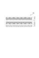
- FIG. 2 is a view showing a laminated structure of the optical fiber sheet 10 of the present embodiment.
- the optical fiber sheet 10 includes an optical fiber 11 and a wire 12 that are disposed between a first sheet 13 and a second sheet 14.
- the optical fiber 11 is a multimode optical fiber having a core made of quartz glass to which a refractive index adjusting material (for example, GeO 2 ) is added.
- the numerical aperture of the optical fiber 11 is 0.30 or less.
- the bending rigidity of the optical fiber 11 is 0.50 N ⁇ mm 2 or less.
- the optical fiber 11 is bent between the first sheet 13 and the second sheet 14.
- the optical fiber 11 having the above-mentioned numerical aperture and bending rigidity has a core diameter of 20 to 130 ⁇ m, preferably 20 to 100 ⁇ m.
- the clad provided around the core is made of resin, and the clad thickness is 10 to 10 ⁇ m.
- the design can be made within a range of 40 ⁇ m.
- the refractive index distribution of the core may be substantially uniform or may be a GI (Graded Index) type having a higher refractive index toward the center.
- the resin constituting the clad is, for example, an ultraviolet curable resin, for example, a fluorinated acrylate resin.
- An optical fiber having such a resin clad is called HPCF (Hard Plastic Clad Silica Fiber).
- the optical fiber 11 may be used in a state where the outermost layer is a clad (for example, an outer diameter of 125 ⁇ m).
- the optical fiber 11 may be used in a state where an ultraviolet curable resin is further provided around the cladding (for example, an outer diameter of 250 ⁇ m).
- the wire 12 intersects the optical fiber 11 between the first sheet 13 and the second sheet 14.
- “Intersection” means that the optical fiber 11 and the wire 12 intersect each other when viewed in a direction perpendicular to the surfaces of the sheets 13 and 14, and a force is applied from the outside in this vertical direction. This means that the wire 12 can apply a lateral pressure to the optical fiber 11.
- the optical fiber 11 generates microbend loss when a lateral pressure is applied. The larger the number of intersections between the optical fiber 11 and the wire 12, the better.
- a plurality of wires 12 may be provided, or one or a plurality of wires 12 may be bent and arranged.
- the optical fiber 11 may also serve as the wire 12 (in this case, the bending rigidity of the wire 12 is equivalent to the bending rigidity of the optical fiber 11).
- the wire 12 may be an optical fiber different from the optical fiber 11 or may be a wire made of metal or the like having a relatively high bending rigidity. In order to effectively apply a lateral pressure to the optical fiber 11, it is preferable that the bending rigidity of the wire 12 is larger than the bending rigidity of the optical fiber 11.
- the outer diameter of the wire 12 is, for example, 250 to 500 ⁇ m.
- the optical fiber 11 is fixed to the first sheet 13 with a double-sided adhesive tape 15.
- the first sheet 13 supports the optical fiber 11.
- the wire 12 is fixed to the second sheet 14 with a double-sided adhesive tape 16.
- the second sheet 14 supports the wire 12.
- Each of the first sheet 13 and the second sheet 14 may be not only a fabric (woven fabric, knitted fabric, non-woven fabric, etc.) but also various sheets such as a plastic sheet, paper, a mesh fabric having a mesh structure, and a sponge sheet.
- the sheets 13 and 14 are preferably mesh sheets having a breathable mesh structure having a large number of holes.
- the anti-slip sheet 17 provided under the second sheet 14 is used when, for example, the optical fiber sheet 10 is put in a cloth (for example, cotton) bag and the optical fiber sheet 10 slips in the bag. It is provided to prevent movement.
- Such an optical fiber sheet 10 is used, for example, to measure the respiration and heartbeat of a subject laid on a bed and laid on the bed.
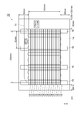
- FIG. 3 is a diagram showing a planar structure of the optical fiber sheet 10 of the present embodiment.
- This figure shows the planar structures of the optical fiber 11, the wire 12, the double-sided adhesive tape 16, and the second sheet 14, respectively.
- an xy orthogonal coordinate system is shown for convenience of explanation.
- this figure shows specific shapes and dimensions for configurations of examples and comparative examples described later.
- four double-sided adhesive tapes 16 extending in the y direction are provided on a rectangular second sheet 14 having an x direction size of 350 mm and a y direction size of 250 mm.
- the four double-sided pressure-sensitive adhesive tapes 16 each have an x-direction width of 20 mm and are provided at regular intervals with an x-direction pitch of 83 mm.
- the 16 wires 12 extend in the x direction, and are provided on the four double-sided adhesive tapes 16 at a constant interval of 10 mm in the y direction.
- the optical fiber 11 is bent a plurality of times so that the pitch in the x direction is 15 mm, and is disposed over a width in the x direction of 250 mm.
- the radius of curvature of each bent portion of the optical fiber 11 is 7.5 mm.
- a straight line portion from one bent portion to the next bent portion of the optical fiber 11 extends in the y direction, has a length of 150 mm, and intersects with the 16 wires 12.
- the measurement system 1 including the optical fiber sheet 10 configured as described above operates as follows.
- the light of constant intensity continuously output from the light source unit 20 enters the incident end of the optical fiber 11 through the optical fiber 22 and the optical connector 21.
- the light incident on the incident end is propagated through the optical fiber 11 and then exits from the exit end of the optical fiber 11.
- the light emitted from the emission end is received by the light receiving element 33 through the optical connector 31 and the optical fiber 32.
- a current signal having a value corresponding to the received light intensity is output from the light receiving element 33.
- the detection unit 30 the current signal output from the light receiving element 33 is input, the current signal is converted into a voltage signal, the voltage signal is amplified, and the voltage signal (analog signal) is AD converted to a digital signal. Then, the digital signal is transmitted to the analysis unit 40 for storage and analysis.
- the intensity of light incident on the incident end of the optical fiber 11 is constant, the intensity of light emitted from the output end of the optical fiber 11 depends on the microbend loss generated by the side pressure applied to the optical fiber 11 by the wire 12. Change. Further, the lateral pressure applied to the optical fiber 11 by the wire 12 changes according to body movements such as breathing, heartbeat, and turning over of the subject who is laid on the optical fiber sheet 10. Accordingly, a time-series voltage signal or digital signal (hereinafter referred to as “light intensity signal”) transmitted and recorded to the analysis unit 40 is analyzed (for example, Fourier analysis), so that the subject's breathing, heartbeat, and rollover, etc. Body movement can be measured. Since each of respiration and heartbeat has periodicity, the magnitude of the side pressure applied to the optical fiber 11 by the wire 12 changes periodically, and the magnitude of the light intensity signal changes periodically accordingly.
- optical fiber 11 in the first embodiment was HPCF having a core diameter of 80 ⁇ m and a resin cladding diameter of 125 ⁇ m, and this resin cladding was the outermost layer.
- This optical fiber had a numerical aperture NA of 0.30 and a flexural rigidity of 0.16 N ⁇ mm 2 .
- the optical fiber 11 used in the second embodiment is an HPCF having a core diameter of 80 ⁇ m and a resin clad diameter of 125 ⁇ m.
- An ultraviolet curable resin layer provided around the resin clad The diameter was 250 ⁇ m.
- This optical fiber had a numerical aperture NA of 0.30 and a flexural rigidity of 0.26 N ⁇ mm 2 .
- the optical fiber 11 used in the third embodiment is an HPCF having a core diameter of 50 ⁇ m and a resin cladding diameter of 125 ⁇ m.
- An ultraviolet curable resin layer provided around the resin cladding. The diameter was 250 ⁇ m.
- This optical fiber had a numerical aperture NA of 0.21 and a bending rigidity of 0.14 N ⁇ mm 2 .
- the optical fiber 11 used in the fourth embodiment is HPCF having a core diameter of 80 ⁇ m and a resin clad diameter of 125 ⁇ m.
- An ultraviolet curable resin layer provided around the resin clad The diameter was 250 ⁇ m.
- This optical fiber had a numerical aperture NA of 0.21 and a bending rigidity of 0.26 N ⁇ mm 2 .
- the optical fiber 11 used in the fifth embodiment is an HPCF having a core diameter of 100 ⁇ m and a resin cladding diameter of 125 ⁇ m.
- An ultraviolet curable resin layer provided around the resin cladding. The diameter was 250 ⁇ m.
- This optical fiber had a numerical aperture NA of 0.21 and a bending rigidity of 0.50 N ⁇ mm 2 .
- the optical fiber 11 used in the comparative example is a general-purpose multimode optical fiber having a core diameter of 50 ⁇ m and a glass clad diameter of 125 ⁇ m, and UV curing provided around the clad.
- the diameter of the mold resin layer was 250 ⁇ m.
- This optical fiber had a numerical aperture NA of 0.21 and a bending rigidity of 0.96 N ⁇ mm 2 .
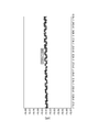
- FIG. 4 is a diagram showing a light intensity signal obtained by the analysis unit 40 in the first embodiment.
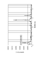
- FIG. 5 is a diagram illustrating a result of Fourier transform of the light intensity signal obtained by the analysis unit 40 in the first embodiment.
- FIG. 6 is a diagram illustrating a light intensity signal obtained by the analysis unit 40 in the second embodiment.
- FIG. 7 is a diagram illustrating a result of Fourier transform of the light intensity signal obtained by the analysis unit 40 in the second embodiment.
- FIG. 8 is a diagram illustrating a result of Fourier transform of the light intensity signal obtained by the analysis unit 40 in the comparative example. 4 and 6, the horizontal axis represents time, and the vertical axis represents the received light intensity of the light receiving element 33. Further, in each of the Fourier transform results in FIGS. 5, 7, and 8, the horizontal axis is the frequency, and the vertical axis is the size of each frequency component.
- the light intensity signal clearly shows both the long-cycle waveform component of respiration and the short-cycle waveform component of heartbeat. It was possible to measure not only the respiration (near 0.23 Hz) but also the heart rate (near 2.8 Hz) of the subject. In the case of the third example, the fourth example and the fifth example, not only the breathing of the subject but also the heart rate could be measured. On the other hand, as can be seen from FIG. 8, in the case of the comparative example, it was difficult to measure the heart rate of the subject.
- the optical fiber 11 used in the optical fiber sheet 10 is a multimode optical fiber having a core made of quartz glass to which a refractive index adjusting material is added, has a numerical aperture of 0.30 or less, and has a bending rigidity. Is 0.50 N ⁇ mm 2 or less, it is confirmed that the measurement system 1 including the optical fiber sheet 10 has sufficient sensitivity to measure not only the respiration of the subject but also the heartbeat. It was.
- DESCRIPTION OF SYMBOLS 1 ... Measuring system, 10 ... Optical fiber sheet, 11 ... Optical fiber, 12 ... Wire, 13 ... 1st sheet, 14 ... 2nd sheet, 15 ... Double-sided adhesive tape, 16 ... Double-sided adhesive tape, 17 ... Non-slip sheet, DESCRIPTION OF SYMBOLS 20 ... Light source part, 21 ... Optical connector, 22 ... Optical fiber, 30 ... Detection part, 31 ... Optical connector, 32 ... Optical fiber, 33 ... Light receiving element, 40 ... Analysis part.
Landscapes
- Health & Medical Sciences (AREA)
- Life Sciences & Earth Sciences (AREA)
- Physics & Mathematics (AREA)
- Physiology (AREA)
- Molecular Biology (AREA)
- Surgery (AREA)
- Biophysics (AREA)
- Pathology (AREA)
- Engineering & Computer Science (AREA)
- Biomedical Technology (AREA)
- Heart & Thoracic Surgery (AREA)
- Medical Informatics (AREA)
- Veterinary Medicine (AREA)
- Public Health (AREA)
- Animal Behavior & Ethology (AREA)
- General Health & Medical Sciences (AREA)
- Cardiology (AREA)
- Pulmonology (AREA)
- General Physics & Mathematics (AREA)
- Optics & Photonics (AREA)
- Measurement Of The Respiration, Hearing Ability, Form, And Blood Characteristics Of Living Organisms (AREA)
- Light Guides In General And Applications Therefor (AREA)
- Optical Fibers, Optical Fiber Cores, And Optical Fiber Bundles (AREA)
- Measuring And Recording Apparatus For Diagnosis (AREA)
Abstract
光ファイバシート10は、第1シートと第2シートとの間に挟まれて配置された光ファイバ11および線材12を備える。光ファイバ11は、屈折率調整材が添加された石英ガラスからなるコアを有するマルチモード光ファイバであり、開口数が0.30以下であり、曲げ剛性率が0.50N・mm2以下であり、第1シートと第2シートとの間において屈曲されて配置されている。線材12は、第1シートと第2シートとの間において光ファイバ11と交差している。
Description
本発明は、光ファイバシートに関するものである。
光ファイバシートを呼吸センサとして使用する技術が特許文献1~3に開示されている。特許文献1に開示された光ファイバシートは、光ファイバを布などからなるシートに固定若しくは混入したものである。この光ファイバシートは、体動によって生じた光ファイバの形状変化を、光ファイバ内を伝播する光の偏波状態の変化として捉える。この光ファイバシートを用いた場合には、S/N比がよく、呼吸によって生じるわずかな体動を検出することができ、寝返りや呼吸を明確に区別することができ、また、通常の生活環境に近い状態で呼吸の状態を観測することができるとされている。
特許文献2,3には、一般家庭の完全無拘束な通常の睡眠状態での睡眠時無呼吸症候群のスクリーニングを可能とする睡眠時無呼吸センサが開示されている。この睡眠時無呼吸センサは、光ファイバに加わる側圧により発生する過剰損失に基づく伝送光の光量変化を計測することによって体動を検出する。この睡眠時無呼吸センサは、小型かつ静音で、布団を覆うシーツの下に光ファイバシートを敷いて寝るだけのものであり、身体には一切何も付けずに簡易な操作で測定できるとされている。これらに開示されている光ファイバシートは、通常の生活環境に近い状態で呼吸の状態を観測することができる。
特許文献1~3それぞれに開示されている光ファイバシートは、呼吸を測定することができるほどの感度を有しているものの、心拍を測定することができるほど充分に高い感度を有してはいない。特許文献1~3には、光ファイバシートを用いた心拍測定について示唆はあるが、心拍測定の実施例は記載されていない。
本発明は、上記問題点を解消する為になされたものであり、感度が高く心拍測定が可能な光ファイバシートを提供することを目的とする。
本発明の光ファイバシートは、第1シートと第2シートとの間に挟まれて配置された光ファイバおよび線材を備える。この光ファイバシートでは、光ファイバは、屈折率調整材が添加された石英ガラスからなるコアを有するマルチモード光ファイバであり、開口数が0.30以下であり、曲げ剛性率が0.50N・mm2以下である。光ファイバは、第1シートと第2シートとの間において屈曲されて配置されている。線材は、第1シートと第2シートとの間において光ファイバと交差している。
本発明の光ファイバシートでは、線材の曲げ剛性率が光ファイバの曲げ剛性率以上であるのが好適である。また、光ファイバは、コアの直径が20~130μmであり、コアの周囲に設けられたクラッドが樹脂からなり、クラッドの厚みが10~40μmであるのが好適である。
本発明の光ファイバシートは感度が高く心拍測定が可能である。
以下、添付図面を参照して、本発明を実施するための形態を詳細に説明する。なお、図面の説明において同一の要素には同一の符号を付し、重複する説明を省略する。
図1は、本実施形態の光ファイバシート10を備える測定システム1の構成を示す図である。測定システム1は、光ファイバシート10、光源部20、検出部30および解析部40を備える。
光ファイバシート10は、第1シートと第2シートとの間に挟まれて配置された光ファイバ11および線材を備える。光ファイバ11は、屈折率調整材が添加された石英ガラスからなるコアを有するマルチモード光ファイバであって、第1シートと第2シートとの間において屈曲されて配置されている。光ファイバシート10の詳細については後述する。
光源部20は、一定強度の光を連続して出力する。光源部20から出た光は光ファイバ22を通って伝播した後、その光ファイバ22の先端に設けられた光コネクタ21に接続されている光ファイバ11の入射端に入射する。光源部20は、発光ダイオードやレーザダイオードから光を出力するのが好適である。
受光素子33は、光ファイバ11の出射端から出射され光コネクタ31および光ファイバ32を経て到達した光を受光して、当該受光強度に応じた値の電流信号を出力する。検出部30は、受光素子33から出力された電流信号を入力して、その電流信号を電圧信号に変換し、その電圧信号を増幅して出力する。受光素子33としてシリコンフォトダイオードが好適に用いられる。
解析部40は、検出部30から出力された電圧信号を入力し、その電圧信号(アナログ信号)をAD変換してデジタル信号として、そのデジタル信号を記憶し解析する。また、解析部40は、そのデジタル信号を表示したり、そのデジタル信号を解析して得られた結果を表示したりする。解析部40としてパーソナルコンピュータが好適に用いられる。
図2は、本実施形態の光ファイバシート10の積層構造を示す図である。光ファイバシート10は、第1シート13と第2シート14との間に挟まれて配置された光ファイバ11および線材12を備える。
光ファイバ11は、屈折率調整材(例えばGeO2)が添加された石英ガラスからなるコアを有するマルチモード光ファイバである。光ファイバ11の開口数は0.30以下である。光ファイバ11の曲げ剛性率は0.50N・mm2以下である。光ファイバ11は、第1シート13と第2シート14との間において屈曲されて配置されている。
なお、第i層のヤング率をGiとし、第i層の断面二次モーメントをIiとしたとき、曲げ剛性率Dは、
D=Σ(Gi×Ii)
となる式で表される。光ファイバの如く中心層が円柱形状を有するとともに他の各層が円筒形状を有している場合には、第i層の外径をRiとしたとき、第i層の断面二次モーメントIiは、
Ii=π(Ri 4-Ri-1 4)/64
となる式で表される。
D=Σ(Gi×Ii)
となる式で表される。光ファイバの如く中心層が円柱形状を有するとともに他の各層が円筒形状を有している場合には、第i層の外径をRiとしたとき、第i層の断面二次モーメントIiは、
Ii=π(Ri 4-Ri-1 4)/64
となる式で表される。
上記の開口数と曲げ剛性率を有する光ファイバ11は、コアの直径が20~130μm、好ましくは20~100μmであり、コアの周囲に設けられたクラッドが樹脂からなり、クラッドの厚みが10~40μmである範囲で設計できる。コアの屈折率分布は、略一様であってもよいし、中心ほど屈折率が高いGI(Graded Index)型であってもよい。クラッドを構成する樹脂は、例えば紫外線硬化型樹脂であり、例えばフッ化アクリレート樹脂である。このような樹脂からなるクラッドを有する光ファイバは、HPCF(Hard Plastic Clad Silica Fiber)と呼ばれている。
光ファイバ11は、最外層がクラッドである状態(例えば外径125μm)で用いられてもよい。また、光ファイバ11は、クラッドの周囲に更に紫外線硬化型樹脂が設けられた状態(例えば外径250μm)で用いられてもよい。
線材12は、第1シート13と第2シート14との間において光ファイバ11と交差している。なお、「交差」とは、シート13,14の面に垂直な方向に見たときに光ファイバ11と線材12とが互いに交差していて、この垂直方向に外から力が加えられたときに線材12が光ファイバ11に側圧を与え得ることを意味する。光ファイバ11は、側圧が与えられることによりマイクロベンドロスを生じる。光ファイバ11と線材12との交差の数は多いほど好ましい。
複数本の線材12が設けられていてもよいし、1本または複数本の線材12が屈曲されて配置されていてもよい。光ファイバ11が線材12を兼ねていてもよい(この場合、線材12の曲げ剛性率は光ファイバ11の曲げ剛性率と同等)。線材12は、光ファイバ11とは別の光ファイバであってもよいし、曲げ剛性率が比較的高い金属等のワイヤであってもよい。光ファイバ11に対し効果的に側圧を与えるためには、線材12の曲げ剛性率は光ファイバ11の曲げ剛性率より大きいのが好ましい。線材12の外径は例えば250~500μmである。
光ファイバ11は、第1シート13に対し両面粘着テープ15により固定されている。第1シート13は光ファイバ11を支持する。線材12は、第2シート14に対し両面粘着テープ16により固定されている。第2シート14は線材12を支持する。
第1シート13および第2シート14それぞれは、布帛(織布、編み布、不織布など)だけでなく、プラスチックシート、紙、メッシュ構造を有する網布、スポンジシートなどの各種シートであってよい。シート13,14は、多数の空孔を有する通気性のあるメッシュ構造の網シートであるのが好適である。
第2シート14の下に設けられる滑り止めシート17は、例えば布製(例えば綿製)の袋に光ファイバシート10が入れられて用いられる場合に、その袋の中で光ファイバシート10が滑って移動することを防止するために設けられている。このような光ファイバシート10は、例えばベッドの上に敷かれ、その上に寝かされた被験者の呼吸や心拍を測定するために用いられる。
図3は、本実施形態の光ファイバシート10の平面構造を示す図である。同図は、特に光ファイバ11,線材12,両面粘着テープ16および第2シート14それぞれの平面構造を示す。同図には、説明の便宜のためにxy直交座標系が示されている。また、同図は、後述する実施例および比較例の構成について具体的な形状および寸法を示している。
同図に示される構成例では、x方向サイズ350mmでy方向サイズ250mmの矩形の第2シート14上に、y方向に延在する4本の両面粘着テープ16が設けられている。4本の両面粘着テープ16は、各々のx方向幅が20mmで、x方向ピッチ83mmの一定間隔で設けられている。16本の線材12は、各々x方向に延在し、y方向ピッチ10mmの一定間隔で、4本の両面粘着テープ16上に設けられている。
光ファイバ11は、x方向ピッチが15mmとなるように複数回屈曲されて、x方向幅250mmに亘って配置されている。光ファイバ11の各屈曲部の曲率半径は7.5mmである。光ファイバ11の或る屈曲部から次の屈曲部までの間の直線部は、y方向に延在し、長さ150mmであり、16本の線材12と交差している。
以上のように構成される光ファイバシート10を備える測定システム1は以下のように動作する。光源部20から連続的に出力された一定強度の光は、光ファイバ22および光コネクタ21を経て、光ファイバ11の入射端に入射する。その入射端に入射された光は、光ファイバ11により伝播された後、光ファイバ11の出射端から出射する。その出射端から出射した光は、光コネクタ31および光ファイバ32を経て、受光素子33により受光される。その受光強度に応じた値の電流信号が受光素子33から出力される。検出部30では、受光素子33から出力された電流信号が入力され、その電流信号が電圧信号に変換され、その電圧信号が増幅され、その電圧信号(アナログ信号)がAD変換されてデジタル信号とされて、そのデジタル信号が解析部40に送信されて記憶され解析される。
光ファイバ11の入射端に入射する光の強度は一定であるが、光ファイバ11の出射端から出射する光の強度は、線材12により光ファイバ11に与えられる側圧によって生じるマイクロベンドロスに応じて変化する。また、線材12により光ファイバ11に与えられる側圧は、光ファイバシート10の上に寝かされた被験者の呼吸,心拍および寝返り等の体動に応じて変化する。したがって、解析部40に送信されて記録された時系列の電圧信号またはデジタル信号(以下「光強度信号」という。)が解析(例えばフーリエ解析)されることにより、被験者の呼吸,心拍および寝返り等の体動が測定され得る。呼吸および心拍それぞれは周期性を有するので、それに応じて、線材12により光ファイバ11に与えられる側圧の大きさは周期的に変化し、光強度信号の大きさは周期的に変化する。
次に、光ファイバ11として種々のものを使用して光ファイバシート10を試作し、その試作した光ファイバシート10を用いて被験者の呼吸および心拍の測定を行った結果について説明する。なお、線材12の曲げ剛性率は1N・mm2であった。
第1実施例において光ファイバ11として用いられたものは、HPCFであって、コア径が80μmであり、樹脂クラッド径が125μmであって、この樹脂クラッドが最外層であった。この光ファイバは、開口数NAが0.30であり、曲げ剛性率が0.16N・mm2であった。
第2実施例において光ファイバ11として用いられたものは、HPCFであって、コア径が80μmであり、樹脂クラッド径が125μmであり、この樹脂クラッドの周囲に設けられた紫外線硬化型樹脂層の径が250μmであった。この光ファイバは、開口数NAが0.30であり、曲げ剛性率が0.26N・mm2であった。
第3実施例において光ファイバ11として用いられたものは、HPCFであって、コア径が50μmであり、樹脂クラッド径が125μmであり、この樹脂クラッドの周囲に設けられた紫外線硬化型樹脂層の径が250μmであった。この光ファイバは、開口数NAが0.21であり、曲げ剛性率が0.14N・mm2であった。
第4実施例において光ファイバ11として用いられたものは、HPCFであって、コア径が80μmであり、樹脂クラッド径が125μmであり、この樹脂クラッドの周囲に設けられた紫外線硬化型樹脂層の径が250μmであった。この光ファイバは、開口数NAが0.21であり、曲げ剛性率が0.26N・mm2であった。
第5実施例において光ファイバ11として用いられたものは、HPCFであって、コア径が100μmであり、樹脂クラッド径が125μmであり、この樹脂クラッドの周囲に設けられた紫外線硬化型樹脂層の径が250μmであった。この光ファイバは、開口数NAが0.21であり、曲げ剛性率が0.50N・mm2であった。
比較例において光ファイバ11として用いられたものは、汎用マルチモード光ファイバであって、コア径が50μmであり、ガラスからなるクラッドの径が125μmであり、このクラッドの周囲に設けられた紫外線硬化型樹脂層の径が250μmであった。この光ファイバは、開口数NAが0.21であり、曲げ剛性率が0.96N・mm2であった。
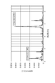
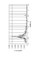
図4は、第1実施例において解析部40で得られた光強度信号を示す図である。図5は、第1実施例において解析部40で得られた光強度信号をフーリエ変換した結果を示す図である。図6は、第2実施例において解析部40で得られた光強度信号を示す図である。図7は、第2実施例において解析部40で得られた光強度信号をフーリエ変換した結果を示す図である。図8は、比較例において解析部40で得られた光強度信号をフーリエ変換した結果を示す図である。図4および図6それぞれの光強度信号の図において、横軸は時刻であり、縦軸は受光素子33の受光強度である。また、図5,図7および図8それぞれのフーリエ変換結果の図において、横軸は周波数であり、縦軸は各周波数成分の大きさである。
図4~図7から判るように、第1実施例および第2実施例の何れの場合においても、光強度信号には呼吸の長周期の波形成分および心拍の短周期の波形成分の双方が明確に存在していることが確認され、被験者の呼吸(0.23Hz付近)だけでなく心拍(2.8Hz付近)をも測定することが可能であった。第3実施例,第4実施例および第5実施例の場合においても、被験者の呼吸だけでなく心拍も測定が可能であった。一方、図8から判るように、比較例の場合には、被験者の心拍の測定が困難であった。
その他にも種々のものを光ファイバ11として使用して光ファイバシート10を試作し評価した。その結果、光ファイバシート10で用いられる光ファイバ11は、屈折率調整材が添加された石英ガラスからなるコアを有するマルチモード光ファイバであり、開口数が0.30以下であり、曲げ剛性率が0.50N・mm2以下であることにより、この光ファイバシート10を備える測定システム1は、被験者の呼吸だけでなく心拍をも測定することができるほどの充分な感度を有することが確認された。
1…測定システム、10…光ファイバシート、11…光ファイバ、12…線材、13…第1シート、14…第2シート、15…両面粘着テープ、16…両面粘着テープ、17…滑り止めシート、20…光源部、21…光コネクタ、22…光ファイバ、30…検出部、31…光コネクタ、32…光ファイバ、33…受光素子、40…解析部。
Claims (3)
- 第1シートと第2シートとの間に挟まれて配置された光ファイバおよび線材を備え、
前記光ファイバは、屈折率調整材が添加された石英ガラスからなるコアを有するマルチモード光ファイバであり、開口数が0.30以下であり、曲げ剛性率が0.50N・mm2以下であり、前記第1シートと前記第2シートとの間において屈曲されて配置されており、
前記線材は、前記第1シートと前記第2シートとの間において前記光ファイバと交差している、光ファイバシート。 - 前記線材の曲げ剛性率が前記光ファイバの曲げ剛性率以上である、請求項1に記載の光ファイバシート。
- 前記光ファイバは、前記コアの直径が20~130μmであり、前記コアの周囲に設けられたクラッドが樹脂からなり、前記クラッドの厚みが10~40μmである、請求項1又は2に記載の光ファイバシート。
Priority Applications (1)
| Application Number | Priority Date | Filing Date | Title |
|---|---|---|---|
| US14/349,445 US9186078B2 (en) | 2011-10-05 | 2012-10-03 | Optical fiber sheet |
Applications Claiming Priority (2)
| Application Number | Priority Date | Filing Date | Title |
|---|---|---|---|
| JP2011220912A JP5324633B2 (ja) | 2011-10-05 | 2011-10-05 | 光ファイバシート |
| JP2011-220912 | 2011-10-05 |
Publications (1)
| Publication Number | Publication Date |
|---|---|
| WO2013051602A1 true WO2013051602A1 (ja) | 2013-04-11 |
Family
ID=48043756
Family Applications (1)
| Application Number | Title | Priority Date | Filing Date |
|---|---|---|---|
| PCT/JP2012/075637 Ceased WO2013051602A1 (ja) | 2011-10-05 | 2012-10-03 | 光ファイバシート |
Country Status (3)
| Country | Link |
|---|---|
| US (1) | US9186078B2 (ja) |
| JP (1) | JP5324633B2 (ja) |
| WO (1) | WO2013051602A1 (ja) |
Cited By (1)
| Publication number | Priority date | Publication date | Assignee | Title |
|---|---|---|---|---|
| WO2016106912A1 (zh) * | 2014-12-31 | 2016-07-07 | 汇嘉健康生活科技股份有限公司 | 光纤式连续检测型血压传感器及其穿戴装置 |
Families Citing this family (6)
| Publication number | Priority date | Publication date | Assignee | Title |
|---|---|---|---|---|
| US9297951B2 (en) * | 2012-02-27 | 2016-03-29 | Sumitomo Bakelite Co., Ltd. | Optical waveguide, optical wiring component, optical waveguide module and electronic device |
| WO2015112095A1 (en) * | 2014-01-23 | 2015-07-30 | Agency For Science, Technology And Research | Smart belt for breathing and heart rate monitoring |
| CN105769118B (zh) * | 2014-12-15 | 2019-07-05 | 汇嘉健康生活科技股份有限公司 | 光纤感应层及其监测系统 |
| JP2017038840A (ja) * | 2015-08-21 | 2017-02-23 | 住友電気工業株式会社 | 嚥下運動モニタリングセンサ |
| WO2017035452A1 (en) * | 2015-08-27 | 2017-03-02 | Darma Inc. | Fiber-optic sensors and methods for monitoring micro-movements |
| CN111281389B (zh) * | 2018-12-10 | 2022-11-08 | 深圳麦格米特电气股份有限公司 | 一种智能呼吸监测床垫 |
Citations (4)
| Publication number | Priority date | Publication date | Assignee | Title |
|---|---|---|---|---|
| JP2008206908A (ja) * | 2007-02-28 | 2008-09-11 | Matsushita Electric Ind Co Ltd | 生体信号検出装置及びそれを用いた電気機器 |
| JP2008284001A (ja) * | 2007-05-15 | 2008-11-27 | Panasonic Corp | 生体信号検出装置及びそれを用いた就寝装置 |
| JP2010131340A (ja) * | 2008-12-05 | 2010-06-17 | Nariyuki Mitachi | 睡眠時無呼吸センサ用光ファイバシート |
| JP2012065911A (ja) * | 2010-09-24 | 2012-04-05 | Nariyuki Mitachi | 光ファイバシート |
Family Cites Families (8)
| Publication number | Priority date | Publication date | Assignee | Title |
|---|---|---|---|---|
| US5291013A (en) * | 1991-12-06 | 1994-03-01 | Alamed Corporation | Fiber optical monitor for detecting normal breathing and heartbeat motion based on changes in speckle patterns |
| JP2987247B2 (ja) * | 1991-12-09 | 1999-12-06 | バーグ・テクノロジー・インコーポレーテッド | 光ファイバー接続装置 |
| US6816266B2 (en) * | 2000-02-08 | 2004-11-09 | Deepak Varshneya | Fiber optic interferometric vital sign monitor for use in magnetic resonance imaging, confined care facilities and in-hospital |
| JP2003014998A (ja) * | 2001-06-29 | 2003-01-15 | Fujikura Ltd | 光ファイバ心線 |
| JP4554476B2 (ja) | 2005-08-30 | 2010-09-29 | 財団法人電力中央研究所 | 生体活動監視方法と、これに用いる光ファイバ式平板状体センサ |
| JP2007144070A (ja) | 2005-11-24 | 2007-06-14 | Nariyuki Mitachi | 光ファイバを用いた睡眠時無呼吸センサー |
| SG10201404690RA (en) * | 2009-08-06 | 2014-10-30 | Agency Science Tech & Res | A vital signs detecting device and a method for detecting vital signs |
| JP2012119836A (ja) * | 2010-11-30 | 2012-06-21 | Fuji Xerox Co Ltd | 送信装置及び送受信装置 |
-
2011
- 2011-10-05 JP JP2011220912A patent/JP5324633B2/ja not_active Expired - Fee Related
-
2012
- 2012-10-03 US US14/349,445 patent/US9186078B2/en not_active Expired - Fee Related
- 2012-10-03 WO PCT/JP2012/075637 patent/WO2013051602A1/ja not_active Ceased
Patent Citations (4)
| Publication number | Priority date | Publication date | Assignee | Title |
|---|---|---|---|---|
| JP2008206908A (ja) * | 2007-02-28 | 2008-09-11 | Matsushita Electric Ind Co Ltd | 生体信号検出装置及びそれを用いた電気機器 |
| JP2008284001A (ja) * | 2007-05-15 | 2008-11-27 | Panasonic Corp | 生体信号検出装置及びそれを用いた就寝装置 |
| JP2010131340A (ja) * | 2008-12-05 | 2010-06-17 | Nariyuki Mitachi | 睡眠時無呼吸センサ用光ファイバシート |
| JP2012065911A (ja) * | 2010-09-24 | 2012-04-05 | Nariyuki Mitachi | 光ファイバシート |
Cited By (2)
| Publication number | Priority date | Publication date | Assignee | Title |
|---|---|---|---|---|
| WO2016106912A1 (zh) * | 2014-12-31 | 2016-07-07 | 汇嘉健康生活科技股份有限公司 | 光纤式连续检测型血压传感器及其穿戴装置 |
| US11607141B2 (en) | 2014-12-31 | 2023-03-21 | Huijia Health Life Technology Co., Ltd. | Optical fiber blood pressure continuous detection wristband and wearing apparatus |
Also Published As
| Publication number | Publication date |
|---|---|
| JP5324633B2 (ja) | 2013-10-23 |
| US9186078B2 (en) | 2015-11-17 |
| US20140270669A1 (en) | 2014-09-18 |
| JP2013080154A (ja) | 2013-05-02 |
Similar Documents
| Publication | Publication Date | Title |
|---|---|---|
| JP5324633B2 (ja) | 光ファイバシート | |
| Wang et al. | Optical microfiber intelligent sensor: wearable cardiorespiratory and behavior monitoring with a flexible wave-shaped polymer optical microfiber | |
| Li et al. | A simple optical fiber interferometer based breathing sensor | |
| Favero et al. | Microstructured optical fiber interferometric breathing sensor | |
| Massaroni et al. | Medical smart textiles based on fiber optic technology: an overview | |
| US9655526B2 (en) | Vital signs fiber optic sensor systems and methods | |
| JP6504685B2 (ja) | 光ファイバーセンサ及び微動の監視方法 | |
| Hu et al. | Design and experiment of an optical fiber micro bend sensor for respiration monitoring | |
| US20100313668A1 (en) | Fiber strain sensor and measurement system for repeated large deformation | |
| CN102573615B (zh) | 生命特征检测装置和用于检测生命特征的方法 | |
| Wang et al. | A review of multimode interference in tapered optical fibers and related applications | |
| CN105277135B (zh) | 一种具有温度不敏感特性的高灵敏度光纤曲率传感结构 | |
| Li et al. | A review of wearable optical fiber sensors for rehabilitation monitoring | |
| Xue et al. | Real-time monitoring of human breathing using wearable tilted fiber grating curvature sensors | |
| Li et al. | A sensitivity-enhanced flexible acoustic sensor using side-polished fiber Bragg grating | |
| Yao et al. | Advances in multicore fiber interferometric sensors | |
| US20200400886A1 (en) | Elastomeric lightguide coupling for continuous position localization in 1,2, and 3d | |
| JP2010530963A5 (ja) | ||
| Wo et al. | Noninvasive respiration movement sensor based on distributed Bragg reflector fiber laser with beat frequency interrogation | |
| CN216206440U (zh) | 一种光纤生命体征传感器 | |
| CN103528733B (zh) | 实时监测柔性绳索载荷和温度的梭形传感器 | |
| Yamazaki et al. | Optical strain gauge-based on a hetero-core fiber macro-bending sensor | |
| CN114675053A (zh) | 基于啁啾光纤光栅的强度解调型风速传感器 | |
| Wo et al. | Biconical-taper-assisted fiber interferometer with modes coupling enhancement for high-sensitive curvature measurement | |
| Wang et al. | Optical fiber microvibration sensor design for wearable multipoint breathing monitoring |
Legal Events
| Date | Code | Title | Description |
|---|---|---|---|
| 121 | Ep: the epo has been informed by wipo that ep was designated in this application |
Ref document number: 12838487 Country of ref document: EP Kind code of ref document: A1 |
|
| WWE | Wipo information: entry into national phase |
Ref document number: 14349445 Country of ref document: US |
|
| NENP | Non-entry into the national phase |
Ref country code: DE |
|
| 122 | Ep: pct application non-entry in european phase |
Ref document number: 12838487 Country of ref document: EP Kind code of ref document: A1 |