WO2013051621A1 - Dispositif d'alimentation en matériau granulaire - Google Patents
Dispositif d'alimentation en matériau granulaire Download PDFInfo
- Publication number
- WO2013051621A1 WO2013051621A1 PCT/JP2012/075686 JP2012075686W WO2013051621A1 WO 2013051621 A1 WO2013051621 A1 WO 2013051621A1 JP 2012075686 W JP2012075686 W JP 2012075686W WO 2013051621 A1 WO2013051621 A1 WO 2013051621A1
- Authority
- WO
- WIPO (PCT)
- Prior art keywords
- gas
- granular material
- nitrogen
- guide tube
- rotating shaft
- Prior art date
- Legal status (The legal status is an assumption and is not a legal conclusion. Google has not performed a legal analysis and makes no representation as to the accuracy of the status listed.)
- Ceased
Links
Images


Classifications
-
- B—PERFORMING OPERATIONS; TRANSPORTING
- B65—CONVEYING; PACKING; STORING; HANDLING THIN OR FILAMENTARY MATERIAL
- B65D—CONTAINERS FOR STORAGE OR TRANSPORT OF ARTICLES OR MATERIALS, e.g. BAGS, BARRELS, BOTTLES, BOXES, CANS, CARTONS, CRATES, DRUMS, JARS, TANKS, HOPPERS, FORWARDING CONTAINERS; ACCESSORIES, CLOSURES, OR FITTINGS THEREFOR; PACKAGING ELEMENTS; PACKAGES
- B65D83/00—Containers or packages with special means for dispensing contents
- B65D83/06—Containers or packages with special means for dispensing contents for dispensing powdered or granular material
-
- B—PERFORMING OPERATIONS; TRANSPORTING
- B65—CONVEYING; PACKING; STORING; HANDLING THIN OR FILAMENTARY MATERIAL
- B65B—MACHINES, APPARATUS OR DEVICES FOR, OR METHODS OF, PACKAGING ARTICLES OR MATERIALS; UNPACKING
- B65B39/00—Nozzles, funnels or guides for introducing articles or materials into containers or wrappers
- B65B39/04—Nozzles, funnels or guides for introducing articles or materials into containers or wrappers having air-escape, or air-withdrawal, passages
-
- B—PERFORMING OPERATIONS; TRANSPORTING
- B65—CONVEYING; PACKING; STORING; HANDLING THIN OR FILAMENTARY MATERIAL
- B65B—MACHINES, APPARATUS OR DEVICES FOR, OR METHODS OF, PACKAGING ARTICLES OR MATERIALS; UNPACKING
- B65B1/00—Packaging fluent solid material, e.g. powders, granular or loose fibrous material, loose masses of small articles, in individual containers or receptacles, e.g. bags, sacks, boxes, cartons, cans, or jars
- B65B1/04—Methods of, or means for, filling the material into the containers or receptacles
- B65B1/10—Methods of, or means for, filling the material into the containers or receptacles by rotary feeders
- B65B1/12—Methods of, or means for, filling the material into the containers or receptacles by rotary feeders of screw type
-
- B—PERFORMING OPERATIONS; TRANSPORTING
- B65—CONVEYING; PACKING; STORING; HANDLING THIN OR FILAMENTARY MATERIAL
- B65B—MACHINES, APPARATUS OR DEVICES FOR, OR METHODS OF, PACKAGING ARTICLES OR MATERIALS; UNPACKING
- B65B1/00—Packaging fluent solid material, e.g. powders, granular or loose fibrous material, loose masses of small articles, in individual containers or receptacles, e.g. bags, sacks, boxes, cartons, cans, or jars
- B65B1/04—Methods of, or means for, filling the material into the containers or receptacles
- B65B1/16—Methods of, or means for, filling the material into the containers or receptacles by pneumatic means, e.g. by suction
-
- B—PERFORMING OPERATIONS; TRANSPORTING
- B65—CONVEYING; PACKING; STORING; HANDLING THIN OR FILAMENTARY MATERIAL
- B65B—MACHINES, APPARATUS OR DEVICES FOR, OR METHODS OF, PACKAGING ARTICLES OR MATERIALS; UNPACKING
- B65B31/00—Packaging articles or materials under special atmospheric or gaseous conditions; Adding propellants to aerosol containers
- B65B31/04—Evacuating, pressurising or gasifying filled containers or wrappers by means of nozzles through which air or other gas, e.g. an inert gas, is withdrawn or supplied
- B65B31/041—Evacuating, pressurising or gasifying filled containers or wrappers by means of nozzles through which air or other gas, e.g. an inert gas, is withdrawn or supplied the nozzles acting from above on containers or wrappers open at their top
-
- B—PERFORMING OPERATIONS; TRANSPORTING
- B65—CONVEYING; PACKING; STORING; HANDLING THIN OR FILAMENTARY MATERIAL
- B65B—MACHINES, APPARATUS OR DEVICES FOR, OR METHODS OF, PACKAGING ARTICLES OR MATERIALS; UNPACKING
- B65B31/00—Packaging articles or materials under special atmospheric or gaseous conditions; Adding propellants to aerosol containers
- B65B31/04—Evacuating, pressurising or gasifying filled containers or wrappers by means of nozzles through which air or other gas, e.g. an inert gas, is withdrawn or supplied
- B65B31/044—Evacuating, pressurising or gasifying filled containers or wrappers by means of nozzles through which air or other gas, e.g. an inert gas, is withdrawn or supplied the nozzles being combined with a filling device
-
- B—PERFORMING OPERATIONS; TRANSPORTING
- B65—CONVEYING; PACKING; STORING; HANDLING THIN OR FILAMENTARY MATERIAL
- B65B—MACHINES, APPARATUS OR DEVICES FOR, OR METHODS OF, PACKAGING ARTICLES OR MATERIALS; UNPACKING
- B65B37/00—Supplying or feeding fluent-solid, plastic, or liquid material, or loose masses of small articles, to be packaged
- B65B37/08—Supplying or feeding fluent-solid, plastic, or liquid material, or loose masses of small articles, to be packaged by rotary feeders
- B65B37/10—Supplying or feeding fluent-solid, plastic, or liquid material, or loose masses of small articles, to be packaged by rotary feeders of screw type
-
- B—PERFORMING OPERATIONS; TRANSPORTING
- B65—CONVEYING; PACKING; STORING; HANDLING THIN OR FILAMENTARY MATERIAL
- B65B—MACHINES, APPARATUS OR DEVICES FOR, OR METHODS OF, PACKAGING ARTICLES OR MATERIALS; UNPACKING
- B65B39/00—Nozzles, funnels or guides for introducing articles or materials into containers or wrappers
- B65B39/007—Guides or funnels for introducing articles into containers or wrappers
Definitions
- This invention relates to the granular material supply apparatus which supplies a granular material.
- a powder supply device for supplying powder, granules, etc. to a storage bag.
- the granular material is often stored in a storage bag together with air and sealed.
- the granular material if it is sealed in a storage bag for a long time, it may be oxidized and deteriorated or hardened by air.
- Examples of such powders include wheat flour, skim milk powder, and toner containing a magnetic material for a copying machine.
- Patent Document 1 there is a powder supply device that removes air (degass) and stores the powder in a storage bag.
- Patent Document 1 JP 2011-84311 A
- the conventional granular material supply device has a limit in increasing the deaeration rate, and has a limit in extending the quality assurance period of the granular material.
- the present invention provides a granular material supply device that bleeds air between granular particles, ejects an inert gas toward the outside from the granular material, and includes the inert gas in the granular material. It is to provide.
- the granular material supply apparatus includes a guide tube that guides the granular material, in which a plurality of through holes for guiding an internal gas to the outside are formed, and a portion in which the through hole of the guide tube is formed.
- a filter that allows the gas in the guide tube to flow to the outside through the through hole, and prevents the granular material in the guide tube from leaking to the outside from the through hole;
- a gas supply unit that supplies an inert gas, a rotating shaft that is positioned and rotated in the guide tube, and is rotated on the rotating shaft and rotated in the guide tube by rotation of the rotating shaft.
- the rotating shaft has a gas guide path for guiding the inert gas supplied by the gas supply unit, and the inert gas guided by the gas guide path is ejected to form a granular material.
- the granular material supply device of the present invention is not in contact with the granular material from the gas supply port of the gas guide path toward the outside while conveying the granular material by the auger in the guide tube. Since the active gas is contained and the gas in the guide cylinder is sucked outside through the through hole and the filter by the suction device, the inert gas can be filled in the granular material, and oxidation of the granular material, Solidification and the like can be prevented, and the quality of the powder can be kept constant for a long period of time.
- the rotating shaft has a plurality of the gas supply ports along an axial direction of the rotating shaft, and the guide tube has a plurality of the through holes facing the plurality of gas supply ports in the axial direction. It is preferable to form along.
- the granular material supply device can efficiently perform the air venting of the granular material and the filling of the inert gas at the same time.
- the rotating shaft has a plurality of gas supply ports over the entire length of the rotating shaft in the axial direction, and the guide tube forms the plurality of through holes over the entire length of the guide tube. Is preferred.
- the guide tube is formed with a gas non-leakage portion facing the gas supply port, in which the through-hole is not formed, and a plurality of the through-holes on the upstream side in the axial direction with respect to the gas non-leakage portion. It is preferable to include an upper suction portion that is formed and a lower suction portion in which a plurality of the through holes are formed on the downstream side in the axial direction with respect to the gas non-leakage portion.
- the granular material supply device removes the air contained in the granular material at the upper suction part while conveying the granular material by the auger in the guide tube, and the powder from the gas supply port at the gas non-leakage part.
- Inert gas is included in the granule, and the residual air and inert gas contained in the granule are sucked in the lower suction part.
- the quality of the granules can be kept constant for a long time.
- the guide tube is provided with a gas outlet for injecting an inert gas at the tip.
- the air in the storage bag for supplying the granular material can be reduced, and instead, the inert gas can be filled into the storage bag, and the granular material when stored in the storage bag can be used.
- the quality assurance period of the granular material can be lengthened.
- the inert gas is preferably nitrogen gas.
- the oxidation of the powder can be prevented by the nitrogen gas, and the quality assurance period of the powder can be extended.
- the said granular material is grain flour, for example.
- the powder particles are, for example, image forming toner.
- FIG. 2 is a cross-sectional view taken along line AA in FIG. 1.
- FIG. 6 is a cross-sectional view taken along the line BB in FIG. 1.
- FIG. 4 is a cross-sectional view taken along the line CC of FIGS. 2 and 3, (A) is an overall view, and (B) is a cross-sectional view of a negative pressure chamber portion.
- FIG. 4 is a cross-sectional view taken along the line DD in FIGS. 2 and 3.
- FIG. 4 is a cross-sectional view taken along the line EE in FIGS. 2 and 3.
- FIG. 4 is a state diagram of the granular material supply device before supplying the granular material to the storage bag, and is a cross-sectional view taken along the line DD in FIGS. 2 and 3.
- FIG. 4 is a state diagram of the granular material supply device that is supplying the granular material to the storage bag, and is a cross-sectional view taken along the line CC in FIGS. 2 and 3.
- It is a state figure of the granular material supply apparatus immediately after completion
- FIG. 11 is a cross-sectional view taken along line JJ in FIG. 10.
- 11 and 12 are cross-sectional views taken along the line KK in FIG. 11, (A) is an overall view, and (B) is a partial cross-sectional view of the negative pressure chamber.
- 11 and 12 are cross-sectional views taken along line LL in FIG. 11 and FIG. 12, (A) is an overall view, and (B) is a partial cross-sectional view of a negative pressure chamber.
- FIG. 13 is a cross-sectional view taken along the line MM in FIGS. 11 and 12.
- FIG. 13 is a cross-sectional view taken along line NN in FIGS. 11 and 12.
- the powder supply device 11 is a device that supplies or fills the storage bag S with powder.
- the powder particles include cereal powders such as wheat flour and nonfat dry milk, and image forming toner containing a magnetic material for a copying machine.
- the granular material supply device 11 is erected on the fixing member 12.
- an elevating shaft 14 is provided so as to be movable up and down. When the handle 15 is rotated, the elevating shaft 14 elevates the column 13 by an elevating mechanism (not shown).
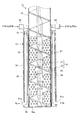
- the elevating shaft 14 is provided with a hopper 17 and a cylindrical guide tube 18 through a bracket 16.
- the hopper 17 stores powder particles.
- a motor (not shown) that rotates an auger (also called a screw) 19 and a cover 20 that houses the motor are provided at the upper end portion of the elevating shaft 14.
- the auger 19 is positioned in the guide cylinder 18 and rotates.
- the auger 19 rotates in the guide cylinder 18 by the rotation of the rotation shaft 21 provided on the rotation shaft 21.
- the blades 22 for conveying.
- the blades 22 are formed in a circular shape when viewed from the end of the rotating shaft 21 as shown in FIG.
- the rotating shaft 21 is rotatably supported by the hopper 17 and the cover 20.
- the rotating shaft 21 extends through the cover 20 and the hopper 17 to the vicinity of the powder outlet 18a of the guide cylinder 18.
- a nitrogen supply path (gas) for guiding nitrogen gas (inert gas) N 2 supplied by a nitrogen gas supply device (gas supply unit) 27 from the upper end to the substantially lower end of the rotary shaft 21 is provided at the axis of the rotary shaft 21.
- Guideway) 23 is formed.
- nitrogen outlets (gas supply ports) 26 are formed radially around the nitrogen supply path 23 as shown in FIG. 3, and the axial direction of the rotary shaft 21 as shown in FIG. A plurality are formed along.
- the nitrogen jet port 26 is configured so that nitrogen gas guided by the nitrogen supply path 23 is jetted and nitrogen particles are contained in the powder.
- the head of the rotating shaft 21 is connected to a nitrogen gas supply device 27 that supplies nitrogen gas via a rotatable elbow 25 and a nitrogen supply pipe 24.
- the guide cylinder 18 is formed in a cylindrical shape, and guides the granular material conveyed by the auger 19 from the hopper 17 to the storage bag S.
- the guide tube 18 is formed with a plurality of air / gas vent holes (through holes) 28 for guiding the internal gas to the outside.
- a plurality of air / gas vent holes 28 are formed from the portion below the hopper 17 of the guide cylinder 18 to the vicinity of the powder outlet 18a at the tip (lower end in FIG. 4).
- the gas includes air contained in the granular material, nitrogen gas ejected from the nitrogen ejection port 26, and the like.
- a cylindrical filter 29 is provided on the outer periphery of the portion of the guide tube 18 where the air / gas vent hole 28 is formed.
- the filter 29 allows the gas in the guide cylinder 18 to flow to the outside through the air / gas vent hole 28, and prevents the powder particles in the guide cylinder 18 from leaking to the outside through the air / gas vent hole 28. It comes to stop.
- the portion of the guide tube 18 where the air / gas vent hole 28 is formed is weak in strength. Further, it is necessary to protect the outer peripheral portion of the cylindrical filter 29. Therefore, a reinforcing cylinder 71 that reinforces the guide cylinder 18 and protects the outer periphery of the filter 29 is provided outside the filter 29 with the guide cylinder 18 sandwiching the filter 29 therebetween.
- the reinforcing cylinder 71 has a length that covers the filter 29.
- the reinforcing cylinder 71 also has a plurality of air / gas vent holes 72 facing the air / gas vent holes 28 formed in the guide cylinder 18.
- the air / gas vent hole 72 also guides the gas inside the guide tube 18 to the outside.
- a negative pressure chamber 73 is provided on the outer periphery of the reinforcing cylinder 71.
- the negative pressure chamber 73 is formed by an outer peripheral cylinder 74, an upper lid 75, and a lower lid 76.
- the outer peripheral cylinder 74 is separated from the reinforcing cylinder 71, and the upper part is attached to the guide cylinder 18 by a ring-shaped upper lid 75, and the lower part is provided to the granular material discharge port 18 a of the guide cylinder 18 by a ring-shaped lower lid 76.
- the negative pressure chamber 73 is formed in a region wider than a region where the air / gas vent holes 28 and 72 are formed. FIG.
- FIG. 4B is a diagram showing the positional relationship among the guide cylinder 18, the filter 29, the reinforcing cylinder 71, and the outer peripheral cylinder 74.
- the reinforcement cylinder 71 is not necessarily required.
- the gas passage hole 77 formed in the upper lid 75 of the negative pressure chamber 73 is provided with a negative pressure elbow 78 that connects the negative pressure chamber 73 and an air / gas suction device (suction device) 79. As shown in FIGS. 2 and 3, the negative pressure elbows 78 are provided at intervals of 90 degrees.
- the negative pressure chamber 73 on the outer periphery of the guide cylinder 18 has a nitrogen lower supply pipe 51 used when supplying nitrogen gas to the bottom of the storage bag S, and a nitrogen gas at the top of the storage bag S.
- Nitrogen upper supply pipe 61 used when supplying nitrogen.
- the nitrogen lower supply pipe 51 is formed straight and supported by the upper lid 75 and the lower lid 76.
- the nitrogen upper supply pipe 61 is formed in an L shape with the tip portion facing outward, and is supported by the upper lid 75 and the outer peripheral cylinder 74.
- the lower nitrogen supply pipe 51 is connected to the nitrogen gas supply device 27 by an elbow 52 provided on the upper part of the lower nitrogen supply pipe 51.
- the nitrogen upper supply pipe 61 is also connected to the nitrogen gas supply device 27 via an elbow 62 provided on the upper part of the nitrogen upper supply pipe 61 and a nitrogen supply pipe (not shown).
- two nitrogen lower supply pipes 51 and two nitrogen upper supply pipes 61 are alternately arranged at intervals of 90 degrees. Therefore, in FIG. 2, eight elbows 52, 78, 62, 78, 52, 78, 62, 78 are provided at equal intervals on the upper lid 75 of the negative pressure chamber 73.
- the powder supply device 11 and the storage bag S can be moved up and down relatively, and when at least one of them is moved up and down, the powder discharge port 18 a of the guide tube 18 stores the powder. Enter. Then, a motor (not shown) for rotating the nitrogen gas supply device 27, the air / gas suction device 79, and the auger 19 is started.
- the nitrogen gas supply device 27 injects nitrogen gas into the guide cylinder 18 from the nitrogen outlet 26 through the nitrogen supply pipe 24, the elbow 25, and the nitrogen supply path 23. Further, the air / gas suction device 79 sucks air in the guide cylinder through the negative pressure elbow 78 by setting the inside of the negative pressure chamber 73 to a pressure lower than the atmospheric pressure (negative pressure).
- the auger 19 is rotated by a motor (not shown), and the blades 22 convey the powder particles from the hopper 17 to the particle discharge port 18a.
- the nitrogen gas supply device 27 ejects nitrogen gas from the nitrogen ejection port 26 and includes it in the granular material.
- the nitrogen outlet 26 is formed in the rotating shaft 21 of the auger 19, the nitrogen gas is ejected outward from the center of the granular material conveyed in the guide cylinder 18.
- the negative pressure chamber 73 since the negative pressure chamber 73 is at a negative pressure, the powder and particles are sucked. However, the powder is prevented from being sucked by the filter 29. For this reason, the negative pressure chamber 73 sucks the air contained in the granular material through the air / gas vent hole 28, the filter 29, and the air / gas vent hole 72. At this time, since the air / gas suction device 79 sucks the powder particles from the periphery of the guide tube 18, the nitrogen gas spouted from the nitrogen outlet 26 to the center of the powder particles is sucked near the inner periphery of the guide tube 18. And nitrogen gas can be spread over the powder. At this time, nitrogen gas is somewhat extracted together with air.
- the amount of nitrogen gas ejected from the nitrogen ejection port 26 is larger than the amount of air contained in the granular material. For this reason, nitrogen gas spreads over a granular material so that air may be extruded from a granular material.
- the reason why the air / gas suction device 79 sucks the nitrogen gas together with the air contained in the powder is to help the nitrogen gas spread over the entire powder and suck all the nitrogen gas. It is not for extracting. Note that the filter 29 is not easily clogged with powder particles.
- the powder supply device 11 conveys the powder through the auger 19 in the guide tube, and the powder is supplied from the nitrogen outlet 26 of the gas guide path 23 toward the outside from the powder.
- Inert gas is contained in the granule, and the gas in the guide tube is sucked out through the air / gas vent hole 28 and the filter 29 by the air / gas suction device 79, so that the granule is filled with nitrogen gas. Therefore, it is possible to prevent oxidation and solidification of the granular material, and to maintain the quality of the granular material constant for a long period of time.
- the rotating shaft 21 of the auger 19 has a plurality of nitrogen outlets 26 along the axial direction of the rotating shaft 21, and the guide cylinder 18 has a plurality of air / gas vent holes 28 in the plurality of nitrogen outlets 26. Oppositely along the axial direction. For this reason, the granular material supply apparatus 11 can efficiently perform the air venting of the granular material and the filling of the nitrogen gas at the same time.
- the rotating shaft 21 of the auger 19 has a plurality of nitrogen jets 26 over the entire length of the rotating shaft 21 in the axial direction, and the guide tube 18 extends the plurality of air / gas vent holes 28 through the entire length of the guide tube 18. Has over. For this reason, even if it makes the conveyance speed of a granular material high, the granular material supply apparatus 11 can perform the air bleeding and filling of nitrogen gas efficiently simultaneously.
- At least one of the powder supply device 11 and the storage bag S moves up and down, and the powder discharge port 18a of the guide tube 18 enters the storage bag S for storing the powder. Then, nitrogen gas is ejected into the storage bag S from the gas ejection port 51 a of the nitrogen lower supply pipe 51. The granular material in which the nitrogen gas has spread is supplied from the granular material discharge port 18a of the guide cylinder 18 to the storage bag S filled with the nitrogen gas.
- the nitrogen gas N 2 is supplied from the gas outlet 61 a located in the portion where the granular material discharge port 18 a of the guide cylinder 18 is formed. Erupts.
- the gas outlet 61 a is a lower end portion of the upper nitrogen supply pipe 61 and is bent in an L shape in a direction away from the guide tube 18.
- the gas outlet 61a is bent in an L shape because the nitrogen gas supplied from the nitrogen gas supply device 27 through the nitrogen upper supply elbow 62 and the nitrogen upper supply pipe 61 hits the powder and the powder does not rise. It is for doing so.
- the inside of the storage bag is in a state in which air is reduced and the storage bag is filled with inert gas instead.
- the granular material supply apparatus 11 supplies the granular material which spread
- the storage bag is closed.
- the granular material supply device 11 reduces the air in the storage bag and instead fills the storage bag with an inert gas, the granular material is filled with nitrogen gas.
- the quality of the granular material can be kept constant for a long period of time by preventing alteration, solidification, oxidation, etc. of the packed granular material.
- nitrogen gas is ejected from the two lower nitrogen supply pipes 51 into the storage bag S.
- one nitrogen lower supply pipe 51 is connected to the air / gas suction device 79, and the other nitrogen lower supply pipe 51 is sucked after sucking or sucking air in the storage bag by the nitrogen lower supply pipe 51.
- Nitrogen gas may be supplied to the storage bag.
- At least one of the lower nitrogen supply pipe 51 can be selectively connected to the nitrogen gas supply device and the air / gas suction device 79, and the air in the storage bag is first sucked by the air / gas suction device.
- the nitrogen gas may be supplied to the storage bag from the middle by the nitrogen gas supply device.
- the other nitrogen lower supply pipe is connected by the nitrogen gas supply device 27. Nitrogen is supplied.
- the granular material supply device 111 is also a device for supplying or filling the granular material into the storage bag K.
- the granular material supply apparatus 111 of the second embodiment is partially the same in structure as the granular material supply apparatus 11 of the first embodiment. For this reason, description is mainly given of a different part from the granular material supply apparatus 11 of 1st Embodiment, the same code
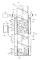
- the guide cylinder 118 is formed in a cylindrical shape, and guides the granular material conveyed by the auger 119 from the hopper 17 to the storage bag S.
- the auger 119 includes a rotating shaft 121 that rotates while being positioned in the guide tube 118, and a blade 122 that is provided on the rotating shaft 121 and rotates in the guide tube 118 by the rotation of the rotating shaft 121 to convey the granular material. Is formed.
- the rotating shaft 121 is rotatably supported by the hopper 17 and the cover 20. The rotating shaft 121 passes through the cover 20 and the hopper 17 and extends to the vicinity of the powder outlet 118a of the guide tube 118.
- a nitrogen supply path (gas guide path) for guiding the nitrogen gas (inert gas) supplied by the nitrogen gas supply device (gas supply unit) 27 from the upper end of the rotary shaft 121 to the vicinity of the lower end of the rotary shaft 121. ) 123 is formed.
- nitrogen outlets (gas supply ports) 126 are formed radially with the nitrogen supply path 123 as the center, as shown in FIG.
- the nitrogen outlet 126 is configured so that nitrogen gas guided by the nitrogen supply path 123 is ejected and nitrogen gas is included in the powder.
- the head of the rotating shaft 121 is connected to a nitrogen gas supply device (supply unit) 27 that supplies nitrogen gas via a rotatable elbow 25 and a nitrogen supply pipe 24.
- an intermediate portion in the axial direction of the guide cylinder 118 has a non-hole portion 118 b in which no through hole is formed in the guide cylinder 118, facing the nitrogen outlet 126 of the nitrogen supply path 123.
- the non-hole portion 118b is a cylindrical non-leakage cylindrical portion (gas non-leakage portion) 131.
- the non-leakage cylindrical portion 131 is formed so as not to have a gap in order to prevent nitrogen gas from leaking to the outside.
- a protective cylinder 139 is provided on the outer periphery of the non-leakage cylindrical portion 131 to protect each pipe, which will be described later, disposed along the outer periphery of the non-leakage cylindrical portion 131.
- a plurality of nitrogen outlets 126 may be formed in the region of the non-leakage cylindrical portion 131 along the axial direction of the rotating shaft 121.
- the guide cylinder 118 bleeds the granular material conveyed by the auger 119 upstream of the non-leaky cylindrical portion 131 in the axial direction (the granular material conveying direction).
- Upper suction part) 132 The air vent 132 is separated from the upper porous portion 118c of the guide tube 118 in which a number of air vent holes (through holes) 135 are formed, a cylindrical filter 133 provided on the outer periphery of the upper porous portion 118c, and the filter.
- the cylindrical upper peripheral cylinder 134 provided on the guide cylinder 118 so as to cover the filter 133 is formed.
- the upper outer cylinder 134 is provided on the guide cylinder 118 by a ring-shaped upper lid 175 and a bottom lid 180.
- the air vent hole 135 guides the air contained in the granular material in the guide cylinder 118 to the outside.
- the filter 133 allows air contained in the granular material in the guide tube to flow to the outside through the air vent hole 135, and the granular material in the guide tube leaks to the outside from the air vent hole 135. It is designed to prevent this.
- the upper outer cylinder 134 is composed of a ring-shaped upper lid 175 provided at the upper end and a ring-shaped bottom lid 180 provided at the lower end to form an upper negative pressure chamber 136 for extracting air from the guide cylinder 118. ing.
- the upper porous portion 118c in which the air vent hole 135 of the guide cylinder 118 is formed is weak in strength. For this reason, the upper outer cylinder 134 also serves to reinforce the guide cylinder 118.
- FIG. 13B is a diagram showing the positional relationship between the guide tube 118, the filter 133, and the upper outer peripheral tube 134.
- a reinforcing cylinder having a plurality of holes is provided on the outer periphery of the filter 133, similar to the reinforcement cylinder 71 shown in FIG. 4 of the first embodiment. Also good.
- An air vent elbow 137 that connects the upper negative pressure chamber 136 and the air / gas suction device 79 is provided in the air passage hole 138 formed in the upper lid 175 of the upper negative pressure chamber 136. As shown in FIGS. 11 and 12, two air vent elbows 137 are provided at intervals of 180 degrees.
- the guide cylinder 118 is arranged on the downstream side in the granular material transport direction from the non-leakage cylindrical portion 131 and the residual air remaining in the granular material without being sucked by the air vent 132.
- 131 has a nitrogen suction part (lower suction part) 140 for sucking the nitrogen gas filled in the granular material.
- the nitrogen suction part 140 includes a lower porous portion 118d of the guide cylinder 118 in which a large number of nitrogen suction holes (through holes) 145 are formed, and a cylindrical filter 143 provided on the outer periphery of the lower porous portion 118d.
- the lower outer peripheral tube 144 is formed of a cylindrical lower outer peripheral tube 144 or the like provided on the guide tube 118 so as to cover the filter 143 away from the filter.
- the lower outer peripheral tube 144 is provided on the guide tube 118 by a ring-shaped head cover 185 and a lower cover 176.
- the nitrogen suction hole 145 guides the residual air and nitrogen gas contained in the powder body in the guide cylinder 118 to the outside.
- the filter 143 allows residual air and nitrogen gas to flow to the outside through the nitrogen suction hole 145, and prevents the granular material in the guide tube from leaking to the outside from the nitrogen suction hole 145. ing.
- the lower outer cylinder 144 is composed of a ring-shaped head lid 185 provided at the upper end and a ring-shaped lower lid 176 provided at the lower end.
- the lower outer cylinder 144 is used to remove the residual air and nitrogen gas from the guide cylinder 118.
- a pressure chamber 146 is formed.
- the lower porous portion 118d in which the nitrogen suction hole 145 of the guide cylinder 118 is formed is weak in strength. For this reason, the lower outer peripheral tube 144 also serves to reinforce the guide tube 118.
- FIG. 14B is a diagram showing the positional relationship between the guide cylinder 118, the filter 143, and the lower outer peripheral cylinder 144.
- a reinforcing cylinder having a plurality of holes is provided on the outer periphery of the filter 133, similar to the reinforcing cylinder 71 shown in FIG. 4 of the first embodiment. Also good.
- a lower end of a nitrogen suction pipe 141 that connects the lower negative pressure chamber 146 and the air / gas suction device 79 is provided in the air passage hole 148 formed in the head cover 185 of the lower negative pressure chamber 146.
- the upper end of the nitrogen suction pipe 141 passes through the upper lid 175 and is connected to the air / gas suction device 79 by a nitrogen suction elbow 142.
- the air vent elbows 137 are also provided at intervals of 180 degrees as shown in FIGS.
- the granular material supply apparatus 111 of the second embodiment also has a nitrogen lower supply pipe 51 and a nitrogen upper supply pipe 61, as shown in FIGS. And two are provided. Description of this part is omitted.
- elbows 52, 137, 62, 142, 52, 137, 62, 142 are provided at equal intervals on the upper lid 175 in the circular direction.
- the upper outer peripheral cylinder 134, the protective cylinder 139, and the lower outer peripheral cylinder 144 described above may be a single integrated cylindrical member.
- the granular material supply device 111 and the storage bag K are relatively movable, and when at least one of them is moved up and down, the granular material discharge port 118 a of the guide tube 118 stores the granular material. Enter bag K. Then, the nitrogen gas supply device 27, the air / gas suction device 79, and a motor (not shown) for rotating the auger are started.
- the nitrogen gas N 2 is ejected.
- the gas outlet 51a is the lower end of the nitrogen lower supply pipe 51, and nitrogen gas supplied from the nitrogen gas supply device through the nitrogen lower supply elbow 52 and the nitrogen lower supply pipe 51 is ejected.
- the inside of the upper negative pressure chamber 136 of the air vent 132 is at a pressure lower than the atmospheric pressure (negative pressure) by the start of the air / gas suction device 79.
- the air contained in the powder that has reached the air vent portion 132 passes through the air vent hole 135 and the filter 133 and is sucked into the negative pressure chamber 136.
- the air passes through the passage hole 138 and the air vent elbow 137 and is sucked into the air / gas suction device 79.
- the powder passing through the air vent 132 is subjected to air venting (deaeration) of the air contained in the powder.
- the filter 133 is not easily clogged with powder particles.
- non-leakage cylindrical portion 131 nitrogen gas supplied by the nitrogen gas supply device 27 passes through the nitrogen supply pipe 24 (FIG. 10), the elbow 25, and the nitrogen supply path 123 (FIG. 14), and the nitrogen outlet 126. Has been ejected from. For this reason, nitrogen gas spreads over the granular material that has reached the inside of the non-leaky cylindrical portion 131.
- the non-leakage cylindrical portion 131 is in a slightly negative pressure state due to air bleeding. For this reason, it is easy for the nitrogen gas to reach the granular material. Further, since the nitrogen gas is ejected radially from the nitrogen outlet 126 of the rotating shaft 121 at the center of the granular material, it is spread over the granular material. Furthermore, since the non-leakage cylindrical portion 131 is formed so as not to have a gap, the nitrogen gas is filled (filled) so as to be pushed into the granular material.
- the nitrogen jet outlet 126 is located in the center of the axial direction (powder particle conveyance direction) of the non-leakage cylindrical part 131, multiple pieces may be formed in the thrust direction of the rotating shaft 121.
- the nitrogen outlet 126 is formed too close to the air vent 132 and the nitrogen suction portion 140, the nitrogen gas is sucked and discharged from the air vent 132 and the nitrogen suction portion 140. Cannot be used effectively. Therefore, by using the suction of the nitrogen gas to the air vent 132 and the nitrogen suction part 140, the nitrogen outlet 126 is provided at a position where the nitrogen gas reaches the granular material located in the non-leakage cylindrical part 131. Preferably formed.
- the granular material filled with nitrogen gas in the non-leakage cylindrical portion 131 is sent to the nitrogen suction portion 140.
- the powder sent to the nitrogen suction part 140 is sucked with nitrogen gas to ensure that the nitrogen gas filled in the non-leakage cylindrical part 131 is spread over the powder by the air / gas suction device 79.
- the Nitrogen gas passes through the nitrogen suction hole 145 and the filter 143 and is sucked into the negative pressure chamber 146, passes through the nitrogen suction pipe 141 and the nitrogen suction elbow 142, and is sucked into the air / gas suction device 79. The At this time, air remaining in the granular material is also sucked.
- the nitrogen suction part 140 does not extract the nitrogen gas contained in the granular material, but the nitrogen gas filled from the center of the granular material in the non-leakage cylindrical part 131 is removed from the outer periphery of the granular material (guide cylinder). 118 is provided to suck nitrogen gas from the inner periphery) and spread the nitrogen gas to the granular material. For this reason, nitrogen gas has spread throughout the granular material passing through the nitrogen suction part 140. Note that the filter 143 is not easily clogged with powder particles.
- the powder particles in which the nitrogen gas has spread are supplied from the powder particle discharge port 118a of the guide tube 118 to the storage bag K filled with nitrogen gas.
- the granular material P when the granular material P is substantially filled in the storage bag, it is located at the portion where the granular material discharge port 118a of the guide cylinder 118 is formed.
- nitrogen gas N 2 is ejected from the gas ejection port 61a.
- the gas outlet 61a is bent in an L shape. For this reason, it is rare that nitrogen gas hits a granular material and the granular material soars.
- the powder supply device 111 draws air contained in the powder, fills the powder with nitrogen gas, spreads the nitrogen gas into the powder, and then is filled with nitrogen gas.
- the granular material is supplied to the storage bag, and the upper portion of the storage bag is filled with nitrogen gas to close the storage bag.
- the granular material supply apparatus 111 can fill the granular material with an inert gas, prevent the granular material from being altered and solidified, and improve the quality of the packed granular material for a long period of time. Can be kept constant.
- the granular material supply apparatus 111 of 2nd Embodiment is also the same as the granular material supply apparatus 11 of 1st Embodiment by the at least one nitrogen lower supply pipe 51 in the two nitrogen lower supply pipes 51.
- the air in the storage bag may be sucked.
- the granular material supply device 111 is configured to extract air from the granular material by the air vent 132 while conveying the granular material by the auger 119 in the guide tube, thereby preventing the non-leaky cylindrical portion. 131.
- Nitrogen gas is contained in the granular material from the nitrogen outlet 126, and the residual air and nitrogen gas contained in the granular material are sucked in by the air vent 132, so the granular material is filled with an inert gas. It is possible to extend the quality assurance period of the granular material.
- the granular material supply apparatus is capable of supplying the granular material, and in particular, oxidized, denatured, solidified, such as wheat flour, skim milk powder, and toner containing a magnetic material for a copying machine. It is ideal for use in supplying easy-to-use powders.
Landscapes
- Engineering & Computer Science (AREA)
- Mechanical Engineering (AREA)
- Chemical & Material Sciences (AREA)
- Dispersion Chemistry (AREA)
- Supply Of Fluid Materials To The Packaging Location (AREA)
- Filling Or Emptying Of Bunkers, Hoppers, And Tanks (AREA)
- Basic Packing Technique (AREA)
Abstract
La présente invention concerne un dispositif d'alimentation en matériau granulaire (11) comportant les éléments suivants : un cylindre de guidage (18) dans lequel ont été pratiqués une pluralité de trous d'aspiration de gaz (28) destinés à guider un gaz interne vers l'extérieur, et qui guide un matériau granulaire ; un filtre (29) prévu dans la partie dans laquelle sont formés les trous d'aspiration de gaz du cylindre de guidage, et conçu pour laisser le gaz se trouvant à l'intérieur du cylindre de guidage s'échapper à l'extérieur à travers les trous d'aspiration de gaz, et conçu pour prévenir toute fuite vers l'extérieur ; un dispositif d'alimentation en azote gazeux (27) ; un arbre tournant (21) destiné à tourner à l'intérieur du cylindre de guidage ; et une pale (22) prévue sur l'arbre tournant, la pale tournant dans le cylindre de guidage grâce à la rotation de l'arbre tournant et transportant le matériau granulaire. L'arbre tournant est pourvu des éléments suivants : une vis sans fin (19) dans laquelle sont formés un canal d'alimentation en azote gazeux (23) destiné à guider le gaz inerte fourni par le dispositif d'alimentation en azote gazeux, et un orifice de distribution de gaz (26) à travers lequel le gaz inerte guidé par le canal d'alimentation en azote gazeux est distribué et incorporé ensuite au matériau granulaire ; et un dispositif d'aspiration d'air et de gaz (79) destiné à aspirer le gaz se trouvant à l'intérieur du cylindre de guidage vers l'extérieur du cylindre de guidage.
Priority Applications (2)
| Application Number | Priority Date | Filing Date | Title |
|---|---|---|---|
| EP12838439.3A EP2765099A4 (fr) | 2011-10-03 | 2012-10-03 | Dispositif d'alimentation en matériau granulaire |
| US14/349,158 US20140238536A1 (en) | 2011-10-03 | 2012-10-03 | Powder or granular material feeding apparatus |
Applications Claiming Priority (2)
| Application Number | Priority Date | Filing Date | Title |
|---|---|---|---|
| JP2011-219305 | 2011-10-03 | ||
| JP2011219305 | 2011-10-03 |
Publications (1)
| Publication Number | Publication Date |
|---|---|
| WO2013051621A1 true WO2013051621A1 (fr) | 2013-04-11 |
Family
ID=48043775
Family Applications (1)
| Application Number | Title | Priority Date | Filing Date |
|---|---|---|---|
| PCT/JP2012/075686 Ceased WO2013051621A1 (fr) | 2011-10-03 | 2012-10-03 | Dispositif d'alimentation en matériau granulaire |
Country Status (4)
| Country | Link |
|---|---|
| US (1) | US20140238536A1 (fr) |
| EP (1) | EP2765099A4 (fr) |
| JP (1) | JP6021570B2 (fr) |
| WO (1) | WO2013051621A1 (fr) |
Families Citing this family (23)
| Publication number | Priority date | Publication date | Assignee | Title |
|---|---|---|---|---|
| CA2853964A1 (fr) * | 2011-11-01 | 2013-05-10 | Altria Client Services Inc. | Appareil et procede permettant d'emballer un produit en vrac |
| JP6258732B2 (ja) * | 2014-03-14 | 2018-01-10 | 津田 博之 | 粉粒体供給装置 |
| JP6258731B2 (ja) * | 2014-03-14 | 2018-01-10 | 津田 博之 | 粉粒体搬送装置と粉粒体供給装置 |
| JP2016077948A (ja) * | 2014-10-14 | 2016-05-16 | 熊倉 勝 | 極小物質回収装置と粉粒体供給システム |
| CN104843207A (zh) * | 2015-05-15 | 2015-08-19 | 中山伙伴自动化机械有限公司 | 一种多列粉剂计量装置 |
| EP3150072B1 (fr) * | 2015-09-29 | 2019-05-15 | Albert Handtmann Maschinenfabrik GmbH & Co. KG | Machine de remplissage et procédé de mesure de niveau de remplissage à l'aide d'un capteur radar en particulier pour la fabrication de saucisses |
| FI11671U1 (fi) * | 2016-04-13 | 2017-05-24 | Prometec Tools Oy | Näytteenottolaite |
| US9845167B1 (en) * | 2016-09-01 | 2017-12-19 | Multiply Labs Inc. | Dispensing system |
| IT201600091025A1 (it) * | 2016-09-08 | 2018-03-08 | Ica Spa | Sistema e metodo per il confezionamento di polveri |
| CA3035487C (fr) * | 2016-09-08 | 2021-04-27 | Ica Spa | Systeme et procede d'emballage de poudres |
| IT201600122873A1 (it) * | 2016-12-02 | 2018-06-02 | Ica Spa | Sistema di dosatura e taglio per polveri compattate |
| CN208746295U (zh) * | 2017-02-14 | 2019-04-16 | 利乐拉瓦尔集团及财务有限公司 | 用于用内含物填充包装容器的填充管道和填充系统 |
| CN107310802A (zh) * | 2017-07-25 | 2017-11-03 | 天津翔盛新材料有限公司 | 一种绞龙式粉末涂料冷却装置 |
| JP7441480B2 (ja) * | 2018-04-27 | 2024-03-01 | 有限会社鎌倉エンジニアリング | 不活性気体混入装置と粉粒体供給装置 |
| US11091283B2 (en) * | 2018-05-01 | 2021-08-17 | David Nowaczyk | Apparatus and method for flushing a residual gas from a flow of granular product |
| CN109051039A (zh) * | 2018-08-31 | 2018-12-21 | 上海和创船舶工程有限公司 | 一种船载粉粒料打包充氮系统及其打包充氮方法 |
| JP6831143B1 (ja) * | 2020-06-08 | 2021-02-17 | テクニカエンジニアリング株式会社 | 不活性気体混入装置 |
| JP6750919B1 (ja) * | 2020-06-08 | 2020-09-02 | テクニカエンジニアリング株式会社 | 不活性気体供給装置と粉粒体供給装置 |
| CN111661373A (zh) * | 2020-07-27 | 2020-09-15 | 河津市炬华铝业有限公司 | 一种粉末包装用包装机 |
| CN113232917A (zh) * | 2021-05-26 | 2021-08-10 | 湖南盛东生物科技有限公司 | 一种饲料酶制剂粉料的灌装装置及灌装方法 |
| WO2023139114A1 (fr) * | 2022-01-19 | 2023-07-27 | Capsugel Belgium Nv | Dispositif de dosage d'un matériau particulaire solide |
| CN114789821B (zh) * | 2022-04-15 | 2023-10-27 | 中盐安徽红四方股份有限公司 | 糊树脂包装机 |
| US20250325450A1 (en) * | 2022-12-21 | 2025-10-23 | Qualicaps Co., Ltd. | Capsule filling apparatus |
Citations (8)
| Publication number | Priority date | Publication date | Assignee | Title |
|---|---|---|---|---|
| JPS5842507A (ja) * | 1981-09-02 | 1983-03-12 | Ishikawajima Harima Heavy Ind Co Ltd | 石炭サイロ |
| JPH05127527A (ja) * | 1991-11-08 | 1993-05-25 | Fujitsu Ltd | トナー保存方法、トナーカートリツジ、その製造方法及び現像器 |
| JPH09110135A (ja) * | 1995-10-13 | 1997-04-28 | Takeda Chem Ind Ltd | 固形物の螺旋搬送装置 |
| JPH1095405A (ja) * | 1996-09-20 | 1998-04-14 | Koichi Tosaka | 圧送置換密封法 |
| JP2006341449A (ja) * | 2005-06-08 | 2006-12-21 | Mitsubishi Engineering Plastics Corp | 粉体原料の供給装置および供給方法 |
| JP2007290735A (ja) * | 2006-04-24 | 2007-11-08 | Orihiro Engineering Co Ltd | ガス置換を行う包装袋の製造方法および縦型包装機 |
| JP2011073715A (ja) * | 2009-09-30 | 2011-04-14 | Daiki Shoji Kk | 不活性ガス置換充填包装機 |
| JP2011084311A (ja) | 2009-10-16 | 2011-04-28 | Kamacho Scale Co Ltd | 粉体脱気充填機 |
Family Cites Families (13)
| Publication number | Priority date | Publication date | Assignee | Title |
|---|---|---|---|---|
| US3456422A (en) * | 1967-07-19 | 1969-07-22 | Packaging Frontiers Inc | Packaging apparatus |
| US3580419A (en) * | 1968-04-02 | 1971-05-25 | Carter Eng Co | Method and apparatus for feeding and compacting finely divided particulate material |
| US3984320A (en) * | 1975-02-24 | 1976-10-05 | Barefoot Bernard B | Vacuum filter leg for clarifying vessel |
| JPS56142113A (en) * | 1980-03-25 | 1981-11-06 | Kuniai Takasaki | Method and apparatus for filling gas into packing bag in packer |
| DE3444515A1 (de) * | 1984-12-06 | 1986-06-19 | Hans Dipl.-Chem. 8953 Obergünzburg Gabler | Verfahren zum fuellen von steifen behaeltnissen |
| JP3814090B2 (ja) * | 1999-02-23 | 2006-08-23 | 株式会社テクニカ | 粉粒体排出制御装置、及び粉粒体充填装置 |
| DE10221567B4 (de) * | 2002-05-15 | 2007-06-21 | Bmh Chronos Richardson Gmbh | Verfahren und Vorrichtung zum Befüllen eines Sackes mit Luftabsaugung |
| US6904737B2 (en) * | 2002-08-01 | 2005-06-14 | General Mills, Inc. | Dispensing apparatus and method of dispensing |
| JP4150555B2 (ja) * | 2002-09-02 | 2008-09-17 | 株式会社東京自働機械製作所 | 縦形粉粒体脱気充填装置 |
| JP4531743B2 (ja) * | 2006-12-26 | 2010-08-25 | 三菱化学エンジニアリング株式会社 | 粉粒体の脱気装置 |
| DE102008006558A1 (de) * | 2008-01-29 | 2009-07-30 | Linde Ag | Inertgasschleuse zur Befüllung eines Behälters mit Schüttgut |
| WO2010131063A1 (fr) * | 2009-05-15 | 2010-11-18 | Aroma System Srl | Dispositif de transport d'objets à espacement égal dans machine d'emballage |
| NL2003319C2 (nl) * | 2009-07-31 | 2011-02-02 | Bag Treat Holland B V | Inrichting voor het verpakken van stortgoed. |
-
2012
- 2012-10-03 WO PCT/JP2012/075686 patent/WO2013051621A1/fr not_active Ceased
- 2012-10-03 JP JP2012221614A patent/JP6021570B2/ja not_active Expired - Fee Related
- 2012-10-03 US US14/349,158 patent/US20140238536A1/en not_active Abandoned
- 2012-10-03 EP EP12838439.3A patent/EP2765099A4/fr not_active Withdrawn
Patent Citations (8)
| Publication number | Priority date | Publication date | Assignee | Title |
|---|---|---|---|---|
| JPS5842507A (ja) * | 1981-09-02 | 1983-03-12 | Ishikawajima Harima Heavy Ind Co Ltd | 石炭サイロ |
| JPH05127527A (ja) * | 1991-11-08 | 1993-05-25 | Fujitsu Ltd | トナー保存方法、トナーカートリツジ、その製造方法及び現像器 |
| JPH09110135A (ja) * | 1995-10-13 | 1997-04-28 | Takeda Chem Ind Ltd | 固形物の螺旋搬送装置 |
| JPH1095405A (ja) * | 1996-09-20 | 1998-04-14 | Koichi Tosaka | 圧送置換密封法 |
| JP2006341449A (ja) * | 2005-06-08 | 2006-12-21 | Mitsubishi Engineering Plastics Corp | 粉体原料の供給装置および供給方法 |
| JP2007290735A (ja) * | 2006-04-24 | 2007-11-08 | Orihiro Engineering Co Ltd | ガス置換を行う包装袋の製造方法および縦型包装機 |
| JP2011073715A (ja) * | 2009-09-30 | 2011-04-14 | Daiki Shoji Kk | 不活性ガス置換充填包装機 |
| JP2011084311A (ja) | 2009-10-16 | 2011-04-28 | Kamacho Scale Co Ltd | 粉体脱気充填機 |
Non-Patent Citations (1)
| Title |
|---|
| See also references of EP2765099A4 |
Also Published As
| Publication number | Publication date |
|---|---|
| JP2013252898A (ja) | 2013-12-19 |
| US20140238536A1 (en) | 2014-08-28 |
| EP2765099A4 (fr) | 2015-03-04 |
| JP6021570B2 (ja) | 2016-11-09 |
| EP2765099A1 (fr) | 2014-08-13 |
Similar Documents
| Publication | Publication Date | Title |
|---|---|---|
| JP6021570B2 (ja) | 粉粒体供給装置、及び収容容器に充填された粉粒体の製造方法 | |
| KR101521671B1 (ko) | 비드 공급장치 | |
| CN102729330A (zh) | 混砂装置 | |
| WO2013108427A1 (fr) | Dispositif de grenaillage | |
| CN105775790A (zh) | 一种定量送料器 | |
| CN114130102B (zh) | 一种真空转筒过滤系统 | |
| KR20220100680A (ko) | 분말을 건조할 수 있는 적층 제조 분말 공급용 모듈 | |
| JP5395487B2 (ja) | 遠心力鋳造方法及び遠心力鋳造装置及び鋳造管 | |
| JPH10180152A (ja) | 粉体塗装用粉体塗料供給機 | |
| JP2011084311A (ja) | 粉体脱気充填機 | |
| CN211618139U (zh) | 一种减少扬尘的下料装置 | |
| CN116750523B (zh) | 一种散装水泥装车机负压抑尘系统及抑尘方法 | |
| JP6258731B2 (ja) | 粉粒体搬送装置と粉粒体供給装置 | |
| CN116142703B (zh) | 螺旋输送装置及其清理方法 | |
| JP7582725B1 (ja) | 包装システム | |
| JP4781525B2 (ja) | 粉体固化材混合システム | |
| JP2008528801A (ja) | 少なくとも1種の粉末材料で容器を充填する方法およびその方法を実施するための装置 | |
| JP6258732B2 (ja) | 粉粒体供給装置 | |
| JP2004050415A (ja) | 射出装置 | |
| JP5611269B2 (ja) | 射出成形機および成形材料の供給方法 | |
| KR100583771B1 (ko) | 탈기수단을 갖춘 분입체 제품 공급장치 | |
| CN109351515B (zh) | 一种铸造流涂装置 | |
| JP2010214656A (ja) | 材料供給システム | |
| JP2002331548A (ja) | 射出装置 | |
| CN214732940U (zh) | 具有除尘功能的负压输送斗 |
Legal Events
| Date | Code | Title | Description |
|---|---|---|---|
| 121 | Ep: the epo has been informed by wipo that ep was designated in this application |
Ref document number: 12838439 Country of ref document: EP Kind code of ref document: A1 |
|
| WWE | Wipo information: entry into national phase |
Ref document number: 14349158 Country of ref document: US |
|
| NENP | Non-entry into the national phase |
Ref country code: DE |
|
| REEP | Request for entry into the european phase |
Ref document number: 2012838439 Country of ref document: EP |
|
| WWE | Wipo information: entry into national phase |
Ref document number: 2012838439 Country of ref document: EP |