WO2013051623A1 - Corps émetteur de lumière, dispositif d'éclairage et phare - Google Patents
Corps émetteur de lumière, dispositif d'éclairage et phare Download PDFInfo
- Publication number
- WO2013051623A1 WO2013051623A1 PCT/JP2012/075702 JP2012075702W WO2013051623A1 WO 2013051623 A1 WO2013051623 A1 WO 2013051623A1 JP 2012075702 W JP2012075702 W JP 2012075702W WO 2013051623 A1 WO2013051623 A1 WO 2013051623A1
- Authority
- WO
- WIPO (PCT)
- Prior art keywords
- light
- phosphor
- laser
- excitation
- emitted
- Prior art date
- Legal status (The legal status is an assumption and is not a legal conclusion. Google has not performed a legal analysis and makes no representation as to the accuracy of the status listed.)
- Ceased
Links
Images









Classifications
-
- C—CHEMISTRY; METALLURGY
- C09—DYES; PAINTS; POLISHES; NATURAL RESINS; ADHESIVES; COMPOSITIONS NOT OTHERWISE PROVIDED FOR; APPLICATIONS OF MATERIALS NOT OTHERWISE PROVIDED FOR
- C09K—MATERIALS FOR MISCELLANEOUS APPLICATIONS, NOT PROVIDED FOR ELSEWHERE
- C09K11/00—Luminescent materials, e.g. electroluminescent or chemiluminescent
- C09K11/08—Luminescent materials, e.g. electroluminescent or chemiluminescent containing inorganic luminescent materials
- C09K11/0883—Arsenides; Nitrides; Phosphides
-
- C—CHEMISTRY; METALLURGY
- C09—DYES; PAINTS; POLISHES; NATURAL RESINS; ADHESIVES; COMPOSITIONS NOT OTHERWISE PROVIDED FOR; APPLICATIONS OF MATERIALS NOT OTHERWISE PROVIDED FOR
- C09K—MATERIALS FOR MISCELLANEOUS APPLICATIONS, NOT PROVIDED FOR ELSEWHERE
- C09K11/00—Luminescent materials, e.g. electroluminescent or chemiluminescent
- C09K11/08—Luminescent materials, e.g. electroluminescent or chemiluminescent containing inorganic luminescent materials
- C09K11/77—Luminescent materials, e.g. electroluminescent or chemiluminescent containing inorganic luminescent materials containing rare earth metals
- C09K11/7715—Luminescent materials, e.g. electroluminescent or chemiluminescent containing inorganic luminescent materials containing rare earth metals containing cerium
- C09K11/77218—Silicon Aluminium Nitrides or Silicon Aluminium Oxynitrides
-
- C—CHEMISTRY; METALLURGY
- C09—DYES; PAINTS; POLISHES; NATURAL RESINS; ADHESIVES; COMPOSITIONS NOT OTHERWISE PROVIDED FOR; APPLICATIONS OF MATERIALS NOT OTHERWISE PROVIDED FOR
- C09K—MATERIALS FOR MISCELLANEOUS APPLICATIONS, NOT PROVIDED FOR ELSEWHERE
- C09K11/00—Luminescent materials, e.g. electroluminescent or chemiluminescent
- C09K11/08—Luminescent materials, e.g. electroluminescent or chemiluminescent containing inorganic luminescent materials
- C09K11/77—Luminescent materials, e.g. electroluminescent or chemiluminescent containing inorganic luminescent materials containing rare earth metals
- C09K11/7728—Luminescent materials, e.g. electroluminescent or chemiluminescent containing inorganic luminescent materials containing rare earth metals containing europium
- C09K11/7734—Aluminates
-
- C—CHEMISTRY; METALLURGY
- C09—DYES; PAINTS; POLISHES; NATURAL RESINS; ADHESIVES; COMPOSITIONS NOT OTHERWISE PROVIDED FOR; APPLICATIONS OF MATERIALS NOT OTHERWISE PROVIDED FOR
- C09K—MATERIALS FOR MISCELLANEOUS APPLICATIONS, NOT PROVIDED FOR ELSEWHERE
- C09K11/00—Luminescent materials, e.g. electroluminescent or chemiluminescent
- C09K11/08—Luminescent materials, e.g. electroluminescent or chemiluminescent containing inorganic luminescent materials
- C09K11/77—Luminescent materials, e.g. electroluminescent or chemiluminescent containing inorganic luminescent materials containing rare earth metals
- C09K11/7728—Luminescent materials, e.g. electroluminescent or chemiluminescent containing inorganic luminescent materials containing rare earth metals containing europium
- C09K11/77348—Silicon Aluminium Nitrides or Silicon Aluminium Oxynitrides
-
- C—CHEMISTRY; METALLURGY
- C09—DYES; PAINTS; POLISHES; NATURAL RESINS; ADHESIVES; COMPOSITIONS NOT OTHERWISE PROVIDED FOR; APPLICATIONS OF MATERIALS NOT OTHERWISE PROVIDED FOR
- C09K—MATERIALS FOR MISCELLANEOUS APPLICATIONS, NOT PROVIDED FOR ELSEWHERE
- C09K11/00—Luminescent materials, e.g. electroluminescent or chemiluminescent
- C09K11/08—Luminescent materials, e.g. electroluminescent or chemiluminescent containing inorganic luminescent materials
- C09K11/77—Luminescent materials, e.g. electroluminescent or chemiluminescent containing inorganic luminescent materials containing rare earth metals
- C09K11/7783—Luminescent materials, e.g. electroluminescent or chemiluminescent containing inorganic luminescent materials containing rare earth metals containing two or more rare earth metals one of which being europium
- C09K11/77928—Silicon Aluminium Nitrides or Silicon Aluminium Oxynitrides
-
- F—MECHANICAL ENGINEERING; LIGHTING; HEATING; WEAPONS; BLASTING
- F21—LIGHTING
- F21S—NON-PORTABLE LIGHTING DEVICES; SYSTEMS THEREOF; VEHICLE LIGHTING DEVICES SPECIALLY ADAPTED FOR VEHICLE EXTERIORS
- F21S41/00—Illuminating devices specially adapted for vehicle exteriors, e.g. headlamps
- F21S41/10—Illuminating devices specially adapted for vehicle exteriors, e.g. headlamps characterised by the light source
- F21S41/12—Illuminating devices specially adapted for vehicle exteriors, e.g. headlamps characterised by the light source characterised by the type of emitted light
-
- F—MECHANICAL ENGINEERING; LIGHTING; HEATING; WEAPONS; BLASTING
- F21—LIGHTING
- F21S—NON-PORTABLE LIGHTING DEVICES; SYSTEMS THEREOF; VEHICLE LIGHTING DEVICES SPECIALLY ADAPTED FOR VEHICLE EXTERIORS
- F21S41/00—Illuminating devices specially adapted for vehicle exteriors, e.g. headlamps
- F21S41/10—Illuminating devices specially adapted for vehicle exteriors, e.g. headlamps characterised by the light source
- F21S41/14—Illuminating devices specially adapted for vehicle exteriors, e.g. headlamps characterised by the light source characterised by the type of light source
-
- F—MECHANICAL ENGINEERING; LIGHTING; HEATING; WEAPONS; BLASTING
- F21—LIGHTING
- F21S—NON-PORTABLE LIGHTING DEVICES; SYSTEMS THEREOF; VEHICLE LIGHTING DEVICES SPECIALLY ADAPTED FOR VEHICLE EXTERIORS
- F21S41/00—Illuminating devices specially adapted for vehicle exteriors, e.g. headlamps
- F21S41/10—Illuminating devices specially adapted for vehicle exteriors, e.g. headlamps characterised by the light source
- F21S41/14—Illuminating devices specially adapted for vehicle exteriors, e.g. headlamps characterised by the light source characterised by the type of light source
- F21S41/16—Laser light sources
-
- F—MECHANICAL ENGINEERING; LIGHTING; HEATING; WEAPONS; BLASTING
- F21—LIGHTING
- F21S—NON-PORTABLE LIGHTING DEVICES; SYSTEMS THEREOF; VEHICLE LIGHTING DEVICES SPECIALLY ADAPTED FOR VEHICLE EXTERIORS
- F21S41/00—Illuminating devices specially adapted for vehicle exteriors, e.g. headlamps
- F21S41/10—Illuminating devices specially adapted for vehicle exteriors, e.g. headlamps characterised by the light source
- F21S41/14—Illuminating devices specially adapted for vehicle exteriors, e.g. headlamps characterised by the light source characterised by the type of light source
- F21S41/176—Light sources where the light is generated by photoluminescent material spaced from a primary light generating element
-
- F—MECHANICAL ENGINEERING; LIGHTING; HEATING; WEAPONS; BLASTING
- F21—LIGHTING
- F21S—NON-PORTABLE LIGHTING DEVICES; SYSTEMS THEREOF; VEHICLE LIGHTING DEVICES SPECIALLY ADAPTED FOR VEHICLE EXTERIORS
- F21S41/00—Illuminating devices specially adapted for vehicle exteriors, e.g. headlamps
- F21S41/10—Illuminating devices specially adapted for vehicle exteriors, e.g. headlamps characterised by the light source
- F21S41/19—Attachment of light sources or lamp holders
-
- F—MECHANICAL ENGINEERING; LIGHTING; HEATING; WEAPONS; BLASTING
- F21—LIGHTING
- F21S—NON-PORTABLE LIGHTING DEVICES; SYSTEMS THEREOF; VEHICLE LIGHTING DEVICES SPECIALLY ADAPTED FOR VEHICLE EXTERIORS
- F21S41/00—Illuminating devices specially adapted for vehicle exteriors, e.g. headlamps
- F21S41/20—Illuminating devices specially adapted for vehicle exteriors, e.g. headlamps characterised by refractors, transparent cover plates, light guides or filters
- F21S41/24—Light guides
-
- F—MECHANICAL ENGINEERING; LIGHTING; HEATING; WEAPONS; BLASTING
- F21—LIGHTING
- F21V—FUNCTIONAL FEATURES OR DETAILS OF LIGHTING DEVICES OR SYSTEMS THEREOF; STRUCTURAL COMBINATIONS OF LIGHTING DEVICES WITH OTHER ARTICLES, NOT OTHERWISE PROVIDED FOR
- F21V9/00—Elements for modifying spectral properties, polarisation or intensity of the light emitted, e.g. filters
- F21V9/14—Elements for modifying spectral properties, polarisation or intensity of the light emitted, e.g. filters for producing polarised light
-
- F—MECHANICAL ENGINEERING; LIGHTING; HEATING; WEAPONS; BLASTING
- F21—LIGHTING
- F21Y—INDEXING SCHEME ASSOCIATED WITH SUBCLASSES F21K, F21L, F21S and F21V, RELATING TO THE FORM OR THE KIND OF THE LIGHT SOURCES OR OF THE COLOUR OF THE LIGHT EMITTED
- F21Y2115/00—Light-generating elements of semiconductor light sources
- F21Y2115/10—Light-emitting diodes [LED]
-
- F—MECHANICAL ENGINEERING; LIGHTING; HEATING; WEAPONS; BLASTING
- F21—LIGHTING
- F21Y—INDEXING SCHEME ASSOCIATED WITH SUBCLASSES F21K, F21L, F21S and F21V, RELATING TO THE FORM OR THE KIND OF THE LIGHT SOURCES OR OF THE COLOUR OF THE LIGHT EMITTED
- F21Y2115/00—Light-generating elements of semiconductor light sources
- F21Y2115/30—Semiconductor lasers
Definitions
- the present invention relates to an illumination device that functions as a high-intensity light source and a headlamp that includes the illumination device.
- the present invention also relates to a light emitter capable of irradiating illumination light, a lighting device including the light emitter, and a headlamp including the lighting device.
- LEDs light emitting diodes
- LDs semiconductor lasers
- Patent Document 1 discloses such a light-emitting device.
- This light-emitting device uses a GaN-based semiconductor laser that emits laser light having a wavelength of 450 nm or less as an excitation light source, and combines a phosphor that emits fluorescence in the visible region when excited with the laser light.
- the phosphor is sufficiently excited by light having a short wavelength of 450 nm or less, such as blue light and ultraviolet light, so that high-luminance light emission can be obtained.
- a light source that emits white light by combining an excitation light source typified by a white LED and a phosphor has been developed.
- a pseudo white light source in which a blue LED and a yellow phosphor are combined was mainly used at the time of development.
- the yellow phosphor is modified to increase the emission intensity in the red region, or two types of phosphors, a green phosphor and a red phosphor, are used instead of the yellow phosphor. Attempts have been made to combine them.
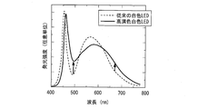
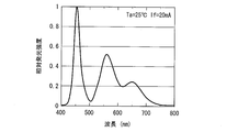
- FIG. 11 shows emission spectra of a conventional white LED and a high color rendering white LED.
- FIG. 12 shows an emission spectrum of a white LED in which a green phosphor and a red phosphor are combined (room temperature 25 ° C., forward current 20 mA).
- the high color rendering white LED increases the emission intensity in the red region and the green region by improving the yellow phosphor as compared with the conventional white LED. Further, as shown in FIG. 12, even in a white LED in which a green phosphor and a red phosphor are combined, the emission intensity in the red region and the green region is increased.
- FIG. 13 shows a visibility curve which is a characteristic of the visibility.
- the visibility in the vicinity of 650 nm, which is called red is considerably low.
- the visibility becomes lower as the wavelength becomes longer from there.
- each white LED As can be seen from the emission spectrum of each white LED shown in FIG. 11 and FIG. 12, the light emitted from each white LED has almost no visual sensitivity (cannot be felt by the eyes) of 700 nm or more. It contains a lot of light in the wavelength range. The light that cannot be felt by the eyes is simply a loss because visible light (excitation light) emitted from a blue LED that is an excitation light source is wavelength-converted by a phosphor and emitted as invisible light. Therefore, power corresponding to such a loss is wasted in the blue LED.
- Patent Document 2 discloses an example of a light emitter used in the lighting device as described above.
- a blue phosphor layer excited by excitation light in the ultraviolet region or blue-violet region, and a yellow phosphor excited by blue light generated from the blue phosphor A phosphor containing a layer and a red phosphor layer that is excited by excitation light in the wavelength region from the ultraviolet region to the blue-violet region is disclosed.
- Patent Document 3 discloses a polycrystal having both a property of transmitting light and a property of scattering light.
- Patent Document 4 as another example of a light emitter, a blue phosphor having an emission peak wavelength in a wavelength region of 400 nm or more and less than 500 nm, and a yellow phosphor having an emission peak wavelength in a wavelength region of 550 nm or more and less than 600 nm. And the combination is disclosed.
- Patent Document 5 discloses a first layer in which a first phosphor that converts light from a semiconductor light emitting element into blue light is dispersed, and a second layer that converts blue light into yellow or yellow-green light.
- a surface light source comprising a second layer in which the phosphor is dispersed is disclosed.
- Patent Document 6 discloses a laminate including a red phosphor layer, a yellow phosphor layer, a green phosphor layer, and a blue phosphor layer, which are sequentially formed in a convex curve shape on a transparent resin layer. Has been.
- the fluorescence spectrum of the phosphor has a characteristic that is broad to some extent, centered on the peak wavelength.
- the half-value width is 90 nm.
- red phosphors have a relatively sharp emission spectrum.
- examples of such a phosphor include phosphors having Mn 4+ or Eu 3+ as the emission center.
- a red phosphor having an emission center of Eu 3+ exhibits light emission based on a 4f 6 -4f 6 transition shielded by 5s 2 5p 6 electrons, and thus the emission color does not greatly depend on the host material.
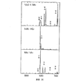
- FIG. 14 shows an emission spectrum of such a red light emitter. As shown in FIG. 14, the emission spectrum is linear even in the crystal.
- such a phosphor having a narrow emission spectrum width generally has a low transition probability and does not emit light at a single wavelength. For this reason, the visibility is sufficiently high and only a desired wavelength cannot be efficiently emitted.
- the above phosphor has a characteristic that the fluorescence lifetime is long (on the order of milliseconds). This characteristic that the fluorescence lifetime is long induces saturation of fluorescence emission when strongly excited, and thus is not suitable for a lighting device using a laser that is a typical strong excitation illumination as an excitation light source.
- the conventional technique has a problem that it is difficult to improve the light emission efficiency by suppressing the scattering efficiency while suppressing unnecessary absorption of the excitation light inside the light emitter.
- the phosphor disclosed in Patent Document 2 includes a red phosphor layer, but this red phosphor layer naturally has little effect of scattering the excitation light in order to absorb the excitation light.
- the present invention has been made in view of the above problems, and firstly has an object to provide a lighting device that has good color rendering (reproducibility) for red and can emit light with low power consumption. To do.
- a second object of the present invention is to provide a light emitter, an illuminating device, and a headlamp capable of improving the light emission efficiency by suppressing the unnecessary absorption of the excitation light inside the light emitter and improving the light emission efficiency.
- an illumination device includes a first light source (excitation light source) that oscillates excitation light with a blue-violet or blue wavelength and a second light source that oscillates laser light with a red wavelength.
- a light source including a phosphor that emits fluorescence when excited by the excitation light emitted from the first excitation light source, and a diffusion unit that diffuses the laser light emitted from the second light source. It is characterized by being.
- white light is obtained by mixing the light of the first light source (excitation light source), the fluorescence emitted from the light emitting unit, and the laser light of the second light source.
- the illumination light can include red light without essentially including light in a region having low or no visibility. .
- efficiency can be improved more compared with the conventional white LED. Therefore, it is possible to obtain an illumination device that has a good color rendering property (reproducibility) for red and can emit light with low power consumption.
- the light emitter of the present invention receives the excitation light having the wavelength in the first wavelength region and has the fluorescence having the emission peak wavelength in the second wavelength region longer than the first wavelength region.
- a phosphor that includes at least a first phosphor that generates light and a second phosphor that is excited by fluorescence, wherein the first phosphor has a valley of an absorption spectrum in the first wavelength region.
- the phosphors other than the first phosphor have an absorption spectrum valley in the first wavelength region.
- the first phosphor does not have an absorption spectrum valley in the first wavelength region, and phosphors other than the first phosphor exist in the first wavelength region. Has a valley in the absorption spectrum. That is, the second phosphor or the third and subsequent phosphors (hereinafter simply referred to as “second and subsequent phosphors”) have a higher probability of not absorbing the excitation light than the first phosphor, and scatter the excitation light. Or the probability of spreading is high. Therefore, unnecessary absorption of the excitation light is suppressed inside the luminescent material, and if the second and subsequent phosphors are not present, the excitation light that may have been emitted to the outside is directly reflected by the second and subsequent phosphors. Since it is scattered or diffused, the scattering efficiency of the excitation light inside the light emitter is improved.
- the second phosphor is excited by light generated from the first phosphor.
- the second phosphor can also emit fluorescence. Therefore, the fluorescence of the first phosphor and the fluorescence of the second phosphor can be emitted to the outside as illumination light.
- the light emission efficiency of the light emitter as a whole is improved.
- the light emitter of the present invention adjusts the color (chromaticity) and color rendering of the illumination light by adjusting the weight ratio of the first phosphor to the second phosphor. be able to.
- the illuminating device according to the present invention which is configured as described above, has an effect that it has a good color rendering property (reproducibility) for red and can emit light with low power consumption.
- the first phosphor does not have an absorption spectrum valley in the first wavelength region, and phosphors other than the first phosphor , Having a valley of an absorption spectrum in the first wavelength region.
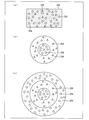
- FIG. 4 is a diagram schematically showing an example of the composition of a light emitter according to another embodiment of the present invention, and (a) to (c) show examples of the composition of the light emitter, respectively.
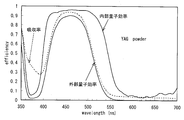
- It is a graph showing the relationship between the wavelength of the excitation light of YAG: Ce fluorescent substance, and efficiency (absorption rate, internal quantum efficiency, or external quantum efficiency).
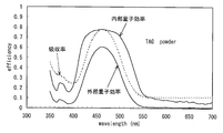
- It is a graph showing the relationship between the wavelength of the excitation light of a TAG: Ce phosphor and efficiency (absorption rate, internal quantum efficiency or external quantum efficiency).
- JEM phase a graph showing the relationship between the wavelength of the excitation light and the absorptance of the Ce phosphor.
- the illumination device of the present invention a headlamp (headlight) for an automobile will be described as an example.
- the lighting device of the present invention may be realized as a headlamp of a vehicle other than an automobile or a moving body (human, ship, aircraft, submarine, rocket, etc.), or may be realized as another lighting device.
- the other lighting device include a searchlight, a projector, a home lighting device, an indoor lighting device, and an outdoor lighting device.
- the headlamp may satisfy the light distribution characteristic standard of the traveling headlamp (high beam), or may satisfy the light distribution characteristic standard of the passing headlamp (low beam).
- FIG. 1 is a longitudinal sectional view showing a schematic configuration of the headlamp 1.
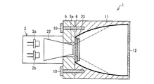
- a headlamp 1 as a first headlamp includes a light source unit 2 (light source), a fixing member 5, a translucent substrate 6, a screw 10, a reflecting mirror 11, a lens 12, and a light guide member 22. And a light emitting unit 23.
- the laser light emitted from the semiconductor lasers 2 a and 2 b of the light source unit 2 is guided to the light emitting unit 23 by the light guide member 22.
- the light emitting unit 23 is excited by the laser light emitted from the semiconductor laser 2a to emit fluorescence, and among the laser light, the laser light that has not contributed to the excitation of the light emitting unit 23 is diffused by the light emitting unit 23 having a diffusion function. Is done. Further, a part of the laser light emitted from the semiconductor laser 2a passes through the light emitting unit 23 as it is. On the other hand, the laser beam emitted from the semiconductor laser 2 b is diffused by the light emitting unit 23.
- the fluorescence emitted from the light emitting part 23, the laser light of the semiconductor laser 2a diffused by the light emitting part 23, the fluorescence emitted by the light emitting part 23, and the laser of the semiconductor laser 2b diffused by the light emitting part 23 The light is mixed and the headlamp 21 emits white light.
- the light source unit 2 is a laser light source device, and houses two semiconductor lasers (excitation light sources) 2a and 2b in a housing.
- the semiconductor lasers 2a and 2b are light-emitting elements that function as light sources that emit laser light, and are arranged at a predetermined interval. Since the conventional fixing method and wiring method can be used for the fixing method and wiring method of the semiconductor lasers 2a and 2b, description thereof is omitted here.
- the light source may be another laser light source or an LED.
- the light emitting unit 7 can be irradiated with laser light having high output and high coherency, so that the light emitting unit 7 can be made small and the headlamp 1 having high brightness can be obtained.
- the semiconductor laser 2a (first light source (excitation light source)) has one light emitting point per chip and oscillates laser light having a wavelength in a blue region or a blue-violet region.
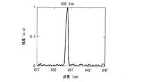
- the semiconductor laser 2b (second light source) has one light emitting point per chip, and oscillates laser light having a wavelength in the red region (wavelength near 635 nm).
- the semiconductor lasers 2a and 2b are enclosed in a metal package (stem) having a diameter of 9 mm, 5.6 mm, 3.8 mm or the like, but are preferably enclosed in a package having a smaller thermal resistance.
- the semiconductor lasers 2a and 2b may have a plurality of light emitting points on one chip.
- FIG. 1 shows one semiconductor laser 2a and 2b one by one, but a plurality of semiconductor lasers 2a and 2b may be provided instead of one by one. Thereby, high output excitation light can be obtained.
- FIG. 21C is a circuit diagram showing a configuration of an equivalent circuit of the semiconductor lasers 2a and 2b (similar to a semiconductor laser 202 described later), and FIG. 21D is a basic structure of the semiconductor lasers 2a and 2b.
- FIG. 21C is a circuit diagram showing a configuration of an equivalent circuit of the semiconductor lasers 2a and 2b (similar to a semiconductor laser 202 described later)
- FIG. 21D is a basic structure of the semiconductor lasers 2a and 2b.
- the semiconductor lasers 2a and 2b have a configuration in which a cathode electrode 111, a substrate 112, a cladding layer 113, an active layer 114, a cladding layer 115, and an anode electrode 116 are stacked in this order.
- the substrate 112 is a semiconductor substrate, and it is preferable to use GaN, sapphire, or SiC in order to obtain blue to ultraviolet laser light for exciting the phosphor as in the present application, and to obtain red laser light.
- Is preferably GaAs.
- any one of a group IV semiconductor, a group III-V compound semiconductor, a group II-VI compound semiconductor, an oxide insulator, or a nitride insulator is used as an example of a substrate for a semiconductor laser.
- the group IV semiconductor include Si, Ge, and SiC.
- III-V compound semiconductors include GaAs, GaP, InP, AlAs, GaN, InN, InSb, GaSb, and AlN.
- Examples of II-VI compound semiconductors include ZnTe, ZeSe, ZnS, and ZnO. Can be mentioned. Furthermore, examples of the oxide insulator include ZnO, Al 2 O 3 , SiO 2 , TiO 2 , CrO 2 , and CeO 2, and examples of the nitride insulator include SiN.
- the anode electrode 116 is an electrode for injecting current into the active layer 114 through the cladding layer 115.
- the cathode electrode 111 is an electrode for injecting current from the lower part of the substrate 112 to the active layer 114 through the cladding layer 113.
- the current is injected by applying a forward bias from the anode electrode 116 to the cathode electrode 111.
- the active layer 114 is sandwiched between the clad layer 113 and the clad layer 115.
- a mixed crystal semiconductor made of AlInGaN is used to obtain blue to ultraviolet laser light
- a mixed crystal semiconductor made of AlGaInP is used to obtain red laser light. Is used.
- a mixed crystal semiconductor having a main composition of Al, Ga, In, As, P, N, and Sb is used as an active layer and a cladding layer of a semiconductor laser. Therefore, the active layer 114 and the cladding layers 113 and 115 may have such a configuration.
- the active layer 114 and the cladding layers 113 and 115 may be made of a II-VI group compound semiconductor such as Zn, Mg, S, Se, Te, ZnO.
- the active layer 114 is a region where light emission occurs due to the injected current. In the active layer 114, the emitted light is confined in the active layer 114 due to the difference in refractive index between the clad layer 115 and the clad layer 113.
- the active layer 114 is provided with a front side cleaved surface 117 and a back side cleaved surface 118 provided to face each other in order to confine light amplified by stimulated emission.
- the front side cleavage surface 117 and the back side cleavage surface 118 serve as mirrors.
- part of the light amplified by stimulated emission is separated from the front side cleaved surface 117 and the back side cleaved surface 118 (in this embodiment, the front side cleaved surface 117 for convenience.
- the active layer 114 may form a multilayer quantum well structure.
- a reflective film (not shown) for laser oscillation is formed on the back side cleaved surface 118 opposite to the front side cleaved surface 117.
- the laser light L0 is irradiated from the light emitting point 116 from the front-side cleaved surface 117, which is a low-reflectance end surface, for example. can do.
- the clad layers 113 and 115 may each be composed of either a III-V group compound semiconductor or a II-VI group compound semiconductor.
- Group III-V compound semiconductors include GaAs, GaP, InP, AlAs, GaN, InN, InSb, GaSb, and AlN.
- Group II-VI compound semiconductors include ZnTe, ZeSe, ZnS, and ZnO. It is done.
- a current can be injected into the active layer 114 by applying a forward bias to the anode electrode 116 and the cathode electrode 111.
- Each semiconductor layer such as the cladding layers 113 and 115 and the active layer 114 can be formed by using a general film forming method.
- film formation techniques include MOCVD (metal organic chemical vapor deposition), MBE (molecular beam epitaxy), CVD (chemical vapor deposition), laser ablation, and sputtering.
- MOCVD metal organic chemical vapor deposition
- MBE molecular beam epitaxy
- CVD chemical vapor deposition
- laser ablation laser ablation
- sputtering sputtering.
- Each metal layer can be formed using a general film forming method such as a vacuum deposition method, a plating method, a laser ablation method, or a sputtering method.
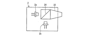
- FIG. 2 is a half sectional view showing another configuration of the light source unit 2.
- the light source unit 2 may be configured as shown in FIG.
- the light source unit 2 includes a half mirror 24.
- the half mirror 24 is disposed on the light incident surface side of the light guide member 22.
- the semiconductor laser 2 a is disposed on one light incident surface side of the two light incident surfaces of the half mirror 24.
- the semiconductor laser 2 b is disposed on the other light incident surface side of the half mirror 24.
- the light emitted from the semiconductor laser 2a and the light emitted from the semiconductor laser 2b are completely overlapped by the half mirror 24 and guided to the light guide member 22. Thereby, generation
- the light source unit 2 shown in FIG. 2 can be suitably used for the headlamp 1.
- the light guide member 22 is a member that guides the laser light oscillated by the semiconductor lasers 2 a and 2 b to the light emitting unit 23.
- the light guide member 22 includes an incident end (semiconductor lasers 2a and 2b side) that receives laser light emitted from the semiconductor lasers 2a and 2b, and an emission end (light emission) that emits laser light incident from the incident end. Part 23 side).
- the light guide member 22 has a surrounding structure surrounded by a light reflecting side surface that reflects the laser light incident on the incident end. Moreover, the light guide member 22 is formed so that the cross-sectional area of the exit end is smaller than the cross-sectional area of the entrance end. Specifically, the light guide member 22 has a quadrangular frustum shape as a whole, but may be formed in various shapes such as a polygonal frustum shape, a truncated cone shape, and an elliptic frustum shape.
- the light guide member 22 condenses the laser light incident on the incident end portion on the emission end portion having a cross-sectional area smaller than the cross-sectional area of the incident end portion, and then emits the light to the light emitting portion 23. Can do. For this reason, the light emission part 23 can be designed small.
- the light guide member 22 is formed of a transparent material such as BK (borosilicate crown) 7, quartz glass, acrylic resin, or the like.
- the laser light may be condensed on the light emitting unit 7 using an optical fiber or an optical lens instead of the light guide member 22.
- the fixing member 5 is a plate-like member for fixing the translucent substrate 6, and has a light guide hole 5 a penetrating through the central portion. In the light guide hole 5a, the light emission end portions of the light guide members 3 and 4 are arranged.
- the light source unit 2 is attached to the surface of the fixing member 5 on the light source unit 2 side so as to cover the light guide hole 5a. Further, the fixing member 5 is coupled to the reflecting mirror 11 by a screw 10.
- the material of the fixing member 5 is not particularly limited, but a metal such as iron or copper can be used.
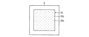
- FIG. 3 is a plan view showing the configuration of the light-transmitting substrate 6 and the light emitting unit 23 in the headlamp 1.
- the translucent substrate 6 is a plate-like member and has translucency for at least the laser beams having the oscillation wavelengths of the semiconductor lasers 2a and 2b.
- the light emitting portion 23 is bonded (adhered) to the surface on the lens 12 side with an adhesive.
- the translucent substrate 6 may have a curved portion instead of a flat plate shape, but at least a portion to which the light emitting portion 23 is bonded is a flat surface (plate shape) from the viewpoint of adhesion stability. preferable.
- the joining of the translucent substrate 6 and the light emitting part 23 is not limited to adhesion as described above, and may be, for example, fusion.
- As the adhesive so-called organic adhesives and glass paste adhesives are suitable, but not limited thereto.
- the translucent substrate 6 is thermally connected to the light emitting unit 23 (so that heat energy can be transferred) by joining the light emitting unit 23. Thereby, the heat generated in the light emitting unit 23 is dissipated from the light transmitting substrate 6 to the outside while fixing (holding) the light emitting unit 23 to the surface of the light transmitting substrate 6, thereby improving the cooling efficiency of the light emitting unit 23. Can be made.
- the translucent substrate 6 is made of Al 2 O 3 (sapphire).
- the material of the translucent substrate 6 is preferably magnesia (MgO), gallium nitride (GaN), or spinel (MgAl 2 O 4 ) in addition to sapphire (Al 2 O 3 ). This is because these materials have excellent thermal conductivity (for example, 20 W / mK or more) and translucency. If this point is not taken into consideration, the material is not limited to these materials, and may be glass (quartz), for example.
- the outer dimension of the translucent substrate 6 is larger than the outer dimension of the light emitting unit 23, but may be approximately the same as the outer dimension of the light emitting unit 23.
- the thickness of the translucent substrate 6 is preferably 30 ⁇ m or more and 1.0 mm or less, more preferably 0.2 mm or more, 1 in consideration of effectively dissipating heat generated in the light emitting portion 23. More preferably, it is 0.0 mm or less.
- the thickness of the translucent substrate 6 exceeds 1.0 mm, the ratio of the laser light irradiated to the light emitting unit 23 absorbed by the translucent substrate 6 is increased, but the heat dissipation effect is not so great. It does not improve, and the cost of the member also increases.
- the light emitting unit 23 is a member that receives the laser light emitted from the semiconductor laser 2a and emits fluorescence and diffuses the laser light emitted from the semiconductor lasers 2a and 2b, and is formed to form a rectangular parallelepiped. Moreover, the light emission part 23 is not limited to a rectangular parallelepiped, For example, you may form in a column shape.
- the light emitting portion 23 is formed by dispersing the phosphor 23b that emits the above fluorescence in the sealing material 23a.
- the sealing material 23a is made of the same material as that constituting the sealing material 7a.
- the phosphor 23b has an absorptance of 10% or less in the oscillation wavelength region (red light region) of the semiconductor laser 2b.
- a YAG: Ce phosphor As the phosphor 23b having an absorptance of 10% or less in the red light region, a YAG: Ce phosphor is suitable.
- a YAG: Ce phosphor has an absorptance of 1% or less in a wavelength region of 600 nm or more, and can only scatter and diffuse without absorbing red light.
- GAL phosphors (green phosphors), ⁇ -SiAlON: Eu phosphors (green phosphors) and Ca ⁇ -SiAlON: Ce phosphors (blue-green phosphors) described later also have an absorption rate of 10% or less in the red region. It is. Further, although there is room for improvement in the characteristics of a JEM phosphor (blue phosphor) described later, the absorptance in the red wavelength region can be reduced to 10% or less.
- the light emitting unit 23 since the light emitting unit 23 has a diffusing function, it utilizes a difference in refractive index between the sealing material 23a and the phosphor 23b. Specifically, the difference in refractive index between the sealing material 23a and the phosphor 23b is set so that the reflectance at the interface between the sealing material 23a and the phosphor 23b becomes a desired value. For this reason, the light emitting unit 23 is designed to have deposition (particularly thickness) that can sufficiently diffuse the laser light. Thereby, the phosphor 23b functions as a good scattering / diffusing material for blue laser light or blue-violet laser light.
- the light emission part 23 may be comprised so that it may have a spreading
- white light or pseudo white light used as illumination light can be realized by mixing three colors that satisfy the principle of color matching, or mixing two colors that satisfy a complementary color relationship. Based on this principle of color matching, in the headlamp 1, the color of the laser light emitted from the semiconductor laser 2 a, the color of the laser light emitted from the semiconductor laser 2 b, and the light emitted from the light emitting unit 23. White light is obtained by mixing the colors.
- a yellow phosphor or a green phosphor is used as the phosphor 23b.
- the yellow light emitting phosphor is a phosphor that emits fluorescence having a peak wavelength in a wavelength range of 560 nm to 590 nm (yellow region).
- the green phosphor is a phosphor that generates fluorescence having a peak wavelength in a wavelength range (green region) of 510 nm or more and 560 nm or less.
- the blue phosphor is a phosphor that generates fluorescence having a peak wavelength in a wavelength range (blue region) of 450 nm or more and 490 nm or less.
- the blue-green phosphor is a phosphor that emits fluorescence having a peak wavelength in a wavelength range of 490 nm to 510 nm (blue-green region).
- the laser light oscillated from the semiconductor laser 2a is irradiated onto the phosphor 23b included in the light emitting unit 23, so that electrons existing in the phosphor 23b are excited from a low energy state to a high energy state (excited state). Is done.
- the energy state of the electrons in the phosphor 23b changes to the original low energy state (between the energy state of the ground level or between the excited level and the ground level) after a certain time. Transition to a metastable energy state.
- the phosphors emit light when the electrons excited to the high energy state transition to the low energy state.
- the refractive index difference ⁇ n with respect to 23 is preferably 0.35 or less.
- the reflectance R can be 1% or less.
- the refractive index difference ⁇ n is 0.35 or less, it is preferable that the refractive index of the translucent substrate 6 is 1.65 or more and the refractive index of the light emitting part 23 is 2.0 or less.
- the light emitting unit 23 has a diffusion function as described above, but may not have a diffusion function. As such a light emission part, the light emission part 7 in the 2nd headlamp 21 shown in FIG. 4 can be provided. When the light emitting unit 7 is provided, the light emitting unit 7 does not have a diffusing function. Therefore, as will be described later, a diffusing unit 8 is separately required to provide the diffusing function.
- the reflecting mirror 11 is an optical member that forms a light bundle that travels within a predetermined solid angle by reflecting light emitted from the light emitting unit 7.
- the reflecting mirror 11 reflects the light from the light emitting unit 7 to form a light beam traveling forward of the headlamp 1.
- the reflecting mirror 11 has, for example, a reflecting surface having a curved surface shape (cup shape) on which a metal thin film is formed.
- the reflecting mirror 11 is not limited to a hemispherical mirror, and may be an elliptical mirror, a parabolic mirror, or a mirror having a partial curved surface thereof. In other words, the reflecting mirror 11 only needs to include at least a part of a curved surface formed by rotating a figure (ellipse, circle, parabola) about the rotation axis on the reflecting surface.
- the lens 12 is provided in the opening of the reflecting mirror 11 and seals the headlamp 1.
- the fluorescence emitted from the light emitting unit 7, the scattered light scattered by the diffusion units 8 and 9, or the fluorescence or scattered light reflected by the reflecting mirror 11 is emitted through the lens 12 to the front of the headlamp 1.
- the lens 12 may be a convex lens or a concave lens.
- the lens 12 does not necessarily have a lens function, and at least the fluorescence emitted from the light emitting unit 7, the scattered light scattered by the diffusion units 8 and 9, or the fluorescence or scattered light reflected by the reflecting mirror 11 is used. What is necessary is just to have translucency which permeate
- the diffusion function which the above-mentioned diffusion parts 8 and 9 have in the lens 12 may be provided.
- the diffusion units 8 and 9 are not necessary.
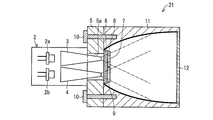
- FIG. 4 is a longitudinal sectional view showing a schematic configuration of the headlamp 21.
- headlamp 21 as the second headlamp, components having the same functions as the components in the above-described headlamp 1 are denoted by the same reference numerals, and description thereof is omitted.
- the headlamp 21 as the second headlamp includes a light source unit 2, light guide members 3 and 4, a fixing member 5, a translucent substrate 6, a light emitting unit 7, diffusion units 8 and 9, A screw 10, a reflecting mirror 11, and a lens 12 are provided.
- the laser light emitted from the semiconductor laser 2 a of the light source unit 2 is guided to the light emitting unit 7 and the diffusing unit 8 by the light guide member 3, and the laser light emitted from the semiconductor laser 2 b of the light source unit 2. Is guided to the diffusion part 9 by the light guide member 4. Further, the light emitting unit 7 is excited by the laser light emitted from the semiconductor laser 2 a to emit fluorescence, and the laser light is diffused by the diffusion unit 8. On the other hand, the laser light emitted from the semiconductor laser 2 b is diffused by the diffusion unit 9. Thereby, the fluorescence emitted from the light emitting unit 7, the light emitted from the diffusing unit 8, and the light emitted from the diffusing unit 9 are mixed, and the headlamp 1 emits white light.
- the light guide member 3 is a member that guides the laser light oscillated by the semiconductor laser 2 a to the light emitting unit 7.
- the light guide member 3 includes an incident end (semiconductor laser 2a side) on which laser light emitted from the semiconductor laser 2a is incident and an emission end (on the light emitting unit 7 side) that emits laser light incident from the incident end. have.
- the light guide member 4 is a member that guides the laser light oscillated by the semiconductor laser 2 b to the diffusion portion 9.
- the light guide member 4 includes an incident end (semiconductor laser 2b side) that receives laser light emitted from the semiconductor laser 2b, and an exit end (diffusion part 9 side) that emits laser light incident from the incident end. have.
- the light guide members 3 and 4 have a surrounding structure surrounded by a light reflecting side surface that reflects the laser light incident on the incident end. Moreover, the light guide members 3 and 4 are formed such that the cross-sectional area of the exit end portion is smaller than the cross-sectional area of the incident end portion. Specifically, the light guide members 3 and 4 have a square frustum shape as a whole, but may be formed in various shapes such as a polygonal frustum shape, a truncated cone shape, and an elliptic frustum shape. Good.
- the light guide members 3 and 4 condense the laser light incident on the incident end portion onto the light emitting portion 7 and diffused after condensing the laser light on the exit end portion having a smaller cross-sectional area than the incident end portion.
- the light can be emitted to the part 9.
- diffusion part 9 can be designed small.
- the light guide members 3 and 4 are formed of a transparent material such as BK (borosilicate crown) 7, quartz glass, acrylic resin, and the like, similar to the light guide member 22 described above.
- the laser light may be condensed on the light emitting unit 7 using an optical fiber or an optical lens instead of the light guide members 3 and 4.
- the light emitting unit 7 is a member that emits fluorescence upon receiving the laser light emitted from the semiconductor laser 2a, and is formed to form a rectangular parallelepiped. Moreover, the light emission part 7 is not limited to a rectangular parallelepiped, For example, you may form in a column shape.
- the light emitting portion 7 is bonded (adhered) to the lens 12 side surface of the translucent substrate 6 together with the diffusing portion 8 and the diffusing portion 9 in the same manner as the light emitting portion 23 described above.
- the light emitting portion 7 is formed by dispersing the fluorescent material 7b that emits the above fluorescence in the sealing material 7a.
- the light emitting unit 7 may be formed by pressing and solidifying the phosphor 7b in addition to being formed by dispersing the phosphor 7b in the sealing material 7a.
- the sealing material 7a inorganic glass used for general sealing materials is used. Moreover, as the sealing material 7a, it is not limited to said inorganic glass, Resin materials, such as what is called organic inorganic hybrid glass and silicone resin, may be sufficient. However, in consideration of heat resistance, the sealing material 7a is preferably made of glass.
- the diffusion unit 8 is an optical member that diffuses / scatters laser light emitted from the semiconductor laser 2a without passing through the light emitting unit 7 or laser light that has passed through the light emitting unit 7 but has not been sufficiently diffused / scattered. . Thereby, the diffusing unit 8 expands the light emission point and emits the laser light having a very small light emission point emitted from the semiconductor laser 2a. Therefore, the influence on the human body can be suppressed (for example, eye-safe).
- the diffusing unit 8 is formed so that the outer shape is rectangular, is provided so as to surround the light emitting unit 7, and has the same thickness as the light emitting unit 7.
- the size of the diffusing unit 8 may be any size as long as all of the laser light not irradiated on the light emitting unit 7 is irradiated.
- the diffusion unit 8 does not need to be provided with the same thickness around the light emitting unit as long as the laser light that has not been irradiated onto the light emitting unit 7 can be sufficiently diffused to increase the size of the light emitting point.
- the diffusing unit 8 may have a larger cross section than the light emitting unit 7 and may be laminated on the surface of the light emitting unit 7 facing the laser light incident side.
- the diffusion portion 8 is obtained by mixing low-melting glass with fine powder of Aerosil or Al 2 O 3 (about 10 nm to 5 ⁇ m) in a weight ratio of about 10 to 30%.
- the diffusing unit 8 is bonded (or fused) to the translucent substrate 6, as with the light emitting unit 7.
- the diffusion unit 9 is an optical member that diffuses and scatters laser light emitted from the semiconductor laser 2b to the outside. As a result, the laser light having a very small emission point emitted from the semiconductor laser 2a is emitted outside with the emission point enlarged, so that the influence on the human body can be suppressed (for example, eye-safe).
- the diffusion part 9 has the same outer shape as the diffusion part 8 and has the same thickness as the light emitting part 7. Further, the diffusing unit 8 may be laminated on the surface of the light emitting unit 7 facing the laser beam incident side.
- the diffusion part 9 is made of the same material as the diffusion part 8.
- the light emitting spot size is preferably 1 mm ⁇ 1 mm or more.
- the imaging size on the retina can be increased. This makes it possible to reduce the energy density on the retina even when light of the same energy is incident on the eye.
- the light emission point size of semiconductor laser 2a, 2b is expanded by providing the light emission part 23 which has the diffusion parts 8 and 9 and a diffusion function as mentioned above. As a result, safety to the human body, in particular, safety to the human eye is ensured (make eye safe).
- the enlargement of the light emission point size can be considered not only for the laser light source but also for the LED light source.
- the laser light is more monochromatic than the light emitted from the LED light source, that is, has a uniform wavelength, there is no blurring of the image on the retina (so-called chromatic aberration) due to the difference in wavelength, and it is more dangerous than the light. It is. For this reason, in an illuminating device that uses light emitted from a laser light source as illumination light, it is preferable to appropriately consider the expansion of the emission point size.
- FIG. 6 is a longitudinal sectional view showing a schematic configuration of the headlamp 31.
- headlamp 31 as the third headlamp, components having functions equivalent to the components in the headlamps 1 and 21 described above are denoted by the same reference numerals and description thereof is omitted.
- the headlamp 31 includes a light source unit 32, an optical fiber bundle 33, a ferrule 34, a light emitting unit 35, a reflecting mirror 36, a transmission filter (optical filter) 37, a housing 38, an extension 39, and a lens 40.
- the semiconductor laser 2, the optical fiber bundle 32, the ferrule 34, and the light emitting unit 35 form a basic structure of the light emitting device.
- the headlamp 31 is different from the headlamp 21 in that an optical fiber bundle 33 (light guide unit) is provided instead of the light guide members 3 and 4 in the headlamp 21 described above.
- the optical fiber bundle 33 is a bundle of optical fibers (light guide portions) 33a and 33a (light guide portions), and each of the optical fibers 33a and 32b has an incident end portion on which laser light is incident and an output end portion on which laser light is emitted. And have.
- the light source unit 32 is a laser light source device, and houses two semiconductor lasers 2a (excitation light sources) and 2b and aspherical lenses 32a and 32b in a housing.
- the aspherical lenses 32a and 32b are lenses for converging the laser light oscillated by the semiconductor lasers 2a and 2b and causing the laser light to enter an incident end which is one end of the optical fibers 33a and 33b.
- the aspherical lenses 32a and 32b FLKN1 405 manufactured by Alps Electric can be used.
- the shape and material of the aspherical lenses 32a and 32b are not particularly limited as long as they have the functions described above. However, it is preferable that the aspherical lenses 32a and 32b have high transmittance near 405 nm and have good heat resistance.
- the optical fiber bundle 33 is configured by bundling optical fibers 33a and 33b.
- the optical fibers 33a and 33b are light guide members that guide the laser beams oscillated by the semiconductor lasers 2a and 2b to the light emitting unit 35, respectively.
- Each of the optical fibers 33a and 33b has a two-layer structure in which an inner core is covered with a clad having a refractive index lower than that of the core.
- the core is mainly composed of quartz glass (silicon oxide) having almost no absorption loss of laser light
- the cladding is composed mainly of quartz glass or a synthetic resin material having a refractive index lower than that of the core.
- the optical fibers 33a and 33b are made of quartz having a core diameter of 200 ⁇ m, a cladding diameter of 240 ⁇ m, and a numerical aperture NA of 0.22, but the structures, thicknesses, and materials of the optical fibers 33a and 33b are the same as those described above.
- the cross section perpendicular to the major axis direction of the optical fibers 33a and 33b may be rectangular.
- Each of the optical fibers 33a and 33b has an incident end portion into which laser light is incident and an emitting end portion that emits laser light incident from the incident end portion. As will be described later, the emission end portions of the optical fibers 33a and 33b are positioned with respect to the laser light irradiation surface (light receiving surface) of the light emitting portion 35 by a ferrule 34.
- FIG. 7 is a view showing the positional relationship between the emission end portions of the optical fibers 33 a and 33 b of the optical fiber bundle 33 and the light emitting portion 35.
- the ferrule 34 holds the emission end portions of the optical fibers 33 a and 33 b in a predetermined pattern with respect to the laser light irradiation surface of the light emitting unit 35.
- the ferrule 34 may have holes for inserting the optical fibers 33a and 33b formed in a predetermined pattern.
- the ferrule 34 can be separated into an upper part and a lower part, and the optical fibers 33a and 33b may be sandwiched between grooves formed in the upper and lower joining surfaces.
- the material of the ferrule 34 is not particularly limited, and is, for example, stainless steel.
- ferrule 34 may be fixed by a rod-shaped member or the like extending from the reflecting mirror 36.
- the light intensity portion (maximum light intensity portion) in the light intensity distribution of the laser light emitted from each of the optical fibers 33a and 33b is the light emitting portion. Irradiate 35 different parts. With this configuration, it is possible to prevent the light emitting unit 35 from being significantly deteriorated by concentrating the laser light at one point.
- the emission end portion may be in contact with the laser light irradiation surface, or may be disposed at a slight interval.
- the bundle of the optical fibers 33a and 33b may be collectively positioned by the ferrule 34.
- the light emitting unit 35 is disposed in the vicinity of a first focal point of a reflecting mirror 36 to be described later.
- the light emitting part 35 may be fixed to the tip of a cylindrical part extending through the central part of the reflecting mirror 36. In this case, the optical fiber bundle 33 can be passed through the cylindrical portion.
- the reflecting mirror 36 has an opening, reflects light emitted from the light emitting unit 35, forms a light bundle that travels within a predetermined solid angle, and emits the light from the opening. Specifically, the reflecting mirror 36 reflects the light from the light emitting unit 35 to form a light bundle that travels forward of the headlamp 1.
- the reflecting mirror 36 is, for example, a curved (cup-shaped) member having a metal thin film formed on the surface thereof.
- the reflecting mirror 36 is not limited to a hemispherical mirror, and may be an elliptical mirror, a parabolic mirror, or a mirror having a partial curved surface thereof. That is, the reflecting mirror 36 only needs to include at least a part of a curved surface formed by rotating a figure (an ellipse, a circle, or a parabola) about the rotation axis on the reflecting surface.
- the transmission filter 37 blocks the excitation light and transmits the fluorescence emitted from the light emitting unit 35, and holds the light emitting unit 35, as described above. By providing the transmission filter 37, it is possible to prevent the laser light emitted from the semiconductor lasers 2a and 2b from leaking directly to the outside.
- the housing 38 forms the main body of the headlamp 31 and houses the reflecting mirror 36 and the like.
- the optical fiber bundle 33 passes through the housing 38, and the light source unit 32 is installed outside the housing 38. Since the semiconductor lasers 2a and 2b generate heat when the laser light is oscillated, the semiconductor lasers 2a and 2b can be efficiently cooled by installing the light source unit 32 outside the housing 38. Further, since there is a possibility that the semiconductor lasers 2a and 2b may break down, it is preferable to install the light source unit 32 at a position where the semiconductor lasers 2a and 2b can be easily replaced. If these points are not taken into consideration, the light source unit 32 may be accommodated in the housing 38.
- the extension 39 is provided on the side portion in front of the reflecting mirror 36 to improve the appearance by concealing the internal structure of the headlamp 31 and enhance the sense of unity between the reflecting mirror 36 and the vehicle body.
- the extension 39 is also a member having a metal thin film formed on the surface thereof, like the reflecting mirror 36.
- the lens 40 is provided in the opening of the housing 38 and seals the headlamp 31.
- the light emitted from the light emitting unit 35 is emitted to the front of the headlamp 31 through the lens 40.
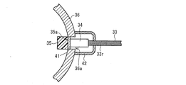
- the emission end portion 33r may be in contact with the laser beam irradiation surface (light receiving surface) 35a, or although not shown, the emission end portion 33r may be arranged with a slight gap between the laser beam irradiation surfaces 35a. Good.
- the laser beam emitted from the emission end portion 33r due to the impact on the headlamp 31 is applied to the laser beam irradiation surface 35a. It may not be properly irradiated. In this case, the laser light is emitted from the reflecting mirror 36 without being converted into incoherent light by the light emitting unit 35.
- the light emitting unit 35 when the light emitting unit 35 is provided so as to contact the transmission filter 37, a space surrounded by the reflection mirror 36 and the transmission filter 37 (the reflection mirror 36 and the reflection mirror 36).
- the laser light propagates through the space formed by the opening of the mirror 36 and is emitted from the reflecting mirror 36.
- the emission end portion 33r is arranged at a slight distance from the laser light irradiation surface 35a, a coherent laser beam having an output level harmful to the human body is emitted to the outside (front) of the headlamp 31.
- a coherent laser beam having an output level harmful to the human body is emitted to the outside (front) of the headlamp 31.
- the laser beam emitted from the semiconductor laser 2 has a high output, it is necessary to prevent the laser beam from being emitted to the outside of the headlamp 31, particularly to the front.
- the emission end portion 33r and the laser light irradiation surface 35a are in contact (close to each other) or the optical path of the laser light is covered. That is, an optical path of the laser beam between the emission end 33r and the laser beam irradiation surface 35a and a space outside the optical path (for example, the reflection mirror 36 and the transmission filter 37). It is preferable to spatially block the enclosed space).
- a hollow portion 36a into which the emission end portion 33r is inserted is formed at the bottom of the reflecting mirror 36, and the laser light irradiation surface 35a of the light emitting portion 35 is formed at the center of the hollow portion 36a.
- the light emitting unit 35 is provided so that the center is located.
- a ferrule 34 that holds the emission end portion 33r is inserted into the hollow portion 36a. That is, as shown in FIG. 6, in the hollow portion 36a of the reflecting mirror 36, the laser light irradiation surface 35a and the emission end portion 33r are close to each other.
- the laser beam emitted from the emission end portion 33r can be reliably irradiated to the laser beam irradiation surface 35a. For this reason, for example, when the headlamp 31 receives some impact, the laser light irradiation surface 35a is not irradiated with laser light having an output level that is harmful to the human body (that is, the laser light is not converted into incoherent light). ) It can prevent leaking directly to the outside. Therefore, a highly safe headlamp 31 can be realized.
- the laser light irradiation surface 35a and the emission end 33r may not be close to each other. . That is, the light emitting unit 35 may be provided so that the laser light irradiation surface 35 a is outside the space formed by the reflecting mirror 36 and the opening of the reflecting mirror 36.
- the “outside of the space” is a concept including the boundary surface of the space and the outside of the space.
- the laser light irradiation surface 35a is at least the same surface as the reflection surface of the reflection mirror 36 that reflects the light emitted from the light emitting unit 35 (the side facing the outside of the reflection mirror 36). That is, the light emitting unit 35 is provided so as to be outside the space.
- the light emitting unit 35 itself may be provided outside the reflecting mirror 36 and inside the headlamp 31. In this case, for example, the light emitting unit 35 is provided inside a cylinder extending from the hollow portion 36a (the material of the cylinder is a material that blocks laser light).
- a part of the light emitting part 35 may exist in the space, and the laser light irradiation surface 35a may exist outside the space (inside the hollow part 36a).
- the shape and size of the laser light irradiation surface 35a are the same as the shape and size of the opening surface of the hollow portion 36a.
- the light emitting unit 35 does not receive high-power laser light inside the space. That is, it is possible to prevent laser light having an output level harmful to the human body from propagating through the space and leaking in the light irradiation direction of the headlamp 31. Further, for example, when the headlamp 31 receives some impact, even if the laser beam is not irradiated onto the laser beam irradiation surface 35a, the laser beam leaks directly in at least the irradiation direction of the light. Can be prevented.
- the hollow portion 36 a is formed at the bottom of the reflecting mirror 36, but is not limited thereto, and may be formed at any position of the reflecting mirror 36.
- the light emitting unit 35 is disposed so as to completely cover the hollow portion 36a. Accordingly, it is possible to prevent the laser light emitted from the emission end portion 33r from being emitted to an area surrounded by the reflection mirror 36 and the transmission filter 37 and emitted from the opening of the reflection mirror 36. For this reason, the hollow portion 36a is formed to be equal to or smaller than the size of the laser light irradiation surface 35a (when the laser light irradiation surface 35a is a rectangle of 3 mm ⁇ 1 mm, the opening surface of the hollow portion 36a is 3 mm 2 or less). Yes. In addition, as long as the light emission part 35 can completely cover the hollow part 36a, the shape of the hollow part 36a does not necessarily have the same shape as the laser light irradiation surface 35a.
- the headlamp 31 In order to reliably prevent the laser light from propagating through the space surrounded by the reflecting mirror 36 and the transmission filter 37, it is preferable to configure the headlamp 31 as shown in FIG. Specifically, (1) the light emitting unit 35 is held by the reflecting mirror 36 instead of the transmission filter 37, (2) the laser light irradiation surface 35a and the emitting end 33r are brought close to each other, and (3) the light emitting unit 35 is It arrange
- the light emitting portion 35 and the ferrule 34 are provided via a heat radiating member 41. That is, the laser beam irradiation surface 35 a and the emission end portion 33 r are close to each other through the heat radiating member 41.
- the heat radiating member 41 dissipates heat generated in the light emitting part 35 when the light emitting part 35 is irradiated with laser light, and is provided in contact with the laser light emitting surface 35a.
- a material that is transparent and has high thermal conductivity such as gallium nitride, magnesia (MgO), or sapphire, is used.
- the heat radiation member 41 is a plate-like member, and is provided inside the hollow portion 36a so as to cover the opening surface of the hollow portion 36a.
- the laser beam irradiation surface 35a is bonded to one surface (laser beam emitting surface) of the heat radiating member 41 so as to be thermally coupled, and the other end (laser beam receiving surface) is in contact with the emitting end portion 33r.
- the light emitting part 35 and the emission end part 33r are arranged so as to be close to each other.
- the shape of the heat radiation member 41 is not limited to a shape that covers the opening surface of the hollow portion 36a as long as the heat generated in the light emitting portion 35 can be dissipated to the reflecting mirror 36, for example. That is, a linear member including a rod shape and a cylindrical shape extending from the reflecting mirror 36 may be in contact with a part of the laser light irradiation surface 35a.
- the heat dissipating member 41 is a linear member and is provided only at a position away from the center of the optical axis (an end portion of the laser light irradiation surface 35a), it is not necessarily transparent. However, from the viewpoint of the utilization efficiency of the laser beam, it is preferable that it is transparent. Further, if the heat radiation member 41 has a cylindrical shape and is provided only at the end of the laser light irradiation surface 35a, a heat radiation effect can be obtained by flowing or circulating a liquid or gas in the cylinder. It is also possible to increase.
- One cause of deterioration of the light emitter is a temperature rise in the irradiation region of the light emitter irradiated with the excitation light and a region in the vicinity thereof (referred to as a temperature rising region).
- a temperature rising region a region in the vicinity thereof.
- the temperature rise in the temperature rising region is suppressed. It is hoped to do.
- the hollow portion 36 a includes the heat radiating member 41, and the emission end portion 33 r and the light emitting portion 35 are close to each other through the heat radiating member 41. Therefore, the heat generated in the light emitting part 35 due to the laser light irradiated on the laser light irradiation surface 35a can be dissipated to the reflecting mirror 36 via the heat radiating member 41, so that the long life of the light emitting part 35 is achieved. Can be achieved. If this point is not taken into consideration, the heat radiating member 41 is not necessarily provided.
- the headlamp 31 includes a light shielding portion 42 as shown in FIG.
- the light shielding portion 42 is provided in the vicinity of the laser light irradiation surface 35a and the emission end portion 33r, of the laser light emitted from the emission end portion 33r, and the laser light irradiation that has not been applied to the laser light irradiation surface 35a. At least one of the laser beams reflected by the surface 35a is shielded.
- the light shielding part 42 and the reflecting mirror 36 form a sealed space that covers at least the vicinity of the laser light irradiation surface 35a and the emission end part 33r. In the configuration illustrated in FIG.
- the material of the light shielding part 42 may be any material as long as it blocks the wavelength of the laser light and the wavelength in the vicinity thereof.
- the light emitting part 35 covers the opening surface of the hollow part 36 a, so that the laser light does not leak into the space surrounded by the reflecting mirror 36 and the transmission filter 37, and the laser light is placed in front of the headlamp 31. Can be prevented from being emitted.
- the laser light is transmitted to the hollow portion 36a (the light emitting portion 35 and the ferrule). 34).
- the light shielding part 42 can reliably prevent the laser light from leaking out of the hollow part 36a. Further, even when the laser light irradiation surface 35a and the emission end portion 33r are separated from each other, the laser light is emitted from the space sealed by the light shielding portion 42, that is, leaks to the outside from the hollow portion 36a. Can be prevented. Note that the light shielding unit 42 is not necessarily provided as long as the purpose is to prevent laser light from being emitted at least in front of the headlamp 31.
- the light shielding portion 42 is provided to prevent the laser light from leaking out of the hollow portion 36a, particularly in the direction toward the outside of the reflecting mirror 36 (the direction other than the light irradiation direction). It has been.
- the present invention is not limited to this configuration, and the light shielding unit 42 may be provided to prevent the laser light from being emitted in the light irradiation direction.
- the light shielding unit 42 is at least a laser beam irradiation surface 35 a when the light emitting unit 35 (laser beam irradiation surface 35 a) is provided inside the reflecting mirror 36. May be provided so as to cover the vicinity of the optical path of the laser beam formed between the laser beam and the emission end portion 33r.
- the light shielding part 42 forms a sealed space that covers at least the laser light irradiation surface 35a and the ferrule 34, and the shape thereof is, for example, a cylindrical shape.
- the material of the light shielding part 42 is preferably a material that blocks the wavelength of the laser light and the wavelength in the vicinity thereof and transmits the light emitted from the light emitting part 35.
- the laser light propagates through the space surrounded by the reflecting mirror 36 and the transmission filter 37 and is emitted from the opening of the reflecting mirror 36. Can be prevented.
- the laser light irradiation surface 35a and the opening surface of the hollow portion 36a have substantially the same size, but the opening surface is smaller than the laser light irradiation surface 35a. Also good.
- the end of the laser light irradiation surface 35 a may be directly connected to the reflecting mirror 36 and held by the reflecting mirror 36.
- FIG. 8 is a block diagram showing the configuration of the control system.
- the headlamps 1, 21, and 31 include an input unit 51, an output control unit 52, and a storage unit 53 as a control system.
- control systems are components of the headlamps 1, 21 and 31, but may be incorporated as part of a control system of a vehicle or the like to which the headlamps 1, 21 and 31 are attached, for example.
- the input unit 51 is a part that receives a user operation such as an instruction to change the output of the semiconductor lasers 2a and 2b, and includes a touch pad.
- the output control unit 52 When receiving the output change instruction input to the input unit 51, the output control unit 52 applies a predetermined drive voltage to the semiconductor lasers 2a and 2b. Alternatively, the output control unit 52 controls the outputs of the semiconductor lasers 2a and 2b so that the drive voltage set at the time of manufacture is applied to the semiconductor lasers 2a and 2b.
- the output control unit 52 reads out the control program stored in the storage unit 53 to a primary storage unit (not shown) configured by, for example, a RAM (Random Access Memory), and executes it, so that the semiconductor lasers 2a and 2b Performs output control processing.
- the storage unit 53 stores a control program executed by the output control unit 52 and data read when the control program is executed (such as a value of a drive voltage applied to the semiconductor lasers 2a and 2b).
- the storage unit 53 includes a nonvolatile storage device such as a ROM (Read Only Memory) flash memory.
- the primary storage unit is configured by a volatile storage device such as a RAM, but the storage unit 53 may also have a function of a primary storage unit.
- a specific example of a combination of the semiconductor lasers 2a and 2b in the headlamp 21 and the phosphor used for the phosphor 23b of the light emitting unit 23 will be described.
- a semiconductor laser that oscillates in blue-violet (wavelength of 400 nm or more and 420 nm or less) is used as the semiconductor laser 2a, and a semiconductor laser that oscillates in red is used as the semiconductor laser 2b.
- a semiconductor laser oscillating in red a semiconductor laser having an AlGaInP active layer formed on a GaAs substrate is suitable.
- a blue phosphor and a green phosphor are used in combination as the phosphor 23b combined with the semiconductor laser 2a.
- a blue-green phosphor may be used instead of the blue phosphor and the green phosphor.
- Each of these phosphors has a refractive index of about 2.
- a material having a refractive index of about 1.8 or less is used among the above-described materials such as silicone and inorganic glass.
- the blue phosphor for example, a JEM phosphor is suitably used.
- Examples of the green phosphor and the blue-green phosphor include various nitride-based or oxynitride-based phosphors.
- the oxynitride phosphor is excellent in heat resistance and is a stable material with high luminous efficiency, it is possible to realize the light emitting portion 23 which is excellent in heat resistance and stable with high luminous efficiency.
- a ⁇ -SiAlON: Eu phosphor doped with Eu 2+ may be used as an oxynitride phosphor that emits green light.
- the oxynitride phosphor that emits blue-green light include a Ca ⁇ -SiAlON: Ce phosphor doped with Ce 3+ .
- the ⁇ -SiAlON: Eu phosphor exhibits strong emission with a peak wavelength of about 540 nm by blue-violet excitation light. The half width of the emission spectrum of this phosphor is about 55 nm.
- the Ca ⁇ -SiAlON: Ce phosphor exhibits strong light emission with a peak wavelength of about 510 nm by blue-violet excitation light.
- ⁇ -SiAlON and ⁇ -SiAlON are phosphors commonly referred to as so-called sialon phosphors among oxynitride phosphors.
- Sialon is a substance in which part of silicon atoms in silicon nitride is replaced with aluminum atoms and part of nitrogen atoms is replaced with oxygen atoms.
- the sialon phosphor can be made by dissolving alumina (Al 2 O 3 ), silica (SiO 2 ), rare earth elements, etc. in silicon nitride (Si 3 N 4 ).
- a phosphor having good characteristics of emitting light in a longer wavelength range than that of a YAG: Ce phosphor can be obtained.
- the reflectance at the interface between the sealing material 23a and the phosphor 23b is 2.7%.
- a sufficient amount of phosphor is dispersed from the viewpoint of laser light scattering. Therefore, the phosphor used as the phosphor 23b can be a good scattering / diffusing material for red laser light.
- the first effect is that the light received by the phosphor is blue-violet light, so that the above-described green phosphor, blue-green phosphor, and blue phosphor all have higher absorptance than blue light.
- the external quantum efficiency (internal quantum efficiency ⁇ absorption rate) of the phosphor is also increased.
- Ca ⁇ -SiAlON: Ce phosphor and JEM phosphor are oxynitride phosphors having high stability and heat resistance, and therefore laser light is used as excitation light. It is suitable for the case.
- Example 2 Next, another specific example of the combination of the semiconductor lasers 2a and 2b in the headlamp 21 and the phosphor used for the phosphor 23b of the light emitting unit 23 will be described.
- a semiconductor laser that oscillates in blue (440 to 470 nm) is used as the semiconductor laser 2a, and a semiconductor laser that oscillates in red as the semiconductor laser 2b (similar to the semiconductor laser used in Example 1). Is used.
- a yellow phosphor for example, YAG: Ce phosphor
- a GAL phosphor aluminate phosphor
- a ⁇ -SiAlON phosphor may be used instead of the yellow phosphor.
- the refractive index of YAG: Ce phosphor is about 1.9-2.
- a material having a refractive index of about 1.8 or less similar to that of the first embodiment, is used among silicone and inorganic glass materials used for general sealing materials. Or you may use said material which has a refractive index of 1.7 or less as the sealing material 23a.
- the YAG: Ce phosphor is an yttrium (Y) -aluminum (Al) -garnet phosphor activated with Ce.
- a YAG: Ce phosphor generally has a broad emission spectrum in which an emission peak exists in the vicinity of 550 nm (slightly longer than 550 nm).
- YAG Ce phosphor
- a YAG: Ce phosphor (NYAG4454) manufactured by Intematix is used.
- the compounding ratio of the YAG: Ce phosphor and the low melting point inorganic glass (low melting point glass) is, for example, about 30: 100.
- the present invention is not limited to this.
- the blending ratio is preferably about 10: 100.
- the reflectance at the interface between the sealing material 23a and the phosphor 23b is 2.7%. Therefore, the phosphor used as the phosphor 23b can be a good scattering / diffusing material for red laser light.
- the following two effects can be obtained by combining the blue laser beam and the above phosphor.
- the aforementioned Ca ⁇ -SiAlON: Ce phosphor and JEM phosphor are hardly excited by blue light.
- the ⁇ -SiAlON phosphor has a slightly lower efficiency (about several percent) than blue-violet light, it can be excited well with blue light.
- the GAL phosphor can also be excited well with blue light.
- a ⁇ -SiAlON phosphor which is a kind of oxynitride phosphor, is optimal.
- the GAL phosphor is also excellent in reliability, it is suitable when laser light is used as excitation light.
- the headlamps 1, 21, and 31 include the semiconductor laser 2a that oscillates at a blue-violet or blue wavelength and the semiconductor laser 2b that oscillates a laser beam at a red wavelength, as excitation light sources. Furthermore, the headlamps 1, 21 and 31 diffuse the laser light emitted from the semiconductor laser 2b and the light emitting units 7 and 23 including the phosphors 7b and 23b that emit fluorescence when excited by the laser light from the semiconductor laser 2a. And a diffusing unit 8 (light emitting unit 23).
- the red light is obtained by the laser light from the semiconductor laser 2b without using the red phosphor.
- red light is included as illumination light without essentially including light in a region with low or no visibility, as in the conventional case of using a red phosphor to obtain red light. be able to. Therefore, it is possible to obtain the headlamps 1, 21, 31 that have good red color rendering (reproducibility) and emit light with low power consumption.
- FIG. 9 is a graph showing current versus light output characteristics of a red semiconductor laser.
- FIG. 10 is a graph showing an emission spectrum of the red semiconductor laser.
- the red semiconductor laser emits light with an output that has a substantially linear relationship with a current of 5 A or more. Further, as shown in FIG. 10, it can be seen that the light of the red semiconductor laser includes only light in the vicinity of 635 nm and does not include light of 640 nm or more. Thus, by using a red semiconductor laser, red light with extremely strong monochromaticity can be generated, and all the generated light can be made visible light. Therefore, it is possible to obtain a light source capable of emitting light with low power consumption, which is more efficient than a conventional white LED.
- the oscillation wavelength of the semiconductor laser 2b is preferably 600 nm or more and 675 nm or less. Thereby, red visibility can be improved.
- the absorption rate of the phosphor 23b of the light emitting unit 23 is 10% or less at the oscillation wavelength of the semiconductor laser 2b.
- Ca ⁇ -SiAlON: Ce phosphor Ce phosphor
- JEM phosphor YAG: Ce phosphor
- GAL phosphor or ⁇ -SiAlON phosphor is preferably used.
- the YAG: Ce phosphor has an absorptance of 1% or less in a wavelength region of 600 nm or more, and can scatter and diffuse almost without absorbing red light.
- a YAG: Ce phosphor When using a YAG: Ce phosphor, it is preferable to use a semiconductor laser having an oscillation wavelength of 440 nm or more and 470 nm or less as the semiconductor laser 2a.
- a GAL phosphor that is an aluminate phosphor may be used. Thereby, pseudo white light is obtained by the color mixture of the laser light in the blue region of the semiconductor laser 2a and the light emitted from the light emitting unit 23.
- the light emitting section 23 has a sealing material 23a in which the phosphor 23b is dispersed, and the refractive index of the sealing material 23a is preferably smaller than the refractive index of the phosphor 23b.
- the phosphor 23b functions as a scatterer that only scatters and diffuses without absorbing red light.
- Patent Document 1 includes a GaN-based semiconductor laser that emits laser light having a wavelength of 450 nm or less as an excitation light source, and the phosphor emits fluorescence in the visible region when excited by the laser light from the excitation light source.
- a light emitting device having a configuration combined with the above is disclosed.
- FIG. 15 Next, another embodiment of the present invention will be described with reference to FIGS. 15 to 21.
- FIG. 15 is a diagram illustrating a schematic configuration of the headlamp 201.
- the headlamp 201 includes a semiconductor laser (excitation light source) 202, an aspheric lens 203, a light guide unit 204, a light emitter 205, a reflecting mirror 206, and a transmission filter (optical filter) 207.
- the semiconductor laser 202 functions as an excitation light source that generates excitation light.
- One or more semiconductor lasers 202 may be provided. Further, as the semiconductor laser 202, one having one light emitting point on one chip (one chip, one stripe) may be used, or one having a plurality of light emitting points (one chip, plural stripes) may be used. In this embodiment, a one-chip, one-stripe semiconductor laser 202 is used. In the present embodiment, the semiconductor laser 202 is used as the excitation light source, but the excitation light source is not limited to this. For example, an LED lamp 221 described later may be used as the excitation light source.
- the semiconductor laser 202 for example, oscillates 405 nm (blue-violet) laser light, has a light output of 1.0 W, an operating voltage of 5 V, a current of 0.7 A, and a package (stem) having a diameter of 5.6 mm. Is enclosed. In this embodiment, ten semiconductor lasers 202 are used, and the total light output is 10 W.
- FIG. 15 shows only one semiconductor laser 202 for convenience.
- the wavelength of the laser light oscillated by the semiconductor laser 202 is not limited to 405 nm, and the wavelength from the near ultraviolet region to the blue region (350 nm or more and 460 nm or less), more preferably from the near ultraviolet region to the blue-violet region (370 nm or more and 420 nm or less). Any material having a peak wavelength (emission peak wavelength) in the range (first wavelength region) may be used.
- the light output of the semiconductor laser 202 is 1 W or more and 20 W or less, and the laser light emitted to the light emitter 205 is irradiated.
- the light density is preferably 0.1 W / mm 2 or more and 50 W / mm 2 or less. If the light output is within this range, it is possible to achieve the luminous flux and brightness required for the vehicle headlamp and to prevent the light emitter 205 from being extremely deteriorated by the high-power laser light. That is, it is possible to realize a light source having a long lifetime while having a high luminous flux and a high luminance.
- FIG. 21A is a circuit diagram of an LED lamp (excitation light source) 221 which is an example of an excitation light source
- FIG. 21B is a front view showing an appearance of the LED lamp 221.
- the LED lamp 221 has a configuration in which an LED chip (excitation light source) 410 connected to an anode 214 and a cathode 215 is sealed with an epoxy resin cap 216.
- the LED chip 410 has a pn junction between a p-type semiconductor 331 and an n-type semiconductor 332, an anode 214 is connected to the p-type electrode 333, and a cathode 215 is connected to the n-type electrode 334. Connected.
- the LED chip 410 is connected to the power source E through the resistor R.
- a circuit is configured, and when power is supplied from the power source E to the LED chip 410, incoherent excitation light is generated near the pn junction.
- the material of the LED chip 410 is a compound semiconductor such as indium gallium nitride (InGaN), gallium nitride (GaN), or aluminum gallium nitride (AlGaN) as a material that generates excitation light having a wavelength from the near ultraviolet region to the blue-violet region.
- InGaN indium gallium nitride
- GaN gallium nitride
- AlGaN aluminum gallium nitride
- Other materials include diamond (C) that emits excitation light having a wavelength in the near ultraviolet region, zinc selenide (ZnSe) that generates excitation light having a wavelength in the blue region, and wavelengths from the near ultraviolet region to the blue-violet region.
- ZnO zinc oxide
- GaAsP whose emission color is orange such as GaP, AlGaAs, and GaAsP whose emission color is red, and yellow light that is colored.
- Compound semiconductors such as GaAsP and GaP, GaP whose emission color is green, SiC and GaN whose emission color is blue can be exemplified.
- the LED chip 410 operates at a low voltage of about 2V to 4V, is small and light, has a fast response speed, has a long life, and is low in cost.
- the basic structure of the semiconductor laser 202 described above is the same as the basic structure described for the semiconductor lasers 2a and 2b described above, and therefore the description thereof is omitted here.
- the aspheric lens 203 is a lens for causing the laser light oscillated from each semiconductor laser 202 to enter the light incident surface 204 a that is one end of the light guide unit 204.
- the aspherical lens 203 FLKN1 405 manufactured by Alps Electric can be used.
- the shape and material of the aspherical lens 203 are not particularly limited as long as the lens has the above function, but it is preferably a material having high transmittance near 405 nm and good heat resistance.
- the aspheric lens 203 is for converging the laser light oscillated from the semiconductor laser 202 and guiding it to a relatively small light incident surface (for example, a diameter of 1 mm or less). For this reason, when the light incident surface 204a of the light guide unit 204 is large enough not to converge the laser light, it is not necessary to provide the aspheric lens 203.
- the light guide unit 204 is a truncated cone-shaped light guide member that condenses the laser light oscillated by the semiconductor laser 202 and guides it to the light emitter 205 (the laser light irradiation surface of the light emitter 205). It is optically coupled to the semiconductor laser 202 via the lens 203 (or directly).
- the light guide unit 204 includes a light incident surface 204a (incident end) that receives the laser light emitted from the semiconductor laser 202, and a light emission surface 204b (exit) that emits the laser light received at the light incident surface 204a to the light emitter 205. End).
- the area of the light emitting surface 204b is smaller than the area of the light incident surface 204a. Therefore, each laser beam incident from the light incident surface 204a is converged and emitted from the light emitting surface 204b by moving forward while being reflected on the side surface of the light guide unit 204.
- the light guide unit 204 is made of BK7 (borosilicate crown glass), quartz glass, acrylic resin, or other transparent material. Further, the light incident surface 204a and the light emitting surface 204b may be planar or curved.
- the light guide unit 204 may have a truncated pyramid shape or an optical fiber as long as it can guide the laser light from the semiconductor laser 202 to the light emitter 205. Further, the light emitter 205 may be irradiated with the laser light from the semiconductor laser 202 via the aspherical lens 203 or directly without providing the light guide unit 204. Such a configuration is possible when the distance between the semiconductor laser 202 and the light emitter 205 is short.
- FIG. 16A schematically shows an example of the composition of the light emitter 205 of the present embodiment.
- FIGS. 16B and 16C are diagrams schematically showing another example of the composition of the light emitter 205 of the present embodiment. Note that these drawings are not drawn in accordance with the shape and size of each constituent element of the light emitter 205, but are merely diagrams schematically showing the composition of the light emitter 205.
- white (or pseudo-white) light used as illumination light can be realized by mixing three colors satisfying the principle of equal colors, or mixing two colors satisfying a complementary color relationship. Based on the principle / relationship of the same color or complementary color, for example, white (or pseudo-white) light can be realized by a mixture of fluorescent colors emitted from each of the plurality of phosphors included in the light emitter 205.
- the light emitting body 205 is a blue light emitting phosphor 258 (first phosphor), and a yellow light emitting phosphor 259 (second phosphor) is the sealing material 256.
- the phosphors are dispersed (that is, the light emitter 205 is formed by mixing phosphors).
- the blue light emitting phosphor 258 is a phosphor having a peak wavelength in a second wavelength region longer than the wavelength region (first wavelength region) of excitation light, that is, in a wavelength range of 440 nm to 490 nm.
- the yellow light-emitting phosphor 259 is a phosphor that is excited by blue light emitted from the blue light-emitting phosphor 258.
- the blue light emitting phosphor 258 does not have an absorption spectrum valley in the first wavelength region, and phosphors other than the blue light emitting phosphor 258 have an absorption spectrum valley in the first wavelength region. . That is, the yellow light-emitting phosphor 259 has a higher probability of not absorbing excitation light than the blue light-emitting phosphor 258, and has a higher probability of scattering or diffusing the excitation light. Therefore, if the yellow light emitting phosphor 259 is not present while suppressing unnecessary absorption of the excitation light inside the light emitter 205, the excitation light that may have been emitted to the outside as it is is emitted by the yellow light emitting phosphor 259. Since the light is scattered or diffused, the scattering efficiency of the excitation light inside the light emitter 205 is improved.
- the yellow light emitting phosphor 259 is excited by the blue light generated from the blue light emitting phosphor 258 as described above. Thereby, the yellow light-emitting phosphor 259 can also emit fluorescence. Therefore, the fluorescence of the blue light-emitting phosphor 258 and the fluorescence of the yellow light-emitting phosphor 259 can be emitted to the outside as illumination light. As described above, according to the light emitter 205, the light emission efficiency of the light emitter 205 as a whole is improved.
- the light emitter 205 can adjust the color (chromaticity) and color rendering of the illumination light by adjusting the weight ratio of the blue light emitting phosphor 258 to the yellow light emitting phosphor 259. it can.
- the light emitter 205 includes a combination of the blue light emitting phosphor 258 and the yellow light emitting phosphor 259, (pseudo) white light can be realized.
- irradiation light generated from the light emitter 205 emits light emission efficiency.
- the sealing material 256 that seals each phosphor is preferably an inorganic glass having a low melting point.
- a resin such as a silicone resin is used as long as excitation light with extremely high output and high light density is not used. Or organic hybrid glass may be sufficient.
- the light-emitting body 205 is one in which each phosphor is dispersed in a sealing material. This is because, when only each phosphor is pressed and consolidated, deterioration of the light emitter 205 caused by irradiation with laser light may be promoted.
- a phosphor that emits fluorescence having a peak wavelength in the blue region is hereinafter referred to as a blue-emitting phosphor.
- a phosphor that emits fluorescence having a peak wavelength in the yellow region is called a yellow-emitting phosphor.
- blue light is fluorescence having a peak wavelength in a wavelength range of 440 nm to 490 nm, for example.
- yellow light is, for example, fluorescence having a peak wavelength in a wavelength range of 560 nm to 590 nm.
- the light emitter 205 includes a blue light emitting phosphor 258 (first phosphor) and a yellow light emitting phosphor 259 (second fluorescence) dispersed in a sealing material 256.
- the body is configured independently and separately.
- the blue light emitting phosphor 258 (first phosphor) is configured to be surrounded by the yellow light emitting phosphor 259 (second phosphor).
- the cross-sectional shapes of the blue light-emitting phosphor 258 and the yellow light-emitting phosphor are a circular shape and an annular shape, respectively, but the cross-sectional shapes of these phosphors are not limited to the circular shape and the circular shape.
- the cross-sectional shapes of the blue light-emitting phosphor 258 and the yellow light-emitting phosphor may be a square shape and a square ring shape, or other polygons and polygon rings, respectively.
- the luminous body 205 can increase the luminous efficiency of the luminous body even when the blue luminous phosphor 258 and the yellow luminous phosphor 259 are independently present separately.
- the light emitting body 205 includes a blue light emitting phosphor 258 and a yellow light emitting phosphor 259 that are dispersed in the sealing material 256 as in the configuration of FIG. 16 (b).
- the blue light emitting phosphor 258 is configured to be surrounded by the yellow light emitting phosphor 259.
- a blue light-emitting phosphor 258 surrounds the periphery.
- the cross-sectional shapes of the blue light emitting phosphor 258 and the yellow light emitting phosphor 259 are circular and annular, respectively.
- the cross-sectional shape is not limited to a circular shape and an annular shape.
- the cross-sectional shapes of the blue light emitting phosphor 258 and the yellow light emitting phosphor may be a quadrangle and a square ring, respectively.
- the luminous body 205 can increase the luminous efficiency of the luminous body even when the blue luminous phosphor 258 and the yellow luminous phosphor 259 are independently present separately.
- the weight ratio of the blue light emitting phosphor 258 and the yellow light emitting phosphor 259 will be described.
- the weight ratio of the blue light-emitting phosphor 258 to the yellow light-emitting phosphor 259 is preferably 1 or more and 5 or less. By setting this ratio, it is possible to realize a light emitter having suitable light emission efficiency, chromaticity and color rendering properties.
- Blue light emitting phosphor 258 Specific examples of the blue light emitting phosphor 258 include Eu-activated barium magnesium aluminate phosphor, BaMgAl 10 O 17 : Eu (hereinafter abbreviated as “BAM phosphor”). This BAM phosphor has an emission peak wavelength of 455 nm.
- JEM phase phosphor Another example is an oxynitride-based phosphor containing a JEM phase (JEM phase phosphor).
- the JEM phase phosphor is a substance that has been confirmed to be produced in a process for preparing a sialon phosphor stabilized by a rare earth element.
- the JEM phase is a ceramic discovered as a grain boundary phase of a silicon nitride-based material, and generally has a composition formula M 1 Al (Si 6-z Al z ) N 10-z O z (where M 1 Is represented by La, Ce, Pr, Nd, Sm, Eu, Gd, Tb, Dy, Ho, Er, Tm, Yb, and Lu), and z is a parameter.
- M 1 Is represented by La, Ce, Pr, Nd, Sm, Eu, Gd, Tb, Dy, Ho, Er, Tm, Yb, and Lu
- z is a parameter.
- It is a crystal phase (oxynitride
- a Ce 3+ activated JEM phase phosphor (JEM phase: Ce phosphor) is preferable.
- the Ce component contained in the JEM phase phosphor absorbs excitation light in the vicinity of 350 nm to 400 nm, makes it easy to obtain light emission from blue to blue-green, and broadens the half-value width of light emission. It is possible to sufficiently cover a wavelength range with high relative visibility in visual observation.
- the JEM phase: Ce phosphor has a peak wavelength of 480 nm when the excitation wavelength is 360 nm, and the luminous efficiency at that time is 60%. Further, when the excitation wavelength is 405 nm, the peak wavelength is 490 nm, and the light emission efficiency at that time is 50%.
- yellow-emitting phosphor 259 Specific examples of the yellow light emitting phosphor 259 include yttrium (Y) -aluminum (Al) -garnet-based YAG: Ce phosphors activated by cerium (Ce), terbium (Tb)- Examples thereof include a TAG: Ce phosphor that is an aluminum (Al) -garnet phosphor.
- the YAG: Ce phosphor has a broad emission spectrum in which an emission peak exists in the vicinity of 550 nm (slightly longer than 550 nm). In addition, as shown in FIG. 17, there is a valley of the absorption spectrum in the wavelength range near 360 nm to 420 nm (first wavelength region). In other words, the light absorptance is low in the wavelength region. That is, the YAG: Ce phosphor has a higher probability of not absorbing the excitation light in the present embodiment than the blue light-emitting phosphor 258, and has a higher probability of scattering or diffusing the excitation light.
- the YAG: Ce phosphor does not exist while suppressing unnecessary absorption of the excitation light inside the light emitter 205, the excitation light that may have been emitted to the outside as it is is transmitted by the YAG: Ce phosphor. Since the light is scattered or diffused, the scattering efficiency of the excitation light inside the light emitter 205 is improved.
- the TAG: Ce phosphor has an emission spectrum in which an emission peak exists in the vicinity of 570 nm. Further, as shown in FIG. 18, the absorption spectrum has a trough in the wavelength range near 350 nm to 420 nm (in the first wavelength range). In other words, the light absorptance is low in the wavelength region. That is, the TAG: Ce phosphor has a higher probability of not absorbing the excitation light in the present embodiment than the blue light-emitting phosphor 258, and has a higher probability of scattering or diffusing the excitation light.
- the TAG: Ce phosphor does not exist while suppressing unnecessary absorption of the excitation light inside the light emitter 205, the excitation light that may have been emitted to the outside as it is is output by the TAG: Ce phosphor. Since the light is scattered or diffused, the scattering efficiency of the excitation light inside the light emitter 205 is improved.
- FIGS. 17 and 18 are graphs showing the internal quantum efficiency, the absorption rate, and the external quantum efficiency of the YAG: Ce phosphor and the TAG: Ce phosphor, respectively.
- the horizontal axis represents the wavelength
- the vertical axis represents the respective efficiencies (internal quantum efficiency, absorption rate, and external quantum efficiency).
- the absorptance around 360 nm to 410 nm is low. That is, when using a YAG: Ce phosphor, it is preferable to use laser light having a wavelength in the range (first wavelength region) included in 360 nm to 410 nm as excitation light.
- the absorptance around 350 nm to 420 nm is low. That is, when a TAG: Ce phosphor is used, it is preferable to use laser light having a wavelength in the range (first wavelength region) included in 350 nm to 420 nm as excitation light.
- This figure is a graph showing the absorption rate (efficiency) of the JEM layer: Ce phosphor.
- the horizontal axis represents wavelength
- the vertical axis represents absorption rate.
- FIG. 20 is a graph showing the chromaticity range of illumination light.
- JEM phase Ce phosphor (peak wavelength: about 480 nm, see point 236)
- YAG Ce phosphor (peak wavelength: about 550 nm, see point 31)
- TAG Ce phosphor (peak wavelength: about 570 nm, see point 232)
- BAM phosphor peak wavelength: about 455 nm, see point 237).
- the curve 233 in the figure shows the color temperature (K: Kelvin).
- K Kelvin
- a polygon having six points 235 as apexes shown in the figure indicates a chromaticity range of white light required for a vehicle headlamp defined by law.
- an arbitrary chromaticity range indicated by a straight line 238 connecting the points 232 and 237 is included.
- the light emitter 205 that can emit illumination light of chromaticity can be manufactured.
- the chromaticity range indicated by the straight line 238 overlaps the chromaticity range of white light required for the vehicle headlamp. Therefore, it is possible to manufacture a light emitter 205 suitable for a vehicle headlamp by adjusting the blending ratio of the two types of phosphors.
- the vehicle headlamp is required regardless of the material and the number of types of each phosphor. What is necessary is just to adjust the mixture ratio of each fluorescent substance contained in the light-emitting body 205 so that the illumination light of the chromaticity contained in the chromaticity range of white light can be radiated
- the luminous body 205 is fixed to the focal position of the reflecting mirror 206 or in the vicinity thereof on the inner surface of the transmission filter 207 (the side on which the light emitting surface 204b is located).
- the method of fixing the position of the light emitter 205 is not limited to this method, and the position of the light emitter 205 may be fixed by a rod-like or cylindrical member (preferably transparent) extending from the reflecting mirror 206. .
- the shape of the light emitter 205 is not particularly limited, and may be a rectangular parallelepiped or a cylindrical shape.
- the headlamp 201 has a cylindrical shape.
- the cylindrical light emitter 205 has a cylindrical shape with a diameter of 2 mm and a thickness (height) of 0.8 mm.
- the laser light irradiation surface that is a surface on which the light emitter 205 is irradiated with laser light is not necessarily a flat surface, and may be a curved surface. However, in order to control the reflection of the laser beam, the laser beam irradiation surface is preferably a plane perpendicular to the optical axis of the laser beam.
- the thickness of the cylindrical light emitting body 205 may not be 0.8 mm. Further, the thickness of the light emitter 205 required here varies according to the ratio of the sealing material and the phosphor in the light emitter 205. If the phosphor content in the light emitter 205 is increased, the efficiency of conversion of laser light into white light increases, so that the thickness of the cylindrical light emitter 205 can be reduced.
- the reflection mirror 206 reflects the fluorescence (illumination light) emitted from the light emitter 205 to form a light bundle that travels within a predetermined solid angle. That is, the reflecting mirror 206 reflects the light from the light emitter 205 to form a light beam that travels forward of the headlamp 201.
- the reflecting mirror 206 is, for example, a curved (cup-shaped) member having a metal thin film formed on the surface thereof, and opens in the traveling direction of the reflected light.
- the transmission filter 207 is a transparent resin plate that covers the opening of the reflecting mirror 206, and holds the light emitter 205.
- the transmission filter 207 is made of a material that blocks laser light from the semiconductor laser 202 and transmits (pseudo) white light (incoherent light) generated by converting the laser light in the light emitter 205. It is preferable that an inorganic glass plate or the like can be used in addition to the resin plate.
- the transmission filter 207 for example, TY418 manufactured by Isuzu Seiko Glass Co., Ltd. is available.
- the transmission filter 207 does not have to block all the laser light and transmit all the fluorescence emitted from the light emitter 205. That is, the transmission filter 207 is attenuated to such an extent that direct light from the semiconductor laser 202 that emits laser light, which is harmful to the human body (the emission point of the semiconductor laser 202 itself) cannot be directly viewed, and the amount of transmission is safe. All of the components may not be blocked, and if the fluorescent light having a sufficient amount of light (or sufficiently high color temperature) is emitted as the white light of the headlamp 201, it may not be possible to transmit all the fluorescent light.
- the light emitter 205 receives the laser light emitted from the semiconductor laser 202 and emits light, and the fluorescence is emitted through the transmission filter 207. At this time, since the laser beam is blocked by the transmission filter 207, it does not leak outside. As a result, it is possible to prevent human eyes from being damaged by emitting laser light that has not been converted into fluorescence (or that has not been scattered or diffused) to the outside.
- the excitation light source is an LED
- the light from the LED has a very large light emission point size compared to the semiconductor laser 202, so that it is not necessary to block the light. For this reason, in most cases, there is no problem even if the light emitted from the LED is directly emitted to the outside of the illumination device.
- the pumping light source is the semiconductor laser 202
- the light from the semiconductor laser 202 having a very small light emitting point is highly dangerous when incident on the human eye as it is. It is necessary to block direct light from the light emitting point 202. Therefore, in the present embodiment, a transmission filter 207 is provided.
- the laser light oscillated from the semiconductor laser 202 is irradiated onto the phosphor included in the light emitter 205, so that electrons existing in the phosphor are excited from a low energy state to a high energy state (excited state).
- the phosphors emit light when the electrons excited to the high energy state transition to the low energy state.
- a headlamp (illumination device, headlamp) 20 according to another embodiment of the present invention will be described below with reference to FIGS.
- symbol is attached
- a projector-type headlamp 220 will be described.
- FIG. 22 is a cross-sectional view showing a configuration of a headlamp 220 that is a projector-type headlamp.
- the headlamp 220 is different from the headlamp 201 in that it is a projector-type headlamp and that an optical fiber bundle (light guide) 40 is provided instead of the light guide 204.
- the optical fiber bundle 240 is a bundle of a plurality of optical fibers (light guide portions) 240a, and each of the optical fibers 240a has an incident end portion on which laser light is incident and an output end portion that emits laser light.
- the headlamp 220 includes a semiconductor laser 202, an aspheric lens 203, an optical fiber bundle 240, a ferrule 209, a light emitter 205, a reflecting mirror 206, a transmission filter (optical filter) 207, a housing 210, an extension 211, A lens 212, a convex lens 213, and a lens holder 208 are provided.
- the semiconductor laser 202, the optical fiber bundle 240, the ferrule 209, and the light emitter 205 form the basic structure of the light emitting device.
- the headlamp 220 is a projector-type headlamp
- the headlamp 220 includes a convex lens 213.
- the present invention may be applied to other types of headlamps (for example, semi-shielded beam headlamps), in which case the convex lens 213 can be omitted.
- the aspherical lens 203 is as described above, in this embodiment, the laser light (excitation light) oscillated from the semiconductor laser 202 is incident on the incident end that is one end of the optical fiber 240a. It is a lens. Further, as many aspheric lenses 203 as the number of optical fibers 240a are provided.
- the optical fiber bundle 240 is a light guide member that guides the laser light oscillated by the semiconductor laser 202 to the light emitter 205.
- Each optical fiber 240a of the optical fiber bundle 240 has a two-layer structure in which the core of the core is covered with a clad having a refractive index lower than that of the core.
- the core is mainly composed of quartz glass (silicon oxide) having almost no absorption loss of laser light
- the clad is composed mainly of quartz glass or a synthetic resin material having a refractive index lower than that of the core. .
- the optical fiber 240a is made of quartz having a core diameter of 200 ⁇ m, a cladding diameter of 240 ⁇ m, and a numerical aperture NA of 0.22, but the structure, thickness, and material of the optical fiber 240a are limited to those described above.
- the cross section perpendicular to the major axis direction of the optical fiber 240a may be rectangular.
- the optical fiber 240a has a plurality of incident end portions that receive the laser light and a plurality of emission end portions that emit the laser light incident from the incident end portion. As will be described later, the emission end portions of the plurality of optical fibers 240a are positioned with respect to the laser light irradiation surface (light receiving surface) of the light emitter 205 by a ferrule 209.
- FIG. 23 is a diagram showing the positional relationship between the emission end of each optical fiber 240 a of the optical fiber bundle 240 and the light emitter 205.
- the ferrule 209 holds the emission end portion of the optical fiber 240a in a predetermined pattern with respect to the laser light irradiation surface of the light emitter 205.
- the ferrule 209 may be formed with holes for inserting the optical fiber 240a in a predetermined pattern, and can be separated into an upper part and a lower part, and grooves formed on the upper and lower joint surfaces, respectively.
- the optical fiber 240a may be sandwiched between the two.
- the material of the ferrule 209 is not particularly limited, and is, for example, stainless steel. In FIG. 23, three optical fibers 240a are shown, but the number of optical fibers 240a is not limited to three. Further, the ferrule 209 may be fixed by a rod-shaped member or the like extending from the reflecting mirror 206.
- the portion with the highest light intensity (maximum light intensity portion) in the light intensity distribution of the laser light emitted from the plurality of optical fibers 240 a is the light emitting body 205. Different parts are irradiated. With this configuration, it is possible to prevent the light emitter 205 from being significantly deteriorated due to the concentration of laser light at one point. Note that the emission end portion may be in contact with the laser light irradiation surface, or may be disposed at a slight interval.
- the bundles of the optical fibers 240a may be collectively positioned by the ferrule 209.
- the reflecting mirror 206 is, for example, a member having a metal thin film formed on the surface thereof, and reflects the light emitted from the light emitter 205, thereby converging the light to the focal point. Since the headlamp 220 is a projector-type headlamp, the basic shape of the reflecting mirror 206 has an elliptical cross section parallel to the optical axis direction of the reflected light.
- the reflecting mirror 206 has a first focal point and a second focal point, and the second focal point is located closer to the opening of the reflecting mirror 206 than the first focal point.
- a convex lens 213, which will be described later, is disposed so that its focal point is located in the vicinity of the second focal point, and projects light converged on the second focal point by the reflecting mirror 206 to the front.
- the transmission filter 207 blocks the excitation light and transmits the fluorescence emitted from the light emitter 205 as described above, and holds the light emitter 205. By providing the transmission filter 207, it is possible to prevent the laser light emitted from the semiconductor laser 202 from leaking directly to the outside.
- the convex lens 213 collects the light emitted from the light emitter 205 and projects the collected light to the front of the headlamp 201.
- the focal point of the convex lens 213 is in the vicinity of the second focal point of the reflecting mirror 206, and its optical axis passes through almost the center of the light emitting surface of the light emitter 205.
- the convex lens 213 is held by a lens holder 208, and a relative position with respect to the reflecting mirror 206 is defined.
- the lens holder 208 may be formed as a part of the reflecting mirror 206.
- the housing 210 forms the main body of the headlamp 220 and houses the reflecting mirror 206 and the like.
- the optical fiber bundle 240 passes through the housing 210, and the semiconductor laser 202 is installed outside the housing 210.
- the semiconductor laser 202 generates heat when the laser beam is oscillated, but the semiconductor laser 202 can be efficiently cooled by being installed outside the housing 210. Further, since the semiconductor laser 202 may break down, it is preferable to install it at a position where it can be easily replaced. If these points are not taken into consideration, the semiconductor laser 202 may be housed inside the housing 210.
- the extension 211 is provided on the front side of the reflecting mirror 206 to improve the appearance by concealing the internal structure of the headlamp 220 and to enhance the sense of unity between the reflecting mirror 206 and the vehicle body.
- the extension 211 is also a member having a metal thin film formed on the surface thereof, like the reflecting mirror 206.
- the lens 212 is provided in the opening of the housing 210 and seals the headlamp 220. Light emitted from the light emitter 205 is emitted to the front of the headlamp 201 through the lens 212.
- the structure of the headlamp itself may be any, and what is important in the present invention is that the composition of the light emitter 205 is generated from the blue light emitting phosphor 258 and the blue light emitting phosphor 258.
- FIG. 24 is a cross-sectional view illustrating a schematic configuration of the headlamp 201 according to the present embodiment
- FIG. 25 is a diagram illustrating a positional relationship between the light emitter 205 and the emission end portion 240r of the optical fiber bundle 240.
- the emission end portion 240r may be in contact with the laser light irradiation surface (light receiving surface) 205a, or may be arranged at a slight interval as shown in FIG.
- the laser light emitted from the emission end portion 240r is applied to the laser light irradiation surface 205a due to the impact on the headlamp 220. It may not be properly irradiated.
- the laser light is emitted from the reflecting mirror 206 without being converted into incoherent light by the light emitter 205.
- the light emitter 205 is provided in the transmission filter 207 as shown in FIG. 22, the space surrounded by the reflection mirror 206 and the transmission filter 207 (the reflection mirror 206 and the opening of the reflection mirror 206 are separated).
- the laser beam propagates through the space to be formed and is emitted from the reflecting mirror 206.
- the emission end portion 240r is arranged slightly spaced from the laser light irradiation surface 205a (particularly in the case of the configuration shown in FIG. 22), coherent laser light having an output level harmful to the human body is applied to the head. There is a possibility that the light is emitted to the outside (front) of the lamp 220. In particular, since the laser light emitted from the semiconductor laser 202 has a high output, it is necessary to prevent the laser light from being emitted to the outside of the headlamp 201, particularly forward.
- the emission end portion 240r and the laser light irradiation surface 205a are in contact (close to each other) or the optical path of the laser light is covered. That is, the optical path of the laser beam between the emission end portion 240r and the laser beam irradiation surface 205a is separated, and the space outside the optical path (for example, the reflection mirror 206 and the transmission filter 207). It is preferable to spatially block the space surrounded by.
- a hollow portion 206a into which the emission end portion 240r is inserted is formed at the bottom of the reflecting mirror 206, and the center of the laser light irradiation surface 205a of the light emitter 205 is located at the center of the hollow portion 206a.
- a light emitter 205 is provided.
- a ferrule 209 that holds the emission end portion 240r is inserted into the hollow portion 206a. That is, in FIG. 24, in the hollow part 206a of the reflecting mirror 206, the laser beam irradiation surface 205a and the emission end part 240r are close to each other.
- the laser beam irradiation surface 205a and the emission end portion 240r are close to each other, the laser beam emitted from the emission end portion 240r can be reliably irradiated onto the laser beam irradiation surface 205a. For this reason, for example, when the headlamp 230 receives some impact, the laser light irradiation surface 205a is not irradiated with laser light having an output level that is harmful to the human body (that is, the laser light is not converted into incoherent light). B) It can be prevented from leaking directly to the outside. Therefore, a highly safe headlamp 230 can be realized.
- the laser beam irradiation surface 205a and the emission end 240r are not close to each other.
- the light emitter 205 may be provided so that the laser light irradiation surface 205a is outside the space formed by the reflecting mirror 206 and the opening of the reflecting mirror 206.
- the “outside of the space” is a concept including the boundary surface of the space and the outside of the space.
- the laser light irradiation surface 205a is at least the same surface as the reflecting surface of the reflecting mirror 206 that reflects the light emitted from the light emitter 205 (ie, the side facing the outside of the reflecting mirror 206, ie, the aforementioned A light emitter 205 is provided so as to be outside the space. Further, the light emitter 205 itself may be provided outside the reflecting mirror 206 and inside the headlamp 230. In this case, for example, the light emitter 205 is provided inside a cylinder (the material of the cylinder is a material that blocks laser light) obtained by extending the hollow portion 206a.
- a part of the light emitter 205 may exist in the space, and the laser light irradiation surface 205a may exist outside the space (inside the hollow portion 206a).
- the shape and size of the laser light irradiation surface 205a are identical to the shape and size of the opening surface of the hollow portion 206a.
- the light emitter 205 does not receive high-power laser light inside the space. That is, it is possible to prevent laser light having an output level harmful to the human body from propagating through the space and leaking in the light irradiation direction of the headlamp 230. Further, for example, when the headlamp 230 is subjected to some impact, even if a situation occurs in which the laser beam is not irradiated onto the laser beam irradiation surface 205a, the laser beam leaks directly in at least the irradiation direction of the light. Can be prevented.
- the hollow portion 206a is formed at the bottom of the reflecting mirror 206, but is not limited thereto, and may be formed at any position of the reflecting mirror 206.
- the light emitter 205 is disposed so as to completely cover the hollow portion 206a. Accordingly, it is possible to prevent the laser light emitted from the emission end portion 240r from being emitted to an area surrounded by the reflection mirror 206 and the transmission filter 207 and emitted from the opening of the reflection mirror 206. For this reason, the hollow portion 206a is formed to be equal to or smaller than the size of the laser light irradiation surface 205a (when the laser light irradiation surface 205a is a rectangle of 3 mm ⁇ 1 mm, the opening surface of the hollow portion 206a is 3 mm 2 or less). Yes. Note that the shape of the hollow portion 206a is not necessarily the same as that of the laser light irradiation surface 205a as long as the light emitter 205 can completely cover the hollow portion 206a.
- the luminous body 205 is held by the reflection mirror 206 instead of the transmission filter 207; 2) It is preferable that the laser light irradiation surface 205a and the emission end portion 240r are brought close to each other, and (3) the light emitter 205 is disposed so as to completely cover the hollow portion 206a.
- the light emitter 205 and the ferrule 209 are provided via a heat dissipating member 261. That is, the laser beam irradiation surface 205a and the emission end portion 240r are close to each other via the heat dissipation member 261.
- the heat dissipation member 261 dissipates heat generated in the light emitter 205 when the light emitter 205 is irradiated with laser light, and is provided in contact with the laser light irradiation surface 205a.
- the material of the heat radiating member 261 is transparent and has a high thermal conductivity, such as gallium nitride, magnesia (MgO), sapphire, or the like.
- the heat radiation member 261 is a plate-like member, and is provided inside the hollow portion 206a so as to cover the opening surface of the hollow portion 206a.
- the laser beam irradiation surface 205a is bonded to one surface (laser beam emitting surface) of the heat radiating member 261 so as to be thermally coupled, and the other end (laser beam receiving surface) is in contact with the emitting end portion 240r.
- the light emitter 205 and the emission end portion 240r are arranged so as to be close to each other.
- the shape of the heat dissipation member 261 is not limited to a shape that covers the opening surface of the hollow portion 206a as long as the heat generated in the light emitter 205 can be dissipated to the reflecting mirror 206, for example. That is, it may be a linear member including a rod shape or a cylindrical shape extending from the reflecting mirror 206 and in contact with a part of the laser light irradiation surface 205a.
- the heat dissipating member 261 is a linear member and is provided only at a position away from the center of the optical axis (the end of the laser light irradiation surface 205a), it is not necessarily transparent. However, from the viewpoint of the utilization efficiency of the laser beam, it is preferable that it is transparent. Further, if the heat radiating member 261 has a cylindrical shape and is provided only at the end of the laser light irradiation surface 205a, a heat radiating effect can be obtained by flowing or circulating a liquid or gas in the tube. It is also possible to increase.
- One cause of deterioration of the light emitter is a temperature rise in the irradiation region of the light emitter irradiated with the excitation light and a region in the vicinity thereof (referred to as a temperature rising region).
- a temperature rising region a region in the vicinity thereof.
- the temperature rise in the temperature rising region is suppressed. It is hoped to do.
- the heat radiation member 261 is provided in the hollow portion 206a, and the emission end 240r and the light emitter 205 are close to each other through the heat radiation member 261. Therefore, the heat generated in the light emitter 205 due to the laser light applied to the laser light irradiation surface 205a can be dissipated to the reflecting mirror 206 via the heat dissipation member 261. Can be achieved. If this point is not taken into consideration, the heat dissipation member 261 is not necessarily provided.
- the headlamp 230 does not irradiate the laser light irradiation surface 205a in the vicinity of the laser light irradiation surface 205a and the emission end portion 240r out of the laser light emitted from the emission end portion 240r.
- a light shielding part 262 that shields at least one of the laser light reflected by the surface of the laser light and the laser light irradiation surface 205a.
- the material of the light shielding part 262 may be any material as long as it blocks the wavelength of the laser light and the nearby wavelength.
- the light emitter 205 covers the opening surface of the hollow portion 206 a, so that the laser light does not leak into the space surrounded by the reflecting mirror 206 and the transmission filter 207, and the laser light is placed in front of the headlamp 230. Can be prevented from being emitted.
- the laser light is transmitted to the hollow portion 206a (the light emitter 205 and the ferrule). 209 may leak out.
- the light shielding portion 262 By providing the light shielding portion 262, even when the laser light irradiation surface 205a and the emission end portion 240r are brought close to each other, there is a situation in which the laser light irradiation surface 205a is not appropriately irradiated due to, for example, an impact on the headlamp 201. Even if it occurs, it is possible to reliably prevent the laser light from leaking out of the hollow portion 206a. Further, even when the laser light irradiation surface 205a and the emission end portion 240r are separated from each other, the laser light is emitted from the space sealed by the light shielding portion 262, that is, leaks to the outside from the hollow portion 206a. Can be prevented. Note that the light-blocking portion 262 is not necessarily provided as long as the purpose is to prevent laser light from being emitted at least in front of the headlamp 230.
- the light shielding part 262 is provided to prevent the laser light from leaking out of the hollow part 206a, particularly in the direction toward the outside of the reflecting mirror 206 (the direction other than the light irradiation direction).
- the configuration is not limited to this, and the light shielding unit 262 may be provided to prevent the laser light from being emitted in the light irradiation direction.
- the light shielding unit 262 is at least the laser beam irradiation surface 205a and the emission end portion. It may be provided so as to cover the vicinity of the optical path of the laser beam formed between 240r.
- the light shielding part 262 forms a sealed space that covers at least the laser light irradiation surface 205a and the ferrule 209, and the shape thereof is, for example, a cylindrical shape.
- the material of the light shielding portion 262 is preferably a material that blocks the wavelength of the laser light and the wavelength in the vicinity thereof and transmits the light emitted from the light emitter 205.
- the laser light propagates through the space surrounded by the reflecting mirror 206 and the transmission filter 207 and is emitted from the opening of the reflecting mirror 206. Can be prevented.
- the laser light irradiation surface 205a and the opening surface of the hollow portion 206a have substantially the same size, but the opening surface may be smaller than the laser light irradiation surface 205a.
- the end of the laser light irradiation surface 205a may be directly connected to the reflecting mirror 206 and held by the reflecting mirror 206.
- the laser downlight 600 is an illumination device installed on the ceiling of a structure such as a house or a vehicle, and irradiates the light emitter 205 with the laser light emitted from the semiconductor laser 202 via the optical fiber 240a described above. Is used as illumination light.
- the aspheric lens 203 is a lens for causing the laser light oscillated from the semiconductor laser 202 to enter the incident end of the optical fiber 240a.
- Alps Electric FLKN1 405 can be used as the aspheric lens 203.
- the shape and material of the aspherical lens 203 are not particularly limited as long as the lens has the above function, but it is preferably a material having a high transmittance near 405 nm and a good heat resistance.
- an illumination device having the same configuration as the laser downlight 600 may be installed on the side wall or floor of the structure, and the installation location of the illumination device is not particularly limited.
- FIG. 26 is a schematic view showing the external appearance of the light emitting unit 610 and the conventional LED downlight 700.
- FIG. 27 is a cross-sectional view of the ceiling where the laser downlight 600 is installed.
- 15 is a cross-sectional view of the laser downlight 600.
- the LD light source unit supplies laser light to the light emitting unit 610 via the optical fiber 240a. 620.
- the LD light source unit 620 is not installed on the ceiling, but is installed at a position where the user can easily touch it (for example, a side wall of a house).
- the position of the LD light source unit 620 can be freely determined in this way because the LD light source unit 620 and the light emitting unit 610 are connected by the optical fiber 240a.
- the optical fiber 240 a is disposed in a gap between the top plate 601 and the heat insulating material 602.
- the light emitting unit 610 includes a housing 611, an optical fiber 240a, a light emitter 205, an irradiation lens 203a, a ferrule 209, and a light transmitting plate (optical filter) 413.
- the irradiation lens 203 a may be a convex lens having a convex surface with respect to the light emitter 205 or a concave lens having a concave surface with respect to the light emitter 205. In this embodiment, the case where the irradiation lens 203a is used will be described. However, a lens is not provided between the light emitter 205 and the ferrule 209, and laser light is directly emitted from the emission end of the optical fiber 240a to the light emitter 205. It may be irradiated.
- Examples of the irradiation lens 203a include a biconvex lens having a convex surface with respect to the light emitter 205, a plano-convex lens, a convex meniscus lens, a biconcave lens having a concave surface with respect to the light emitter 205, a plano-concave lens, and a concave meniscus lens.
- a combination of an independent lens having a concave surface and a convex surface having an arbitrary axis a combination of an independent lens having a convex surface and a convex surface having an arbitrary axis, any A combination of a concave surface having an axis and an independent lens having a concave surface may be employed.
- the light emission efficiency of the light emitter 205 can be increased.
- a compound lens in which a lens having a concave surface and a convex surface having an arbitrary axis is integrated a lens in which a compound lens having a convex surface and a convex surface having an arbitrary axis are integrated, and an arbitrary axis
- a compound lens or the like in which a concave surface having a concave surface and a lens having a concave surface are integrated may be employed.
- the luminous efficiency of the light emitter 205 is increased by adopting an appropriate composite lens according to the shape of the light emitter 205 while reducing the number of parts of the entire optical system and reducing the size of the entire optical system. Can do.
- GRIN lenses Gradient Index lenses
- the GRIN lens is a lens in which a lens action is caused by a refractive index gradient inside the lens even if the lens is not convex or concave.
- a lens action can be generated while the end surface of the GRIN lens is kept flat, so that, for example, the end surface of the cuboid-shaped light emitter 205 is joined to the end surface of the GRIN lens without any gap. Can be made.
- a recess 612 is formed in the housing 611, and the light emitter 205 is disposed on the bottom surface of the recess 612.
- a metal thin film is formed on the surface of the recess 612, and the recess 612 functions as a reflecting mirror.
- a passage 614 for passing the optical fiber 240 a is formed in the housing 611, and the optical fiber 240 a extends to the light emitter 205 through the passage 614.
- the positional relationship between the emission end of the optical fiber 240a and the light emitter 205 is the same as described above.
- the translucent plate 613 is a transparent or translucent plate disposed so as to close the opening of the recess 612.
- the light transmitting plate 613 is preferably formed of a material that blocks the laser light from the semiconductor laser 202 and transmits fluorescence generated by converting the laser light in the light emitter 205.
- the coherent laser light by the light emitter 205 is converted into fluorescence, or is scattered and diffused by the phosphor contained in the light emitter 205.
- the laser beam can be prevented from leaking to the outside by blocking the laser beam with the light transmitting plate 613.
- the translucent plate 613 may be removable from the housing 611 or may be omitted.
- the light emitting unit 610 has a circular outer edge, but the shape of the light emitting unit 610 (more strictly speaking, the shape of the housing 611) is not particularly limited.
- the LD light source unit 620 includes a semiconductor laser 202, an aspheric lens 203, and an optical fiber 240a.
- the incident end of the optical fiber 240 a is connected to the LD light source unit 620, and the laser light oscillated from the semiconductor laser 202 is incident on the incident end of the optical fiber 240 a through the aspheric lens 203.
- the LD light source unit 620 Only one pair of the semiconductor laser 202 and the aspherical lens 203 is shown in the LD light source unit 620 shown in FIG. 27. However, when there are a plurality of the light emitting units 610, the optical fibers 240a extending from the light emitting units 610 respectively. The bundle may be guided to one LD light source unit 620. In this case, a pair of a plurality of semiconductor lasers 202 and an aspheric lens 203 is accommodated in one LD light source unit 620, and the LD light source unit 620 functions as a centralized power supply box.
- FIG. 29 is a cross-sectional view showing a modified example of the installation method of the laser downlight 600.
- a modified example of the installation method of the laser downlight 600 only a small hole 603 through which the optical fiber bundle 240 passes is formed in the top plate 601, and the laser downlight main body (light emission) is utilized by taking advantage of the thin and light weight. It can also be said that the unit 610) is attached to the top plate 601. In this case, there are merits that restrictions on installation of the laser downlight 600 are reduced and construction costs can be greatly reduced.
- the conventional LED downlight 700 includes a plurality of light transmitting plates 701, and illumination light is emitted from each light transmitting plate 701. That is, the LED downlight 700 has a plurality of light emitting points.
- the LED downlight 700 has a plurality of light emitting points because the light flux of light emitted from each light emitting point is relatively small. Therefore, if a plurality of light emitting points are not provided, light having a sufficient light flux as illumination light is provided. This is because it cannot be obtained.
- the laser downlight 600 is a high luminous flux illuminating device, it may have only one light emitting point. Therefore, it is possible to obtain an effect that the shadow caused by the illumination light is clearly displayed. Moreover, the color rendering property of illumination light can be improved by using a phosphor of the light emitting body 205 as a high color rendering phosphor (for example, a combination of several kinds of oxynitride phosphors).
- FIG. 30 is a cross-sectional view of the ceiling where the LED downlight 700 is installed.
- a housing 702 that houses an LED chip, a power source, and a cooling unit is embedded in the top plate 601.
- the housing 702 is relatively large, and a recess along the shape of the housing 702 is formed in the heat insulating material 602 where the housing 702 is disposed.
- a power line 723 extends from the housing 702, and the power line 723 is connected to an outlet (not shown).
- Such a configuration causes the following problems. First, since a light source (LED chip) and a power source, which are heat generation sources, exist between the top plate 601 and the heat insulating material 602, the use of the LED downlight 700 increases the ceiling temperature, and the cooling efficiency of the room. Problem arises.
- the LED downlight 700 requires a power source and a cooling unit for each light source, resulting in a problem that the total cost increases.
- the housing 702 is relatively large, there is a problem that it is often difficult to place the LED downlight 700 in the gap between the top plate 601 and the heat insulating material 602.
- the laser downlight 600 since the light emitting unit 610 does not include a large heat source, the cooling efficiency of the room is not reduced. As a result, an increase in room cooling costs can be avoided.
- the laser downlight 600 can be made small and thin. As a result, space restrictions for installing the laser downlight 600 are reduced, and installation in an existing house is facilitated.
- the laser downlight 600 is small and thin, the light emitting unit 610 can be installed on the surface of the top plate 601 as described above, and the installation restrictions are made smaller than those of the LED downlight 700. As well as drastically reducing construction costs.
- FIG. 31 is a diagram for comparing the specifications of the laser downlight 600 and the LED downlight 700. As shown in the figure, in the laser downlight 600, in one example, the volume is reduced by 94% and the mass is reduced by 86% compared to the LED downlight 700.
- the semiconductor laser 202 can be easily replaced even if the semiconductor laser 202 fails. Further, by guiding the optical fibers 240a extending from the plurality of light emitting units 610 to one LD light source unit 620, the plurality of semiconductor lasers 202 can be collectively managed. Therefore, even when a plurality of semiconductor lasers 202 are replaced, the replacement can be easily performed.
- a luminous flux of about 500 lm (lumen) can be emitted with a power consumption of 10 W, but in order to realize the light of the same brightness with the laser downlight 600. Requires an optical output of 3.3 W. If the LD efficiency is 35%, this light output corresponds to power consumption of 10 W, and the power consumption of the LED downlight 700 is also 10 W. Therefore, there is no significant difference in power consumption between the two. Therefore, in the laser downlight 600, the above-described various advantages can be obtained with the same power consumption as that of the LED downlight 700.
- the laser downlight 600 includes the LD light source unit 620 including at least one semiconductor laser 202 that emits laser light, the at least one light emitting unit 610 including the light emitter 205 and the concave portion 612 as a reflecting mirror, An optical fiber 240a that guides laser light to the light emitting unit 610, and an irradiation lens 203a that irradiates the irradiation light emitted from the emission end of the optical fiber 240a in a light irradiation region of the light emitter 205 are provided.
- the laser downlight 600 it is possible to reduce the possibility that the light emitter 205 is significantly deteriorated by irradiating laser light to one place of the light emitter 205 in a concentrated manner. As a result, a long-life laser downlight 600 can be realized.
- Patent Document 2 includes a first fluorescent layer (containing a blue fluorescent material) and a second fluorescent layer (containing at least one of a yellow fluorescent material, a green fluorescent material, and a red fluorescent material).
- a semiconductor light emitting device in combination with a semiconductor element that emits light is disclosed.
- the object of the present application is “to improve the light emission efficiency by increasing the scattering efficiency while suppressing unnecessary absorption of the excitation light inside the light emitter”, and the light emitter using the present invention Includes at least a blue-emitting phosphor and a yellow-emitting phosphor excited by fluorescence generated from the blue-emitting phosphor, and the blue-emitting phosphor does not have an absorption spectrum valley in the first wavelength region.
- phosphors other than the blue light-emitting phosphor have a valley of the absorption spectrum in the first wavelength region.
- Patent Document 3 discloses a phosphor material made of a translucent polycrystal having both a property of transmitting light and a property of scattering light.
- the object of the present application is “to improve the light emission efficiency by increasing the scattering efficiency while suppressing unnecessary absorption of the excitation light inside the light emitter”, and the light emitter using the present invention Includes at least a blue-emitting phosphor and a yellow-emitting phosphor excited by fluorescence generated from the blue-emitting phosphor, and the blue-emitting phosphor does not have an absorption spectrum valley in the first wavelength region.
- phosphors other than the blue light-emitting phosphor have a valley of the absorption spectrum in the first wavelength region.
- Patent Document 4 discloses a near-ultraviolet light-emitting diode having an emission peak in a wavelength region of 350 nm to 410 nm, a yellow phosphor having an emission peak in a wavelength region of 550 to 600 nm, and a wavelength region of 400 to 500 nm.
- the yellow phosphors in the above publication do not satisfy the relationship between the emission peak wavelength of each phosphor and the valley of the absorption spectrum, which is a feature of the present application, and neither have any description nor suggestion.
- Patent Document 5 includes a light-transmitting material including a semiconductor light-emitting element having an emission wavelength of 360 nm to 400 nm and a first phosphor that absorbs light from the semiconductor light-emitting element and emits blue light. A first layer; and a second layer made of a light-transmitting material containing a second phosphor that absorbs part of the blue light and emits yellow to yellow-green light. A planar light source is disclosed.
- Patent Document 6 discloses a light-emitting device including a laminate including a red phosphor layer, a yellow phosphor layer, a green phosphor layer, and a blue phosphor layer, which are sequentially formed in a convex curve shape on a transparent resin layer. It is disclosed.
- the illumination device includes a first semiconductor laser and a second semiconductor laser that oscillate at different wavelengths, and a light emitting unit including a phosphor that emits fluorescence when excited by laser light emitted from the first semiconductor laser.
- the first semiconductor laser oscillates at a blue-violet or blue wavelength, and the oscillation wavelength region of the second semiconductor laser is red.
- region of fluorescent substance is 10% or less.
- the laser light emitted from the second semiconductor laser is scattered by the light emitting unit including the phosphor, mixed with the fluorescence, and emitted to the outside of the light source.
- the laser illumination light source (illumination device) of the present invention includes a semiconductor laser that oscillates at an oscillation wavelength from an ultraviolet region to a blue-violet region, a blue phosphor that is excited by laser light emitted from the semiconductor laser, and the blue light
- a cut filter for blocking is provided.
- the blue phosphor and the YAG: Ce phosphor may be mixed, or may be formed by separating the semiconductor laser, the blue phosphor, and the YAG: Ce phosphor in this order.
- the YAG; Ce phosphor hardly absorbs ultraviolet to blue-violet light, it acts only as a good scattering / diffusing material for the laser light emitted from the semiconductor laser.
- Excitation light that should have been emitted from the phosphor light source to the outside of the laser illumination source without exciting the phosphor can be used again and again to excite the blue phosphor.
- the luminous efficiency of the part is improved.
- blue phosphors suitable for the laser illumination light source of the present invention include BAM phosphors and JEM phase: Ce phosphors.
- the configuration of the laser illumination light source according to the present invention provides a laser illumination light source that is safe for the human eye.
- the spectrum of blue light is light with extremely high monochromaticity like blue laser light. From the state where the light is used, the state can be changed to a state where the broad blue light using the phosphor is used, and as a result, the color rendering property of the blue light region can be improved.
- the present invention can provide a safe luminous body that does not damage the eyes when the eyes are irradiated with fluorescence emitted from the lighting device. Furthermore, by using a phosphor with good reflection efficiency, the color rendering properties of the blue light region can be enhanced together with the excitation light.
- the oscillation wavelength of the second light source may be 600 nm or more and 675 nm or less. Thereby, red visibility can be improved.
- the light emitting portion also serves as the diffusing portion, and the phosphor has an absorptance of 10% or less in a red light region.
- the red light emitted from the second light source is diffused by the phosphor with almost no absorption, so that the emission point size can be enlarged and mixed with the fluorescent light to be emitted outside the illumination device. .
- the illuminating device of this invention is comprised like following (1) or (2).
- the phosphor becomes a good diffusing material for red excitation light.
- the oscillation wavelength of the first light source (excitation light source) is not less than 400 nm and not more than 420 nm, and the phosphor is a combination of a blue phosphor and a green phosphor or a blue-green phosphor.
- the oscillation wavelength of the first light source (excitation light source) is not less than 440 nm and not more than 470 nm, and the phosphor includes at least one of a yellow phosphor and a green phosphor.
- the green phosphor is ⁇ -SiAlON: Eu
- the blue-green phosphor is Ca ⁇ -SiAlON: Ce fluorescence.
- the blue phosphor may be a JEM phosphor. These phosphors can reduce the absorptance in the red light region of the phosphor to 10% or less, and are suitable as phosphors.
- the yellow phosphor may be a YAG: Ce phosphor
- the green phosphor is a GAL phosphor.
- the green phosphor may be a ⁇ -SiAlON phosphor.
- These phosphors can reduce the absorptance in the red light region of the phosphor to 10% or less, and are suitable as phosphors.
- the YAG: Ce phosphor has an absorptance of 1% or less in a wavelength region of 600 nm or more, and therefore can diffuse red light hardly.
- the illumination device that is, the illumination device in which the light emitting unit also serves as the diffusion unit, further includes a half mirror having two light incident surfaces, and the first light source is disposed on one of the light incident surfaces. Arranged so that the excitation light emitted from the first light source is incident, and the second light source is arranged so that the laser light emitted from the second light source is incident on the other light incident surface.
- the half mirror may be arranged at a position for emitting the incident excitation light and laser light to the light emitting unit. According to this configuration, the excitation light emitted from the first light source and the laser light emitted from the second light source are completely overlapped in the half mirror and emitted to the light emitting unit.
- the optical path of the light guide member tends to be short. For this reason, when the light from the first and second light sources is not completely mixed, color unevenness (redness intensity in illumination light) may occur. Therefore, the occurrence of color unevenness can be suppressed by providing the half mirror.
- the light emitting unit may include a sealing material in which the phosphor is dispersed and has a refractive index smaller than the refractive index of the phosphor.
- the second light source may be a semiconductor laser.
- the phosphor contained in the light emitting part can only diffuse without absorbing red light due to the refractive index relationship as described above, and is a light source that emits laser light. The light can be irradiated to the part without waste.
- the illuminating device that is, the illuminating device in which the light emitting unit also serves as the diffusing unit includes a reflecting mirror that forms a light bundle that travels within a predetermined solid angle by reflecting light emitted from the light emitting unit.
- the light emitting unit further includes a light receiving surface that receives the excitation light emitted from the first light source and the laser light emitted from the second light source, and the light receiving surface includes the reflector and the light emitting surface. You may provide so that it may become the outer side of the space which the opening part of a reflective mirror forms.
- the excitation light In particular, high-power excitation light (for example, laser light) is not received inside the space. For this reason, it is possible to prevent the excitation light having an output level harmful to the human body from propagating through the space and leaking to the outside (at least the irradiation direction of the light emitted from the light emitting unit).
- the excitation light leaks directly in at least the light irradiation direction. Can be prevented.
- the illumination device receives the excitation light emitted from the first light source and the laser light emitted from the second light source, and guides the excitation light and the laser light to the light emitting unit.
- the light emitting unit has a light receiving surface that receives the excitation light and the laser light emitted from the light guide unit, and the light guide unit receives the excitation light received from the first light source. And an exit end that emits laser light received from the second light source to the light emitting part, and excitation light and laser light emitted from the exit end in the vicinity of the light receiving surface and the exit end.
- a light shielding portion that shields at least one of the excitation light and laser light that have not been irradiated onto the light receiving surface, and the excitation light and laser light reflected by the light receiving surface.
- the light shielding unit since the light shielding unit is provided, it is ensured that the excitation light leaks to the outside when a situation occurs in which the excitation light is not properly applied to the light receiving surface due to, for example, an impact on the illumination device. Can be prevented.
- the excitation light does not propagate through the space formed by the reflecting mirror and the opening of the reflecting mirror, so that it can be prevented from being emitted in the irradiation direction of the light, and other than that It is also possible to prevent leakage in the direction.
- the illumination device receives the excitation light emitted from the first light source and the laser light emitted from the second light source, and guides the excitation light and the laser light to the light emitting unit.
- a light receiving portion that receives the excitation light and the laser light emitted from the light guide portion, and the light guide portion receives the excitation light received from the first light source.
- an emission end for emitting laser light received from the second light source to the light emitting portion, and the light receiving surface and the emission end may be close to each other.
- the light-receiving surface of a light emission part and the output end part of a light guide part are adjoining, and excitation light (especially high output excitation light) forms a reflective mirror and the opening part of a reflective mirror. It does not propagate through space. For this reason, for example, when the lighting device receives some impact, it is possible to prevent a situation in which excitation light having an output level that is harmful to the human body does not irradiate the light receiving surface and leaks directly to the outside. Therefore, a highly safe lighting device can be realized.
- the reflecting mirror has a hollow portion into which the emission end portion is inserted, and the hollow portion is irradiated with the excitation light and the laser light on the light emitting portion.
- a heat dissipating member that dissipates heat generated in the light emitting unit may be provided, and the light receiving surface and the emission end may be in close proximity via the heat dissipating member.
- the amount of heat generated in the light emitting portion increases correspondingly (the temperature of the light emitting portion increases), and thus the light emitting portion may be rapidly deteriorated.
- the heat radiation member is provided in the hollow portion of the reflecting mirror, and the emission end and the light receiving surface are close to each other through the heat radiation member. Therefore, the heat generated in the light emitting part due to the excitation light applied to the light receiving surface can be dissipated to the reflecting mirror via the heat radiating member, so that the life of the light emitting part can be extended.
- the headlamp according to the present invention may include any one of the above lighting devices.
- the headlamp since the headlamp includes a lighting device, the headlamp having a good color rendering property (reproducibility) with respect to red and capable of emitting light with low power consumption is realized similarly to the lighting device. be able to.
- the second phosphor may be an yttrium-aluminum-garnet phosphor (YAG: Ce phosphor) activated with Ce.
- YAG yttrium-aluminum-garnet phosphor
- the yttrium-aluminum-garnet phosphor (YAG: Ce phosphor) hardly absorbs light in the wavelength region from the ultraviolet region to the blue-violet region, so the first wavelength region is from the ultraviolet region.
- the wavelength region is in the blue-violet region, a light emitter with high luminous efficiency can be realized.
- the second phosphor may be a terbium-aluminum-garnet phosphor activated by Ce (TAG: Ce phosphor).
- the terbium-aluminum-garnet phosphor (TAG: Ce phosphor) hardly absorbs light in the wavelength region from the ultraviolet region to the blue-violet region, the first wavelength region is from the ultraviolet region.
- TAG terbium-aluminum-garnet phosphor
- the light emitter of the present invention may be formed by mixing a first phosphor and a second phosphor.
- the luminous efficiency is higher than when the first phosphor and the second phosphor are present separately and separately.
- the light emitting body of the present invention may be arranged so that the second phosphor surrounds the first phosphor.
- the luminous efficiency of the light emitter can be increased even when the first phosphor and the second phosphor are present independently and separately.
- the first phosphor may be a barium magnesium aluminate phosphor or an oxynitride phosphor containing a JEM phase.
- the weight ratio of the first phosphor to the second phosphor may be 1 or more and 5 or less.
- the illumination device of the present invention reflects any of the light emitters, an excitation light source that irradiates the light emitter with excitation light having a wavelength in the first wavelength region, and light emitted from the light emitter.
- a reflecting mirror that forms a light bundle traveling within a predetermined solid angle may be provided.
- the illumination device of the present invention may include an optical filter that is provided in the vicinity of the opening of the reflecting mirror and blocks excitation light.
- the optical filter blocks the excitation light, the excitation light does not leak outside the optical filter. Accordingly, since the excitation light enters the human eye opposite to the optical filter and the eye is not damaged, a safe illumination device can be realized.
- the light emitter has a light receiving surface that receives excitation light emitted from the excitation light source, and the light receiving surface is formed by the reflecting mirror and the opening of the reflecting mirror. It may be provided so as to be outside the space to be performed.
- the excitation light In particular, high-power excitation light (for example, laser light) is not received inside the space. For this reason, it is possible to prevent the excitation light having an output level harmful to the human body from propagating through the space and leaking to the outside (at least the irradiation direction of the light emitted from the light emitter).
- the excitation light leaks directly in at least the light irradiation direction. Can be prevented.
- the illumination device of the present invention includes a light guide unit that receives excitation light emitted from the excitation light source and emits the excitation light to the light emitter, and the light emitter is emitted from the light guide unit.
- a light-receiving surface that receives excitation light, and the light guide has an emission end that emits excitation light received from the excitation light source to the light emitter, in the vicinity of the light-receiving surface and the emission end.
- the light-shielding portion may shield at least one of the excitation light that has not been irradiated to the light-receiving surface and the excitation light that has been reflected by the light-receiving surface among the excitation light emitted from the emission end portion. .
- the light shielding unit since the light shielding unit is provided, it is ensured that the excitation light leaks to the outside when a situation occurs in which the excitation light is not properly applied to the light receiving surface due to, for example, an impact on the illumination device. Can be prevented.
- the excitation light does not propagate through the space formed by the reflecting mirror and the opening of the reflecting mirror, so that it can be prevented from being emitted in the irradiation direction of the light, and other than that It is also possible to prevent leakage in the direction.
- the illumination device of the present invention includes a light guide unit that receives excitation light emitted from the excitation light source and emits the excitation light to the light emitter, and the light emitter is emitted from the light guide unit.
- a light-receiving surface that receives excitation light; and the light guide has an emission end that emits excitation light received from the excitation light source to the light emitter, and the light-receiving surface and the emission end are close to each other. You may do it.
- the light-receiving surface of a light-emitting body and the output end part of a light guide part are adjoining, and excitation light (especially high output excitation light) forms a reflective mirror and the opening part of a reflective mirror. It does not propagate through space. For this reason, for example, when the lighting device receives some impact, it is possible to prevent a situation in which excitation light having an output level that is harmful to the human body does not irradiate the light receiving surface and leaks directly to the outside. Therefore, a highly safe lighting device can be realized.
- the reflecting mirror has a hollow portion into which the emission end portion is inserted, and the excitation light is irradiated on the light emitter in the hollow portion, so that the light emission
- a heat dissipating member that dissipates heat generated in the body may be provided, and the light receiving surface and the emission end may be close to each other via the heat dissipating member.
- the amount of heat generated in the light emitter increases accordingly (the temperature of the light emitter increases), and thus the light emitter may deteriorate rapidly.
- the heat radiation member is provided in the hollow portion of the reflecting mirror, and the emission end and the light receiving surface are close to each other through the heat radiation member. Therefore, the heat generated in the light emitter due to the excitation light applied to the light receiving surface can be dissipated to the reflecting mirror through the heat radiating member, so that the life of the light emitter can be extended.
- a headlamp provided with the illumination device is also included in the technical scope of the present invention.
- the first excitation light source is the semiconductor laser 2a.
- the first excitation light source may be another laser light source, and an LED or organic EL that oscillates excitation light other than laser light.
- a light source such as
- the illumination device includes red light as illumination light without essentially including light in a region with low visibility or light with no visibility, thereby providing good color rendering (reproducibility) for red. And can emit light with low power consumption, and thus can be suitably used particularly for a headlamp for a vehicle or the like.
- the present invention can also be applied to a light emitter, a light emitting device and a lighting device including the light emitter, and the like.
- a light emitter for example, it can be applied to headlamps for automobiles (high beam, low beam), headlamps for vehicles other than automobiles and moving objects (for example, humans, ships, aircraft, submersibles, rockets, etc.), and other lighting devices.
- other lighting devices for example, a searchlight, a projector, a home lighting device, an indoor lighting device, or an outdoor lighting device can be applied.
Landscapes
- Chemical & Material Sciences (AREA)
- Engineering & Computer Science (AREA)
- Inorganic Chemistry (AREA)
- Materials Engineering (AREA)
- Organic Chemistry (AREA)
- General Engineering & Computer Science (AREA)
- Physics & Mathematics (AREA)
- Optics & Photonics (AREA)
- Spectroscopy & Molecular Physics (AREA)
- Non-Portable Lighting Devices Or Systems Thereof (AREA)
- Semiconductor Lasers (AREA)
Abstract
La présente invention concerne l'ensemble suivant : un laser à semi-conducteur (2a) destiné à faire osciller une lumière d'excitation à une longueur d'onde bleu-violet ou bleue ; un laser à semi-conducteur (2b) destiné à faire osciller une lumière laser à une longueur d'onde rouge ; un corps émetteur de lumière (23) comprenant un phosphore, le phosphore étant excité par la lumière d'excitation qui émane du laser à semi-conducteur (2a) et émettant une lumière fluorescente ; et une unité de diffusion destinée à diffuser la lumière laser émanant du laser à semi-conducteur (2b).
Applications Claiming Priority (4)
| Application Number | Priority Date | Filing Date | Title |
|---|---|---|---|
| JP2011219292A JP2013079311A (ja) | 2011-10-03 | 2011-10-03 | 発光体、照明装置および前照灯 |
| JP2011-219292 | 2011-10-03 | ||
| JP2011-229238 | 2011-10-18 | ||
| JP2011229238A JP5254418B2 (ja) | 2011-10-18 | 2011-10-18 | 照明装置および前照灯 |
Publications (1)
| Publication Number | Publication Date |
|---|---|
| WO2013051623A1 true WO2013051623A1 (fr) | 2013-04-11 |
Family
ID=48043777
Family Applications (1)
| Application Number | Title | Priority Date | Filing Date |
|---|---|---|---|
| PCT/JP2012/075702 Ceased WO2013051623A1 (fr) | 2011-10-03 | 2012-10-03 | Corps émetteur de lumière, dispositif d'éclairage et phare |
Country Status (1)
| Country | Link |
|---|---|
| WO (1) | WO2013051623A1 (fr) |
Cited By (9)
| Publication number | Priority date | Publication date | Assignee | Title |
|---|---|---|---|---|
| EP3135988A1 (fr) * | 2015-08-26 | 2017-03-01 | MAN Truck & Bus AG | Dispositif d'éclairage de véhicule |
| CN106813184A (zh) * | 2015-11-27 | 2017-06-09 | 法雷奥照明公司 | 机动车辆前照灯照明模块以及关联的前照灯 |
| WO2017174659A1 (fr) * | 2016-04-06 | 2017-10-12 | Hella Kgaa Hueck & Co. | Source de lumière pour dispositif d'éclairage et dispositif d'éclairage équipé d'une telle source de lumière |
| FR3062894A1 (fr) * | 2017-02-14 | 2018-08-17 | Valeo Vision | Dispositif lumineux de vehicule a balayage laser |
| EP3457021A4 (fr) * | 2016-05-13 | 2019-05-01 | Panasonic Intellectual Property Management Co., Ltd. | Dispositif du type source de lumière et dispositif d'éclairage |
| WO2019149507A1 (fr) * | 2018-02-01 | 2019-08-08 | Bayerische Motoren Werke Aktiengesellschaft | Dispositif d'éclairage pour véhicule automobile |
| CN110506182A (zh) * | 2017-04-12 | 2019-11-26 | 昕诺飞控股有限公司 | 照明设备、照明器及制造方法 |
| CN114877265A (zh) * | 2022-05-06 | 2022-08-09 | 佛山电器照明股份有限公司 | 一种激光照明装置及其制造方法 |
| US11860508B2 (en) | 2020-04-24 | 2024-01-02 | Panasonic Intellectual Property Management Co., Ltd. | Light-emitting system |
Citations (8)
| Publication number | Priority date | Publication date | Assignee | Title |
|---|---|---|---|---|
| JPH09233263A (ja) * | 1996-02-26 | 1997-09-05 | Canon Inc | カラー照明装置 |
| JP2883870B1 (ja) * | 1998-10-14 | 1999-04-19 | 有限会社ワールドオート企画 | 自動車用ランプユニット |
| JP2005310756A (ja) * | 2004-03-26 | 2005-11-04 | Koito Mfg Co Ltd | 光源モジュールおよび車両用前照灯 |
| JP2007070445A (ja) * | 2005-09-06 | 2007-03-22 | Sharp Corp | 発光装置 |
| JP2007258019A (ja) * | 2006-03-23 | 2007-10-04 | Nichia Chem Ind Ltd | 発光装置 |
| JP2009515030A (ja) * | 2005-11-08 | 2009-04-09 | インテマティックス・コーポレーション | シリケート系緑色蛍光体 |
| JP2009224053A (ja) * | 2008-03-13 | 2009-10-01 | Sharp Corp | 前照灯およびそれを光源として用いた車両用赤外線暗視装置 |
| JP2011086515A (ja) * | 2009-10-16 | 2011-04-28 | Konica Minolta Opto Inc | Led照明装置及びリフレクタ |
-
2012
- 2012-10-03 WO PCT/JP2012/075702 patent/WO2013051623A1/fr not_active Ceased
Patent Citations (8)
| Publication number | Priority date | Publication date | Assignee | Title |
|---|---|---|---|---|
| JPH09233263A (ja) * | 1996-02-26 | 1997-09-05 | Canon Inc | カラー照明装置 |
| JP2883870B1 (ja) * | 1998-10-14 | 1999-04-19 | 有限会社ワールドオート企画 | 自動車用ランプユニット |
| JP2005310756A (ja) * | 2004-03-26 | 2005-11-04 | Koito Mfg Co Ltd | 光源モジュールおよび車両用前照灯 |
| JP2007070445A (ja) * | 2005-09-06 | 2007-03-22 | Sharp Corp | 発光装置 |
| JP2009515030A (ja) * | 2005-11-08 | 2009-04-09 | インテマティックス・コーポレーション | シリケート系緑色蛍光体 |
| JP2007258019A (ja) * | 2006-03-23 | 2007-10-04 | Nichia Chem Ind Ltd | 発光装置 |
| JP2009224053A (ja) * | 2008-03-13 | 2009-10-01 | Sharp Corp | 前照灯およびそれを光源として用いた車両用赤外線暗視装置 |
| JP2011086515A (ja) * | 2009-10-16 | 2011-04-28 | Konica Minolta Opto Inc | Led照明装置及びリフレクタ |
Cited By (15)
| Publication number | Priority date | Publication date | Assignee | Title |
|---|---|---|---|---|
| EP3135988A1 (fr) * | 2015-08-26 | 2017-03-01 | MAN Truck & Bus AG | Dispositif d'éclairage de véhicule |
| CN106813184A (zh) * | 2015-11-27 | 2017-06-09 | 法雷奥照明公司 | 机动车辆前照灯照明模块以及关联的前照灯 |
| WO2017174659A1 (fr) * | 2016-04-06 | 2017-10-12 | Hella Kgaa Hueck & Co. | Source de lumière pour dispositif d'éclairage et dispositif d'éclairage équipé d'une telle source de lumière |
| CN108884978A (zh) * | 2016-04-06 | 2018-11-23 | 黑拉有限责任两合公司 | 用于照明装置的光源以及具有这样的光源的照明装置 |
| CN108884978B (zh) * | 2016-04-06 | 2022-01-14 | 黑拉有限责任两合公司 | 用于照明装置的光源以及具有这样的光源的照明装置 |
| US11028988B2 (en) | 2016-05-13 | 2021-06-08 | Panasonic Semiconductor Solutions Co., Ltd. | Light source device and lighting device |
| EP3457021A4 (fr) * | 2016-05-13 | 2019-05-01 | Panasonic Intellectual Property Management Co., Ltd. | Dispositif du type source de lumière et dispositif d'éclairage |
| US12018805B2 (en) | 2016-05-13 | 2024-06-25 | Nuvoton Technology Corporation Japan | Light source device and lighting device |
| FR3062894A1 (fr) * | 2017-02-14 | 2018-08-17 | Valeo Vision | Dispositif lumineux de vehicule a balayage laser |
| CN110506182A (zh) * | 2017-04-12 | 2019-11-26 | 昕诺飞控股有限公司 | 照明设备、照明器及制造方法 |
| US10962192B2 (en) | 2018-02-01 | 2021-03-30 | Bayerische Motoren Werke Aktiengesellschaft | Illumination device for a motor vehicle |
| WO2019149507A1 (fr) * | 2018-02-01 | 2019-08-08 | Bayerische Motoren Werke Aktiengesellschaft | Dispositif d'éclairage pour véhicule automobile |
| US11860508B2 (en) | 2020-04-24 | 2024-01-02 | Panasonic Intellectual Property Management Co., Ltd. | Light-emitting system |
| CN114877265A (zh) * | 2022-05-06 | 2022-08-09 | 佛山电器照明股份有限公司 | 一种激光照明装置及其制造方法 |
| CN114877265B (zh) * | 2022-05-06 | 2024-01-23 | 佛山电器照明股份有限公司 | 一种激光照明装置及其制造方法 |
Similar Documents
| Publication | Publication Date | Title |
|---|---|---|
| JP5254418B2 (ja) | 照明装置および前照灯 | |
| JP5232815B2 (ja) | 車両用前照灯 | |
| US8733996B2 (en) | Light emitting device, illuminating device, and vehicle headlamp | |
| JP5172987B2 (ja) | 発光装置、照明装置および前照灯 | |
| JP5329511B2 (ja) | 照明装置及び車両用前照灯 | |
| US20140003074A1 (en) | Wavelength conversion member and method for manufacturing the same, and light-emitting device, illuminating device, and headlight | |
| JP5090549B2 (ja) | 焼結発光体、発光装置、照明装置、車両用前照灯、及び焼結発光体の作製方法 | |
| WO2012128384A1 (fr) | Dispositif électroluminescent, dispositif d'éclairage et phare | |
| JP5380476B2 (ja) | 発光装置、照明装置および前照灯 | |
| US20120139409A1 (en) | Lighting device and vehicle headlamp | |
| US20140321151A1 (en) | Illumination apparatus, vehicle headlamp, and downlight | |
| JP2012221634A (ja) | 照明装置及び前照灯 | |
| JP2012099282A (ja) | 照明装置及び車両用前照灯 | |
| JP2012193283A (ja) | 発光体、発光装置、照明装置および前照灯 | |
| WO2014080705A1 (fr) | Appareil électroluminescent, son procédé de fabrication, appareil d'éclairage et phare | |
| JP2012059454A (ja) | 発光装置、照明装置および車両用前照灯 | |
| JP6192903B2 (ja) | 光源装置、照明装置および車両用前照灯 | |
| JP2014022472A (ja) | 発光装置、照明装置および発光方法 | |
| JP2011243373A (ja) | 発光装置、照明装置および車両用前照灯 | |
| JP2013079311A (ja) | 発光体、照明装置および前照灯 | |
| JP4689579B2 (ja) | 発光装置 | |
| US20160093779A1 (en) | Light emitting device | |
| JP5271340B2 (ja) | 発光装置、照明装置および車両用前照灯 | |
| JP2015122447A (ja) | 発光装置および照明装置 | |
| JP2012221633A (ja) | 照明装置及び前照灯 |
Legal Events
| Date | Code | Title | Description |
|---|---|---|---|
| 121 | Ep: the epo has been informed by wipo that ep was designated in this application |
Ref document number: 12838802 Country of ref document: EP Kind code of ref document: A1 |
|
| NENP | Non-entry into the national phase |
Ref country code: DE |
|
| 122 | Ep: pct application non-entry in european phase |
Ref document number: 12838802 Country of ref document: EP Kind code of ref document: A1 |