WO2013054907A1 - 湾曲動作システム - Google Patents
湾曲動作システム Download PDFInfo
- Publication number
- WO2013054907A1 WO2013054907A1 PCT/JP2012/076495 JP2012076495W WO2013054907A1 WO 2013054907 A1 WO2013054907 A1 WO 2013054907A1 JP 2012076495 W JP2012076495 W JP 2012076495W WO 2013054907 A1 WO2013054907 A1 WO 2013054907A1
- Authority
- WO
- WIPO (PCT)
- Prior art keywords
- bending
- displacement
- amount
- bending portion
- wire
- Prior art date
- Legal status (The legal status is an assumption and is not a legal conclusion. Google has not performed a legal analysis and makes no representation as to the accuracy of the status listed.)
- Ceased
Links
Images








Classifications
-
- F—MECHANICAL ENGINEERING; LIGHTING; HEATING; WEAPONS; BLASTING
- F16—ENGINEERING ELEMENTS AND UNITS; GENERAL MEASURES FOR PRODUCING AND MAINTAINING EFFECTIVE FUNCTIONING OF MACHINES OR INSTALLATIONS; THERMAL INSULATION IN GENERAL
- F16H—GEARING
- F16H21/00—Gearings comprising primarily only links or levers, with or without slides
- F16H21/46—Gearings comprising primarily only links or levers, with or without slides with movements in three dimensions [3D]
- F16H21/54—Gearings comprising primarily only links or levers, with or without slides with movements in three dimensions [3D] for conveying or interconverting oscillating or reciprocating motions
-
- A—HUMAN NECESSITIES
- A61—MEDICAL OR VETERINARY SCIENCE; HYGIENE
- A61B—DIAGNOSIS; SURGERY; IDENTIFICATION
- A61B1/00—Instruments for performing medical examinations of the interior of cavities or tubes of the body by visual or photographical inspection, e.g. endoscopes; Illuminating arrangements therefor
- A61B1/005—Flexible endoscopes
- A61B1/009—Flexible endoscopes with bending or curvature detection of the insertion part
-
- A—HUMAN NECESSITIES
- A61—MEDICAL OR VETERINARY SCIENCE; HYGIENE
- A61B—DIAGNOSIS; SURGERY; IDENTIFICATION
- A61B1/00—Instruments for performing medical examinations of the interior of cavities or tubes of the body by visual or photographical inspection, e.g. endoscopes; Illuminating arrangements therefor
- A61B1/00002—Operational features of endoscopes
- A61B1/00004—Operational features of endoscopes characterised by electronic signal processing
- A61B1/00006—Operational features of endoscopes characterised by electronic signal processing of control signals
-
- A—HUMAN NECESSITIES
- A61—MEDICAL OR VETERINARY SCIENCE; HYGIENE
- A61B—DIAGNOSIS; SURGERY; IDENTIFICATION
- A61B1/00—Instruments for performing medical examinations of the interior of cavities or tubes of the body by visual or photographical inspection, e.g. endoscopes; Illuminating arrangements therefor
- A61B1/005—Flexible endoscopes
- A61B1/0051—Flexible endoscopes with controlled bending of insertion part
- A61B1/0052—Constructional details of control elements, e.g. handles
-
- A—HUMAN NECESSITIES
- A61—MEDICAL OR VETERINARY SCIENCE; HYGIENE
- A61B—DIAGNOSIS; SURGERY; IDENTIFICATION
- A61B1/00—Instruments for performing medical examinations of the interior of cavities or tubes of the body by visual or photographical inspection, e.g. endoscopes; Illuminating arrangements therefor
- A61B1/005—Flexible endoscopes
- A61B1/0051—Flexible endoscopes with controlled bending of insertion part
- A61B1/0057—Constructional details of force transmission elements, e.g. control wires
-
- G—PHYSICS
- G02—OPTICS
- G02B—OPTICAL ELEMENTS, SYSTEMS OR APPARATUS
- G02B23/00—Telescopes, e.g. binoculars; Periscopes; Instruments for viewing the inside of hollow bodies; Viewfinders; Optical aiming or sighting devices
- G02B23/24—Instruments or systems for viewing the inside of hollow bodies, e.g. fibrescopes
- G02B23/2476—Non-optical details, e.g. housings, mountings, supports
-
- A—HUMAN NECESSITIES
- A61—MEDICAL OR VETERINARY SCIENCE; HYGIENE
- A61M—DEVICES FOR INTRODUCING MEDIA INTO, OR ONTO, THE BODY; DEVICES FOR TRANSDUCING BODY MEDIA OR FOR TAKING MEDIA FROM THE BODY; DEVICES FOR PRODUCING OR ENDING SLEEP OR STUPOR
- A61M25/00—Catheters; Hollow probes
- A61M25/01—Introducing, guiding, advancing, emplacing or holding catheters
- A61M25/0105—Steering means as part of the catheter or advancing means; Markers for positioning
- A61M25/0133—Tip steering devices
- A61M25/0147—Tip steering devices with movable mechanical means, e.g. pull wires
Definitions
- the present invention relates to a bending operation system.
- some apparatuses having a tubular portion such as an endoscope or a manipulator have a bending portion that can be bent.
- Some endoscopes and manipulators having such an operable bending portion are configured such that a wire is connected to the bending portion and the bending portion is bent by pulling the wire.
- two wires connected at one end are provided in the vicinity of a curved portion, and the other end is fixed by a drum of an operation unit.
- a technique related to an endoscope in which these two wires are displaced to bend a bending portion is disclosed.
- the displacement of the wire for driving the bending portion is acquired by an encoder or the like, and operation support information such as the bending amount of the bending portion is calculated based on the displacement.
- the wire displacement and the bending amount of the bending portion may not have a one-to-one correspondence. In that case, if the bending amount is obtained from the wire displacement based on a function in which the wire displacement and the bending amount of the bending portion have a one-to-one correspondence, the obtained bending amount may be different from the actual bending amount.
- an object of the present invention is to provide a bending operation system capable of calculating accurate operation support information while downsizing the tubular portion.
- a bending operation system includes a tubular portion having an elongated shape, a bending portion that can be bent within a predetermined movable range, and one end of the bending portion included in the tubular portion.
- a first linear member that transmits power to bend the bending portion in the first direction by being connected to the portion and displaced in the longitudinal direction; and one end connected to the tubular portion and displaced in the longitudinal direction.
- a second linear member that transmits power to bend the bending portion in a second direction opposite to the first direction, the first linear member, and the second linear shape.
- a drive unit that displaces the member, a first displacement detection unit that acquires the displacement of the first linear member as a first displacement, and a displacement of the second linear member is acquired as a second displacement And the first displacement detector based on the state of the second displacement detector and the bending portion.
- the operation support information is calculated using one or both of the first displacement and the second displacement based on the state of the bending portion, the operation support with high accuracy while reducing the size of the tubular portion.
- a bending motion system capable of calculating information can be provided.
- FIG. 1 is a block diagram illustrating a configuration example of the bending operation system according to the first embodiment.
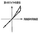
- FIG. 2A is a schematic diagram for explaining the relationship between the bending amount of the bending portion and the displacement of the first wire.
- FIG. 2B is a schematic diagram for explaining the relationship between the bending amount of the bending portion and the displacement of the second wire.
- FIG. 3A is a diagram for explaining a configuration example of the bending operation system according to the first embodiment, particularly a configuration example of a displacement detection unit, and shows a state where the bending unit is bent in a positive bending direction. It is.
- FIG. 1 is a block diagram illustrating a configuration example of the bending operation system according to the first embodiment.
- FIG. 2A is a schematic diagram for explaining the relationship between the bending amount of the bending portion and the displacement of the first wire.
- FIG. 2B is a schematic diagram for explaining the relationship between the bending amount of the bending portion and the displacement of the second wire.
- FIG. 3B is a diagram for explaining a configuration example of the bending operation system according to the first embodiment, particularly a configuration example of the displacement detection unit, and is a diagram illustrating a state where the bending unit is straight.
- FIG. 3C is a diagram for explaining a configuration example of the bending operation system according to the first embodiment, particularly a configuration example of the displacement detection unit, and shows a state where the bending unit is bent in a negative bending direction. It is.
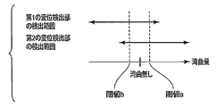
- FIG. 4 is a diagram for explaining an example of the relationship between the bending amount of the bending portion and the detection range of the displacement detection portion.
- FIG. 5A is a diagram for explaining another example of the relationship between the bending amount of the bending portion and the detection range of the displacement detection portion.
- FIG. 5B is a diagram for explaining another example of the relationship between the bending amount of the bending portion and the detection range of the displacement detection portion.
- FIG. 6A is a diagram for describing a configuration example of the bending operation system, in particular, another configuration example of the displacement detection unit, and is a diagram illustrating a state where the bending unit is bent in the positive bending direction.
- FIG. 6B is a diagram for explaining a configuration example of the bending operation system, in particular, another configuration example of the displacement detection unit, and is a diagram illustrating a state where the bending unit is straight.
- FIG. 6A is a diagram for describing a configuration example of the bending operation system, in particular, another configuration example of the displacement detection unit, and is a diagram illustrating a state where the bending unit is bent in the positive bending direction.
- FIG. 6B is a diagram for explaining a configuration example of the bending operation system, in particular, another configuration example of the displacement detection unit, and is a diagram illustrating a state where
- FIG. 6C is a diagram for explaining a configuration example of the bending operation system, in particular, another configuration example of the displacement detection unit, and is a diagram illustrating a state where the bending unit is bent in a negative bending direction.
- FIG. 7 is a flowchart illustrating an example of processing of the calculation unit in the bending motion system according to the first embodiment.
- FIG. 8 illustrates an example of the relationship between the first temporary bending amount, the second temporary bending amount, and the bending amount determined by the calculation unit with respect to the actual bending amount of the bending portion when not according to the first embodiment. It is a schematic diagram for carrying out, and is an enlarged view near the origin.
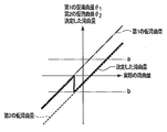
- FIG. 9 is a schematic diagram illustrating an example of the relationship between the first temporary bending amount, the second temporary bending amount, and the bending amount determined by the calculation unit with respect to the actual bending amount of the bending portion according to the first embodiment. is there.
- FIG. 10 is a schematic diagram illustrating an example of the relationship between the first temporary bending amount, the second temporary bending amount, and the bending amount determined by the calculation unit with respect to the actual bending amount of the bending portion according to the first embodiment. There is an enlarged view near the origin.
- FIG. 11 is a flowchart illustrating an example of processing of the calculation unit in the bending motion system according to the modification of the first embodiment.
- FIG. 12A is a flowchart illustrating an example of processing of a calculation unit in the bending motion system according to the second embodiment.
- FIG. 12B is a flowchart illustrating an example of processing of the calculation unit in the bending motion system according to the second embodiment, and is a continuation of FIG. 12A.
- FIG. 13 is a schematic diagram illustrating an example of the relationship between the first temporary bending amount, the second temporary bending amount, and the bending amount determined by the calculation unit with respect to the actual bending amount of the bending portion according to the second embodiment. There is an enlarged view near the origin.
- FIG. 14 is a block diagram illustrating a configuration example of the bending operation system according to the third embodiment.
- FIG. 1 shows a configuration example of a bending operation system 100 according to this embodiment.
- the bending motion system 100 has an elongated tubular portion 110.
- a curved portion 115 is provided in the vicinity of one end portion of the tubular portion 110. Further, the other end of the tubular portion 110 is connected to the grip portion 130.
- a first wire 122 and a second wire 124 are inserted into the tubular portion 110. One end of each of the first wire 122 and the second wire 124 is connected to the vicinity of the bending portion 115. The other ends of the first wire 122 and the second wire 124 are connected to each other by a chain 126 in the grip portion 130.
- a driving unit 132 is provided in the gripping unit 130.
- the drive unit 132 includes a sprocket (not shown) and a knob for rotating the sprocket.
- the sprocket teeth and the chain 126 are engaged with each other.
- the knob rotates, the sprocket also rotates and power is transmitted to the chain 126.
- the first wire 122 and the second wire 124 connected to the chain 126 are integrally displaced in the longitudinal direction, and one wire is pulled and the other wire is fed out. Since one end of the first wire 122 and the second wire 124 is connected to face the vicinity of the bending portion 115, the first wire 122 and the second wire 124 are displaced in the longitudinal direction.
- the bending portion 115 is bent in the first direction and the second direction.
- the first direction and the second direction are opposite directions.
- the bending of the bending portion 115 is defined as 0 with the bending portion 115 being straight, and the upper side in FIG. And the lower side is defined as a negative bending direction.
- the drive unit 132 is composed of a knob and a sprocket, and the knob is manually rotated by the user.
- the present invention is not limited to this, and the drive unit 132 may be configured so that the sprocket is driven by a motor or an actuator.
- the drive unit 132 may be configured to have other drive means such as an actuator for displacing the first wire 122 and the second wire 124.
- the first wire 122 and the second wire 124 do not have to be connected by the chain 126, and the power of the actuator is configured to be transmitted to the first wire and the second wire. Just do it.
- the first wire and the second wire may not be connected so that when one wire is pulled, the other wire can be freely displaced according to the bending of the bending portion 115. It only has to be configured.
- a first displacement detector 136 for detecting the displacement in the longitudinal direction of the first wire 122 and a second displacement for detecting the displacement in the longitudinal direction of the second wire 124.
- a detection unit 138 is provided.
- the first displacement detection unit 136 and the second displacement detection unit 138 in the present embodiment are encoders, for example.
- a first scale is fixed to the first wire 122
- a second scale is fixed to the second wire 124.
- the first displacement detector 136 detects the displacement of the first wire 122 by detecting the displacement of the first scale
- the second displacement detector 138 detects the displacement of the second scale.
- the displacement of the second wire 124 is detected.
- the first displacement detector 136 and the second displacement detector 138 are connected to the calculator 140, respectively.
- the calculation unit 140 calculates the shape of the bending unit 115 based on the outputs from the first displacement detection unit 136 and the second displacement detection unit 138.
- the shape of the bending portion 115 is, for example, an angle formed by tangent lines at both ends of the bending portion 115, that is, an angle formed by a tangent line at the bending start position of the bending portion 115 and a tangent line at the bending end position (hereinafter referred to as a bending amount). Or the curvature of the curved portion 115.
- the amount of bending will be described as an example of the shape of the bending portion 115.
- the calculation unit 140 is provided outside the gripping unit 130, but the calculation unit 140 may be provided inside the gripping unit 130.
- the calculation unit 140 outputs information related to the shape of the bending unit 115.
- FIG. 2A shows the relationship between the displacement of the first wire 122 and the bending amount of the bending portion 115.
- FIG. 2B shows the relationship between the displacement of the second wire 124 and the bending amount of the bending portion 115.
- the displacement of the first wire 122 and the second wire 124 is positive in the direction in which the first wire 122 is pulled and negative in the direction in which the second wire 124 is pulled.
- the bending amount of the bending portion 115 is larger when the second wire 124 is being pulled than when the first wire 122 is being pulled (the bending is The absolute value of the quantity is large).
- the bending is The absolute value of the quantity is large.
- the calculation unit 140 determines the bending amount of the bending portion 115 using both the displacement of the first wire 122 and the displacement of the second wire 124.
- the calculating unit 140 determines the bending amount of the bending portion 115 based on the displacement of the second wire 124, and the bending amount of the bending portion 115 is When negative, the bending amount of the bending portion 115 is determined based on the displacement of the first wire 122.
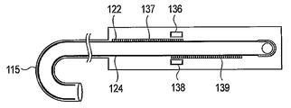
- 3A, 3B, and 3C show configuration examples related to the first displacement detection unit 136 and the second displacement detection unit 138 of the present embodiment.
- 3A schematically illustrates a state in which the bending portion 115 is curved in the positive bending direction
- FIG. 3B schematically illustrates a state in which the bending portion 115 is straight
- FIG. 3C illustrates that the bending portion 115 is negatively curved.
- the state which is curving in a direction is shown typically.
- a first scale 137 that is an encoder scale for the first displacement detector 136 is fixed to the first wire 122, and a second displacement detection is performed on the second wire 124.
- a second scale 139 that is an encoder scale for the portion 138 is fixed.
- the first scale 137 and the second scale 139 are arranged to be biased toward the chain 126 with respect to the first displacement detector 136 and the second displacement detector, respectively. That is, as shown in FIG. 3A, when the first wire 122 is pulled and the bending portion 115 is bent in the positive bending direction, the second scale 139 moves at a position facing the second displacement detection portion 138. To do. Therefore, the second displacement detector 138 measures the displacement of the second wire 124 when the first wire 122 is mainly pulled and the bending portion 115 is bent in the positive bending direction. Further, as shown in FIG.
- the first displacement detector 136 measures the displacement of the first wire 122 when the second wire 124 is mainly pulled and the bending portion 115 is bent in the negative bending direction.
- FIG. 4 shows the relationship of the detection range by the first displacement detector 136 and the first scale 137 with respect to the bending amount of the bending portion 115, and the second displacement detector 138 and the second scale with respect to the bending amount of the bending portion 115.
- 139 shows the relationship of the detection range by 139.
- the first displacement detection unit 136 and the first scale 137 include the entire range of the negative bending direction of the bending unit 115 and a first threshold value described later in the positive bending direction from the state in which the bending unit 115 is not bent. A bending amount in a range including a is detected.
- the second displacement detection unit 138 and the second scale 139 have the entire range of the bending portion 115 in the positive bending direction and the second bending direction described later from the state in which the bending portion 115 is not bent.
- the bending amount in the range including the threshold value b is detected.
- the first threshold value a is a> 0, and the second threshold value b is b ⁇ 0.
- the detection range by the first displacement detection unit 136 and the first scale 137 and the detection range by the second displacement detection unit 138 and the second scale 139 partially overlap.
- the detection range by the first displacement detection unit 136 and the first scale 137 and the detection range by the second displacement detection unit 138 and the second scale 139 are set so as not to overlap. You can also Further, as shown in FIG. 5B, the detection range by the first displacement detection unit 136 and the first scale 137 and the detection range by the second displacement detection unit 138 and the second scale 139 are both curved portions 115. It is also possible to use the entire curved range. In this case, the arrangement of the first scale 137 and the second scale 139 is as shown in FIGS. 6A, 6B, and 6C.
- the first scale 137 and the second scale 139 may interfere with other components.
- the long first scale 137 and the second scale 139 may not be arranged. Therefore, as described with reference to FIGS. 3A, 3B, 3C, and 4, the detection range by the first displacement detector 136 and the first scale 137, the second displacement detector 138, and the second By adjusting the detection range by the scale 139, the first scale 137 and the second scale 139 can be shortened, and the arrangement thereof becomes easy. As a result, the degree of freedom in designing the bending operation system 100 is improved.
- the user operates the driving unit 132 to grip the grip 130 and bend the bending portion 115 of the tubular portion 110 by a desired angle. That is, the user rotates the knob of the drive unit 132.
- the sprocket is rotated by rotating the knob, the chain 126 meshing with the sprocket is displaced.
- the first wire 122 and the second wire 124 are displaced.
- the bending portion 115 of the tubular portion 110 is bent.
- the first scale 137 fixed to the first wire 122 and the second scale 139 fixed to the second wire 124 are displaced.
- the first displacement detection unit 136 converts the displacement of the first scale 137 into an electric signal and outputs it to the calculation unit 140.
- the displacement of the first scale 137 that is, the displacement of the first wire 122 is defined as a first displacement Enc1.
- the second displacement detector 138 converts the displacement of the second scale 139 into an electrical signal and outputs the electrical signal to the calculator 140.
- the displacement of the second scale 139, that is, the displacement of the second wire 124 is referred to as a second displacement Enc2.
- step S1 the calculation unit 140 acquires the first displacement Enc1 from the first displacement detection unit 136, and acquires the second displacement Enc2 from the second displacement detection unit 138.
- step S ⁇ b> 2 the calculation unit 140 calculates a first temporary bending amount ⁇ 1 that is a temporary value of the bending amount of the bending portion 115 from the following equation (1) based on the first displacement Enc1.
- ⁇ 1 ⁇ 1 ⁇ Enc1 (1)
- the calculation unit 140 calculates the second temporary bending amount ⁇ 2 that is a temporary value of the bending amount of the bending portion 115 from the following equation (2) based on the second displacement Enc2.
- ⁇ 2 ⁇ 2 ⁇ Enc2 (2)
- ⁇ 1 and ⁇ 2 are predetermined constants.
- the constant ⁇ 1 is determined in advance based on the relationship between the displacement of the first wire 122 and the bending amount of the bending portion 115 when the bending portion 115 is bent in the negative bending direction.
- the constant ⁇ 2 is determined based on the relationship between the displacement of the second wire 124 and the bending amount of the bending portion 115 when the bending portion 115 is bent in the positive bending direction in advance. deep. Since constant ⁇ 1 and constant ⁇ 2 are generally substantially equal, one of constant ⁇ 1 and constant ⁇ 2 may be obtained and the value may be used as both constant ⁇ 1 and constant ⁇ 2.
- the relationship between the bending amount of the bending portion 115 and the first temporary bending amount ⁇ 1 or the second temporary bending amount ⁇ 2 is a simple proportional relationship. Any expression such as a higher-order expression may be used as long as the expression expresses these relationships sufficiently well.
- the relationship between the displacement of the second wire 124 and the bending amount of the bending portion 115 when the portion 115 is bent in the positive bending direction may be obtained in advance, and these relationships may be prepared as a table.
- the calculating unit 140 based on the table, from a first displacement Enc1 determining a first temporary bending amount theta 1, determines a second temporary bending amount theta 2 from the second displacement Enc2.
- the first temporary bending amount ⁇ 1 when bending in the negative bending direction, the first temporary bending amount ⁇ 1 is obtained, and when bending in the positive bending direction, the second temporary bending amount ⁇ 2 is obtained as the final bending.
- the method of setting the amount is such that when the actual bending amount of the bending portion 115 is 0 (straight), the first temporary bending amount ⁇ 1 and the second temporary bending amount ⁇ 2 coincide with each other or there is no problem in use. The difference is sufficient. However, as shown in FIG. 8, when the actual bending amount of the bending portion 115 is 0, the first temporary bending amount ⁇ 1 and the second temporary bending amount are simultaneously generated due to the structures of the tubular portion 110 and the grip portion 130.
- the bending amount not necessarily a bending amount theta 2 and becomes zero, there may be a slight deviation occurs.
- the selection of the first temporary bending amount ⁇ 1 and the second temporary bending amount ⁇ 2 is changed as a final bending amount on the condition that the bending amount is simply 0 or more, the bending amount The value of the amount may be skipped, or the change may be opposite to the actual bending direction. Therefore, the user feels uncomfortable with the change in the calculated amount of bending with respect to the amount of rotation of the operation knob. Therefore, the following algorithm is used to perform calculation so that the calculated amount of bending does not skip or a change opposite to the actual bending direction does not occur.
- Calculator 140 in step S4 on the basis of the temporary bending amount theta 2 of the first temporary bending amount theta 1 and the second, using a conversion equation selected in step S3, determines the bending amount of the bending portion 115. That is, as shown in Table 1, when ⁇ 1 ⁇ a and ⁇ 2 ⁇ a, or when b ⁇ 1 ⁇ a and ⁇ 2 ⁇ a, the second temporary bending amount ⁇ 2 is set to the bending portion 115. The amount of bending.
- the first The weighted average using the temporary bending amount ⁇ 1 and the second temporary bending amount ⁇ 2 is defined as the bending amount of the bending portion 115.
- the first temporary bending amount ⁇ 1 is set as the bending amount of the bending portion 115.
- the following expression (3) is used as an expression for obtaining a weighted average representing the bending amount ⁇ of the bending portion 115.
- ⁇ f ( ⁇ 1 , ⁇ 2 ) ⁇ ⁇ 1 + (1 ⁇ f ( ⁇ 1 , ⁇ 2 )) ⁇ ⁇ 2 (3)
- the following formula (4) can be used.
- the first provisional bending amount ⁇ 1 and the second provisional bending amount ⁇ 2 are used for the function related to the weight, but the same applies even if the first displacement Enc1 and the second displacement Enc2 are used. It is.
- the above formula (3) is represented by the following formula (5), for example.
- FIG. 9 is a schematic diagram showing the relationship between the first temporary bending amount ⁇ 1 , the second temporary bending amount ⁇ 2 , and the bending amount of the bending portion 115 determined by the calculation unit 140 with respect to the actual bending amount of the bending portion 115. And shown in FIG. FIG. 10 is a part of an enlarged view near the origin of FIG.
- the alternate long and short dash line indicates the first temporary bending amount ⁇ 1
- the broken line indicates the second temporary bending amount ⁇ 2
- the solid line indicates the bending amount of the bending portion 115 determined by the calculation unit 140.
- the completely coincident lines are actually drawn slightly shifted for easy viewing.
- the calculation unit 140 bends the first temporary bending amount ⁇ 1 based on the output of the first displacement detection unit 136 when the bending unit 115 is generally bent in the negative bending direction.
- the second temporary bending amount ⁇ 2 based on the output of the second displacement detection unit 138 is used as the bending amount of the bending portion 115.
- the bending average of the bending portion 115 is calculated by calculating a weighted average based on the first temporary bending amount ⁇ 1 and the second temporary bending amount ⁇ 2. Amount.
- step S5 the calculation unit 140 outputs the determined bending amount of the bending portion 115.
- the bending operation system 100 and other devices may display a figure or a graph representing the determined bending amount value or bending amount on a display or the like and present it to the user, for example. Further, based on the output bending amount, the bending operation system 100 and other devices may use the output bending amount for arbitrary control.
- step S ⁇ b> 6 the calculation unit 140 determines whether or not the end of the bending amount calculation process is instructed. If no termination instruction has been given, the process returns to step S1. On the other hand, if an end instruction is given, the series of processing ends.
- the bending amount of the bending portion 115 can be determined with high accuracy by determining the bending amount of the bending portion 115 as described above. That is, when the bending amount of the bending portion 115 is calculated using only one of the first displacement Enc1 of the first wire 122 and the second displacement Enc2 of the second wire 124, for example, it is derived from hysteresis. There is a possibility that the bending amount cannot be calculated because the bending amount and the displacement of the first wire 122 or the second wire 124 do not correspond to each other, or an error included in the calculated bending amount may increase. .
- the amount of bending of the bending portion 115 can be determined with high accuracy by using both the first displacement Enc1 and the second displacement Enc2. By detecting the amount of bending with high accuracy, for example, the operability of the bending portion 115 by the user can be improved, or the quality of control of the system can be improved.
- the weighted average of the temporary bending amount of the first theta 1 and based on the second and temporary bending amount theta 2 the by calculating can be coupled temporary bending amount of the 1 theta 1 and the deviation between the second temporary bending amount theta 2 smoothly. That is, for example, when the first temporary bending amount ⁇ 1 is simply negative, the first temporary bending amount ⁇ 1 is used as the bending amount of the bending portion 115, and when the first temporary bending amount ⁇ 1 is positive, the first temporary bending amount ⁇ 1 is the first amount.
- the actual bending amount of the bending portion 115 and the bending amount determined by the calculation unit 140 have a relationship as shown in FIG. Become.
- the calculation is performed even though the actual amount of bending continuously increases.
- the value of the amount of curvature determined by the portion 140 may decrease discontinuously, that is, a discontinuous reverse phenomenon may occur.
- Such discontinuity and the reversal phenomenon of the change in the amount of bending give the user a sense of incongruity when the amount of bending is presented to the user, for example.
- the bending amount determined by the calculation unit 140 is smoothly and continuously changed as described above, so that the user does not feel uncomfortable.
- the first temporary bending amount ⁇ 1 and the second temporary bending amount ⁇ 2 coincide with each other, or in use. If only varying degrees no problem does not exist, for example, when the bending amount is negative the bending amount of the first temporary bending amount theta 1 the bending portion 115, temporary bending amount of the second when the bending amount is positive theta 2 It is also possible to use a method for determining the amount of bending so that is the amount of bending of the bending portion 115. In this case, as shown in FIG.
- the first scale 137 has a length capable of measuring only a range in which the bending amount is negative
- the second scale 139 has a length capable of measuring only a range in which the bending amount is negative. It may be designed to do. As a result, the first scale 137 and the second scale 139 can be further shortened, and the degree of freedom in designing the bending operation system 100 is further improved.
- the above formulas (3) to (7) described in the present embodiment are merely examples, and other functions may be used.
- it includes between the first threshold value a and the second threshold value b, which well represents the relationship between the first temporary bending amount ⁇ 1 or the second temporary bending amount ⁇ 2 and the actual bending amount of the bending portion 115. It is conceivable to use other consecutive functions.
- the first displacement detection unit 136 and the second displacement detection unit 138 are arranged in the gripping unit 130, thereby reducing the size of the distal end side of the tubular unit 110 in which the bending unit 115 is arranged, while reducing the first side.
- the displacement of the first wire 122 and the second wire 124 can be detected.
- positioned can implement
- the first scale 137 and the second scale 139 are required for the calculation unit 140 to determine the bending amount.
- the first wire 122 and the second wire 124 are arranged only in the moving range. Accordingly, the first scale 137 and the second scale 139 can be shortened, and the degree of freedom in designing the bending operation system 100 is improved.
- the first wire 122 and the second wire 124 are connected by a chain 126, and the first wire 122 and the second wire 124 are integrally displaced in the longitudinal direction. In this way, it is not necessary to drive the first wire 122 and the second wire 124 separately.
- the first wire 122 and the second wire 124 can be displaced by simply rotating the sprocket meshed with the chain 126 using the knob, that is, the bending portion 115 can be bent.
- the user drives by a motor or the like instead of rotating the knob, it is not necessary to provide a motor for each of the first wire 122 and the second wire 124, and only one motor is provided for the sprocket. A system can be realized.
- the tubular portion 110 functions as a tubular portion having an elongated shape.
- the bending portion 115 can be bent within a predetermined movable range and functions as a bending portion included in the tubular portion.
- the first wire 122 is connected to the tubular portion at one end and functions as a first linear member that transmits power for bending the bending portion in the first direction by being displaced in the longitudinal direction.
- the second wire 124 has one end connected to the tubular portion and is displaced in the longitudinal direction, whereby the second wire 124 transmits power for bending the bending portion in a second direction that is opposite to the first direction. Functions as a linear member.
- the drive unit 132 functions as a drive unit that displaces the first linear member and the second linear member.
- the first displacement detector 136 functions as a first displacement detector that acquires the displacement of the first linear member as the first displacement.
- the second displacement detector 138 functions as a second displacement detector that acquires the displacement of the second linear member as the second displacement.
- the calculation unit 140 functions as a calculation unit that calculates the operation support information using one or both of the first displacement and the second displacement based on the state of the bending portion.
- the amount of bending functions as operation support information. For example, a position where the curved portion is straight functions as a reference position.
- the first threshold value a functions as a first bending threshold value that represents a state in which the bending portion is bent by a predetermined amount in the first direction from the reference position.
- the second threshold value b is the second threshold value b from the reference position. It functions as a second bending threshold value that represents a state of bending a predetermined amount in the direction of 2.
- the chain 126 functions as a connecting member that connects the other end of the first linear member and the other end of the second linear member.
- the first wire 122 and the second wire 124 are exemplified as the linear members, but the present invention is not limited thereto.
- the material is not limited to metal, and may be a resin or other polymer compound, and may be a linear member that transmits power by moving in the longitudinal direction.
- an encoder is used as an example of the displacement detection unit, but the present invention is not limited to this. As long as the displacement between the first wire 122 and the second wire 124 can be detected, any detector may be used.
- the tubular portion 110 is in a straight state as a reference position.
- the calculation unit 140 outputs the bending amount of the bending unit 115.
- the calculation unit 140 outputs the drive amount of the drive unit 132.
- the drive amount is an operation amount of the knob operated by the user.
- the first displacement Enc1 of the first wire 122 and the driving amount of the knob are similar to the relationship between the first displacement Enc1 and the bending amount of the bending portion 115 in the case of the first embodiment.
- the relationship is acquired in advance.
- the relationship between the second displacement Enc2 of the second wire 124 and the driving amount of the knob is acquired in advance.
- the calculation unit 140 can obtain the knob driving amount based on the first displacement Enc1 and the second displacement Enc2 using these relationships.
- step S21 the calculation unit 140 acquires the first displacement Enc1 from the first displacement detection unit 136 and acquires the second displacement Enc2 from the second displacement detection unit 138.
- step S22 the calculation unit 140 uses the relationship between the first displacement Enc1 and the knob driving amount based on the first displacement, and the first temporary driving amount D1 that is the temporary driving amount of the knob. Is calculated. Further, the calculation unit 140 uses the relationship between the second displacement Enc2 and the knob driving amount described above based on the second displacement Enc2, and the second temporary driving amount D2 that is a temporary driving amount of the knob. Is calculated.
- step S23 the calculation unit 140 refers to the following table 2 similar to that shown in, for example, Table 1 based on the first temporary drive amount D1 and the second temporary drive amount D2, in the first embodiment. As in the case of, the conversion formula is selected.
- step S24 the calculation unit 140 determines the drive amount D of the drive unit 132 based on the first temporary drive amount D1 and the second temporary drive amount D2. For example, when the first temporary drive amount D1 appropriately represents the drive amount D, the first temporary drive amount D1 is the drive amount D, and the second temporary drive amount D2 appropriately represents the drive amount D. In this case, the second temporary drive amount D2 is set as the drive amount D, and the weighted average of the first temporary drive amount D1 and the second temporary drive amount D2 is set as the drive amount D under the condition between them.
- step S25 the calculation unit 140 outputs the determined drive amount D.
- step S ⁇ b> 26 the calculation unit 140 determines whether an instruction to end the process has been input. If no end instruction has been input, the process returns to step S21. If an end instruction has been input, the process is terminated.
- the driving amount D of the driving unit 132 is output from the calculation unit 140.
- the driving amount D By presenting the driving amount D to the user, for example, the user's operation can be supported, or the driving amount D can be used for system control. Further, based on the first temporary drive amount D1 and the second temporary drive amount D2, a highly accurate drive amount can be calculated by using a value closer to the actual drive amount or taking a weighted average. It can be carried out.
- the user rotates the knob of the drive unit 132.
- the drive unit 132 may include an actuator or a motor.
- the drive amount functions as operation support information.
- various types of information can be applied to the operation support information.
- the displacement itself of the first wire 122 and the second wire 124 can be the operation support information, and the first wire 122 of the wire such as the shape of the bending portion 115, the traction force of the wire, and the stress applied to the bending portion 115.
- the value calculated based on the displacement of the second wire 124 functions as operation support information.
- the calculation unit 140 determines the bending amount of the bending portion 115 based on the combination of the value of the first temporary bending amount ⁇ 1 and the value of the second temporary bending amount ⁇ 2. Yes. On the other hand, in the present embodiment, the calculation unit 140 selects either the value of the first temporary bending amount ⁇ 1 or the second temporary bending amount ⁇ 2 as the bending amount of the bending portion 115. .
- the calculation unit 140 changes the first bending amount based on the first temporary bending amount ⁇ 1 to the first determining state based on the second temporary bending amount ⁇ 2 .
- difference temporary bending amount theta 1 and the second temporary bending amount theta 2 is a condition to be a predetermined value or less.
- step S ⁇ b> 31 the calculation unit 140 acquires the first displacement Enc1 from the first displacement detection unit 136 and acquires the second displacement Enc2 from the second displacement detection unit 138.
- step S32 the first calculating the temporary bending amount theta 1 based on the first displacement Enc1, a second for calculating the temporary bending amount theta 2 based on the second displacement Enc2.
- step S33 the calculation unit 140 determines whether or not the first temporary bending amount ⁇ 1 is smaller than zero. When the first temporary bending amount theta 1 is less than 0, the process proceeds to step S34.
- step S ⁇ b> 34 the calculation unit 140 determines the first temporary bending amount ⁇ 1 as the bending amount of the bending portion 115.
- Step calculator 140 step S35 substitutes 1 into the variable FLAG representing whether the current amount of curvature of the decision is based on a second temporary bending amount theta 2 or based on the first temporary bending amount theta 1. Thereafter, the process proceeds to step S38.
- step S33 if there is no first temporary bending amount theta 1 is less than 0, the process proceeds to step S36.
- step S ⁇ b> 36 the calculation unit 140 determines the second temporary bending amount ⁇ 2 as the bending amount of the bending portion 115.
- step S37 the calculation unit 140 assigns 2 to the variable FLAG. Thereafter, the process proceeds to step S38.
- step S ⁇ b> 38 the calculation unit 140 outputs the determined bending amount of the bending portion 115.
- step S39 the calculation unit 140 acquires the first displacement Enc1 from the first displacement detection unit 136, and acquires the second displacement Enc2 from the second displacement detection unit 138.
- step S40 the first calculating the temporary bending amount theta 1 based on the first displacement Enc1, a second for calculating the temporary bending amount theta 2 based on the second displacement Enc2.
- Step S41 140 a first provisional bending amount theta 1 and the second temporary bending amount theta 2, the first temporary bending amount theta 1 and the second temporary bending amount theta 2 which acquired this time acquired previously And calculating whether the bending amount of the bending portion 115 is increasing or decreasing, that is, whether the bending portion 115 is bending in the positive bending direction or in the negative bending direction. To do.
- Step S42 140 a first temporary bending amount theta 1 is less than the larger first threshold value a than the second threshold value b, and the second temporary bending amount theta 2 first larger than the second threshold value b It is determined whether or not the threshold value is smaller than 1.
- the process proceeds to step S43.
- the process proceeds to step S50.
- Step calculating unit 140 in S45 determines the bending amount of the bending portion 115 to the second temporary bending amount theta 2.
- step S46 the calculation unit 140 substitutes 2 for the variable FLAG. Thereafter, the process proceeds to step 55.
- step S48 the condition for determination in step S47 is satisfied
- step S50 the condition for determination in step S48
- step S49 the calculation unit 140 substitutes 1 for the variable FLAG. Thereafter, the process proceeds to step 55.
- step S50 the calculation unit 140 determines whether or not the variable FLAG is 1. If the variable FLAG is 1, i.e., when the bending amount of the bending portion 115 has first and temporary bending amount theta 1, the process proceeds to step S51. Calculator 140 in step S51 determines the bending amount of the bending portion 115 to the first temporary bending amount theta 1. In step S52, the calculation unit 140 substitutes 1 for the variable FLAG. Thereafter, the process proceeds to step 55.
- step S50 i.e., the variable FLAG is when a and bending amount of the bending portion 115 a 2 is a second temporary bending amount theta 2
- the process proceeds to step S53.
- Step calculating unit 140 in and S53 it determines the bending amount of the bending portion 115 to the second temporary bending amount theta 2.
- step S54 the calculation unit 140 substitutes 2 for the variable FLAG. Thereafter, the process proceeds to step 55.
- step S55 the calculation unit 140 outputs the determined bending amount of the bending portion 115.
- step S56 the calculation unit 140 determines whether an instruction to end the process is input. If no end instruction has been input, the process returns to step S39, and if an end instruction has been input, the process ends.
- the relationship between the first temporary bending amount ⁇ 1 , the second temporary bending amount ⁇ 2 and the bending amount of the bending portion 115 determined by the calculation unit 140 with respect to the actual bending amount of the bending portion 115 is expressed.
- the schematic diagram is as shown in FIG. FIG. 13 shows an example when the amount of bending changes from a negative direction to a positive direction.
- the first temporary bending amount theta 1 is less than the larger first threshold value a than the second threshold value b, and the second temporary bending amount theta 2 first larger than the second threshold value b 1 smaller than the threshold value a (Yes in step S42), the difference between the first temporary bending amount theta 1 and the second temporary bending amount theta 2 is smaller than the predetermined set value (Yes in step S43), the amount of curvature increases and has, and when the current bending amount has become a temporary bending amount theta 1 of the first (Yes in step S44), the amount of curvature, the the state determined based on the first temporary bending amount theta 1 2 is changed to a state determined based on the temporary bending amount ⁇ 2 of 2 .
- the first temporary bending amount ⁇ 1 is larger than the second threshold value b and smaller than the first threshold value a
- the second temporary bending amount ⁇ 2 is larger than the second threshold value b and larger than the first threshold value a.
- the discontinuity of the bending amount determined by the calculation unit 140 can be set small enough to be ignored according to the set value in step S43.
- the operability of the bending portion 115 by the user can be improved, and the quality of control of the system can be improved.
- a third embodiment will be described.
- differences from the first embodiment will be described, and the same portions will be denoted by the same reference numerals and description thereof will be omitted.
- the bending operation can be performed in two directions in which the bending portion 115 is orthogonal. That is, it can bend in the first and second directions, and further bend in the third and fourth directions, which are directions orthogonal to the first and second directions.
- the first and second directions are opposite directions
- the third and fourth directions are opposite directions.
- the bending portion 115 can be bent not only in two orthogonal directions but also in all directions by a combination of bending operations in two orthogonal directions. However, it can be bent only in two orthogonal bending directions. In the third embodiment, the bending operation can be performed in two orthogonal directions, but the two directions may not be orthogonal.
- FIG. 14 shows an outline of a configuration example of the bending operation system 200 according to the present embodiment.
- the bending operation system 200 includes the following in addition to the bending operation system 100 according to the first embodiment. That is, the curves in the third and fourth directions orthogonal to the curves in the first and second directions curved by the first wire 122 and the second wire 124 are provided.
- the bending operation system 200 includes a third wire 222 and a fourth wire 224 for bending the bending portion 115 in the second direction.
- the third wire 222 and the fourth wire 224 the first wire 122 and the second wire 124 are connected by a chain 126 (hereinafter, this chain is referred to as the first chain 126).
- the second chain 226 meshes with a second sprocket provided in the drive unit 132, and the second sprocket is connected to the second knob.
- the second knob of the drive unit 132 When the user rotates the second knob of the drive unit 132, the second sprocket is rotated, and the second chain 226 is displaced.
- the third wire 222 and the fourth wire 224 With the displacement of the second chain 226, the third wire 222 and the fourth wire 224 are displaced, and the bending portion 115 is bent in the third or fourth direction.
- the third wire 222, the fourth wire 224, and the second chain 226 correspond to the first wire 122, the second wire 124, and the first chain 126, respectively, and are similar to them.
- the bending operation system 200 includes a third displacement detector 236 for detecting the displacement of the third wire 222.
- the third displacement detector 236 is an encoder, for example, and an encoder scale (not shown) is fixed to the third wire 222.
- the third displacement detector 236 outputs data relating to the displacement of the third wire 222 to the calculator 140.
- the bending motion system 200 includes a fourth displacement detector 238 for detecting the displacement of the fourth wire 224.
- the fourth displacement detector 238 is, for example, an encoder, and an encoder scale (not shown) is fixed to the fourth wire 224.
- the fourth displacement detector 238 outputs data related to the displacement of the fourth wire 224 to the calculator 140.
- the third displacement detector 236 and the fourth displacement detector 238 correspond to the first displacement detector 136 and the second displacement detector 138, respectively, and function in the same manner.
- the calculation unit 140 calculates the amount of bending in the third and fourth directions in the same manner as in the first embodiment described with reference to FIGS. 7 to 10. Calculation is based on the output of the displacement detector 238. According to the present embodiment, the bending of the bending portion 115 and the determination of the bending amount function in the same manner as in the first embodiment, and the same effect can be obtained.
- the bending portion 115 is freely bent in the first and second directions and the third and fourth directions, so that the bending portion 115 is bent in any direction with respect to directions other than the twist with respect to the bending portion 115.
- the portion 115 can be curved.
- the third wire 222 has one end connected to the tubular portion and is displaced in the longitudinal direction, whereby the bending portion is bent in a third direction different from the first direction and the second direction. It functions as a third linear member that transmits the power to be moved.
- the fourth wire 224 has a first end connected to the tubular portion and is displaced in the longitudinal direction to transmit power for bending the bending portion in a fourth direction that is opposite to the third direction. It functions as a linear member.
- the third displacement detector 236 functions as a third displacement detector that acquires the displacement of the third linear member as the third displacement.
- the fourth displacement detector 238 functions as a fourth displacement detector that acquires the displacement of the fourth linear member as the fourth displacement.
- the present invention is not limited to the above-described embodiment as it is, and can be embodied by modifying constituent elements without departing from the scope of the invention in the implementation stage.
- various inventions can be formed by appropriately combining a plurality of components disclosed in the embodiment. For example, even if some constituent elements are deleted from all the constituent elements shown in the embodiment, the problem described in the column of problems to be solved by the invention can be solved and the effect of the invention can be obtained. The configuration in which this component is deleted can also be extracted as an invention.
- constituent elements over different embodiments may be appropriately combined.
Landscapes
- Health & Medical Sciences (AREA)
- Life Sciences & Earth Sciences (AREA)
- Surgery (AREA)
- Physics & Mathematics (AREA)
- Engineering & Computer Science (AREA)
- Optics & Photonics (AREA)
- Biomedical Technology (AREA)
- Veterinary Medicine (AREA)
- Pathology (AREA)
- Radiology & Medical Imaging (AREA)
- Biophysics (AREA)
- Nuclear Medicine, Radiotherapy & Molecular Imaging (AREA)
- Public Health (AREA)
- Heart & Thoracic Surgery (AREA)
- Medical Informatics (AREA)
- Molecular Biology (AREA)
- Animal Behavior & Ethology (AREA)
- General Health & Medical Sciences (AREA)
- General Engineering & Computer Science (AREA)
- Astronomy & Astrophysics (AREA)
- General Physics & Mathematics (AREA)
- Signal Processing (AREA)
- Mechanical Engineering (AREA)
- Instruments For Viewing The Inside Of Hollow Bodies (AREA)
- Endoscopes (AREA)
- Investigating Strength Of Materials By Application Of Mechanical Stress (AREA)
Abstract
湾曲動作システム(100)は、湾曲部(115)を有する管状部(110)と、前記湾曲部を湾曲させる第1の線状部材(122)及び第2の線状部材(124)と、前記第1の線状部材及び前記第2の線状部材を変位させる駆動部(132)とを含む。湾曲動作システムは、前記第1の線状部材の変位を第1の変位として取得する第1の変位検出部(136)と、前記第2の線状部材の変位を第2の変位として取得する第2の変位検出部(138)と、前記湾曲部の状態に基づいて前記第1の変位と前記第2の変位とのうち一方又は両方を用いて操作支援情報を算出する算出部(140)とをさらに含む。
Description
本発明は、湾曲動作システムに関する。
例えば内視鏡やマニピュレータ等の管状部を備えた装置には、湾曲操作が可能な湾曲部を有するものがある。このような操作可能な湾曲部を持つ内視鏡やマニピュレータには、湾曲部にワイヤが接続されており、そのワイヤを牽引することで湾曲部が湾曲するように構成されているものがある。例えば日本国特開昭61-087530号公報には、湾曲部の近傍に一方の端部が接続された2本のワイヤが設けられており、他方の端部が固定された操作部のドラムによってこの2本のワイヤを変位させ湾曲部を湾曲させる内視鏡に係る技術が開示されている。
日本国特開昭61-087530号公報に開示されているような内視鏡やマニピュレータにおいて、操作性を向上させるための操作支援情報を取得することが考えられる。例えば、湾曲部の形状を示す湾曲量や操作部の操作量を操作支援情報として取得することが考えられる。
操作支援情報を取得するために、例えば湾曲部に角度センサ等を設置して、湾曲部の湾曲量を計測する手法がある。しかしながら、湾曲部に配置する角度センサやその角度センサのための配線により、湾曲部は大きくなる。例えばこの湾曲部を備えた管状部が狭い管等に挿入されることが想定される場合、湾曲部の小型化が要求される。これに対して湾曲部に角度センサ等を配置することは、管状部の小型化の支障となる。
一方、湾曲部を駆動するためのワイヤの変位をエンコーダ等で取得し、その変位に基づいて例えば湾曲部の湾曲量といった操作支援情報を算出することが考えられる。しかしながら、ワイヤの変位と例えば湾曲部の湾曲量とが1対1の対応関係を有しないことがある。その場合、ワイヤの変位と湾曲部の湾曲量とが1対1に対応する関数に基づいて、ワイヤの変位から湾曲量を求めると、求まる湾曲量が実際の湾曲量と異なる恐れがある。
そこで本発明は、管状部を小型化しつつ、精度のよい操作支援情報を算出することができる湾曲動作システムを提供することを目的とする。
前記目的を果たすため、本発明の一態様によれば、湾曲動作システムは、細長形状を有する管状部と、所定の可動範囲で湾曲でき、前記管状部に含まれる湾曲部と、一端が前記管状部に接続され、長手方向に変位させられることで前記湾曲部を第1の方向に湾曲させる動力を伝達する第1の線状部材と、一端が前記管状部に接続され、長手方向に変位させられることで前記湾曲部を前記第1の方向と逆方向である第2の方向に湾曲させる動力を伝達する第2の線状部材と、前記第1の線状部材と前記第2の線状部材とを変位させる駆動部と、前記第1の線状部材の変位を第1の変位として取得する第1の変位検出部と、前記第2の線状部材の変位を第2の変位として取得する第2の変位検出部と、前記湾曲部の状態に基づいて前記第1の変位と前記第2の変位とのうち一方又は両方を用いて操作支援情報を算出する算出部と、を具備することを特徴とする。
本発明によれば、湾曲部の状態に基づいて第1の変位と第2の変位とのうち一方又は両方を用いて操作支援情報を算出するので、管状部を小型化しつつ精度のよい操作支援情報を算出することができる湾曲動作システムを提供できる。
[第1の実施形態]
本発明の第1の実施形態について図面を参照して説明する。図1に本実施形態に係る湾曲動作システム100の構成例を示す。湾曲動作システム100は、細長い管状部110を有する。管状部110の一方の端部の近傍には、湾曲部115が設けられている。また、管状部110の他方の端部は、把持部130に接続されている。管状部110の内部には、第1のワイヤ122と第2のワイヤ124とが挿通されている。第1のワイヤ122と第2のワイヤ124との一端は、それぞれ湾曲部115の近傍に接続されている。第1のワイヤ122と第2のワイヤ124との他端は、把持部130内において、互いにチェーン126で連結されている。
本発明の第1の実施形態について図面を参照して説明する。図1に本実施形態に係る湾曲動作システム100の構成例を示す。湾曲動作システム100は、細長い管状部110を有する。管状部110の一方の端部の近傍には、湾曲部115が設けられている。また、管状部110の他方の端部は、把持部130に接続されている。管状部110の内部には、第1のワイヤ122と第2のワイヤ124とが挿通されている。第1のワイヤ122と第2のワイヤ124との一端は、それぞれ湾曲部115の近傍に接続されている。第1のワイヤ122と第2のワイヤ124との他端は、把持部130内において、互いにチェーン126で連結されている。
把持部130内には、駆動部132が設けられている。駆動部132は、図示しないスプロケットと、スプロケットを回転させるためのノブとを有する。スプロケットの歯とチェーン126とは噛み合っている。ノブが回転するとスプロケットも回転し、チェーン126に動力が伝達される。その結果、チェーン126に連結されている第1のワイヤ122と第2のワイヤ124とは、一体として長手方向に変位し、一方のワイヤが牽引され他方のワイヤが繰り出される。第1のワイヤ122と第2のワイヤ124との一端は湾曲部115の近傍に対向して接続されているので、第1のワイヤ122と第2のワイヤ124とが長手方向に変位することで、湾曲部115は第1の方向と、第2の方向に湾曲する。第1の方向と第2の方向は逆方向であり、ここでは説明のため、湾曲部115の湾曲を、湾曲部115が真直の状態を基準位置として0と定義し、図1における上側を正の湾曲方向と、下側を負の湾曲方向と定義する。第1のワイヤ122を牽引したとき湾曲部115は正の方向に湾曲し、第2のワイヤ124を牽引したとき湾曲部115は負の方向に湾曲する。
本実施形態では、駆動部132をノブとスプロケットとから構成されており、ユーザによってノブが手動で回転させられるものとしている。しかしながらこれに限らず、スプロケットはモータやアクチュエータによって駆動されるように駆動部132を構成してもよい。また、第1のワイヤ122と第2のワイヤ124とを変位させるアクチュエータ等、他の駆動手段を有する様に駆動部132を構成してもよい。この場合、第1のワイヤ122と第2のワイヤ124とはチェーン126で連結されていなくてもよく、アクチュエータの動力が第1のワイヤと第2のワイヤとに伝達されるように構成されていればよい。また、第1のワイヤと第2のワイヤとは、連結されていなくてもよく、一方のワイヤが牽引されているときに他方のワイヤが湾曲部115の湾曲に応じて自由に変位できるように構成されていればよい。
把持部130内には、第1のワイヤ122の長手方向の変位を検出するための第1の変位検出部136と、第2のワイヤ124の長手方向の変位を検出するための第2の変位検出部138とが設けられている。本実施形態における第1の変位検出部136と第2の変位検出部138とは、例えばエンコーダである。後述するように、第1のワイヤ122には第1のスケールが固定されており、第2のワイヤ124には第2のスケールが固定されている。第1の変位検出部136は、第1のスケールの変位を検出することで第1のワイヤ122の変位を検出し、第2の変位検出部138は、第2のスケールの変位を検出することで第2のワイヤ124の変位を検出する。
第1の変位検出部136と第2の変位検出部138とは、それぞれ算出部140に接続されている。算出部140は、第1の変位検出部136と第2の変位検出部138との出力に基づいて、湾曲部115の形状を算出する。ここで、湾曲部115の形状とは、例えば湾曲部115の両端における接線がなす角、すなわち、湾曲部115の湾曲開始位置における接線と湾曲終了位置における接線とがなす角(以下、湾曲量と称する)や、湾曲部115の曲率を意味する。本実施形態では、湾曲部115の形状として湾曲量を例に挙げて説明する。湾曲部の形状として、湾曲部115の曲率や、その他の形状を表す表現を用いても以下の説明は同様である。なお、図1に示す本実施形態に係る湾曲動作システム100では、算出部140は把持部130の外部に設けられているが、算出部140は、把持部130の内部に設けられてもよい。算出部140は、湾曲部115の形状に係る情報を出力する。
第1のワイヤ122の変位と、湾曲部115の湾曲量との関係を図2Aに示す。また、第2のワイヤ124の変位と、湾曲部115の湾曲量との関係を図2Bに示す。ここで、第1のワイヤ122及び第2のワイヤ124の変位は、第1のワイヤ122が牽引される方向を正とし、第2のワイヤ124が牽引される方向を負とする。
図2Aに示すように、第1のワイヤ122の変位が正の場合において、駆動部132によって第1のワイヤ122が牽引されているとき、すなわち、第1のワイヤ122の変位が増加しているとき(変位の絶対値、すなわち、変位量が増加しているとき)と、第2のワイヤ124が牽引されているとき、すなわち、第1のワイヤ122の変位が減少しているとき(変位量が減少しているとき)とで第1のワイヤ122の変位と湾曲部115の湾曲量との関係が一致しない。すなわち、ヒステリシス現象が認められる。例えば、第1のワイヤ122の変位が同じでも、第1のワイヤ122が牽引されているときよりも第2のワイヤ124が牽引されているときの方が湾曲部115の湾曲量は大きい(湾曲量の絶対値は大きい)。一方、図2Aに示すように、第1のワイヤ122の変位が負の場合において、このようなヒステリシスは認められない。
同様に、図2Bに示すように、第2のワイヤ124の変位が負の場合において、駆動部132によって第2のワイヤ124が牽引されているとき、すなわち、第2のワイヤ124の変位が減少しているとき(変位量が増加しているとき)と、第1のワイヤ122が牽引されているとき、すなわち、第2のワイヤ124の変位が増加しているとき(変位量が減少しているとき)とで第2のワイヤ124の変位と湾曲部115の湾曲との関係が一致しない。すなわち、ヒステリシス現象が認められる。例えば、第2のワイヤ124の変位が同じでも、第2のワイヤ124が牽引されているときよりも第1のワイヤ122が牽引されているときの方が湾曲部115の湾曲量は小さい(湾曲量の絶対値は大きい)。一方、図2Bに示すように、第2のワイヤ124の変位が正の場合において、このようなヒステリシスは認められない。
このように、第1のワイヤ122の変位又は第2のワイヤ124の変位の一方のみを用いて、湾曲部115の湾曲量を決定しようとすると、上記のヒステリシスによって、決定される湾曲量に誤差が生じ得る。そこで本実施形態では、算出部140は、第1のワイヤ122の変位と第2のワイヤ124の変位との両方を用いて湾曲部115の湾曲量を決定する。より具体的には、算出部140は、概して湾曲部115の湾曲量が正のとき、第2のワイヤ124の変位に基づいて湾曲部115の湾曲量を決定し、湾曲部115の湾曲量が負のとき、第1のワイヤ122の変位に基づいて湾曲部115の湾曲量を決定する。
本実施形態の第1の変位検出部136と第2の変位検出部138とに係る構成例を図3A、図3B及び図3Cに示す。図3Aは湾曲部115が正の湾曲方向に湾曲している状態を模式的に示し、図3Bは湾曲部115が真直である状態を模式的に示し、図3Cは湾曲部115が負の湾曲方向に湾曲している状態を模式的に示す。これら図に示すように、第1のワイヤ122には第1の変位検出部136用のエンコーダスケールである第1のスケール137が固定されており、第2のワイヤ124には第2の変位検出部138用のエンコーダスケールである第2のスケール139が固定されている。
本実施形態では、第1のスケール137及び第2のスケール139は、第1の変位検出部136及び第2の変位検出部に対して、それぞれチェーン126側に偏って配置されている。すなわち、図3Aに示すように、第1のワイヤ122が牽引されて湾曲部115が正の湾曲方向に湾曲するとき、第2のスケール139が第2の変位検出部138と対向する位置で移動する。したがって、第2の変位検出部138では、主に第1のワイヤ122が牽引されて湾曲部115が正の湾曲方向に湾曲するときの第2のワイヤ124の変位を計測する。また、図3Cに示すように、第2のワイヤ124が牽引されて湾曲部115が負の湾曲方向に湾曲するとき、第1のスケール137が第1の変位検出部136と対向する位置で移動する。したがって、第1の変位検出部136では、主に第2のワイヤ124が牽引されて湾曲部115が負の湾曲方向に湾曲するときの第1のワイヤ122の変位を計測する。
図4に、湾曲部115の湾曲量に対する第1の変位検出部136及び第1のスケール137による検出範囲の関係と、湾曲部115の湾曲量に対する第2の変位検出部138及び第2のスケール139による検出範囲の関係とを示す。第1の変位検出部136及び第1のスケール137は、湾曲部115の負の湾曲方向の全ての範囲と、湾曲部115が湾曲していない状態から正の湾曲方向の後述する第1の閾値aを含む範囲とにおける湾曲量を検出する。一方、第2の変位検出部138及び第2のスケール139は、湾曲部115の正の湾曲方向の全ての範囲と、湾曲部115が湾曲していない状態から負の湾曲方向の後述する第2の閾値bを含む範囲とにおける湾曲量を検出する。ここで、第1の閾値aはa>0であり、第2の閾値bはb<0である。以上のように、第1の変位検出部136及び第1のスケール137による検出範囲と、第2の変位検出部138及び第2のスケール139による検出範囲とは、一部重複する。
なお、図5Aに示すように、第1の変位検出部136及び第1のスケール137による検出範囲と、第2の変位検出部138及び第2のスケール139による検出範囲とが重複しないように設定することもできる。また、図5Bに示すように、第1の変位検出部136及び第1のスケール137による検出範囲と、第2の変位検出部138及び第2のスケール139による検出範囲とを、ともに湾曲部115の湾曲範囲の全てとすることもできる。この場合、第1のスケール137及び第2のスケール139の配置は、図6A、図6B及び図6Cに示すようになる。
把持部130内の第1のワイヤ122及び第2のワイヤ124の周辺のスペースは限られているので、場合によっては、第1のスケール137及び第2のスケール139が他の構成物と干渉し、長い第1のスケール137及び第2のスケール139を配置できないことがあり得る。したがって、図3A、図3B、図3C及び図4を参照して説明したように、第1の変位検出部136及び第1のスケール137による検出範囲と、第2の変位検出部138及び第2のスケール139による検出範囲とを調整することで、第1のスケール137及び第2のスケール139を短くすることができ、その配置が容易となる。その結果、湾曲動作システム100の設計の自由度が向上する。
次に湾曲動作システム100の動作を説明する。ユーザは、把持部130を把持して、管状部110の湾曲部115を所望の角度だけ湾曲させるために、駆動部132を操作する。すなわち、ユーザは駆動部132のノブを回転させる。このノブが回転することでスプロケットが回転すると、スプロケットと噛み合っているチェーン126が変位する。チェーン126の変位に伴って、第1のワイヤ122と第2のワイヤ124とが変位する。その結果、管状部110の湾曲部115が湾曲する。
このとき、第1のワイヤ122に固定された第1のスケール137と、第2のワイヤ124に固定された第2のスケール139とは変位する。第1の変位検出部136は、第1のスケール137の変位を電気信号に変換して算出部140に出力する。ここで、第1のスケール137の変位、すなわち第1のワイヤ122の変位を、第1の変位Enc1とする。同様に、第2の変位検出部138は、第2のスケール139の変位を電気信号に変換して算出部140に出力する。ここで、第2のスケール139の変位、すなわち第2のワイヤ124の変位を、第2の変位Enc2とする。
算出部140における処理を図7に示すフローチャートを参照して説明する。ステップS1において算出部140は、第1の変位検出部136から第1の変位Enc1を取得し、第2の変位検出部138から第2の変位Enc2を取得する。
ステップS2において算出部140は、第1の変位Enc1に基づいて、下記式(1)より、湾曲部115の湾曲量の仮の値である第1の仮湾曲量θ1を算出する。
θ1=α1×Enc1 (1)
同様に、算出部140は、第2の変位Enc2に基づいて、下記式(2)より、湾曲部115の湾曲量の仮の値である第2の仮湾曲量θ2を算出する。
θ2=α2×Enc2 (2)
ここで、α1とα2とは所定の定数である。
θ1=α1×Enc1 (1)
同様に、算出部140は、第2の変位Enc2に基づいて、下記式(2)より、湾曲部115の湾曲量の仮の値である第2の仮湾曲量θ2を算出する。
θ2=α2×Enc2 (2)
ここで、α1とα2とは所定の定数である。
定数α1は、予め湾曲部115を負の湾曲方向に湾曲させたときの第1のワイヤ122の変位と湾曲部115の湾曲量との関係を求め、その関係に基づいて決定しておく。同様に、定数α2は、予め湾曲部115を正の湾曲方向に湾曲させたときの第2のワイヤ124の変位と湾曲部115の湾曲量との関係を求め、その関係に基づいて決定しておく。なお、定数α1と定数α2とは、一般にほぼ等しいので、定数α1と定数α2とのうち一方を求め、その値を定数α1及び定数α2の両方として用いてもよい。なお、上記式(1)及び(2)では、湾曲部115の湾曲量と第1の仮湾曲量θ1又は第2の仮湾曲量θ2との関係を単純な比例関係としているが、これに限らず、これらの関係を十分によく表す式であれば、高次の式等、どのような式を用いてもよい。
また、上記式(1)及び(2)を用いる代わりに、湾曲部115を負の湾曲方向に湾曲させたときの第1のワイヤ122の変位と湾曲部115の湾曲量との関係と、湾曲部115を正の湾曲方向に湾曲させたときの第2のワイヤ124の変位と湾曲部115の湾曲量との関係を予め求めておき、これらの関係をテーブルとして用意しておいてもよい。この場合、算出部140は、そのテーブルに基づいて、第1の変位Enc1から第1の仮湾曲量θ1を決定し、第2の変位Enc2から第2の仮湾曲量θ2を決定する。
ここで、負の湾曲方向に湾曲している際には第1の仮湾曲量θ1を、正の湾曲方向に湾曲している際には第2の仮湾曲量θ2を最終的な湾曲量とする方法は、湾曲部115の実際の湾曲量が0(真っ直ぐ)のときに、第1の仮湾曲量θ1と第2の仮湾曲量θ2とが一致、又は使用上問題ない範囲の差であればよい。しかしながら、図8に示す様に、湾曲部115の実際の湾曲量が0のときに、管状部110や把持部130の構造に起因して同時に第1の仮湾曲量θ1と第2の仮湾曲量θ2とが0になるとは限らず、若干のずれが生じることがある。このとき、単純に湾曲量が0以上であるか否かを条件として第1の仮湾曲量θ1と第2の仮湾曲量θ2との選択を変えて最終的な湾曲量とすると、湾曲量の値が飛んでしまったり、実際の湾曲方向と逆の変化を示してしまったりする場合がある。そのため、ユーザにとって、操作ノブを回転した量に対して、算出された湾曲量の変化に違和感が生じる。そこで、次のアルゴリズムにより、算出した湾曲量の値が飛んだり、実際の湾曲方向と逆の変化が起きたりしない算出を行う。
ステップS3において算出部140は、第1の仮湾曲量θ1及び第2の仮湾曲量θ2に基づいて、下記表1に示す関係を参照して湾曲部115の湾曲量を算出するための変換式(値の処理方法)を選択する。

ステップS4において算出部140は、第1の仮湾曲量θ1及び第2の仮湾曲量θ2に基づいて、ステップS3で選択した変換式を用いて、湾曲部115の湾曲量を決定する。すなわち、表1に示すように、θ1≧aかつθ2≧aのとき、又は、b<θ1<aかつθ2≧aのとき、第2の仮湾曲量θ2を湾曲部115の湾曲量とする。また、θ1>aかつb<θ2<aのとき、b<θ1<aかつb<θ2<aのとき、又は、b<θ1<aかつθ2<bのとき、第1の仮湾曲量θ1と第2の仮湾曲量θ2とを用いた加重平均を湾曲部115の湾曲量とする。また、θ1≦bかつb<θ2<a、又は、θ1≦bかつθ2≦bのとき、第1の仮湾曲量θ1を湾曲部115の湾曲量とする。
ここで、湾曲部115の湾曲量θを表す加重平均を求める式には、例えば次式(3)を用いる。
θ=f(θ1,θ2)×θ1+(1-f(θ1,θ2))×θ2 (3)
上記式(3)の具体例として、下記式(4)を用いることができる。

θ=f(θ1,θ2)×θ1+(1-f(θ1,θ2))×θ2 (3)
上記式(3)の具体例として、下記式(4)を用いることができる。
上記の説明では、重みに係る関数に第1の仮湾曲量θ1と第2の仮湾曲量θ2とを用いているが、第1の変位Enc1及び第2の変位Enc2を用いても同様である。その場合、上記式(3)は、例えば下記式(5)で表される。
θ=f(Enc1,Enc2)×θ1+(1-f(Enc1,Enc2))×θ2 (5)
また、第1の変位Enc1と前記第2の変位Enc2とに係る関数を重みとする第1の変位Enc1と第2の変位Enc2との加重平均に基づいて湾曲量θを算出する方法として、下記式(6)及び(7)のように求めてもよい。すなわち、初めに第1の変位Enc1及び第2の変位Enc2の加重平均値Encを求め、加重平均値Encから関数hを用いて湾曲量θを求めてもよい。
また、第1の変位Enc1と前記第2の変位Enc2とに係る関数を重みとする第1の変位Enc1と第2の変位Enc2との加重平均に基づいて湾曲量θを算出する方法として、下記式(6)及び(7)のように求めてもよい。すなわち、初めに第1の変位Enc1及び第2の変位Enc2の加重平均値Encを求め、加重平均値Encから関数hを用いて湾曲量θを求めてもよい。
Enc=f(Enc1,Enc2)×Enc1+(1-f(Enc1,Enc2))×Enc2 (6)
θ=h(Enc) (7)
湾曲部115の実際の湾曲量に対する、第1の仮湾曲量θ1、第2の仮湾曲量θ2、及び算出部140が決定した湾曲部115の湾曲量の関係を表す模式図を図9及び図10に示す。図10は、図9の原点付近の拡大図の一部である。図9及び図10において、一点鎖線は第1の仮湾曲量θ1を示し、破線は第2の仮湾曲量θ2を示し、実線は算出部140が決定した湾曲部115の湾曲量を示す。なお、図9及び図10においては、実際には完全に一致する線も図の見易さのため、わずかにずらして描いてある。
θ=h(Enc) (7)
湾曲部115の実際の湾曲量に対する、第1の仮湾曲量θ1、第2の仮湾曲量θ2、及び算出部140が決定した湾曲部115の湾曲量の関係を表す模式図を図9及び図10に示す。図10は、図9の原点付近の拡大図の一部である。図9及び図10において、一点鎖線は第1の仮湾曲量θ1を示し、破線は第2の仮湾曲量θ2を示し、実線は算出部140が決定した湾曲部115の湾曲量を示す。なお、図9及び図10においては、実際には完全に一致する線も図の見易さのため、わずかにずらして描いてある。
これら図に示すように、算出部140は、概して湾曲部115が負の湾曲方向に湾曲しているときは、第1の変位検出部136の出力に基づく第1の仮湾曲量θ1を湾曲部115の湾曲量とし、湾曲部115が正の湾曲方向に湾曲しているときは、第2の変位検出部138の出力に基づく第2の仮湾曲量θ2を、湾曲部115の湾曲量とし、第1の閾値aと第2の閾値bとの間では、第1の仮湾曲量θ1と第2の仮湾曲量θ2とに基づく加重平均を算出することで湾曲部115の湾曲量としている。
ステップS5において算出部140は、決定した湾曲部115の湾曲量を出力する。出力された湾曲量に基づいて、湾曲動作システム100や他の装置は、例えば、決定した湾曲量の値や湾曲量を表す図やグラフをディスプレイ等に表示させ、ユーザに提示してもよい。また、出力された湾曲量に基づいて、湾曲動作システム100や他の装置は、出力された湾曲量を任意の制御に用いてもよい。ステップS6において算出部140は、湾曲量の算出処理の終了が指示されているか否かを判定する。終了の指示がされていなければ、処理はステップS1に戻される。一方、終了の指示がなされていれば、一連の処理は終了する。
本実施形態では、上述のように湾曲部115の湾曲量を決定することで、精度よく湾曲量を決定することができる。すなわち、第1のワイヤ122の第1の変位Enc1、又は第2のワイヤ124の第2の変位Enc2の何れか一方のみを用いて湾曲部115の湾曲量を算出すると、例えばヒステリシスに由来して湾曲量と第1のワイヤ122又は第2のワイヤ124の変位が1対1に対応せずに湾曲量が算出できなかったり、算出した湾曲量に含まれる誤差が大きくなったりすることがあり得る。これに対して本実施形態では、第1の変位Enc1と第2の変位Enc2との両方を用いることで、精度よく湾曲部115の湾曲量を決定することができる。精度のよい湾曲量の検出により、例えばユーザによる湾曲部115の操作性を向上させたり、システムの制御の質を向上させたりすることができる。
また、湾曲部115の湾曲量が第1の閾値aと第2の閾値bとの間にある状態において、第1の仮湾曲量θ1と第2の仮湾曲量θ2とに基づく加重平均を算出することで、第1の仮湾曲量θ1と第2の仮湾曲量θ2とのずれを滑らかにつなぐことができる。すなわち、例えば、単純に第1の仮湾曲量θ1が負のときは第1の仮湾曲量θ1を湾曲部115の湾曲量とし、第1の仮湾曲量θ1が正のときは第2の仮湾曲量θ2を湾曲部115の湾曲量とする場合を考えると、実際の湾曲部115の湾曲量と算出部140が決定する湾曲量とは、例えば図8に示すような関係になる。この場合、第1の仮湾曲量θ1を用いる場合と第2の仮湾曲量θ2を用いる場合との切り替え時に、例えば実際の湾曲量が連続的に増加しているにも関わらず、算出部140が決定する湾曲量の値が不連続に減少すること、すなわち不連続な逆転現象が起こり得る。このような不連続さや、湾曲量変化の逆転現象は、例えば湾曲量をユーザに提示する場合にはユーザに違和感を与えることになる。これに対して本実施形態では、上述のとおり算出部140が決定する湾曲量を滑らかに連続的に変化させるため、ユーザに違和感を与えない。
なお、湾曲部115の実際の湾曲量が0のとき(湾曲部115が真直のとき)、第1の仮湾曲量θ1と第2の仮湾曲量θ2とが一致する場合、又は使用上問題ない程度の差しか存在しない場合、例えば湾曲量が負のときは第1の仮湾曲量θ1を湾曲部115の湾曲量とし、湾曲量が正のときは第2の仮湾曲量θ2を湾曲部115の湾曲量とするような湾曲量の決定方法を用いることもできる。この場合、図5Aに示したように、第1のスケール137を湾曲量が負となる範囲のみを計測できる長さとし、第2のスケール139を湾曲量が負となる範囲のみを計測できる長とするように設計してもよい。その結果、第1のスケール137及び第2のスケール139をさらに短縮化することができ、湾曲動作システム100の設計の自由度がさらに向上する。
また、本実施形態で説明した上記式(3)乃至式(7)はもちろん一例であり、その他の関数でもよい。例えば第1の仮湾曲量θ1又は第2の仮湾曲量θ2と湾曲部115の実際の湾曲量との関係をよく表す、第1の閾値aと第2の閾値bとの間を含む連続した他の関数を用いることが考えられる。
本実施形態において、第1の変位検出部136及び第2の変位検出部138を把持部130に配置することによって、湾曲部115が配置された管状部110の先端側を小型化しつつ、第1のワイヤ122及び第2のワイヤ124の変位を検出することができる。このため、本実施形態の湾曲部115が配置された管状部110は、例えば体腔内や管空といった狭い空間へ挿入することができる管状部を実現できる。
また、本実施形態では、図3A、図3B、図3C及び図4に示すように、第1のスケール137及び第2のスケール139を、算出部140が湾曲量を決定するために必要な第1のワイヤ122及び第2のワイヤ124の移動範囲のみに配置している。このことで、第1のスケール137及び第2のスケール139を短縮化することができ、湾曲動作システム100の設計の自由度が向上する。
本実施形態では、第1のワイヤ122と第2のワイヤ124とをチェーン126で連結し、第1のワイヤ122と第2のワイヤ124とを一体として長手方向に変位させている。このようにすることで、第1のワイヤ122と第2のワイヤ124とをそれぞれ別個に駆動させる必要がない。本実施形態では、ノブを用いてチェーン126と噛み合っているスプロケットを回転させるだけで第1のワイヤ122と第2のワイヤ124とを変位させること、すなわち、湾曲部115を湾曲させることができる。また、ユーザがノブを回転させる代わりに、モータ等により駆動する場合も、第1のワイヤ122及び第2のワイヤ124のそれぞれにモータを設ける必要が無く、スプロケットに1つのモータを設けるだけで本システムを実現することができる。
このように、例えば管状部110は、細長形状を有する管状部として機能する。例えば湾曲部115は、所定の可動範囲で湾曲でき、管状部に含まれる湾曲部として機能する。例えば第1のワイヤ122は、一端が管状部に接続され、長手方向に変位させられることで湾曲部を第1の方向に湾曲させる動力を伝達する第1の線状部材として機能する。例えば第2のワイヤ124は、一端が管状部に接続され、長手方向に変位させられることで湾曲部を第1の方向と逆方向である第2の方向に湾曲させる動力を伝達する第2の線状部材として機能する。例えば駆動部132は、第1の線状部材と第2の線状部材とを変位させる駆動部として機能する。例えば第1の変位検出部136は、第1の線状部材の変位を第1の変位として取得する第1の変位検出部として機能する。例えば第2の変位検出部138は、第2の線状部材の変位を第2の変位として取得する第2の変位検出部として機能する。例えば算出部140は、湾曲部の状態に基づいて第1の変位と第2の変位とのうち一方又は両方を用いて操作支援情報を算出する算出部として機能する。例えば湾曲量は、操作支援情報として機能する。例えば湾曲部が真直の状態の位置は、基準位置として機能する。例えば第1の閾値aは、湾曲部が基準位置から第1の方向に所定量湾曲した状態を表す第1の湾曲閾値として機能し、例えば第2の閾値bは、湾曲部が基準位置から第2の方向に所定量湾曲した状態を表す第2の湾曲閾値として機能する。例えばチェーン126は、第1の線状部材の他端と第2の線状部材の他端とを連結する連結部材として機能する。
本実施形態では、線状部材として第1のワイヤ122及び第2のワイヤ124を例に挙げたが、これに限らない。材質は金属に限らず樹脂その他の高分子化合物でもよく、線状の部材であり長手方向に移動して動力を伝達するものであればよい。また、本実施形態では、変位検出部としてエンコーダを例に挙げたが、これに限らない。第1のワイヤ122と第2のワイヤ124との変位を検出できれば、どのような検出器を用いてもよい。
本実施形態では、管状部110が真直の状態を基準位置としているが、基準位置に対して湾曲部115の実際の湾曲量及び第1のワイヤ122の変位の関係と、湾曲部115の実際の湾曲量及び第2のワイヤ124の変位の関係とが対称となっていれば、基準位置は管状部110が湾曲した状態としても、上記と同様に構成できる。
[第1の実施形態の変形例]
第1の実施形態の変形例について説明する。ここでは、第1の実施形態との相違点について説明し、同一の部分については、同一の符号を付してその説明を省略する。第1の実施形態では、算出部140は、湾曲部115の湾曲量を出力している。これに対して本変形例では、算出部140は、駆動部132の駆動量を出力する。ここで、本変形例において駆動量とは、ユーザが操作したノブの操作量である。
第1の実施形態の変形例について説明する。ここでは、第1の実施形態との相違点について説明し、同一の部分については、同一の符号を付してその説明を省略する。第1の実施形態では、算出部140は、湾曲部115の湾曲量を出力している。これに対して本変形例では、算出部140は、駆動部132の駆動量を出力する。ここで、本変形例において駆動量とは、ユーザが操作したノブの操作量である。
本変形例では、第1の実施形態の場合における第1の変位Enc1と湾曲部115の湾曲量との関係と同様に、第1のワイヤ122の第1の変位Enc1とノブの駆動量との関係を予め取得しておく。同様に、第2のワイヤ124の第2の変位Enc2とノブの駆動量との関係を予め取得しておく。算出部140は、これらの関係を利用して、第1の変位Enc1及び第2の変位Enc2に基づいてノブの駆動量を求めることができる。
本変形例における算出部140の処理の一例を図11に示すフローチャートを参照して説明する。ステップS21において算出部140は、第1の変位検出部136から第1の変位Enc1を取得し、第2の変位検出部138から第2の変位Enc2を取得する。ステップS22において算出部140は、第1の変位に基づいて、上述の第1の変位Enc1とノブの駆動量との関係を用いて、ノブの仮の駆動量である第1の仮駆動量D1を算出する。また、算出部140は、第2の変位Enc2に基づいて、上述の第2の変位Enc2とノブの駆動量との関係を用いて、ノブの仮の駆動量である第2の仮駆動量D2を算出する。
ステップS23において算出部140は、第1の仮駆動量D1及び第2の仮駆動量D2に基づいて、例えば表1に示したものと同様の下記表2を参照して、第1の実施形態の場合と同様に、変換式を選択する。

ステップS24において算出部140は、第1の仮駆動量D1及び第2の仮駆動量D2に基づいて、駆動部132の駆動量Dを決定する。例えば、第1の仮駆動量D1が駆動量Dを適切に表す場合には、第1の仮駆動量D1を駆動量Dとし、第2の仮駆動量D2が駆動量Dを適切に表す場合には、第2の仮駆動量D2を駆動量Dとし、それらの間の条件においては、第1の仮駆動量D1と第2の仮駆動量D2との加重平均を駆動量Dとする。
ステップS25において算出部140は、決定した駆動量Dを出力する。ステップS26において算出部140は、処理の終了の指示が入力されたか否かを判定する。終了の指示が入力されていなければ処理はステップS21に戻され、終了の指示が入力されていれば処理は終了させられる。
本変形例によれば、算出部140から駆動部132の駆動量Dが出力される。この駆動量Dを例えばユーザに提示することで、ユーザの操作を支援したり、この駆動量Dをシステムの制御に用いたりすることができる。また、第1の仮駆動量D1と第2の仮駆動量D2とに基づいて、より現実の駆動量に近い値を用いたり加重平均を取ったりすることにより、精度の高い駆動量の算出を行うことができる。なお、本実施形態では、ユーザが駆動部132のノブを回転させる構成としたが、駆動部132は、アクチュエータやモータを含む構成としてもよい。
このように、例えば駆動量は、操作支援情報として機能する。第1の実施形態と本変形例とのように、操作支援情報には種々の情報を該当させることができる。例えば第1のワイヤ122及び第2のワイヤ124の変位そのものも操作支援情報になり得るし、湾曲部115の形状やワイヤの牽引力や、湾曲部115に掛かる応力など、ワイヤの第1のワイヤ122及び第2のワイヤ124の変位に基づいて算出される値は、操作支援情報として機能する。
[第2の実施形態]
第2の実施形態について説明する。ここでは、第1の実施形態との相違点について説明し、同一の部分については、同一の符号を付してその説明を省略する。第1の実施形態では、算出部140は、第1の仮湾曲量θ1の値と第2の仮湾曲量θ2の値との組み合わせに基づいて、湾曲部115の湾曲量を決定している。これに対して本実施形態では、算出部140は、第1の仮湾曲量θ1の値と第2の仮湾曲量θ2とのうち何れか一方を、湾曲部115の湾曲量として選択する。本実施形態では、算出部140は、湾曲量を第1の仮湾曲量θ1に基づいて決定する状態から第2の仮湾曲量θ2に基づいて決定する状態に変更する際に、第1の仮湾曲量θ1と第2の仮湾曲量θ2との差が所定値以下となることを条件としている。
第2の実施形態について説明する。ここでは、第1の実施形態との相違点について説明し、同一の部分については、同一の符号を付してその説明を省略する。第1の実施形態では、算出部140は、第1の仮湾曲量θ1の値と第2の仮湾曲量θ2の値との組み合わせに基づいて、湾曲部115の湾曲量を決定している。これに対して本実施形態では、算出部140は、第1の仮湾曲量θ1の値と第2の仮湾曲量θ2とのうち何れか一方を、湾曲部115の湾曲量として選択する。本実施形態では、算出部140は、湾曲量を第1の仮湾曲量θ1に基づいて決定する状態から第2の仮湾曲量θ2に基づいて決定する状態に変更する際に、第1の仮湾曲量θ1と第2の仮湾曲量θ2との差が所定値以下となることを条件としている。
本実施形態に係る算出部140の処理の一例を図12A及び図12Bに示す。ステップS31において算出部140は、第1の変位検出部136から第1の変位Enc1を取得し、第2の変位検出部138から第2の変位Enc2を取得する。ステップS32において算出部140は、第1の変位Enc1に基づいて第1の仮湾曲量θ1を算出し、第2の変位Enc2に基づいて第2の仮湾曲量θ2を算出する。
ステップS33において算出部140は、第1の仮湾曲量θ1が0より小さいか否かを判定する。第1の仮湾曲量θ1が0より小さいとき、処理はステップS34に移される。ステップS34において算出部140は、第1の仮湾曲量θ1を湾曲部115の湾曲量として決定する。ステップS35において算出部140は、現在の湾曲量の決定が第1の仮湾曲量θ1に基づくか第2の仮湾曲量θ2に基づくかを表す変数FLAGに1を代入する。その後、処理は、ステップS38に移される。一方、ステップS33における判定において、第1の仮湾曲量θ1が0より小さくなければ、処理はステップS36に移される。ステップS36において算出部140は、第2の仮湾曲量θ2を湾曲部115の湾曲量として決定する。ステップS37において算出部140は、変数FLAGに2を代入する。その後、処理はステップS38に移される。ステップS38において算出部140は、決定した湾曲部115の湾曲量を出力する。
ステップS39において算出部140は、第1の変位検出部136から第1の変位Enc1を取得し、第2の変位検出部138から第2の変位Enc2を取得する。ステップS40において算出部140は、第1の変位Enc1に基づいて第1の仮湾曲量θ1を算出し、第2の変位Enc2に基づいて第2の仮湾曲量θ2を算出する。
ステップS41において算出部140は、前回取得した第1の仮湾曲量θ1及び第2の仮湾曲量θ2と、今回取得した第1の仮湾曲量θ1及び第2の仮湾曲量θ2とを比較して、湾曲部115の湾曲量は増加しているか減少しているか、すなわち、正の湾曲方向に湾曲している最中か負の湾曲方向に湾曲している最中かを算出する。
ステップS42において算出部140は、第1の仮湾曲量θ1が第2の閾値bより大きく第1の閾値aより小さく、かつ第2の仮湾曲量θ2が第2の閾値bより大きく第1の閾値aより小さいか否かを判定する。ステップS42の判定において条件を満たすとき、処理はステップS43に移される。ステップS42の判定において条件を満たさないとき、処理はステップS50に移される。
ステップS43において算出部140は、第1の仮湾曲量θ1と第2の仮湾曲量θ2との差が所定の設定値より小さいか否かを判定する。差が小さいとき、処理はステップS44に移される。差が小さくないとき、処理はステップS50に移される。ステップS44において算出部140は、湾曲量が増加しており、かつ変数FLAG=1であるか否かを判定する。ステップS44における判定の条件を満たすとき、処理はステップS45に移される。一方、ステップS44における判定の条件を満たさないとき、処理はステップS47に移される。
ステップS45において算出部140は、湾曲部115の湾曲量を第2の仮湾曲量θ2に決定する。ステップS46において算出部140は、変数FLAGに2を代入する。その後処理は、ステップ55に移される。
ステップS47において算出部140は、湾曲量が減少しており、かつ変数FLAG=2であるか否かを判定する。ステップS47における判定の条件を満たすとき、処理はステップS48に移される。一方、ステップS47における判定の条件を満たさないとき、処理はステップS50に移される。ステップS48において算出部140は、湾曲部115の湾曲量を第1の仮湾曲量θ1に決定する。ステップS49において算出部140は、変数FLAGに1を代入する。その後処理は、ステップ55に移される。
ステップS50において算出部140は、変数FLAGが1であるか否かを判定する。変数FLAGが1であるとき、すなわち、湾曲部115の湾曲量を第1の仮湾曲量θ1としているとき、処理はステップS51に移される。ステップS51において算出部140は、湾曲部115の湾曲量を第1の仮湾曲量θ1に決定する。ステップS52において算出部140は、変数FLAGに1を代入する。その後処理は、ステップ55に移される。
ステップS50の判定において変数FLAGが1でないとき、すなわち、変数FLAGが2であり湾曲部115の湾曲量を第2の仮湾曲量θ2としているとき、処理はステップS53に移される。ステップS53において算出部140は、湾曲部115の湾曲量を第2の仮湾曲量θ2に決定する。ステップS54において算出部140は、変数FLAGに2を代入する。その後処理は、ステップ55に移される。
ステップS55において算出部140は、決定した湾曲部115の湾曲量を出力する。ステップS56において算出部140は、処理の終了の指示が入力されたか否かを判定する。終了の指示が入力されていなければ処理はステップS39に戻され、終了の指示が入力されていれば処理が終了させられる。
本実施形態によれば、湾曲部115の実際の湾曲量に対する第1の仮湾曲量θ1、第2の仮湾曲量θ2及び算出部140が決定した湾曲部115の湾曲量の関係を表す模式図は図13のようになる。図13は、湾曲量が負の方向から正の方向へ変化している場合の例を示す。この図に示すように、第1の仮湾曲量θ1が第2の閾値bより大きく第1の閾値aより小さく、かつ第2の仮湾曲量θ2が第2の閾値bより大きく第1の閾値aより小さく(ステップS42においてYes)、第1の仮湾曲量θ1と第2の仮湾曲量θ2との差が所定の設定値より小さく(ステップS43においてYes)、湾曲量は増加しており、かつ現在湾曲量は第1の仮湾曲量θ1となっている(ステップS44においてYes)とき、湾曲量は、第1の仮湾曲量θ1に基づいて決定される状態から第2の仮湾曲量θ2に基づいて決定される状態に変更される。
逆に、第1の仮湾曲量θ1が第2の閾値bより大きく第1の閾値aより小さく、かつ第2の仮湾曲量θ2が第2の閾値bより大きく第1の閾値aより小さく(ステップS42においてYes)、第1の仮湾曲量θ1と第2の仮湾曲量θ2との差が所定の設定値より小さく(ステップS43においてYes)、湾曲量は減少しており、かつ現在湾曲量は第2の仮湾曲量θ2となっている(ステップS47においてYes)とき、湾曲量は、第2の仮湾曲量θ2に基づいて決定される状態から第1の仮湾曲量θ1に基づいて決定される状態に変更される。上記以外の場合、湾曲量は、第1の仮湾曲量θ1又は第2の仮湾曲量θ2に基づいて決定される状態から変更されない(ステップS50乃至ステップS54)。
本実施形態によれば、算出部140によって決定される湾曲量の不連続性は、ステップS43の設定値に応じて、無視できる程度に小さく設定することができる。その結果、例えばユーザによる湾曲部115の操作性を向上させたり、システムの制御の質を向上させたりすることができる。
[第3の実施形態]
第3の実施形態について説明する。ここでは、第1の実施形態との相違点について説明し、同一の部分については、同一の符号を付してその説明を省略する。第1の実施形態では、湾曲部115は、第1のワイヤ122と第2のワイヤ124とによって、一つの平面上で湾曲する構成について説明した。これに対して本実施形態では、湾曲部115が直交する2つの方向に湾曲操作ができる。すなわち、第1と第2の方向に湾曲でき、さらに第1と第2の方向に直交する方向である第3と第4の方向に湾曲できる。ここで、第1と第2の方向は逆方向であり、同様に第3と第4の方向は逆方向である。湾曲部115は、直交する2つの方向の湾曲操作の組合せにより、直交する2つの方向のみならず全ての方向へ湾曲が可能である。だたし、直交する2つの湾曲方向のみに湾曲可能であってもかまわない。また、第3実施形態では直交する2つの方向に湾曲操作ができるとしたが、2つの方向は直交でなくてもかまわない。
第3の実施形態について説明する。ここでは、第1の実施形態との相違点について説明し、同一の部分については、同一の符号を付してその説明を省略する。第1の実施形態では、湾曲部115は、第1のワイヤ122と第2のワイヤ124とによって、一つの平面上で湾曲する構成について説明した。これに対して本実施形態では、湾曲部115が直交する2つの方向に湾曲操作ができる。すなわち、第1と第2の方向に湾曲でき、さらに第1と第2の方向に直交する方向である第3と第4の方向に湾曲できる。ここで、第1と第2の方向は逆方向であり、同様に第3と第4の方向は逆方向である。湾曲部115は、直交する2つの方向の湾曲操作の組合せにより、直交する2つの方向のみならず全ての方向へ湾曲が可能である。だたし、直交する2つの湾曲方向のみに湾曲可能であってもかまわない。また、第3実施形態では直交する2つの方向に湾曲操作ができるとしたが、2つの方向は直交でなくてもかまわない。
本実施形態に係る湾曲動作システム200の構成例の概略を図14に示す。この図に示すように、湾曲動作システム200は、第1の実施形態に係る湾曲動作システム100に加えて以下を有する。すなわち、第1のワイヤ122及び第2のワイヤ124によって湾曲する第1及び第2の方向の湾曲に対して、直交する第3及び第4の方向の湾曲を設ける。湾曲動作システム200は、第2の方向に湾曲部115を湾曲させるため、第3のワイヤ222と第4のワイヤ224とを有する。第3のワイヤ222と第4のワイヤ224とは、第1のワイヤ122と第2のワイヤ124とがチェーン126(以下、このチェーンを第1のチェーン126と称する)で連結されているのと同様に、第2のチェーン226で連結されている。第2のチェーン226は、駆動部132に設けられた第2のスプロケットと噛み合っており、第2のスプロケットは第2のノブと連結している。ユーザが駆動部132の第2のノブを回転させることによって第2のスプロケットが回転し、第2のチェーン226が変位する。第2のチェーン226の変位に伴って、第3のワイヤ222と第4のワイヤ224とが変位し、湾曲部115は第3または第4の方向に湾曲する。このように、第3のワイヤ222、第4のワイヤ224、及び第2のチェーン226は、それぞれ第1のワイヤ122、第2のワイヤ124、及び第1のチェーン126に対応し、それらと同様に機能する。
湾曲動作システム200は、第3のワイヤ222の変位を検出するために第3の変位検出部236を有する。第3の変位検出部236は、例えばエンコーダであり、第3のワイヤ222には、図示しないエンコーダスケールが固定されている。第3の変位検出部236は、第3のワイヤ222の変位に係るデータを算出部140に出力する。同様に、湾曲動作システム200は、第4のワイヤ224の変位を検出するために第4の変位検出部238を有する。第4の変位検出部238は、例えばエンコーダであり、第4のワイヤ224には、図示しないエンコーダスケールが固定されている。第4の変位検出部238は、第4のワイヤ224の変位に係るデータを算出部140に出力する。このように、第3の変位検出部236及び第4の変位検出部238は、それぞれ第1の変位検出部136及び第2の変位検出部138に対応し、それらと同様に機能する。
算出部140は、第3及び第4の方向の湾曲量を、図7乃至図10を参照して説明した第1の実施形態の場合と同様に、第3の変位検出部236及び第4の変位検出部238の出力に基づいて算出する。本実施形態によれば、湾曲部115の湾曲とその湾曲量の決定について、第1の実施形態と同様の機能し同様の効果が得られる。
本実施形態によれば、湾曲部115は、第1及び第2の方向と第3及び第4の方向とについて自在に湾曲するので、湾曲部115に対するひねり以外の方向について、任意の方向に湾曲部115を湾曲させることができる。また、本実施形態によれば、第1及び第2の方向と第3及び第4の方向の湾曲量を算出することができる。なお、本実施形態では、湾曲方向が2方向の場合を例に挙げて説明したが、2方向に限らず3方向以上でも同様である。また、第1の実施形態の変形例と同様に第1のノブの駆動量を出力するように構成してもよいし、第2の実施形態と同様に湾曲量を決定してもよい。
このように、例えば第3のワイヤ222は、一端が管状部に接続され、長手方向に変位させられることで湾曲部を、第1の方向及び第2の方向とは異なる第3の方向に湾曲させる動力を伝達する第3の線状部材として機能する。例えば第4のワイヤ224は、一端が管状部に接続され、長手方向に変位させられることで湾曲部を、第3の方向と逆方向である第4の方向に湾曲させる動力を伝達する第4の線状部材として機能する。例えば第3の変位検出部236は、第3の線状部材の変位を第3の変位として取得する第3の変位検出部として機能する。例えば第4の変位検出部238は、第4の線状部材の変位を第4の変位として取得する第4の変位検出部として機能する。
なお、本発明は上記実施形態そのままに限定されるものではなく、実施段階ではその要旨を逸脱しない範囲で構成要素を変形して具体化できる。また、上記実施形態に開示されている複数の構成要素の適宜な組み合わせにより、種々の発明を形成できる。例えば、実施形態に示される全構成要素から幾つかの構成要素を削除しても、発明が解決しようとする課題の欄で述べられた課題が解決でき、かつ、発明の効果が得られる場合には、この構成要素が削除された構成も発明として抽出され得る。さらに、異なる実施形態にわたる構成要素を適宜組み合わせてもよい。
Claims (18)
- 細長形状を有する管状部(110)と、
所定の可動範囲で湾曲でき、前記管状部(110)に含まれる湾曲部(115)と、
一端が前記管状部(110)に接続され、長手方向に変位させられることで前記湾曲部(115)を第1の方向に湾曲させる動力を伝達する第1の線状部材(122)と、
一端が前記管状部(110)に接続され、長手方向に変位させられることで前記湾曲部(115)を前記第1の方向と逆方向である第2の方向に湾曲させる動力を伝達する第2の線状部材(124)と、
前記第1の線状部材(122)と前記第2の線状部材(124)とを変位させる駆動部(132)と、
前記第1の線状部材(122)の変位を第1の変位として取得する第1の変位検出部(136)と、
前記第2の線状部材(124)の変位を第2の変位として取得する第2の変位検出部(138)と、
前記湾曲部(115)の状態に基づいて前記第1の変位と前記第2の変位とのうち一方又は両方を用いて操作支援情報を算出する算出部(140)と、
を具備することを特徴とする湾曲動作システム(100;200)。 - 前記算出部(140)は、
前記湾曲部(115)が基準位置よりも前記第1の方向側に位置している状態において湾曲するときは、前記第1の変位と前記第2の変位とのうち少なくとも一方に基づいて前記操作支援情報を算出し、
前記湾曲部(115)が前記基準位置よりも前記第2の方向側に位置している状態において湾曲するときは、前記第1の変位と前記第2の変位とのうち少なくとも他方に基づいて前記操作支援情報を算出する、
ことを特徴とする請求項1に記載の湾曲動作システム(100)。 - 前記算出部(140)は、前記湾曲部(115)が前記可動範囲のうち少なくとも何れかの範囲に位置している状態において、前記第1の変位と前記第2の変位とのうち何れか一方のみを用いて前記操作支援情報を算出することを特徴とする請求項2に記載の湾曲動作システム(100)。
- 前記算出部(140)は、前記湾曲部(115)が前記可動範囲のうち少なくとも何れかの範囲に位置している状態において、前記第1の変位と前記第2の変位とのうち両方を用いて前記操作支援情報を算出することを特徴とする請求項2に記載の湾曲動作システム(100)。
- 前記操作支援情報は前記湾曲部(115)の形状を表す情報であり、
前記湾曲部(115)が基準位置から前記第1の方向に所定量湾曲した状態を表す第1の湾曲閾値と、前記湾曲部(115)が前記基準位置から前記第2の方向に所定量湾曲した状態を表す第2の湾曲閾値とが設けられ、
前記算出部(140)は、
前記湾曲部(115)が前記第1の方向に前記第1の湾曲閾値以上に湾曲しているとき、前記第1の変位と前記第2の変位とのうち一方のみに基づいて前記操作支援情報を算出し、
前記湾曲部(115)が前記第2の方向に前記第2の湾曲閾値以上に湾曲しているとき、前記第1の変位と前記第2の変位とのうち他方のみに基づいて前記操作支援情報を算出する、
ことを特徴とする請求項1に記載の湾曲動作システム(100)。 - 前記湾曲部(115)が前記第1の方向に前記第1の湾曲閾値以上に湾曲しているか否かの判断、及び前記湾曲部(115)が前記第2の方向に前記第2の湾曲閾値以上に湾曲しているか否かの判断は、前記第1の変位及び前記第2の変位、又は前記第1の変位及び前記第2の変位に基づき得られる値と、所定の1つ以上の閾値との比較に基づくことを特徴とする請求項5に記載の湾曲動作システム(100)。
- 前記算出部(140)は、前記湾曲部(115)が前記第1の湾曲閾値から前記第2の湾曲閾値までの範囲に位置している場合、前記第1の変位と前記第2の変位とのうち少なくとも一方に応じた連続する前記操作支援情報を表す値を与える関数を用いて、前記操作支援情報を算出することを特徴とする請求項5又は6に記載の湾曲動作システム(100)。
- 前記湾曲部(115)が前記可動範囲のうち少なくとも何れかの範囲に位置している状態において、前記算出部(140)は、前記第1の変位と前記第2の変位とに係る関数を重みとする前記第1の変位と前記第2の変位との加重平均に基づいて前記操作支援情報を算出することを特徴とする請求項5に記載の湾曲動作システム(100)。
- 前記操作支援情報を表す値をA、前記第1の変位をEnc1、前記第2の変位をEnc2、重み付け関数をf、前記第1の変位又は前記第2の変位に対する前記操作支援情報に係る値を導出する関数をgとしたときに、
前記算出部(140)は、
前記湾曲部(115)が前記第1の方向に前記第1の湾曲閾値以上に湾曲しているときは、
A=g(Enc2)
に基づいて、
前記湾曲部(115)が前記第2の方向に前記第2の湾曲閾値以上に湾曲しているときは、
A=g(Enc1)
に基づいて、
前記湾曲部(115)が前記第1の湾曲閾値から前記第2の湾曲閾値までの範囲に位置しているときは、
A=f(Enc1,Enc2)×g(Enc1)+(1-f(Enc1,Enc2))×g(Enc2)
かつ、f=0|第1の湾曲閾値
かつ、f=1|第2の湾曲閾値
に基づいて、
前記操作支援情報を算出する、
ことを特徴とする請求項5又は6に記載の湾曲動作システム(100)。 - 前記算出部(140)は、
前記湾曲部(115)が前記第1の方向へ湾曲量を増しているか前記第2の方向へ湾曲量を増しているかを判断し、
前記湾曲部(115)が前記第1の湾曲閾値から前記第2の湾曲閾値までの範囲で湾曲しているときであり、前記第1の変位と前記第2の変位との差が所定の値以下になったとき、前記湾曲部(115)が前記第1の方向へ湾曲量を増しているか前記第2の方向へ湾曲量を増しているかに応じて、前記第1の変位と前記第2の変位とのうち何れに基づいて前記操作支援情報を算出するかを変更し、
前記第1の変位と前記第2の変位とのうち何れか一方のみに基づいて前記操作支援情報を算出する、
ことを特徴とする請求項5に記載の湾曲動作システム(100)。 - 前記操作量支援情報は、前記湾曲部(115)の形状を表す情報であることを特徴とする請求項1に記載の湾曲動作システム(100)。
- 前記操作量支援情報は、前記駆動部(132)の駆動量を表す情報であることを特徴とする請求項1に記載の湾曲動作システム(100)。
- 前記第1の変位検出部(136)は、前記湾曲部(115)が基準位置から前記第1の方向と前記第2の方向とのうち一方の方向に湾曲したときの前記第1の線状部材(122)の変位を前記第1の変位として取得し、
前記第2の変位検出部(138)は、前記湾曲部(115)が前記基準位置から前記第1の方向と前記第2の方向とのうち他方の方向に湾曲したときの前記第2の線状部材(124)の変位を前記第2の変位として取得する、
ことを特徴とする請求項1に記載の湾曲動作システム(100)。 - 前記第1の変位検出部(136)と前記第2の変位検出部(138)とは、前記湾曲部(115)が前記可動範囲のうち少なくとも何れかの範囲に位置している状態において、前記第1の変位検出部(136)が前記第1の変位を取得でき、かつ、前記第2の変位検出部(138)が前記第2の変位を取得できるように構成されていることを特徴とする請求項1に記載の湾曲動作システム(100)。
- 前記第1の変位検出部(136)と前記第2の変位検出部(138)とは、前記駆動部(132)の近傍に配置されていることを特徴とする請求項1に記載の湾曲動作システム(100)。
- 前記湾曲部(115)は、前記管状部(110)の一端の近傍に配置されており、
前記第1の変位検出部(136)と前記第2の変位検出部(138)とは、前記管状部(110)の他端の近傍に配置されている、
ことを特徴とする請求項1に記載の湾曲動作システム(100)。 - 一端が前記管状部(110)に接続され、長手方向に変位させられることで前記湾曲部(115)を、前記第1の方向及び前記第2の方向とは異なる第3の方向に湾曲させる動力を伝達する第3の線状部材(222)と、
一端が前記管状部(100)に接続され、長手方向に変位させられることで前記湾曲部(115)を、前記第3の方向と逆方向である第4の方向に湾曲させる動力を伝達する第4の線状部材(224)と、
前記第3の線状部材(222)の変位を第3の変位として取得する第3の変位検出部(236)と、
前記第4の線状部材(222)の変位を第4の変位として取得する第4の変位検出部(238)と、
をさらに具備し、
前記駆動部(132)は、さらに前記第3の線状部材(222)と前記第4の線状部材(224)とを変位させ、
前記算出部(140)は、さらに前記湾曲部(115)の状態に基づいて前記第3の変位と前記第4の変位とのうち一方又は両方を用いて操作支援情報を算出する、
ことを特徴とする請求項1に記載の湾曲動作システム(200)。 - 前記第1の線状部材(122)の他端と前記第2の線状部材(124)の他端とを連結する連結部材(126)をさらに具備し、
前記連結部材(126)は、前記第1の線状部材(122)と前記第2の線状部材(124)とを一体として変位させる、
ことを特徴とする請求項1に記載の湾曲動作システム(100)。
Priority Applications (3)
| Application Number | Priority Date | Filing Date | Title |
|---|---|---|---|
| CN201280049992.6A CN103874449B (zh) | 2011-10-14 | 2012-10-12 | 弯曲动作系统 |
| EP12839517.5A EP2767211A4 (en) | 2011-10-14 | 2012-10-12 | BENDING OPERATING SYSTEM |
| US14/252,029 US9829082B2 (en) | 2011-10-14 | 2014-04-14 | Bending operation system |
Applications Claiming Priority (2)
| Application Number | Priority Date | Filing Date | Title |
|---|---|---|---|
| JP2011227113A JP6012950B2 (ja) | 2011-10-14 | 2011-10-14 | 湾曲動作システム |
| JP2011-227113 | 2011-10-14 |
Related Child Applications (1)
| Application Number | Title | Priority Date | Filing Date |
|---|---|---|---|
| US14/252,029 Continuation-In-Part US9829082B2 (en) | 2011-10-14 | 2014-04-14 | Bending operation system |
Publications (1)
| Publication Number | Publication Date |
|---|---|
| WO2013054907A1 true WO2013054907A1 (ja) | 2013-04-18 |
Family
ID=48081952
Family Applications (1)
| Application Number | Title | Priority Date | Filing Date |
|---|---|---|---|
| PCT/JP2012/076495 Ceased WO2013054907A1 (ja) | 2011-10-14 | 2012-10-12 | 湾曲動作システム |
Country Status (5)
| Country | Link |
|---|---|
| US (1) | US9829082B2 (ja) |
| EP (1) | EP2767211A4 (ja) |
| JP (1) | JP6012950B2 (ja) |
| CN (1) | CN103874449B (ja) |
| WO (1) | WO2013054907A1 (ja) |
Cited By (2)
| Publication number | Priority date | Publication date | Assignee | Title |
|---|---|---|---|---|
| EP3085296A4 (en) * | 2013-12-19 | 2017-09-13 | Olympus Corporation | Insertion device |
| WO2019207674A1 (ja) * | 2018-04-25 | 2019-10-31 | オリンパス株式会社 | 駆動装置および医療用マニピュレータ |
Families Citing this family (12)
| Publication number | Priority date | Publication date | Assignee | Title |
|---|---|---|---|---|
| EP1956962B1 (en) * | 2005-11-22 | 2020-09-16 | Intuitive Surgical Operations, Inc. | System for determining the shape of a bendable instrument |
| US10314463B2 (en) | 2014-10-24 | 2019-06-11 | Auris Health, Inc. | Automated endoscope calibration |
| DE112014007268B4 (de) * | 2014-12-19 | 2019-02-07 | Olympus Corporation | Einfügung/Entfernung-Unterstützungsapparat und Einfügung/Entfernung-Unterstützungsverfahren |
| WO2016098252A1 (ja) * | 2014-12-19 | 2016-06-23 | オリンパス株式会社 | 挿抜支援装置及び挿抜支援方法 |
| WO2017221298A1 (ja) * | 2016-06-20 | 2017-12-28 | オリンパス株式会社 | 可撓管挿入装置 |
| CN115336961B (zh) * | 2016-09-21 | 2025-11-28 | 直观外科手术操作公司 | 用于器械弯折检测的系统和方法 |
| CN106773007B (zh) * | 2017-02-24 | 2020-04-07 | 深圳市古安泰自动化技术有限公司 | 工业内窥镜 |
| DE102019111101A1 (de) * | 2019-04-30 | 2020-11-05 | Karl Storz Se & Co. Kg | Endoskopische Vorrichtung |
| KR20220159941A (ko) * | 2020-03-31 | 2022-12-05 | 도레이 카부시키가이샤 | 만곡 검출 기능이 있는 베이스 부재, 만곡 검출 시스템, 만곡 검출 기능이 있는 베이스 부재를 구비한 기기 및 벌룬 카테터 |
| USD964284S1 (en) | 2021-01-21 | 2022-09-20 | Gs Yuasa International Ltd. | Grid base plate for lead storage battery |
| KR102555196B1 (ko) * | 2021-05-17 | 2023-07-14 | 주식회사 로엔서지컬 | 와이어 히스테리시스 보상 기능을 갖는 수술 도구 장치 및 그 제어방법 |
| WO2023021538A1 (ja) * | 2021-08-16 | 2023-02-23 | オリンパスメディカルシステムズ株式会社 | マニピュレータシステム、制御装置及び形状推定方法 |
Citations (3)
| Publication number | Priority date | Publication date | Assignee | Title |
|---|---|---|---|---|
| JPS6187530A (ja) | 1984-10-05 | 1986-05-02 | オリンパス光学工業株式会社 | 内視鏡 |
| JPH0316901U (ja) * | 1989-07-03 | 1991-02-20 | ||
| JP2002264048A (ja) * | 2001-03-08 | 2002-09-18 | Hitachi Ltd | 被牽引機構の位置決め制御装置 |
Family Cites Families (20)
| Publication number | Priority date | Publication date | Assignee | Title |
|---|---|---|---|---|
| JP3397940B2 (ja) * | 1995-06-30 | 2003-04-21 | オリンパス光学工業株式会社 | 電動湾曲内視鏡装置 |
| JP2001275941A (ja) * | 2000-03-31 | 2001-10-09 | Olympus Optical Co Ltd | 電動湾曲内視鏡装置 |
| US6669629B2 (en) * | 2001-04-24 | 2003-12-30 | Olympus Optical Co., Ltd. | Endoscope system comprising an electrically bendable endoscope |
| JP3973504B2 (ja) * | 2002-07-15 | 2007-09-12 | 株式会社日立製作所 | 牽引位置決め装置 |
| JP4169549B2 (ja) * | 2002-09-06 | 2008-10-22 | オリンパス株式会社 | 内視鏡 |
| JP4695420B2 (ja) * | 2004-09-27 | 2011-06-08 | オリンパス株式会社 | 湾曲制御装置 |
| KR20080028959A (ko) * | 2005-07-25 | 2008-04-02 | 올림푸스 메디칼 시스템즈 가부시키가이샤 | 의료용 제어 장치 |
| US20070106114A1 (en) * | 2005-11-09 | 2007-05-10 | Pentax Corporation | Endoscope-shape monitoring system |
| JP5030639B2 (ja) * | 2007-03-29 | 2012-09-19 | オリンパスメディカルシステムズ株式会社 | 内視鏡装置の処置具位置制御装置 |
| EP2189103A4 (en) * | 2007-09-11 | 2013-01-23 | Olympus Corp | ENDOSCOPIC DEVICE |
| WO2009069395A1 (ja) * | 2007-11-29 | 2009-06-04 | Olympus Medical Systems Corp. | 内視鏡湾曲制御装置及び内視鏡システム |
| EP2351509A4 (en) * | 2008-10-28 | 2018-01-17 | Olympus Corporation | Medical device |
| WO2011040104A1 (ja) * | 2009-09-30 | 2011-04-07 | オリンパスメディカルシステムズ株式会社 | 内視鏡装置及び湾曲駆動制御方法 |
| EP2382939B1 (en) * | 2009-11-10 | 2013-09-04 | Olympus Medical Systems Corp. | Multi-joint manipulator device and endoscope system having the same |
| CN102573600B (zh) * | 2009-11-18 | 2014-10-08 | 奥林巴斯医疗株式会社 | 医疗装置 |
| EP2462858A4 (en) * | 2010-03-02 | 2017-07-26 | Olympus Corporation | Medical system and control method |
| WO2012014532A1 (ja) * | 2010-07-28 | 2012-02-02 | オリンパスメディカルシステムズ株式会社 | 内視鏡と、この内視鏡の挿通湾曲方法 |
| JP5210465B2 (ja) * | 2011-03-29 | 2013-06-12 | オリンパスメディカルシステムズ株式会社 | 内視鏡 |
| WO2012132638A1 (ja) * | 2011-03-30 | 2012-10-04 | オリンパスメディカルシステムズ株式会社 | 内視鏡システム |
| WO2012153646A1 (ja) * | 2011-05-12 | 2012-11-15 | オリンパスメディカルシステムズ株式会社 | 医療用制御装置 |
-
2011
- 2011-10-14 JP JP2011227113A patent/JP6012950B2/ja active Active
-
2012
- 2012-10-12 CN CN201280049992.6A patent/CN103874449B/zh active Active
- 2012-10-12 EP EP12839517.5A patent/EP2767211A4/en not_active Withdrawn
- 2012-10-12 WO PCT/JP2012/076495 patent/WO2013054907A1/ja not_active Ceased
-
2014
- 2014-04-14 US US14/252,029 patent/US9829082B2/en active Active
Patent Citations (3)
| Publication number | Priority date | Publication date | Assignee | Title |
|---|---|---|---|---|
| JPS6187530A (ja) | 1984-10-05 | 1986-05-02 | オリンパス光学工業株式会社 | 内視鏡 |
| JPH0316901U (ja) * | 1989-07-03 | 1991-02-20 | ||
| JP2002264048A (ja) * | 2001-03-08 | 2002-09-18 | Hitachi Ltd | 被牽引機構の位置決め制御装置 |
Non-Patent Citations (1)
| Title |
|---|
| See also references of EP2767211A4 |
Cited By (3)
| Publication number | Priority date | Publication date | Assignee | Title |
|---|---|---|---|---|
| EP3085296A4 (en) * | 2013-12-19 | 2017-09-13 | Olympus Corporation | Insertion device |
| US10302933B2 (en) | 2013-12-19 | 2019-05-28 | Olympus Corporation | Insertion apparatus |
| WO2019207674A1 (ja) * | 2018-04-25 | 2019-10-31 | オリンパス株式会社 | 駆動装置および医療用マニピュレータ |
Also Published As
| Publication number | Publication date |
|---|---|
| JP2013085616A (ja) | 2013-05-13 |
| CN103874449A (zh) | 2014-06-18 |
| EP2767211A4 (en) | 2015-06-03 |
| JP6012950B2 (ja) | 2016-10-25 |
| US20140222214A1 (en) | 2014-08-07 |
| US9829082B2 (en) | 2017-11-28 |
| CN103874449B (zh) | 2016-08-17 |
| EP2767211A1 (en) | 2014-08-20 |
Similar Documents
| Publication | Publication Date | Title |
|---|---|---|
| JP6012950B2 (ja) | 湾曲動作システム | |
| CN102770060B (zh) | 内窥镜系统 | |
| US10155316B2 (en) | Manipulator-calibrating method, manipulator, and manipulator system | |
| CN105407781B (zh) | 机械手系统 | |
| US7348751B2 (en) | Apparatus for deciding position of traction | |
| CN105392442B (zh) | 机械手系统 | |
| CN105142494B (zh) | 内窥镜系统 | |
| US8382659B2 (en) | Endoscope apparatus and controlling method thereof comprising curving control mechanism | |
| JP2018008335A (ja) | 連続体ロボット、その運動学の補正方法、および連続体ロボットの制御方法 | |
| CN102368944A (zh) | 医疗用控制装置 | |
| WO2019171471A1 (ja) | 可撓管挿入装置、剛性制御装置、剛性制御装置の作動方法、及び剛性制御プログラムを記録した記録媒体 | |
| CN105407784A (zh) | 机械手和机械手系统 | |
| EP2873362B1 (en) | Insertion device | |
| US8717427B2 (en) | Endoscope | |
| WO2016181484A1 (ja) | 可撓管挿入装置 | |
| JP5396178B2 (ja) | 内視鏡装置及び内視鏡システム | |
| JP4599177B2 (ja) | 電動湾曲式内視鏡 | |
| JP2007130175A (ja) | 内視鏡挿入部形状把握システム | |
| WO2023162628A1 (ja) | 操作システムおよび操作システムの制御方法 | |
| US20250162134A1 (en) | Method and apparatus for controlling continuum robot | |
| JP2013022184A (ja) | 内視鏡 | |
| JP2002315719A (ja) | 電動湾曲内視鏡の湾曲駆動制御装置 |
Legal Events
| Date | Code | Title | Description |
|---|---|---|---|
| 121 | Ep: the epo has been informed by wipo that ep was designated in this application |
Ref document number: 12839517 Country of ref document: EP Kind code of ref document: A1 |
|
| NENP | Non-entry into the national phase |
Ref country code: DE |
|
| WWE | Wipo information: entry into national phase |
Ref document number: 2012839517 Country of ref document: EP |