WO2013058366A1 - Appareil pétrochimique - Google Patents
Appareil pétrochimique Download PDFInfo
- Publication number
- WO2013058366A1 WO2013058366A1 PCT/JP2012/077118 JP2012077118W WO2013058366A1 WO 2013058366 A1 WO2013058366 A1 WO 2013058366A1 JP 2012077118 W JP2012077118 W JP 2012077118W WO 2013058366 A1 WO2013058366 A1 WO 2013058366A1
- Authority
- WO
- WIPO (PCT)
- Prior art keywords
- plastic
- oil
- evaporation
- buffer tank
- cylindrical body
- Prior art date
- Legal status (The legal status is an assumption and is not a legal conclusion. Google has not performed a legal analysis and makes no representation as to the accuracy of the status listed.)
- Ceased
Links
Images


Classifications
-
- C—CHEMISTRY; METALLURGY
- C10—PETROLEUM, GAS OR COKE INDUSTRIES; TECHNICAL GASES CONTAINING CARBON MONOXIDE; FUELS; LUBRICANTS; PEAT
- C10G—CRACKING HYDROCARBON OILS; PRODUCTION OF LIQUID HYDROCARBON MIXTURES, e.g. BY DESTRUCTIVE HYDROGENATION, OLIGOMERISATION, POLYMERISATION; RECOVERY OF HYDROCARBON OILS FROM OIL-SHALE, OIL-SAND, OR GASES; REFINING MIXTURES MAINLY CONSISTING OF HYDROCARBONS; REFORMING OF NAPHTHA; MINERAL WAXES
- C10G1/00—Production of liquid hydrocarbon mixtures from oil-shale, oil-sand, or non-melting solid carbonaceous or similar materials, e.g. wood, coal
- C10G1/10—Production of liquid hydrocarbon mixtures from oil-shale, oil-sand, or non-melting solid carbonaceous or similar materials, e.g. wood, coal from rubber or rubber waste
-
- C—CHEMISTRY; METALLURGY
- C10—PETROLEUM, GAS OR COKE INDUSTRIES; TECHNICAL GASES CONTAINING CARBON MONOXIDE; FUELS; LUBRICANTS; PEAT
- C10G—CRACKING HYDROCARBON OILS; PRODUCTION OF LIQUID HYDROCARBON MIXTURES, e.g. BY DESTRUCTIVE HYDROGENATION, OLIGOMERISATION, POLYMERISATION; RECOVERY OF HYDROCARBON OILS FROM OIL-SHALE, OIL-SAND, OR GASES; REFINING MIXTURES MAINLY CONSISTING OF HYDROCARBONS; REFORMING OF NAPHTHA; MINERAL WAXES
- C10G2300/00—Aspects relating to hydrocarbon processing covered by groups C10G1/00 - C10G99/00
- C10G2300/10—Feedstock materials
- C10G2300/1003—Waste materials
Definitions
- the present invention relates to an oil making apparatus for making a plastic oil by pyrolysis.
- a continuous small-sized oil converting device that converts waste plastic to oil is a lead that is provided in a gelatin-like heating section equipped with a heating device that is made of waste plastic in pieces.
- Sequentially feeds forward with a screw feeds the molten plastic to the disassembly part consisting of an inclined cylinder adjacent to the heating part, and heats the molten plastic to 400 ° C or higher while feeding it obliquely upward with the lead screw provided inside
- a plastic gas is generated, the gas is decomposed through a catalyst, and the decomposed gas is cooled by a condenser to be oiled.
- the residue is continuously discharged from the vicinity of the upper end of the decomposition portion.
- both the heating part and the disassembling part are provided with a lead screw, which is rotated by a motor so as to send out the molten plastic. Not only became necessary, but also clogged between the lead screw, the cylinder and the casing, causing a failure. Furthermore, although the residue is discharged from the decomposition part, even if such a residue discharge mechanism is provided, not only the residue remains thin on the inner wall of the cylinder, but also the part becomes coke, which makes it easy to clog, Regular maintenance was required. Furthermore, in order to decompose the plastic gas, a catalyst cylinder equipped with a catalyst is required, and this catalyst has to be replaced after a certain period of use, which causes an increase in the price of the apparatus.
- the plastic oiling device of the present invention is a plastic oiling device in which a plastic gas thermally decomposed by heating and melting the plastic is evaporated, and this gas is cooled and liquefied.
- the temperature of the liquid surface is preferably controlled to 400 to 410 ° C.
- the buffer tank is composed of two vertical cylindrical bodies installed with steps
- the evaporation tank is composed of a horizontal cylindrical body
- the buffer tank and the evaporation pot have their outer peripheral surfaces It is preferable to be heated by the coated sheet heating element.
- a maintenance port that can be opened and closed is provided at one end of each of the buffer tank and the evaporating pot.
- it is preferable to control the amount of the plastic so that the liquid level of the molten plastic in the evaporating pot becomes the center position of the diameter in the vertical direction of the cylindrical body.
- the oil converting apparatus has a capacitor for liquefying a plastic gas generated in the evaporation kiln, and the capacitor stores a predetermined amount of hydrocarbon oil.
- the oil generator has a capacitor for liquefying the plastic gas generated in the evaporation kiln, and this capacitor stores a neutralizing agent for neutralizing chlorine after the treatment of vinyl chloride. It is preferable that
- a large amount of plastic can be gelled in a short time with an extruder, and if the gelled plastic is heated and retained for a certain time using a temperature-controlled buffer tank, it is carbonized. If an evaporating pot with a large evaporation area can be used, the thermally decomposed plastic gas can be efficiently evaporated. Furthermore, if the liquid level of the molten plastic is set to 400 to 410 ° C., hydrocarbon oil corresponding to A heavy oil and kerosene can be efficiently collected without carbonizing from PP / PE.
- two buffer tanks are provided in the vertical type and they are provided with a step, they can be fed naturally without providing a feed screw, and plastic can be melted without being carbonized by heating with a planar heating element, If the evaporating pot is composed of a horizontal cylinder, the evaporation area can be increased, and if it is heated from the surroundings to an appropriate temperature with a planar heating element, natural convection occurs and a stirring means is provided. There is no need.
- the evaporation kettle Furthermore, if a maintenance port is provided in the buffer tank and the evaporation kettle, there is no need to provide a residue tank. If the plastic liquid level in the evaporation kettle is set at the central position in the diameter direction of the cylindrical body, the evaporation area is reduced. growing. Also, to hold the heater power in accordance with the fluctuation of the liquid surface of the molten plastic if control to 0.6w / cm 2 ⁇ 1.4w / cm 2, the liquid level of the dissolved plastic 400 ⁇ 410 ° C., a constant The liquid level can be maintained at a height of 5 mm. If a predetermined amount of light oil, heavy oil or collected mixed hydrocarbon oil is stored in the capacitor, terephthalic acid after PET treatment can be condensed and removed. Moreover, if a neutralizing agent such as caustic soda water is stored, chlorine after the vinyl chloride treatment can be removed.
- a neutralizing agent such as caustic soda water
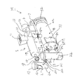
- an oiling apparatus M for oiling plastic is provided with an extruder 1 that gels discarded plastic pieces by frictional heat.
- the extruder 1 may be a normal extruder equipped with a lead screw therein.
- the extruder 1 includes a first buffer tank 2 provided with a step for automatically holding and transferring the gel-like plastic, and a second buffer tank disposed downstream of the first buffer tank 2.
- a buffer tank 3 is connected.
- the molten plastic from the second buffer tank 3 flows in an evaporator 4 disposed in parallel with the extruder 1 for gasifying the molten plastic while thermally decomposing it.
- a condenser 6 connected via an evaporator pipe 5 is disposed above the evaporator 4, and the plastic gas cooled by the condenser 6 is liquefied and stored in an oil tank.
- the extruder 1 and the evaporating pot 4 are arranged in parallel, and the line connecting the first and second buffer tanks 2 and 3 and the line connecting the extruder 1 and the evaporating pot 4 are orthogonal to each other.
- the conversion apparatus M is arranged in a U shape as a whole and has a compact configuration.
- the extruder 1 includes a hopper 10, from which a waste plastic strip 11 is fed between a lead screw 13 rotated by a motor 12 and a cylindrical casing 14. It is gelled by the heater heat applied by the heater that does not, and is discharged from the discharge pipe 15.
- the first buffer tank 2 is composed of a cylindrical body 2a arranged vertically, and the peripheral wall of the cylindrical body 2a is heated by a planar heating element 16 (FIG. 1), and the gel plastic is heated to 390 to 405 ° C.
- An openable and closable maintenance port 17 is formed at the upper end of the cylindrical body 2a, and an inflow pipe 18 extends from the upper peripheral wall of the cylindrical body 2a to the extruder 1, and the discharge pipe 15 and the inflow pipe of the extruder 1 are extended. 18 are connected by a joint 19.
- An outflow pipe 20 extends from the peripheral wall near the lower end of the cylindrical body 2a to the second buffer tank 3 side in a direction perpendicular to the inflow pipe 18.
- the second buffer tank 3 includes a cylindrical body 3 a that is disposed at a lower position than the first buffer tank 2 and is vertically disposed.
- An inflow pipe 21 that extends from an upper peripheral wall of the cylindrical body 3 a is provided via a joint 22.
- the cylindrical body 3a is formed slightly longer than the cylindrical body 2a of the first buffer tank 2, and its peripheral wall is covered with a planar heating element 23, whereby the molten plastic inside is heated to 400 to 415 ° C. and the upper end thereof
- a maintenance opening 24 that can be freely opened and closed is formed.
- the gas outflow pipe 25 is connected via a joint 26 to a gas inflow pipe 27 extending from a position corresponding to the evaporation space S of the end wall 4a of the evaporation pot 4. That is, the plastic is gradually heated through the first buffer tank 2 and the second buffer tank 3, and the second buffer tank 3 supports the evaporation pot 4 by sending the evaporated plastic gas to the evaporation pot 4. Plays an important role.
- a plastic outflow pipe 28 for feeding molten plastic into the evaporating pot 4 extends, and this plastic outflow pipe 28 is connected to the lower part of the end wall 4a of the evaporating pot 4 through a joint 29. Is connected to a plastic inflow pipe 30 extending from.
- the evaporating pot 4 comprises a horizontal cylinder 4a, the periphery of the cylinder 4a is covered with a planar heating element 31 such as a ceramic heater, and a maintenance port 32 can be opened and closed on the right end surface.
- a guide tube 5 a of the evaporation tube 5 extends upward, and this guide tube 5 a is connected to the evaporation tube 5 via a joint 33.
- a liquid level gauge 34 for detecting the liquid level L / S of the molten plastic in the cylindrical body 4a is provided at an appropriate position of the cylindrical body 34 (FIG. 2).
- a liquid level gauge 35 for that purpose is provided at a low position to control the liquid level.
- thermometers t 1 and t 2 are provided on the inner wall of the first and second buffer tanks 2 and 3 below the height at which the molten plastic of the cylindrical bodies 2a and 3a is stored, and the bottom wall of the evaporating pot 4 is appropriately disposed.
- Two thermometers t 3 and t 4 are installed at the positions.
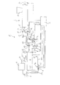
- the liquid level gauges 34 and 35, the thermometers t 1 , t 2 , t 3 and t 4 , the sheet heating elements 16, 23 and 31 and the motor 12 of the extruder 1 are connected to a controller C. (FIG. 2).
- PE polyethylene
- PP polypropylene
- Uniform heating and temperature control are important in the process of thermal decomposition of molten plastic.
- the first and second buffer tanks 2 and 3 and the evaporating pot 4 of the present apparatus do not use a stirrer.
- For uniform heating use a planar heating element to uniformly distribute from the surroundings.
- the amount of plastic to be heated is limited due to the relationship between heating and heat conduction.
- the heating temperature is 430 to 440 ° C. or higher, the molten plastic in contact with the buffer tank and the inner wall of the evaporation kettle 4 is carbonized. Accurate temperature control is important because it may adhere to the inner wall and heat conduction deteriorates, sometimes blowing up and causing accidents.
- the liquid surface (LS) position of the evaporating pot 4 is preferably the center position (height position) of the diameter of the cylindrical body 4a in the straight direction where the evaporation area is maximum, and the relationship between the liquid surface temperature and gasification is It is as shown below.
- the percentage (%) mentioned here indicates the rate of gasification in a certain time (for example, 1 hour), and indicates the rate of rate when the gasification rate at 423 ° C. is 100%. .
- the temperature of the molten plastic adjacent to the inner wall of the cylindrical body 4a is set at 415 to 430 ° C.
- the planar heater 31 provided on the outer peripheral surface of the cylindrical body 4a is set at 420 to 435 ° C.
- the heating of the evaporating pot 4 is performed by heating the outer peripheral surface, and thus the ambient heating is preferable because the structure is simpler than installing a heater inside, and maintenance inside the evaporating pot is easy.
- the size of the diameter of the cylindrical body 4a is limited, and the heating efficiency is preferably 35 to 45 cm, particularly around 40 cm.
- the 380 ° C. gel-like plastic of the extruder 1 passes through the discharge pipe 15 and the inflow pipe 18 and falls into the first buffer tank 2, and the liquid level rises from the bottom of the outflow pipe 20 at a predetermined height position. Then, the rise amount falls into the second buffer tank 3 through the outflow pipe 20 and the inflow pipe 21 at the top of the second buffer tank 3, and the liquid level thereof is the liquid level L ⁇ S of the evaporating pot 4.
- the molten plastic flows through the outflow pipe 28 and the inflow pipe 30 so as to be at the same height position.
- a part of the second buffer tank 3 is vaporized, and the vaporized gas flows into the evaporation space S in the evaporation pot 4 through the gas outlet pipe 25 and the gas inlet pipe 27 provided in the upper part of the tank. .
- the controller C controls the amount of extrusion of the extruder 1 and the rotation of the motor 12 so that the liquid level L ⁇ S in the evaporating pot 4 is at the center height position of the cylindrical body. Adjusted by control with watt density.
- Each of the buffer tanks 2 and 3 and the evaporating kettle does not require a stirrer, and is not provided with a valve for adjusting the flow rate of the plastic.
- the height position of the liquid level L / S of the evaporating pot 4 is controlled by the heating temperature, the diameter and length thereof.
- the voltage V is automatically adjusted by a thyristor, and the evaporation rate is increased by increasing the watt density of the heater. It is controlled to reduce the watt density to slow down the evaporation rate and return the liquid level to a predetermined position in a short time.
- the watt density of the planar heater 31 for controlling the liquid level of the plastic to 400 ° C. to 410 ° C. is 0.6 w / cm 2 to 1.4 w / cm 2 , and the diameter of the evaporation furnace 4 is 40 to 50 cm. Within the above range, the above range can be used for control.
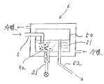
- the evaporation pipe 5 may be introduced into a predetermined amount of hydrocarbon oil 51 such as light oil, kerosene, or collected mixed oil. That is, since terephthalic acid generated by decomposition during the PET process is condensed in the hydrocarbon oil 51, if the collected oil is collected from the overflow pipe 52, the residue Pa of terephthalic acid is stored at the bottom of the main body 50. The residue may be removed from 53.
- the main body 50 is cooled by a coolant such as cooling water.
- FIG. 4 shows a capacitor 60 for neutralizing and removing chlorine (Cl) generated during the vinyl chloride treatment.
- a neutralizing agent 62 is accommodated in the main body 61 which is cooled by the refrigerant, and examples of the neutralizing agent include sodium hydroxide water (NaOH) or potassium hydroxide water (KOH).
- NaOH sodium hydroxide water
- KOH potassium hydroxide water
- the mixed oil collected on the liquid surface of these neutralizing agents is located, and when the mixed oil exceeds a certain amount, it is discharged to the outside through the overflow pipe 63.
- an evaporating pipe 5a extending from the evaporating kiln is extended, and a gas of collected oil is supplied. Chlorine in the gas becomes hydrochloric acid (HCl) in the neutralizer and is neutralized. If the evaporation pipe 5a is inclined downward, it is effectively prevented that water droplets stay in the evaporation pipe 5a.
- a drain port 64 is formed in the lower part of the main body
- a capacitor 70 for processing waste plastic containing both PE and vinyl chloride has a main body 71, and the neutralizing agent 73 is stored in the lower part of the main body 71, and the hydrocarbon oil 72 is stored on the neutralizer 73. Pa is condensed and removed, and chlorine (Cl) in the vinyl chloride settles and is neutralized by the neutralizing agent.
- the collected mixed oil overflows from the upper end of the overflow pipe 74 and is taken out to the outside.
- the lower end of the evaporation pipe 5a is opened to the hydrocarbon oil, and a drain port 75 is formed at the lower end of the main body. .
- the optimum dimensions for oiling 10 kg of polyethylene per hour are as follows.
- Extruder cylinder 1000L ⁇ 250 ⁇ 2.
- First buffer tank 150A (outer diameter 165.2mm, thickness 5mm) x 300L 4).
- Second buffer tank 150A ⁇ 400L 6).
- this apparatus is not particularly provided with a residue tank for storing residues, after operating the apparatus for a certain period of time, the maintenance ports 17, 24 and 32 attached to the respective parts are opened to remove the residues. .
- waste plastics it is possible to efficiently collect the mixed oil mainly composed of hydrocarbon oil corresponding to A heavy oil from PP and PE, and it is widely applied in the field of waste plastic use.
Landscapes
- Chemical & Material Sciences (AREA)
- Engineering & Computer Science (AREA)
- Oil, Petroleum & Natural Gas (AREA)
- Life Sciences & Earth Sciences (AREA)
- Wood Science & Technology (AREA)
- Chemical Kinetics & Catalysis (AREA)
- General Chemical & Material Sciences (AREA)
- Organic Chemistry (AREA)
- Production Of Liquid Hydrocarbon Mixture For Refining Petroleum (AREA)
- Separation, Recovery Or Treatment Of Waste Materials Containing Plastics (AREA)
Abstract
Priority Applications (3)
| Application Number | Priority Date | Filing Date | Title |
|---|---|---|---|
| US14/352,838 US20140246301A1 (en) | 2011-10-19 | 2012-10-19 | Liquefying apparatus |
| JP2013539704A JP6184868B2 (ja) | 2011-10-19 | 2012-10-19 | 油化装置 |
| EP12841744.1A EP2770039A4 (fr) | 2011-10-19 | 2012-10-19 | Appareil pétrochimique |
Applications Claiming Priority (4)
| Application Number | Priority Date | Filing Date | Title |
|---|---|---|---|
| JP2011-229409 | 2011-10-19 | ||
| JP2011229409 | 2011-10-19 | ||
| JP2012193314 | 2012-09-03 | ||
| JP2012-193314 | 2012-09-03 |
Publications (1)
| Publication Number | Publication Date |
|---|---|
| WO2013058366A1 true WO2013058366A1 (fr) | 2013-04-25 |
Family
ID=48141009
Family Applications (1)
| Application Number | Title | Priority Date | Filing Date |
|---|---|---|---|
| PCT/JP2012/077118 Ceased WO2013058366A1 (fr) | 2011-10-19 | 2012-10-19 | Appareil pétrochimique |
Country Status (4)
| Country | Link |
|---|---|
| US (1) | US20140246301A1 (fr) |
| EP (1) | EP2770039A4 (fr) |
| JP (1) | JP6184868B2 (fr) |
| WO (1) | WO2013058366A1 (fr) |
Cited By (2)
| Publication number | Priority date | Publication date | Assignee | Title |
|---|---|---|---|---|
| WO2019224985A1 (fr) * | 2018-05-24 | 2019-11-28 | 吉村慎一 | Dispositif de liquéfaction/réduction de déchets plastiques |
| CN119773204A (zh) * | 2024-12-31 | 2025-04-08 | 天津奥博特塑胶电子有限公司 | 一种电线电缆塑料挤出机 |
Families Citing this family (1)
| Publication number | Priority date | Publication date | Assignee | Title |
|---|---|---|---|---|
| WO2022011484A1 (fr) | 2020-07-15 | 2022-01-20 | Ecofuels Spa | Procédé pour produire un combustible liquide à partie de résidus plastiques ou polymères |
Citations (8)
| Publication number | Priority date | Publication date | Assignee | Title |
|---|---|---|---|---|
| JPS53118402A (en) * | 1977-03-25 | 1978-10-16 | Fujikura Ltd | Dry distillation and oil formation device of waste plastics |
| JPS5856556A (ja) * | 1981-09-29 | 1983-04-04 | Fujitsu Ltd | ト−ン検出方式 |
| JPH0465485A (ja) * | 1990-07-05 | 1992-03-02 | Nirai Kk | プラスチック油化再生装置 |
| JP2003034794A (ja) * | 2001-07-25 | 2003-02-07 | Japan Science & Technology Corp | 油中の塩素及び窒素の同時除去方法 |
| JP2005126454A (ja) * | 2003-10-21 | 2005-05-19 | Blest:Kk | プラスチック処理装置 |
| JP2005164094A (ja) * | 2003-12-01 | 2005-06-23 | Takuma Co Ltd | キルン式外熱炉 |
| JP2006152175A (ja) | 2004-11-30 | 2006-06-15 | Matsuda Kensetsu Kk | 油化装置 |
| JP2010284565A (ja) * | 2009-06-09 | 2010-12-24 | Blest:Kk | 有害ガス処理装置及び油化装置 |
Family Cites Families (18)
| Publication number | Priority date | Publication date | Assignee | Title |
|---|---|---|---|---|
| US3984288A (en) * | 1974-10-04 | 1976-10-05 | Sumitomo Electric Industries, Ltd. | Method for treatment of rubber and plastic wastes |
| US4208252A (en) * | 1974-10-04 | 1980-06-17 | Sumitomo Chemical Industries, Ltd. | Apparatus for treatment of rubber and plastic wastes |
| US5608136A (en) * | 1991-12-20 | 1997-03-04 | Kabushiki Kaisha Toshiba | Method and apparatus for pyrolytically decomposing waste plastic |
| JPH115984A (ja) * | 1997-06-17 | 1999-01-12 | Aasu Recycle Kk | 廃プラスチック溶融,脱塩化水素法 |
| JP2000273465A (ja) * | 1999-03-29 | 2000-10-03 | Hitachi Ltd | 廃プラスチック油化装置 |
| US20030050519A1 (en) * | 2001-09-11 | 2003-03-13 | Ming-Chin Cheng | Method for decomposing plastic waste to produce fuel materials and equipment for the method |
| JP2003190925A (ja) * | 2001-12-27 | 2003-07-08 | Fuji Electric Co Ltd | 有機化合物分解処理設備 |
| KR20040048368A (ko) * | 2002-01-25 | 2004-06-09 | 요우이치 와다 | 플라스틱의 유화방법 및 유화플랜트 |
| JP2003213276A (ja) * | 2002-01-25 | 2003-07-30 | Yoichi Wada | プラスチックの油化方法及び油化プラント |
| AU2005221728B2 (en) * | 2004-03-14 | 2010-10-28 | Future Energy Investments Pty Ltd | Process and plant for conversion of waste material to liquid fuel |
| JP2006316196A (ja) * | 2005-05-13 | 2006-11-24 | Yasuo Ishikawa | 油化装置 |
| EP2042581A4 (fr) * | 2006-05-25 | 2012-05-16 | Blest Co Ltd | Appareil de liquéfaction |
| US8193403B2 (en) * | 2006-08-24 | 2012-06-05 | Agilyx Corporation | Systems and methods for recycling plastic |
| US7758729B1 (en) * | 2006-08-24 | 2010-07-20 | Plas2Fuel Corporation | System for recycling plastics |
| TWI404748B (zh) * | 2009-11-10 | 2013-08-11 | Enrestec Inc | 連續式裂解系統及其應用 |
| KR100955297B1 (ko) * | 2009-11-23 | 2010-04-30 | 주식회사 에코크레이션 | 폐플라스틱의 오일 환원 장치 |
| EP2516592B1 (fr) * | 2009-12-22 | 2018-06-13 | Cynar Plastics Recycling Limited | Conversion de déchets plastiques en carburant |
| JP5639249B2 (ja) * | 2013-11-14 | 2014-12-10 | キヤノン電子株式会社 | 振動素子、光走査装置及び映像投影装置並びに画像形成装置 |
-
2012
- 2012-10-19 WO PCT/JP2012/077118 patent/WO2013058366A1/fr not_active Ceased
- 2012-10-19 JP JP2013539704A patent/JP6184868B2/ja not_active Expired - Fee Related
- 2012-10-19 EP EP12841744.1A patent/EP2770039A4/fr not_active Withdrawn
- 2012-10-19 US US14/352,838 patent/US20140246301A1/en not_active Abandoned
Patent Citations (8)
| Publication number | Priority date | Publication date | Assignee | Title |
|---|---|---|---|---|
| JPS53118402A (en) * | 1977-03-25 | 1978-10-16 | Fujikura Ltd | Dry distillation and oil formation device of waste plastics |
| JPS5856556A (ja) * | 1981-09-29 | 1983-04-04 | Fujitsu Ltd | ト−ン検出方式 |
| JPH0465485A (ja) * | 1990-07-05 | 1992-03-02 | Nirai Kk | プラスチック油化再生装置 |
| JP2003034794A (ja) * | 2001-07-25 | 2003-02-07 | Japan Science & Technology Corp | 油中の塩素及び窒素の同時除去方法 |
| JP2005126454A (ja) * | 2003-10-21 | 2005-05-19 | Blest:Kk | プラスチック処理装置 |
| JP2005164094A (ja) * | 2003-12-01 | 2005-06-23 | Takuma Co Ltd | キルン式外熱炉 |
| JP2006152175A (ja) | 2004-11-30 | 2006-06-15 | Matsuda Kensetsu Kk | 油化装置 |
| JP2010284565A (ja) * | 2009-06-09 | 2010-12-24 | Blest:Kk | 有害ガス処理装置及び油化装置 |
Non-Patent Citations (1)
| Title |
|---|
| See also references of EP2770039A4 |
Cited By (2)
| Publication number | Priority date | Publication date | Assignee | Title |
|---|---|---|---|---|
| WO2019224985A1 (fr) * | 2018-05-24 | 2019-11-28 | 吉村慎一 | Dispositif de liquéfaction/réduction de déchets plastiques |
| CN119773204A (zh) * | 2024-12-31 | 2025-04-08 | 天津奥博特塑胶电子有限公司 | 一种电线电缆塑料挤出机 |
Also Published As
| Publication number | Publication date |
|---|---|
| JP6184868B2 (ja) | 2017-08-23 |
| EP2770039A1 (fr) | 2014-08-27 |
| US20140246301A1 (en) | 2014-09-04 |
| EP2770039A4 (fr) | 2015-06-24 |
| JPWO2013058366A1 (ja) | 2015-04-02 |
Similar Documents
| Publication | Publication Date | Title |
|---|---|---|
| US6126907A (en) | Thermal decomposition apparatus of reversed temperature gradient type for polymer waste | |
| JP6924305B2 (ja) | 炉 | |
| JP5368790B2 (ja) | 油化装置 | |
| US7473348B2 (en) | Diesel oil from residues by catalytic depolymerization with energy input from a pump-agitator system | |
| CN102260515A (zh) | 废弃塑料热裂解处理方法和装置 | |
| US20140171701A1 (en) | Apparatus for conducting thermolysis of plastic waste and method of thermolysis in continuous manner | |
| JP6184868B2 (ja) | 油化装置 | |
| EP1707614A1 (fr) | Procédé de craquage thermique ou catalytique de charges hydrocarbures et système correspondant | |
| EP2393875B1 (fr) | Procédé de dépolymérisation thermocatalytique de déchets de matière plastique, système pour la dépolymérisation thermocatalytique de déchets de matière plastique et réacteur pour la dépolymérisation thermocatalytique de déchets de matière plastique | |
| JP5850378B2 (ja) | 油化装置 | |
| US5947721A (en) | Recycling apparatus for obtaining oil from plastic waste | |
| CN103450913B (zh) | 一种垃圾热裂解机 | |
| KR20140061045A (ko) | 수지 유화 추출장치 | |
| JP5906498B2 (ja) | 油化装置 | |
| CN217868729U (zh) | 一种废矿物油低温精制装置 | |
| JP6704745B2 (ja) | ポリブテン樹脂の廃棄処分方法、廃棄処分装置及び生成油 | |
| CN213667958U (zh) | 一种用于催化裂化汽油碱渣处理的硫酸钠回收装置 | |
| CN104673350B (zh) | 可移动的倾斜式炼油装置 | |
| EP1108774B1 (fr) | Dispositif du type à gradient de température inversée pour la décomposition thermique de déchets de polymères | |
| CN209810136U (zh) | 一种饲料添加剂反应釜抗凝结装置 | |
| CN2748457Y (zh) | 卧式废塑料油化主体反应装置 | |
| WO2016147344A1 (fr) | Dispositif de conversion continue du plastique en pétrole | |
| JP3938962B2 (ja) | 廃プラスチックの油化還元装置 | |
| CN202448325U (zh) | 一种反应挤出的配套设备 | |
| JPWO2016147343A1 (ja) | プラスチックの連続式油化装置 |
Legal Events
| Date | Code | Title | Description |
|---|---|---|---|
| 121 | Ep: the epo has been informed by wipo that ep was designated in this application |
Ref document number: 12841744 Country of ref document: EP Kind code of ref document: A1 |
|
| ENP | Entry into the national phase |
Ref document number: 2013539704 Country of ref document: JP Kind code of ref document: A |
|
| REEP | Request for entry into the european phase |
Ref document number: 2012841744 Country of ref document: EP |
|
| WWE | Wipo information: entry into national phase |
Ref document number: 2012841744 Country of ref document: EP |
|
| WWE | Wipo information: entry into national phase |
Ref document number: 14352838 Country of ref document: US |
|
| NENP | Non-entry into the national phase |
Ref country code: DE |