WO2013061914A1 - 電極材料、電極材料の製造方法、電極および二次電池 - Google Patents
電極材料、電極材料の製造方法、電極および二次電池 Download PDFInfo
- Publication number
- WO2013061914A1 WO2013061914A1 PCT/JP2012/077217 JP2012077217W WO2013061914A1 WO 2013061914 A1 WO2013061914 A1 WO 2013061914A1 JP 2012077217 W JP2012077217 W JP 2012077217W WO 2013061914 A1 WO2013061914 A1 WO 2013061914A1
- Authority
- WO
- WIPO (PCT)
- Prior art keywords
- electrode
- conductive material
- base material
- slurry
- conductive
- Prior art date
- Legal status (The legal status is an assumption and is not a legal conclusion. Google has not performed a legal analysis and makes no representation as to the accuracy of the status listed.)
- Ceased
Links
Images


Classifications
-
- H—ELECTRICITY
- H01—ELECTRIC ELEMENTS
- H01M—PROCESSES OR MEANS, e.g. BATTERIES, FOR THE DIRECT CONVERSION OF CHEMICAL ENERGY INTO ELECTRICAL ENERGY
- H01M4/00—Electrodes
- H01M4/02—Electrodes composed of, or comprising, active material
- H01M4/64—Carriers or collectors
- H01M4/66—Selection of materials
- H01M4/661—Metal or alloys, e.g. alloy coatings
-
- H—ELECTRICITY
- H01—ELECTRIC ELEMENTS
- H01M—PROCESSES OR MEANS, e.g. BATTERIES, FOR THE DIRECT CONVERSION OF CHEMICAL ENERGY INTO ELECTRICAL ENERGY
- H01M4/00—Electrodes
- H01M4/02—Electrodes composed of, or comprising, active material
- H01M4/64—Carriers or collectors
- H01M4/66—Selection of materials
- H01M4/663—Selection of materials containing carbon or carbonaceous materials as conductive part, e.g. graphite, carbon fibres
-
- H—ELECTRICITY
- H01—ELECTRIC ELEMENTS
- H01M—PROCESSES OR MEANS, e.g. BATTERIES, FOR THE DIRECT CONVERSION OF CHEMICAL ENERGY INTO ELECTRICAL ENERGY
- H01M4/00—Electrodes
- H01M4/02—Electrodes composed of, or comprising, active material
- H01M4/64—Carriers or collectors
- H01M4/66—Selection of materials
- H01M4/665—Composites
- H01M4/667—Composites in the form of layers, e.g. coatings
-
- H—ELECTRICITY
- H01—ELECTRIC ELEMENTS
- H01M—PROCESSES OR MEANS, e.g. BATTERIES, FOR THE DIRECT CONVERSION OF CHEMICAL ENERGY INTO ELECTRICAL ENERGY
- H01M4/00—Electrodes
- H01M4/02—Electrodes composed of, or comprising, active material
- H01M4/64—Carriers or collectors
- H01M4/66—Selection of materials
- H01M4/668—Composites of electroconductive material and synthetic resins
-
- H—ELECTRICITY
- H01—ELECTRIC ELEMENTS
- H01M—PROCESSES OR MEANS, e.g. BATTERIES, FOR THE DIRECT CONVERSION OF CHEMICAL ENERGY INTO ELECTRICAL ENERGY
- H01M10/00—Secondary cells; Manufacture thereof
- H01M10/05—Accumulators with non-aqueous electrolyte
- H01M10/052—Li-accumulators
- H01M10/0525—Rocking-chair batteries, i.e. batteries with lithium insertion or intercalation in both electrodes; Lithium-ion batteries
-
- H—ELECTRICITY
- H01—ELECTRIC ELEMENTS
- H01M—PROCESSES OR MEANS, e.g. BATTERIES, FOR THE DIRECT CONVERSION OF CHEMICAL ENERGY INTO ELECTRICAL ENERGY
- H01M4/00—Electrodes
- H01M4/02—Electrodes composed of, or comprising, active material
- H01M4/13—Electrodes for accumulators with non-aqueous electrolyte, e.g. for lithium-accumulators; Processes of manufacture thereof
-
- H—ELECTRICITY
- H01—ELECTRIC ELEMENTS
- H01M—PROCESSES OR MEANS, e.g. BATTERIES, FOR THE DIRECT CONVERSION OF CHEMICAL ENERGY INTO ELECTRICAL ENERGY
- H01M4/00—Electrodes
- H01M4/02—Electrodes composed of, or comprising, active material
- H01M4/13—Electrodes for accumulators with non-aqueous electrolyte, e.g. for lithium-accumulators; Processes of manufacture thereof
- H01M4/139—Processes of manufacture
-
- Y—GENERAL TAGGING OF NEW TECHNOLOGICAL DEVELOPMENTS; GENERAL TAGGING OF CROSS-SECTIONAL TECHNOLOGIES SPANNING OVER SEVERAL SECTIONS OF THE IPC; TECHNICAL SUBJECTS COVERED BY FORMER USPC CROSS-REFERENCE ART COLLECTIONS [XRACs] AND DIGESTS
- Y02—TECHNOLOGIES OR APPLICATIONS FOR MITIGATION OR ADAPTATION AGAINST CLIMATE CHANGE
- Y02E—REDUCTION OF GREENHOUSE GAS [GHG] EMISSIONS, RELATED TO ENERGY GENERATION, TRANSMISSION OR DISTRIBUTION
- Y02E60/00—Enabling technologies; Technologies with a potential or indirect contribution to GHG emissions mitigation
- Y02E60/10—Energy storage using batteries
-
- Y—GENERAL TAGGING OF NEW TECHNOLOGICAL DEVELOPMENTS; GENERAL TAGGING OF CROSS-SECTIONAL TECHNOLOGIES SPANNING OVER SEVERAL SECTIONS OF THE IPC; TECHNICAL SUBJECTS COVERED BY FORMER USPC CROSS-REFERENCE ART COLLECTIONS [XRACs] AND DIGESTS
- Y02—TECHNOLOGIES OR APPLICATIONS FOR MITIGATION OR ADAPTATION AGAINST CLIMATE CHANGE
- Y02P—CLIMATE CHANGE MITIGATION TECHNOLOGIES IN THE PRODUCTION OR PROCESSING OF GOODS
- Y02P70/00—Climate change mitigation technologies in the production process for final industrial or consumer products
- Y02P70/50—Manufacturing or production processes characterised by the final manufactured product
Definitions
- the present invention relates to an electrode material used for an electrode of a secondary battery, a manufacturing method thereof, an electrode using the electrode material, and a secondary battery using the electrode.
- Patent Document 1 and Patent Document 2 describe a current collector in which a film made of carbon fine particles as a conductive material and a film-forming compound is formed on the surface of a base material such as an aluminum foil or a copper foil.
- Patent Document 3 describes a current collector in which a conductive layer made of carbon powder (conductive material) and a binder is provided between an active material.
- Patent Document 4 describes a current collector in which a conductive coating layer using carbon as a conductive agent (conductive substance) is provided on the surface.
- FIG. 6 is a schematic cross-sectional view for explaining the configuration of the current collector in the prior art.
- the conductive material layer 3b is uniformly formed on the surface of the base material 3a made of metal foil. That is, the entire surface of the base material 3a is covered with the conductive material layer 3b.
- the applicant of the present application has invented an electrode material (current collector) configured such that the conductive material is arranged in an island shape on the surface of the base material. Thereby, both reduction of contact resistance and weldability can be achieved.
- an island structure As appropriate
- an active material layer is further coated and pressure-bonded on the island-like structure of the conductive material.
- adhesion between the active material layer and the substrate is ensured.
- the handling of the current collector and the active material are not performed between the formation process of the island-like structure of the conductive material and the coating process of the active material layer.
- the island-like structure of the conductive material is easily peeled by contact with the surface of the current collector by a roller or the like disposed on the layer coating machine. Then, it can be considered that the effect of lowering the contact resistance is reduced by peeling off the island-like structure of the conductive material.
- the present invention has been devised in view of the above-described problems, is excellent in tab weldability, realizes a reduction in contact resistance with the active material layer, and is used for a base material of a conductive material arranged in an island shape. It is an object of the present invention to provide an electrode material with good adhesion and a method for manufacturing the same, an electrode using the electrode material, and a secondary battery that achieves low internal resistance using the electrode.
- an electrode material according to the present invention is an electrode material including a base material including a metal foil and a conductive substance provided on at least one surface of the base material, and has a 300 ⁇ m square.
- the conductive material is arranged in an island shape on the surface of the substrate, and the conductive material is fixed to the surface of the substrate together with the hydrophobic resin and the water-soluble resin.
- the surface of the base material including the metal foil made of a conductive material such as carbon has a portion not covered with the conductive material.
- the portion not covered with the conductive material becomes 20% or more. Therefore, for example, when this electrode material is used as a current collector of an electrode of a lithium ion secondary battery, it is easy to weld a metal tab for connecting the current collector to the battery terminal. It becomes.
- the electrode material when used as, for example, a current collector of an electrode of a lithium ion secondary battery by providing a conductive material on the surface of the base material, preferably so that the coverage is 1% or more, The contact resistance between the electric current and the active material layer laminated on the current collector is reduced.
- the adhesion between the conductive material and the base material is improved by the hydrophobic resin, and the coating property of the slurry containing the conductive material in the manufacturing process is improved by the water-soluble resin in the manufacturing process.
- the island-like structure is arranged in the island-like structure with good adhesion to the base material that is a metal foil as a mixture of the conductive material and these resins.
- the total adhesion amount of the conductive substance, water-soluble resin and hydrophobic resin adhering to the surface of the substrate is in the range of 0.01 to 0.50 g / m 2.
- the conductive material may be provided on one side of the base material, or may be provided on both sides of the base material, but the above-described range of the adhesion amount indicates a preferable range on each surface provided with the conductive material.
- the conductive material is arranged in the form of islands on the surface of the base material by setting the amount of adhesion to the above-described range, and the base material is moderately formed by setting the amount of adhesion to 0.50 g / m 2 or less. Since the coverage is exposed, metal tabs and the like are welded well. Further, when the electrode material is used as, for example, a current collector of an electrode of a lithium ion secondary battery by setting the adhesion amount to 0.01 g / m 2 or more, the current collector is laminated on the current collector. The contact resistance with the active material layer is reduced.
- the method for producing an electrode material according to the present invention includes a coating step of applying a slurry containing a conductive substance, a water-soluble resin, and an aqueous emulsion solution of a hydrophobic resin to a surface of a substrate, and drying for drying the slurry.
- the conductive materials are aggregated in the solution before or after the slurry is applied to the surface of the substrate.
- the hydrophobic resin is uniformly dispersed in the slurry.
- the water-soluble resin is mixed with the slurry, the wettability of the slurry containing the water-soluble resin is improved in the coating process, and the slurry is applied well without being splashed on the surface of the substrate to form a polka dot.
- the conductive material is aggregated before or after coating, so that the conductive material in the slurry applied to the surface of the base material is the surface of the substrate. It is arranged in an island shape. Then, by drying the slurry in the drying step, the conductive material is fixed to the surface of the substrate together with the hydrophobic resin and the water-soluble resin.
- a slurry having a carbon content of 0.1 to 7% by mass as a conductive substance is applied to the surface of the substrate in the application step.
- the conductive material is suitably aggregated in the slurry before or after being applied to the base material, and the conductive material is arranged in an island shape on the surface of the base material.
- the content of the water-soluble resin in the slurry is 0.25% by mass or more, and the content of the hydrophobic resin is 0.01% by mass or more. And it is preferable that the sum total of content of water-soluble resin and content of hydrophobic resin in a slurry shall be 11 mass% or less.
- the wettability of the slurry with respect to the base material is suitably improved by the water-soluble resin within this content range, and the slurry is satisfactorily applied to the base material.
- the island-shaped structure is fixed to the base material with good adhesion by the hydrophobic resin in the content range.
- the reduction effect of contact resistance can be acquired by making content of all the resin into 11 mass% or less.
- the electrode for a secondary battery according to the present invention is an electrode for a secondary battery using the electrode material described above, and is configured by providing an active material layer on the surface of the electrode material provided with a conductive material.
- the contact resistance between the electrode material that is the current collector and the active material layer is reduced by the conductive material arranged in an island shape on the surface of the base material.
- the secondary battery according to the present invention is a secondary battery having a positive electrode and a negative electrode, and at least one of the positive electrode and the negative electrode is configured using the electrode according to the present invention.
- the secondary battery since the contact resistance between the electrode material that is the current collector and the active material layer is reduced, the secondary battery has an internal resistance that is low as the secondary battery. It becomes.
- the conductive material is arranged in an island shape on the surface of the metal foil as the base material, and the amount of the conductive material attached is limited.
- the contact resistance with the active material layer can be reduced.
- this island-like structure is closely attached to the metal foil that is the base material, and the island-like structure is formed in the manufacturing process before handling the electrode material or before coating the active material layer Therefore, the effect of reducing the contact resistance by the island structure is not impaired.
- an island-like structure of a conductive material can be formed with good adhesion on the surface of a base material, so that weldability such as a tab is good, and contact resistance with an active material layer Can be manufactured with stable quality. Further, since an aqueous solution is used, it is possible to reduce the environmental load due to solvent vapor in the manufacturing process.
- an electrode material on which a suitable island-like structure is formed can be produced.
- an electrode material with good quality can be manufactured.
- the contact resistance between the electrode material and the active material layer can be reduced.
- internal resistance can be reduced.
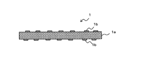
- a current collector (electrode material) 1 according to the present embodiment includes a base material 1a made of a metal foil and a conductive material 1b arranged in an island shape on the surface of the base material 1a.
- the conductive material 1b is disposed on both surfaces of the base material 1a.
- island shape refers to a state in which the conductive material 1b is arranged such that at least a part of the surface of the substrate 1a is exposed without being covered with the conductive material 1a.
- the aggregates of a plurality of conductive materials 1b may be arranged isolated from each other, or the aggregates may be joined and arranged in a mesh shape.
- the current collector 1 according to this embodiment can be suitably used as, for example, a current collector of an electrode of a lithium ion secondary battery.
- the electrode using the current collector 1 will be described later.
- the current collector 1 When the current collector 1 is observed in a 300 ⁇ m square visual field (that is, a square visual field having an area of about 0.1 mm 2 ) in an arbitrary region where the conductive material 1 b on the surface of the base material 1 a is disposed,
- a structure in which the conductive material 1b is arranged in an island shape on the surface of 1a when the current collector 1 is used as an electrode of a battery, it is made of metal that electrically connects the current collector 1 and the battery terminal It is possible to improve tab weldability when welding a tab (not shown).
- the coverage of the surface of the substrate 1a with the conductive material 1b of the substrate 1a is 1 to 80 when observed in a 300 ⁇ m square field of view in an arbitrary region where the conductive material 1b is disposed on the surface of the substrate 1a. % Is preferred.
- the coverage by the conductive material 1b is 1% or more, the current collector 1 and the active material layer 2 (see FIG. 2) laminated on the surface of the current collector 1 when used as an electrode of a secondary battery The contact resistance between them can be further reduced.
- the coverage is more preferably 10 to 70%, and further preferably 30 to 60%.
- the conductive material 1b is evenly arranged on the surface of the substrate 1a at least in the unit of the observation area described above. Since the conductive material 1b is arranged in an island shape within a sufficiently small area, practically uniform contact resistance and tab weldability can be obtained.
- the coverage of the surface of the base material 1a with the conductive material 1b is obtained by, for example, photographing the surface of the prepared sample using an SEM (scanning electron microscope) and using the carbon contained in the photographed field of view.
- the surface coverage area can be calculated and obtained by image processing.
- the amount of adhesion per unit area of the surface of the base material 1a of the conductive material 1b is 0.01 to about the total amount of the conductive material 1b and a water-soluble resin and a hydrophobic resin (not shown) that are binders.
- a range of 0.50 g / m 2 is preferable.
- the coating weight, 0.03 g / m 2 or more preferably, 0.05 g / m 2 or more is more preferable.
- the adhesion amount is more preferably 0.40 g / m 2 or less, and further preferably 0.30 g / m 2 or less.
- the electrically conductive substance 1b is arrange
- the surface of the base material 1a is appropriately adjusted by setting the adhesion amount to preferably 0.50 g / m 2 or less, more preferably 0.40 g / m 2 or less, and still more preferably 0.30 g / m 2 or less. Since the exposed coverage is obtained, good tab weldability is obtained.
- the adhesion amount preferably 0.01 g / m 2 or more, more preferably 0.03 g / m 2 or more, more preferably by a 0.05 g / m 2 or more, the current collector 1, the secondary When used as a battery electrode, the contact resistance with the active material layer 2 (see FIG. 2) laminated on the surface of the current collector 1 can be reduced.
- the adhesion amount per unit area of the surface of the base material 1a of the conductive material 1b can be obtained as follows. First, the mass of a sample obtained by applying a solution containing the conductive material 1b, a water-soluble resin and a hydrophobic resin to the substrate 1a and drying it is measured. Next, the surface of the sample is wiped with water and alcohol, and the mass after removing the conductive material 1b, the water-soluble resin and the hydrophobic resin is measured. And the adhesion amount per unit area in the surface of the base material 1a of the electrically conductive substance 1b is computable by dividing the mass difference by the area of a sample.
- the base material 1a can use metals, such as aluminum (Al) and copper (Cu), which are generally used as electrode materials for secondary batteries.
- the substrate 1a is generally used in the form of a foil having a thickness of about 5 to 50 ⁇ m.
- the plate-shaped or thick foil-shaped substrate 1a is coated with a solution containing the conductive material 1b and dried, and then rolled. You may make it thin by giving.
- the base material 1a is not limited to Al, Cu, etc. of a specific composition, When using for an electrode, the various pure metals suitable for the use environment of the electrode, or its alloy can be used.
- the conductive material 1b is arranged in an island shape so as to cover 1 to 80% of the surface of the substrate 1a when observed in a 300 ⁇ m square field of view, and the current collector 1 and the active material layer that are configured together with the substrate 1a (Refer to FIG. 2).
- a carbon-based conductive material carbon
- Various carbon blacks such as natural or artificial crystalline graphite, expanded graphite, artificial graphite, pyrolytic graphite, or acetylene black can be used as the carbon-based conductive material.
- the island-like structure made of the conductive material 1b has good adhesion to the surface of the substrate 1a by a binder (not shown) described later.
- the binder (not shown) includes a hydrophobic resin for improving the adhesion between the island-like structure made of the conductive material 1b and the surface of the substrate 1a, and a solution containing the hydrophobic resin and the conductive material 1b. It is comprised from the water-soluble resin for improving the applicability
- the hydrophobic resin needs to be mixed with a water-soluble resin, it is preferably a resin that can form an aqueous emulsion.
- a hydrophobic resin for example, one or a mixture of two or more of polyethylene resins, polypropylene resins, polyester resins, urethane resins, acrylic resins, and the like can be used.
- water-soluble resin for example, one or two or more kinds of carboxyvinyl polymer, carboxymethylcellulose and its salts (sodium salt, ammonium salt), polyvinyl alcohol, and the like can be mixed and used.
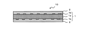
- Electrode Next, with reference to FIG. 2, the structure of the electrode of the lithium ion secondary battery using the current collector 1 according to this embodiment will be described.
- An electrode 10 shown in FIG. 2 includes a current collector 1 according to this embodiment and an active material layer 2 laminated on the surface (both sides) of the current collector 1.
- a metal such as Al or an Al alloy can be used as the base material of the current collector 1.
- the positive electrode active material a known material, for example, it can be used LiCoO 2, LiNiO 2, lithium-containing oxides such as LiMn 2 O 4.
- the method for producing the positive electrode active material layer 2 is not particularly limited, and a known method, for example, a powdery lithium-containing oxide is added with a conductive material, a solvent, etc., if necessary, in addition to a binder. Then, after sufficiently kneaded, it can be applied to the current collector 1, dried and pressed.
- the active material layer 2 may be laminated on one side provided with the conductive material 1b.
- the negative electrode of the lithium ion secondary battery when constituting the negative electrode of the lithium ion secondary battery, a metal such as Cu, Cu alloy, nickel (Ni), Ni alloy, stainless steel or the like can be used. Moreover, as a negative electrode active material, a graphite-type carbon material can be used, for example, and it can manufacture like the manufacturing method of the active material layer 2 of a positive electrode.
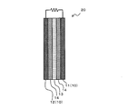
- a lithium ion secondary battery (secondary battery) 20 shown in FIG. 3 includes a positive electrode 11 and a negative electrode 12, which are electrodes 10 using the current collector 1 according to the present embodiment, a separator 13, and an electrolytic solution 14. It is comprised including. The positive electrode 11 and the negative electrode 12 are separated by a separator 13, and the electrolyte solution 14 is filled between the positive electrode 11 and the negative electrode 12 and the separator 13. Further, the entire lithium ion secondary battery 20 is housed in a container (not shown), and the positive electrode 11 and the negative electrode 12 are each welded with a metal tab (not shown) to be electrically connected to an electrode terminal (not shown). Connected.
- the active material layer 2 containing the above-mentioned positive electrode active material and negative electrode active material is formed on the surface of the current collector 1 according to this embodiment, respectively.
- the separator 13 and the electrolyte solution 14 can each be comprised using a well-known material.
- the separator 13 for example, a polyethylene microporous film having a thickness of 20 to 30 ⁇ m can be used.
- the electrolyte solution 14 for example, a non-aqueous electrolyte solution in which an electrolyte such as LiPF 6 or LiBF 4 is dissolved in an organic solvent such as propylene carbonate or ethylene carbonate can be used.
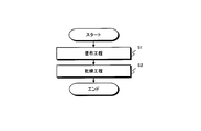
- the manufacturing method of the current collector 1 in the present embodiment includes the coating step S1 and the drying step S2 in this order.
- the current collector 1 applies a slurry containing a conductive material 1b, an aqueous emulsion of a hydrophobic resin, and a water-soluble resin to the surface of the substrate 1a made of a metal foil, and applies the slurry to the surface of the substrate 1a.
- the conductive material 1b can be produced by a production method including an application step S1 for aggregating the conductive material 1b in the slurry and a drying step S2 for drying the slurry.
- the conductive material 1b that is uniformly dispersed in the slurry aggregates over time. That is, the conductive material 1b aggregates before or after the prepared slurry is applied to the surface of the substrate 1a. And in the slurry apply
- the hydrophobic resin is filled in the gap between the base material 1a and the particles of the conductive material 1b in contact with the base material 1a, and the island-like structure of the conductive material 1b is firmly adhered to the surface of the base material 1a with good adhesion. Can be fixed. That is, this island-like structure is fixed to the surface of the substrate 1a as a mixture of the conductive material 1b, the hydrophobic resin, and the water-soluble resin described later.
- the coating process will be described in detail.
- the coating step S1 First, the coating step S1 will be described.
- it is effective to adjust the particle size and concentration of the conductive material 1b contained in the slurry, and the concentration of the hydrophobic resin and the water-soluble resin as binders. is there.
- the particle size and concentration of the conductive material 1b and the concentration of the binder are adjusted, the viscosity of the slurry changes, so that the coating property and the distribution of the conductive material 1b after drying change.
- carbon is used as the conductive material 1b, it is preferable to use carbon having an average particle size of 0.01 to 1 ⁇ m.
- carbon is contained in the slurry in an amount of 0.1 to 7% by mass.
- the average particle size is 0.01 ⁇ m or more and the concentration (content) to 7% by mass or less, the viscosity of the slurry does not increase excessively and the aggregation of carbon particles does not become too large. Can be obtained.
- the average particle diameter of carbon as the conductive material 1b is set to 1 ⁇ m or less and the concentration of carbon to 0.1% by mass or more, an island-like structure is formed, and the carbon and the base material as the conductive material 1b are formed.
- the contact point with the metal foil which is the material 1a is sufficient, and the effect of reducing the contact resistance between the current collector 1 and the active material layer 2 (see FIG. 2) can be obtained.
- the island-like structure of the conductive material 1b can be disposed on the substrate 1a that is a metal foil with good adhesion. For this reason, when manufacturing an electrode, it can prevent that the island-like structure of the electrically conductive material 1b peels until the application
- the concentration of the hydrophobic resin is preferably 0.01% by mass or more and about 11% by mass or less, more preferably 0.10% by mass or more, and 0.25% by mass or more. Is more preferable.
- hydrophobic resin and the water-soluble resin can be mixed by dispersing the hydrophobic resin in water as an aqueous emulsion.
- hydrophobic resin water-based emulsion resin
- polyethylene resins polypropylene resins
- polyester resins polypropylene resins
- urethane resins acrylic resins, and the like
- the slurry which is an aqueous emulsion solution of a hydrophobic resin in which the conductive material 1b is dispersed, is repelled in the above-described concentration range of the hydrophobic resin for water repellency on the surface of the substrate 1a, and is in a so-called water repellency state.
- concentration of the hydrophobic resin is increased to sufficiently increase the viscosity of the slurry beyond the above-described concentration range.
- the concentration of the hydrophobic resin is too high, the contact resistance (that is, the internal resistance of the secondary battery) increases, and the characteristics regarding the contact resistance cannot be satisfied.
- the wettability with respect to the base material 1a which is a metal foil is improved by mixing the water-soluble resin with the aqueous emulsion solution of the hydrophobic resin. Accordingly, the coating solution can be applied to the base material 1a without forming a polka dot shape, and the island-like structure of the conductive material 1b can be fixed to the base material 1a with good adhesion.
- the water-soluble resin for example, one or a mixture of two or more of carboxyvinyl polymer, carboxymethylcellulose and salts thereof (sodium salt, ammonium salt), polyvinyl alcohol, and the like can be used.
- concentration of water-soluble resin shall be 0.25 mass% or more and about 11 mass% or less.
- the total resin concentration of the hydrophobic resin and the water-soluble resin as a sufficient amount of resin necessary to satisfactorily adhere the island-like structure of the conductive material 1b to the surface of the substrate 1a is 0.5 to It is preferable to set it as 11 mass%. By setting it as 0.5 mass% or more, favorable coating property and adhesiveness can be obtained, and by setting it as 11 mass% or less, the effect of reducing favorable contact resistance (internal resistance of the secondary battery). Can be obtained.
- a carbon-based material can be used as the conductive substance 1b. Specifically, natural or artificial crystalline graphite, expanded graphite, artificial graphite, pyrolytic graphite and various carbon blacks can be used.
- the conductive material 1b is applied to both surfaces or one surface of the substrate 1a.
- the drying step S2 is a step for evaporating the solvent after the coating step S1.
- drying may be performed at room temperature, or heat drying using a heat treatment furnace or the like may be performed as necessary.
- the drying temperature should be 100 ° C. to 170 ° C. as the temperature at which the solvent of the water-based emulsion solution evaporates easily (reason for lower limit) and does not decrease the strength of the metal foil as the substrate 1a (reason for upper limit).
- the temperature is preferably 140 ° C. to 170 ° C. In particular, when the temperature is 140 ° C. or higher, the hydrophobic resin is softened by heat, and the adhesion between the substrate 1a and the hydrophobic resin is improved. As a result, the adhesion between the base material 1a and the conductive material 1b can be further improved.
- the drying time is not particularly limited, but when drying at 100 ° C. to 170 ° C., it is preferably 0.1 minutes to 5 minutes. By setting it as 0.1 minutes or more, a solvent can fully be evaporated, and the strength reduction of the metal foil which is the base material 1a can be prevented by setting it as 5 minutes or less.
- a sample was prepared by the following method.
- (Base material) As a base material, a 15 ⁇ m thick Al foil made of 1000 series Al alloy or a 20 ⁇ m thick Cu foil made of 99.99% pure copper was used. In Tables 1 to 3 to be described later, whether each sample used Al foil or Cu foil was indicated by “Al” or “Cu” in the column of base material.
- aqueous emulsion solution using polypropylene (PP) or polyethylene (PE) as a hydrophobic resin was prepared, and the prepared aqueous emulsion solution was diluted with pure water and used. Moreover, the sample which does not use hydrophobic resin was also produced for the comparison.
- Carboxymethylcellulose (CMC) sodium salt was used as the water-soluble resin. Moreover, the sample which does not use water-soluble resin was also produced for the comparison.
- Carbon black having an average particle size of 0.06 ⁇ m As the conductive material, carbon black having an average particle size of 0.06 ⁇ m (Toka Black # 4300 manufactured by Tokai Carbon Co., Ltd.) was used.
- Coating process In coating, pure water was used as a solvent, and for each sample, a solution prepared with the concentration of carbon black (conductive material), the type and concentration of hydrophobic resin, and the concentration of water-soluble resin shown in Tables 1 to 3 (The slurry was applied to the surface of the substrate using a bar coater. In addition, the said slurry containing carbon black was applied to both surfaces of the base material for the sample for weldability evaluation, and the slurry was applied to one side of the base material for samples for evaluation of other items.
- the coverage of the conductive material (carbon) was determined by photographing the surface of a sample prepared using a field emission scanning electron microscope (FE-SEM) SU-70 manufactured by Hitachi, Ltd. at a magnification of 300 times. The coverage area of the substrate surface with carbon contained was calculated by image processing.
- FE-SEM field emission scanning electron microscope
- battery cells were produced using HS flat cells manufactured by Hosen Co., Ltd. This battery cell was subjected to a conditioning charge / discharge treatment for 3 cycles at a current of charge / discharge rate of 0.2C, and then a discharge test was performed at a plurality of current values of 0.2C to 10C. In the discharge curve of each current value obtained by the discharge test, the relationship between the current value and the voltage value when discharging a capacity of 1 mAh was plotted, and the internal resistance was calculated based on the slope of the straight line obtained by plotting. .
- the same measurement was performed using only the base material, and it was determined that there was an effect of reducing the contact resistance when the contact resistance was reduced compared to the case of only the base material.
- the contact resistance in the case of only the Cu foil as the base material without any surface treatment was about 100 [m ⁇ ⁇ cm 2 (milliohm square centimeter)].
- the adhesion amount per unit area of the conductive material on the substrate was measured by the following procedure.
- the amount of the conductive material attached per unit area in the base material is the amount of the conductive material attached per unit area on one side of the base material, and the conductive material carbon black and the water-soluble resin as the binder.
- the total adhesion amount of the hydrophobic resin is the mass of a sample obtained by applying a solution containing a conductive substance, a water-soluble resin and a hydrophobic resin to a substrate and drying it is measured. Next, the surface of the sample was wiped with water and dried.
- the surface of the same sample was wiped with alcohol, and the hydrophilic resin, lipophilic resin and conductive material adhering to the foil were removed.
- the mass of the sample after removing the resin and the conductive material was measured. By dividing the mass difference between the sample before removing the conductive material and after removing the conductive material by the area of the base material, the adhesion amount per unit area of the conductive material on the base material was calculated.
- an Al foil or Cu foil having a size of 50 mm square that is, an area of 2500 mm 2
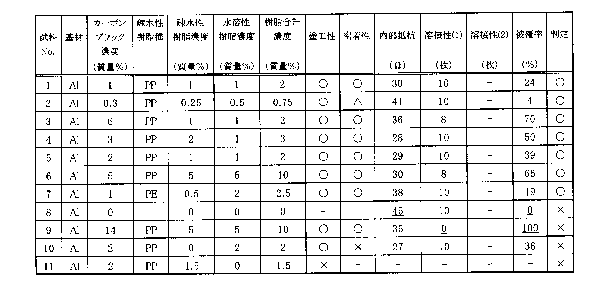
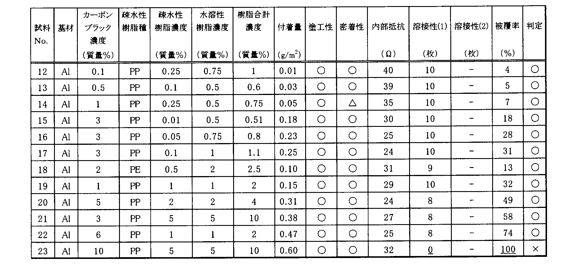
- Tables 1 and 2 show a list of characteristics evaluation results and pass / fail judgment results of samples prepared using an Al foil as a base material.
- the determination result “ ⁇ ” indicates good and “x” indicates failure.
- numerical values determined to be defective are shown with an underline.
- sample No. 1-No. 7 shows that all evaluations (coating properties, adhesion, internal resistance, weldability and coverage) are good, and that carbon black (conductive material) is arranged in islands by observation using SEM. confirmed.
- the SEM (scanning electron microscope) photograph shown in FIG. 1 is a photograph of the surface of a sample, and in FIG. 5, one graduation shown at the lower right is 10 ⁇ m.
- Sample No. 8 is a comparative example in which a battery cell is manufactured using an electrode using a current collector made of only an Al foil as a base material without using carbon black (conductive material).
- the internal resistance of the battery cell was 45 ⁇ .
- Sample No. 9 is a case where the density
- Sample No. 10 is the result when only the water-soluble resin is used without using the hydrophobic resin.
- the coverage is 36%, which is in the range of 1 to 80%, and the coating property, the effect of reducing internal resistance and weldability are good, but since no hydrophobic resin is used, sufficient adhesion is obtained. There wasn't.
- Sample No. 11 is a result when only a hydrophobic resin is used without using a water-soluble resin. Since a water-soluble resin was not used, a slurry containing carbon black could not be applied satisfactorily on the surface of the substrate.
- sample No. 12-No. No. 22 is good in all evaluations (coating property, adhesion, internal resistance, weldability (1) and coverage).
- adhesion amount of the conductive material 0.01 g / m 2 or more
- the internal resistance of the battery becomes 90% or less of the internal resistance (45 ⁇ ) when the Al foil without the conductive material is used, and the contact resistance Can be confirmed to decrease significantly.
- Sample No. No. 23 is a case where the concentration of carbon black (conductive material) in the slurry is as high as 10% by mass. For this reason, the conductive material on the surface of the base material has a large amount of adhesion, does not have an island structure, and the weldability (1) is not excellent.
- Table 3 shows a list of characteristics evaluation results and pass / fail judgment results of samples prepared using Cu foil as a base material.
- the determination result “ ⁇ ” indicates good and “ ⁇ ” indicates failure.
- numerical values determined to be defective are underlined.
- sample no. 24-No. No. 28 is good in all evaluations (coating property, adhesion, internal resistance, weldability (2) and coverage), and carbon black (conductive material) is arranged in an island shape by observation using SEM. I confirmed.
- Sample No. Reference numeral 29 is a comparative example in which a battery cell is manufactured using an electrode using a current collector made of only Cu foil as a base material without using carbon black (conductive substance).
- the contact resistance was 108 m ⁇ ⁇ cm 2 .
- Sample No. Reference numeral 30 denotes a case where the concentration of carbon black (conductive material) in the slurry is as high as 10% by mass. For this reason, since the coverage of carbon black was as high as 100% and it did not have an island structure, weldability (2) was not excellent.
- Sample No. 31 is a result when only a hydrophobic resin is used without using a water-soluble resin. Since a water-soluble resin was not used, a slurry containing carbon black could not be applied satisfactorily on the surface of the substrate.
- Sample No. 32 is a result when only a hydrophilic resin is used without using a hydrophobic resin.
- the coverage is 45%, which is in the range of 1 to 80%, and the coating and contact resistance reduction effect and weldability (2) are good, but the adhesion is sufficient because no hydrophobic resin is used. Sex was not obtained.
- the conductive material is arranged in an island shape on the surface of the metal foil as the base material, and the amount of the conductive material attached is limited.
- the contact resistance with the active material layer can be reduced.
- this island-like structure is closely attached to the metal foil that is the base material, and the island-like structure is formed in the manufacturing process before handling the electrode material or before coating the active material layer Therefore, the effect of reducing the contact resistance by the island structure is not impaired.
- an island-like structure of a conductive material can be formed with good adhesion on the surface of a base material, so that weldability such as a tab is good, and contact resistance with an active material layer Can be manufactured with stable quality. Further, since an aqueous solution is used, it is possible to reduce the environmental load due to solvent vapor in the manufacturing process. Moreover, according to the method for producing an electrode material according to the present invention, since carbon is used at a suitable concentration as a conductive substance, an electrode material on which a suitable island-like structure is formed can be produced.
- the method for producing an electrode material according to the present invention since a resin is used at a suitable concentration, it is possible to produce an electrode material with good quality. According to the electrode of the present invention, the contact resistance between the electrode material and the active material layer can be reduced. Moreover, according to the secondary battery which concerns on this invention, internal resistance can be reduced.
- Electrode 11 Positive electrode (electrode) 12 Negative electrode (electrode) 13 Separator 14 Electrolyte 20 Lithium ion secondary battery (secondary battery)
Landscapes
- Chemical & Material Sciences (AREA)
- Engineering & Computer Science (AREA)
- Materials Engineering (AREA)
- Chemical Kinetics & Catalysis (AREA)
- Electrochemistry (AREA)
- General Chemical & Material Sciences (AREA)
- Composite Materials (AREA)
- Cell Electrode Carriers And Collectors (AREA)
- Battery Electrode And Active Subsutance (AREA)
Abstract
Description
また、本発明に係る二次電池によれば、内部抵抗を低減することができる。
[集電体の構造]
本実施形態に係る集電体の構造について、図1を参照して説明する。
本実施形態に係る集電体(電極材料)1は、金属箔からなる基材1aと、基材1aの表面に島状に配置された導電物質1bとからなる。また、導電物質1bは、基材1aの両面に配置されている。なお、導電物質1bは、基材1aの片面に配置してもよい。
基材1aは、二次電池用の電極材料として一般的に用いられるアルミニウム(Al)や銅(Cu)などの金属を用いることができる。二次電池用電極材料として使用する際は、基材1aは一般的に厚さが5~50μm程度の箔状で使用される。本実施形態に係る集電体の製造方法において、圧延工程を実施する場合は、板状または厚肉の箔状の基材1aに導電物質1bを含む溶液を塗布して乾燥した後、圧延を施し薄肉化するようにしてもよい。
なお、基材1aは特定の組成のAlやCuなどに限定されるものではなく、電極に用いられる場合に、その電極の使用環境に適した各種の純金属やその合金を用いることができる。
導電物質1bは、300μm四方の視野で観察した際に、基材1aの表面の1~80%を被覆するように島状に配置され、基材1aとともに構成する集電体1と活物質層(図2参照)との間の接触抵抗を低減するものである。
導電物質1bとしては、炭素系の導電材料(炭素)を用いることができる。炭素系の導電材料としては、天然または人造の結晶性グラファイト、膨張化黒鉛、人造黒鉛、熱分解黒鉛またはアセチレンブラックなどの各種のカーボンブラックを用いることができる。
バインダー(不図示)は、導電物質1bからなる島状構造と基材1aの表面との密着性を向上させるための疎水性樹脂と、この疎水性樹脂および導電物質1bを含む溶液を基材1aの表面に塗布する際の塗布性を向上させるための水溶性樹脂とから構成される。これによって、基材1aと導電物質1bの島状構造との密着性がよく、この島状構造が基材1aの表面に一様に分布して形成される。
次に、図2を参照して、本実施形態に係る集電体1を用いたリチウムイオン二次電池の電極の構成について説明する。
次に、図3を参照(適宜図2参照)して、本実施形態に係る集電体1を使用した電極10を用いたリチウムイオン二次電池の構成について説明する。
また、セパレータ13および電解液14は、それぞれ公知の材料を用いて構成することができる。セパレータ13としては、例えば、厚さ20~30μmのポリエチレン系のマイクロポーラスフィルムを用いることができる。また、電解液14としては、例えば、プロピレンカーボネート、エチレンカーボネートなどの有機溶剤にLiPF6、LiBF4などの電解質を溶解させた非水系電解液を用いることができる。
[製造方法]
図4に示したように、本実施形態における集電体1の製造方法は、塗布工程S1と、乾燥工程S2とがこの順で含まれる。
以下、塗布工程について詳細に説明する。
まず、塗布工程S1について説明する。
導電物質1bを理想的な島状の構造に凝集させるには、スラリーに含まれる導電物質1bの粒径および濃度、ならびにバインダーである疎水性樹脂および水溶性樹脂の濃度を調節することが有効である。これら導電物質1bの粒径および濃度、ならびにバインダーの濃度を調節すると、スラリーの粘度が変化するため、塗工性および、乾燥後の導電物質1bの分布に変化が生じる。導電物質1bとして炭素を用いた場合、平均粒径が0.01~1μmの炭素を用いることが好ましい。また炭素が、スラリー中に0.1~7質量%含まれる状態が好ましい。平均粒径を0.01μm以上、および濃度(含有量)を7質量%以下とすることにより、スラリーの粘度が上昇し過ぎず、炭素粒子同士の凝集が大きくなり過ぎないため、理想的な島状の構造を得ることができる。また、導電物質1bである炭素の平均粒径を1μm以下、および炭素の濃度を0.1質量%以上とすることにより、島状の構造が形成されるとともに、導電物質1bである炭素と基材1aである金属箔との接触点が十分にあり、集電体1と活物質層2(図2参照)との間の接触抵抗を低減する効果を得ることができる。
なお、疎水性樹脂の濃度は、0.01質量%以上、かつ11質量%程度以下とすることが好ましく、0.10質量%以上とすることがより好ましく、0.25質量%以上とすることが更に好ましい。
なお、水溶性樹脂の濃度は、0.25質量%以上、かつ11質量%程度以下とすることが好ましい。
乾燥工程S2は、塗布工程S1の後に、溶媒を蒸散させるための工程である。乾燥工程S2は、室温にて乾燥させるようにしてもよいし、必要に応じて熱処理炉などを用いた加熱乾燥を行うようにしてもよい。
更に密着性・接触抵抗を向上させるため、乾燥工程S2の後で、必要に応じて圧着や圧延をおこなうようにしてもよい。なお、圧着や圧延の方法としては、各種圧延機やロールプレス機を用いることができる。
(基材)
基材として、1000系のAl合金製の、厚さ15μmのAl箔、または99.99%の純銅製の、厚さ20μmのCu箔を使用した。
なお、後記する表1~表3において、各試料がAl箔とCu箔の何れを用いたかを、それぞれ「Al」または「Cu」で基材の欄に示した。
疎水性樹脂として、ポリプロピレン(PP)またはポリエチレン(PE)を用いた水系エマルジョン溶液を調整し、調整した水系エマルジョン溶液を純水で希釈して使用した。また、比較のため、疎水性樹脂を使用しない試料も作製した。
水溶性樹脂としてカルボキシメチルセルロース(CMC)ナトリウム塩を用いた。また、比較のため、水溶性樹脂を使用しない試料も作製した。
導電物質として、平均粒径が0.06μmのカーボンブラック(東海カーボン社製のトーカブラック#4300)を用いた。
塗工においては、溶媒を純水とし、各試料について表1~表3に示したカーボンブラック(導電物質)の濃度、疎水性樹脂の種類と濃度、および水溶性樹脂の濃度で作製した溶液(スラリー)を、バーコーターを用いて基材の表面に塗工した。
なお、溶接性評価用の試料には、基材の両面にカーボンブラックを含有する前記スラリーを塗工し、他の項目評価用の試料には、基材の片面にスラリーを塗工した。
カーボンブラックを含有するスラリーを基材の表面に塗布した後、オーブン中に150℃で1分間保持して乾燥を行った。
(塗工性評価)
塗工性評価は前記した塗布工程において、塗工したスラリーが基材上で水はじきのため水玉状となったものを不良(×)、水はじきがなく、塗工したスラリーが基材の表面を均一に覆うことができたものを良好(○)とした。
粘着力が2N/40mm、幅40mm、長さ120mm、厚さ0.08mmの粘着テープを貼り付けたローラ(直径90mm、幅50mm、質量700g)を、試料の表面で100mm転がし、剥離したカーボンブラックの面積を見積もった。カーボンブラックの剥離が全く無いときを優良(○)、20%以下の剥離が観察されたときを良好(△)、それ以上の剥離が観察されたときを不良(×)とした。
導電物質(炭素)の被覆率は、日立製作所製の電界放射型走査電子顕微鏡(FE-SEM)SU-70を用いて作製した試料の表面を倍率300倍にて撮影し、撮影した視野中に含まれる炭素による基材表面の被覆面積を画像処理により算出して求めた。
基材としてAl箔を使用した場合の溶接性の評価は、厚さ15μmのAl箔の両面に、カーボンブラック(導電物質)が形成された試料を10枚重ね、その上下(両端)に30μm厚のアルミ箔、及び250μmのアルミ板を配し、一定圧力を加えた状態で溶接を行い、8枚以上溶接されたものを良好、7枚以下しか溶接されなかったものを不良と判定した。なお、溶接には、ソノボンド社製の超音波溶接機MH2026/CLF2500を用い、圧力0.28MPa、出力400W、エネルギー20Jの条件で、通電時間70μ秒にて溶接を行った。
基材としてCu箔を使用した場合の溶接性の評価は、厚さ20μmのCu箔の両面に、カーボンブラック(導電物質)が形成された試料を10枚重ね、一定圧力を加えた状態で溶接を行い、8枚以上溶接されたものを良好、7枚以下しか溶接されなかったものを不良と判定した。なお、溶接には、Yokodai.jp社製のスポット溶接機HSW-02Aを用い、電圧25V、通電時間500μ秒にて溶接を行った。
カーボンブラック(導電物質)が形成された試料の両面に、コバルト酸リチウム、アセチレンブラックおよびPVdF(ポリフッ化ビニリデン)を混合したスラリーを、片面当たり厚さ25μmで塗工し、正電極を作製した。また、負電極として、Al箔の両面にグラファイトを片面当たり厚さ35μmにて塗工したものを用いた。
基材としてCu箔を使用した場合の接触抵抗(抵抗低減効果)については、以下のようにして測定を行った。
試料の両面を2枚のカーボンクロスで挟み、更にその外側を接触面積1cm2の2枚の銅電極で挟み、この銅電極に1kgf(9.8N)の荷重をかけて加圧する。そして、直流電流電源を用いて7.4mAの電流を通電し、カーボンクロス間に加わる電圧を電圧計で測定した。接触抵抗は、前記した電流値、接触面積および測定した電圧から算出して求めた。同様の測定を基材のみを用いて行い、基材のみの場合と比較して接触抵抗が低減するものを接触抵抗の低減効果があると判定した。なお、何ら表面処理を施さない、基材であるCu箔のみの場合の接触抵抗は、約100[mΩ・cm2(ミリオーム平方センチメートル)]であった。
導電物質の基材における単位面積当たりの付着量は、以下の手順により測定した。なお、本実施例において、基材における単位面積当たりの導電物質の付着量とは、基材の片面の単位面積当たりの付着量であり、導電物質であるカーボンブラックと、バインダーである水溶性樹脂および疎水性樹脂とを合計した付着量である。
まず、導電物質、水溶性樹脂及び疎水性樹脂を含有する溶液を基材に塗布して乾燥した試料の質量を測定する。次に、試料の表面を水で拭き取り、乾燥させた。続いて、同じ試料の表面をアルコールで拭き取り、箔上に付着している親水性樹脂、親油性樹脂および導電物質を除去した。樹脂および導電物質を除去したあとの試料の質量を測定した。導電物質除去前と導電物質除去後の試料の質量差を、基材の面積で除することによって、導電物質の基材上における単位面積当たりの付着量を算出した。
なお、本実施例においては、基材(すなわち試料)は、50mm角の大きさ(すなわち、面積が2500mm2)のAl箔またはCu箔を用いた。
なお、表1および表2において、判定結果が「○」は良好を、「×」は不良を示す。また、表1および表2において、不良と判定された数値に下線を付して示した。

本出願は、2011年10月25日出願の日本特許出願(特願2011-234320)及び2012年9月5日出願の日本特許出願(特願2012-194663)に基づくものであり、その内容はここに参照として取り込まれる。
本発明に係る電極材料の製造方法によれば、基材の表面に導電物質の島状構造を密着性よく形成できるため、タブなどの溶接性が良好で、活物質層との間の接触抵抗を低減できる電極材料を安定した品質で製造することができる。また、水系の溶液を用いるため、製造工程における溶媒蒸気などによる環境負荷を低減することができる。
また、本発明に係る電極材料の製造方法によれば、導電物質として好適な濃度でカーボンを用いるため、好適な島状構造が形成される電極材料を製造することができる。
更にまた、本発明に係る電極材料の製造方法によれば、好適な濃度で樹脂を用いるため、良好な品質の電極材料を製造することができる。
本発明に係る電極によれば、電極材料と活物質層との間の接触抵抗を低減することができる。
また、本発明に係る二次電池によれば、内部抵抗を低減することができる。
1a 基材
1b 導電物質
2 活物質層
10 電極
11 正電極(電極)
12 負電極(電極)
13 セパレータ
14 電解液
20 リチウムイオン二次電池(二次電池)
Claims (7)
- 金属箔を含む基材と、この基材の少なくとも一方の表面に設けた導電物質とを備えた電極材料であって、
300μm四方の視野にて観察した際に、前記導電物質が前記基材の表面に島状に配置され、前記導電物質が、疎水性樹脂および水溶性樹脂とともに前記基材の表面に固着していることを特徴とする電極材料。 - 前記導電物質と前記水溶性樹脂と前記疎水性樹脂とを合計した前記基材の表面における単位面積当たりの付着量が、0.01~0.50g/m2であることを特徴とする請求項1に記載の電極材料。
- 請求項1に記載の電極材料の製造方法であって、
前記基材の表面に、前記導電物質と、前記水溶性樹脂と、前記疎水性樹脂の水系エマルジョン溶液と、を含有するスラリーを塗布する塗布工程と、前記スラリーを乾燥させる乾燥工程とをこの順で含み、前記スラリーを前記基材に塗布する前ないし塗布した後に、前記導電物質を前記スラリー中で凝集させることを特徴とする電極材料の製造方法。 - 前記導電物質は炭素を含有し、前記スラリーにおける前記炭素の含有量が0.1~7質量%であることを特徴とする請求項3に記載の電極材料の製造方法。
- 前記スラリーは、前記水溶性樹脂の含有量が0.25質量%以上であり、前記疎水性樹脂の含有量が0.01質量%以上であり、かつ、前記水溶性樹脂の含有量および前記疎水性樹脂の含有量の合計が11質量%以下であることを特徴とする請求項3に記載の電極材料の製造方法。
- 二次電池の電極であって、
請求項1に記載の電極材料と、
前記電極材料の前記導電物質の表面に形成された活物質層とを備えていることを特徴とする二次電池の電極。 - 正電極および負電極を有する二次電池であって、前記正電極または前記負電極の少なくとも一方は、請求項6に記載の電極であることを特徴とする二次電池。
Priority Applications (5)
| Application Number | Priority Date | Filing Date | Title |
|---|---|---|---|
| US14/353,364 US9685662B2 (en) | 2011-10-25 | 2012-10-22 | Electrode material, electrode material manufacturing method, electrode, and secondary battery |
| IN3055CHN2014 IN2014CN03055A (ja) | 2011-10-25 | 2012-10-22 | |
| EP12843029.5A EP2772973B1 (en) | 2011-10-25 | 2012-10-22 | Electrode material, electrode material manufacturing method, electrode, and secondary battery |
| CN201280052273.XA CN103891020B (zh) | 2011-10-25 | 2012-10-22 | 电极材料、电极材料的制造方法、电极和二次电池 |
| KR1020147010711A KR101624432B1 (ko) | 2011-10-25 | 2012-10-22 | 전극 재료, 전극 재료의 제조 방법, 전극 및 이차 전지 |
Applications Claiming Priority (4)
| Application Number | Priority Date | Filing Date | Title |
|---|---|---|---|
| JP2011-234320 | 2011-10-25 | ||
| JP2011234320 | 2011-10-25 | ||
| JP2012194663A JP5281706B2 (ja) | 2011-10-25 | 2012-09-05 | 集電体、集電体の製造方法、電極および二次電池 |
| JP2012-194663 | 2012-09-05 |
Publications (1)
| Publication Number | Publication Date |
|---|---|
| WO2013061914A1 true WO2013061914A1 (ja) | 2013-05-02 |
Family
ID=48167746
Family Applications (1)
| Application Number | Title | Priority Date | Filing Date |
|---|---|---|---|
| PCT/JP2012/077217 Ceased WO2013061914A1 (ja) | 2011-10-25 | 2012-10-22 | 電極材料、電極材料の製造方法、電極および二次電池 |
Country Status (8)
| Country | Link |
|---|---|
| US (1) | US9685662B2 (ja) |
| EP (1) | EP2772973B1 (ja) |
| JP (1) | JP5281706B2 (ja) |
| KR (1) | KR101624432B1 (ja) |
| CN (1) | CN103891020B (ja) |
| IN (1) | IN2014CN03055A (ja) |
| TW (1) | TWI514657B (ja) |
| WO (1) | WO2013061914A1 (ja) |
Families Citing this family (11)
| Publication number | Priority date | Publication date | Assignee | Title |
|---|---|---|---|---|
| KR101452878B1 (ko) * | 2012-08-29 | 2014-10-22 | 쇼와 덴코 가부시키가이샤 | 축전 디바이스 및 그 제조 방법 |
| JP5707605B2 (ja) * | 2013-02-21 | 2015-04-30 | 東洋インキScホールディングス株式会社 | 導電性組成物、蓄電デバイス用下地層付き集電体、蓄電デバイス用電極、及び蓄電デバイス |
| JP6539978B2 (ja) * | 2014-10-16 | 2019-07-10 | 東洋インキScホールディングス株式会社 | 導電性組成物、蓄電デバイス用電極、及び蓄電デバイス |
| US20190027770A1 (en) * | 2016-01-07 | 2019-01-24 | Sumitomo Electric Industries, Ltd. | Redox flow battery, electrode for redox flow battery, and electrode characteristic evaluation method |
| JP6956323B2 (ja) | 2016-03-22 | 2021-11-02 | パナソニックIpマネジメント株式会社 | リード部材付き電気化学デバイス用正極およびその製造方法ならびに電気化学デバイス |
| JP7009048B2 (ja) * | 2016-06-15 | 2022-01-25 | 東洋インキScホールディングス株式会社 | 導電性組成物、蓄電デバイス用下地層付き集電体、蓄電デバイス用電極、及び蓄電デバイス |
| KR102619895B1 (ko) | 2016-08-01 | 2024-01-02 | 삼성에스디아이 주식회사 | 이차 전지 |
| JP6879044B2 (ja) * | 2017-05-12 | 2021-06-02 | 東洋インキScホールディングス株式会社 | 非水電解質二次電池用下地層付き集電体、非水電解質二次電池用電極及び非水電解質二次電池 |
| CN113346069B (zh) * | 2018-02-11 | 2022-06-10 | 宁德时代新能源科技股份有限公司 | 正极材料及其制备方法、电池 |
| WO2022050046A1 (ja) * | 2020-09-02 | 2022-03-10 | 株式会社村田製作所 | 二次電池 |
| CN114948194B (zh) * | 2022-05-24 | 2025-11-28 | 成都仕康美医疗器械有限公司 | 一种医用负极板 |
Citations (8)
| Publication number | Priority date | Publication date | Assignee | Title |
|---|---|---|---|---|
| JPH06260164A (ja) * | 1993-02-26 | 1994-09-16 | Japan Storage Battery Co Ltd | 非水電解質二次電池 |
| JPH0997625A (ja) | 1995-09-29 | 1997-04-08 | Seiko Instr Inc | 非水電解質二次電池およびその製造方法 |
| JP2001351612A (ja) | 2000-06-06 | 2001-12-21 | Matsushita Battery Industrial Co Ltd | 非水電解液二次電池 |
| JP2002352796A (ja) * | 2001-05-22 | 2002-12-06 | Fuji Heavy Ind Ltd | リチウム二次電池用正極およびリチウム二次電池 |
| JP2007226969A (ja) | 2005-02-10 | 2007-09-06 | Showa Denko Kk | 二次電池用集電体、二次電池用正極、二次電池用負極、二次電池及びそれらの製造方法 |
| JP2009252396A (ja) * | 2008-04-02 | 2009-10-29 | Toyota Motor Corp | リチウム二次電池の正極およびその製造方法 |
| JP2009266466A (ja) * | 2008-04-23 | 2009-11-12 | Nec Tokin Corp | 非水電解液二次電池 |
| JP2010135338A (ja) | 2005-02-10 | 2010-06-17 | Showa Denko Kk | 二次電池用集電体、二次電池用正極、二次電池用負極、二次電池及びそれらの製造方法 |
Family Cites Families (16)
| Publication number | Priority date | Publication date | Assignee | Title |
|---|---|---|---|---|
| US4581116A (en) * | 1984-12-04 | 1986-04-08 | The Dow Chemical Company | Gas diffusion composite electrode having novel hydrophilic layer |
| US5542163A (en) * | 1993-04-19 | 1996-08-06 | Chang; On K. | Electrically-conducting adhesion-promoter |
| JPH10144298A (ja) | 1996-11-15 | 1998-05-29 | Sanyo Electric Co Ltd | リチウム二次電池 |
| US6838205B2 (en) * | 2001-10-10 | 2005-01-04 | Lynntech, Inc. | Bifunctional catalytic electrode |
| JP2003249223A (ja) * | 2002-02-26 | 2003-09-05 | Matsushita Electric Ind Co Ltd | リチウムイオン二次電池およびその製造方法 |
| US6855459B2 (en) * | 2002-06-20 | 2005-02-15 | Samsung Sdi Co., Ltd | Electrode for rechargeable lithium battery, method of preparing same and rechargeable lithium battery having the same |
| DE60230979D1 (de) * | 2002-07-31 | 2009-03-12 | Umicore Ag & Co Kg | Wässrige Katalysatortinten und ihre Verwendung für die Herstellung von mit Katalysator beschichteten Substraten |
| JP2006004739A (ja) * | 2004-06-17 | 2006-01-05 | Toyota Motor Corp | リチウム二次電池と該電池に備えられる正極及びその製造方法 |
| TWI483446B (zh) * | 2005-02-10 | 2015-05-01 | 昭和電工股份有限公司 | A battery collector, a battery positive electrode, a battery negative electrode, a battery, and a manufacturing method |
| KR101179378B1 (ko) | 2005-02-10 | 2012-09-03 | 쇼와 덴코 가부시키가이샤 | 이차전지용 집전기, 이차전지 양극, 이차전지 음극, 이차전지 및 그들의 제조 방법 |
| US7749631B2 (en) | 2005-06-01 | 2010-07-06 | Gm Global Technology Operations, Inc. | Fuel cell separator plate coating |
| TWI467840B (zh) * | 2005-09-02 | 2015-01-01 | A123 Systems Inc | 奈米組成電極以及其相關裝置 |
| JP5215307B2 (ja) | 2007-07-18 | 2013-06-19 | 第一工業製薬株式会社 | リチウム二次電池 |
| JP2010086866A (ja) * | 2008-10-01 | 2010-04-15 | Toyota Motor Corp | 電極シートおよびその製造方法 |
| JP4487220B1 (ja) | 2009-01-26 | 2010-06-23 | トヨタ自動車株式会社 | リチウム二次電池用正極およびその製造方法 |
| JP5287601B2 (ja) * | 2009-08-25 | 2013-09-11 | 日本ゼオン株式会社 | 電気化学素子用電極の製造方法、電気化学素子用電極及び電気化学素子 |
-
2012
- 2012-09-05 JP JP2012194663A patent/JP5281706B2/ja not_active Expired - Fee Related
- 2012-10-22 CN CN201280052273.XA patent/CN103891020B/zh not_active Expired - Fee Related
- 2012-10-22 US US14/353,364 patent/US9685662B2/en not_active Expired - Fee Related
- 2012-10-22 KR KR1020147010711A patent/KR101624432B1/ko not_active Expired - Fee Related
- 2012-10-22 EP EP12843029.5A patent/EP2772973B1/en not_active Not-in-force
- 2012-10-22 IN IN3055CHN2014 patent/IN2014CN03055A/en unknown
- 2012-10-22 WO PCT/JP2012/077217 patent/WO2013061914A1/ja not_active Ceased
- 2012-10-24 TW TW101139262A patent/TWI514657B/zh not_active IP Right Cessation
Patent Citations (9)
| Publication number | Priority date | Publication date | Assignee | Title |
|---|---|---|---|---|
| JPH06260164A (ja) * | 1993-02-26 | 1994-09-16 | Japan Storage Battery Co Ltd | 非水電解質二次電池 |
| JPH0997625A (ja) | 1995-09-29 | 1997-04-08 | Seiko Instr Inc | 非水電解質二次電池およびその製造方法 |
| JP2001351612A (ja) | 2000-06-06 | 2001-12-21 | Matsushita Battery Industrial Co Ltd | 非水電解液二次電池 |
| JP2002352796A (ja) * | 2001-05-22 | 2002-12-06 | Fuji Heavy Ind Ltd | リチウム二次電池用正極およびリチウム二次電池 |
| JP2007226969A (ja) | 2005-02-10 | 2007-09-06 | Showa Denko Kk | 二次電池用集電体、二次電池用正極、二次電池用負極、二次電池及びそれらの製造方法 |
| JP2010135338A (ja) | 2005-02-10 | 2010-06-17 | Showa Denko Kk | 二次電池用集電体、二次電池用正極、二次電池用負極、二次電池及びそれらの製造方法 |
| JP2011086636A (ja) * | 2005-02-10 | 2011-04-28 | Showa Denko Kk | 二次電池用集電体形成用のペースト、二次電池用集電体およびその製造方法、二次電池用電極、二次電池 |
| JP2009252396A (ja) * | 2008-04-02 | 2009-10-29 | Toyota Motor Corp | リチウム二次電池の正極およびその製造方法 |
| JP2009266466A (ja) * | 2008-04-23 | 2009-11-12 | Nec Tokin Corp | 非水電解液二次電池 |
Non-Patent Citations (1)
| Title |
|---|
| See also references of EP2772973A4 |
Also Published As
| Publication number | Publication date |
|---|---|
| EP2772973B1 (en) | 2017-01-04 |
| CN103891020A (zh) | 2014-06-25 |
| TW201334274A (zh) | 2013-08-16 |
| US9685662B2 (en) | 2017-06-20 |
| KR20140072117A (ko) | 2014-06-12 |
| EP2772973A4 (en) | 2015-07-15 |
| KR101624432B1 (ko) | 2016-05-25 |
| JP5281706B2 (ja) | 2013-09-04 |
| JP2013110098A (ja) | 2013-06-06 |
| US20140287319A1 (en) | 2014-09-25 |
| CN103891020B (zh) | 2016-08-17 |
| EP2772973A1 (en) | 2014-09-03 |
| TWI514657B (zh) | 2015-12-21 |
| IN2014CN03055A (ja) | 2015-07-03 |
Similar Documents
| Publication | Publication Date | Title |
|---|---|---|
| JP5281706B2 (ja) | 集電体、集電体の製造方法、電極および二次電池 | |
| JP2018142431A (ja) | 硫化物全固体電池用負極、及び、硫化物全固体電池、並びに当該硫化物全固体電池の製造方法 | |
| WO2013018473A1 (ja) | 被覆層付き金属箔及びその製造方法、二次電池用電極及びその製造方法並びにリチウムイオン二次電池 | |
| WO2022230661A1 (ja) | 二次電池用負極、二次電池、及び二次電池用負極の製造方法 | |
| JP2020035682A (ja) | 非水電解質二次電池及び非水電解質二次電池の製造方法 | |
| JP5144821B1 (ja) | 電極材料の製造方法 | |
| JP5325326B2 (ja) | 集電体、電極、二次電池、および二次電池の製造方法 | |
| JP5140779B1 (ja) | 電極材料 | |
| TWI514651B (zh) | Electrode material, electrode and secondary battery | |
| CN115050919B (zh) | 二次电池用电极的制造方法及二次电池的制造方法 |
Legal Events
| Date | Code | Title | Description |
|---|---|---|---|
| 121 | Ep: the epo has been informed by wipo that ep was designated in this application |
Ref document number: 12843029 Country of ref document: EP Kind code of ref document: A1 |
|
| ENP | Entry into the national phase |
Ref document number: 20147010711 Country of ref document: KR Kind code of ref document: A |
|
| WWE | Wipo information: entry into national phase |
Ref document number: 14353364 Country of ref document: US |
|
| REEP | Request for entry into the european phase |
Ref document number: 2012843029 Country of ref document: EP |
|
| WWE | Wipo information: entry into national phase |
Ref document number: 2012843029 Country of ref document: EP |
|
| NENP | Non-entry into the national phase |
Ref country code: DE |