WO2013062003A1 - 薬品注入制御方法及び薬品注入制御装置 - Google Patents
薬品注入制御方法及び薬品注入制御装置 Download PDFInfo
- Publication number
- WO2013062003A1 WO2013062003A1 PCT/JP2012/077473 JP2012077473W WO2013062003A1 WO 2013062003 A1 WO2013062003 A1 WO 2013062003A1 JP 2012077473 W JP2012077473 W JP 2012077473W WO 2013062003 A1 WO2013062003 A1 WO 2013062003A1
- Authority
- WO
- WIPO (PCT)
- Prior art keywords
- chemical injection
- injection rate
- water
- water quality
- basic
- Prior art date
- Legal status (The legal status is an assumption and is not a legal conclusion. Google has not performed a legal analysis and makes no representation as to the accuracy of the status listed.)
- Ceased
Links
Images




Classifications
-
- C—CHEMISTRY; METALLURGY
- C02—TREATMENT OF WATER, WASTE WATER, SEWAGE, OR SLUDGE
- C02F—TREATMENT OF WATER, WASTE WATER, SEWAGE, OR SLUDGE
- C02F1/00—Treatment of water, waste water, or sewage
- C02F1/52—Treatment of water, waste water, or sewage by flocculation or precipitation of suspended impurities
-
- C—CHEMISTRY; METALLURGY
- C02—TREATMENT OF WATER, WASTE WATER, SEWAGE, OR SLUDGE
- C02F—TREATMENT OF WATER, WASTE WATER, SEWAGE, OR SLUDGE
- C02F1/00—Treatment of water, waste water, or sewage
- C02F1/008—Control or steering systems not provided for elsewhere in subclass C02F
-
- C—CHEMISTRY; METALLURGY
- C02—TREATMENT OF WATER, WASTE WATER, SEWAGE, OR SLUDGE
- C02F—TREATMENT OF WATER, WASTE WATER, SEWAGE, OR SLUDGE
- C02F1/00—Treatment of water, waste water, or sewage
- C02F1/52—Treatment of water, waste water, or sewage by flocculation or precipitation of suspended impurities
- C02F1/5209—Regulation methods for flocculation or precipitation
-
- C—CHEMISTRY; METALLURGY
- C02—TREATMENT OF WATER, WASTE WATER, SEWAGE, OR SLUDGE
- C02F—TREATMENT OF WATER, WASTE WATER, SEWAGE, OR SLUDGE
- C02F1/00—Treatment of water, waste water, or sewage
- C02F1/001—Processes for the treatment of water whereby the filtration technique is of importance
- C02F1/004—Processes for the treatment of water whereby the filtration technique is of importance using large scale industrial sized filters
-
- C—CHEMISTRY; METALLURGY
- C02—TREATMENT OF WATER, WASTE WATER, SEWAGE, OR SLUDGE
- C02F—TREATMENT OF WATER, WASTE WATER, SEWAGE, OR SLUDGE
- C02F1/00—Treatment of water, waste water, or sewage
- C02F1/28—Treatment of water, waste water, or sewage by sorption
- C02F1/283—Treatment of water, waste water, or sewage by sorption using coal, charred products, or inorganic mixtures containing them
-
- C—CHEMISTRY; METALLURGY
- C02—TREATMENT OF WATER, WASTE WATER, SEWAGE, OR SLUDGE
- C02F—TREATMENT OF WATER, WASTE WATER, SEWAGE, OR SLUDGE
- C02F1/00—Treatment of water, waste water, or sewage
- C02F1/44—Treatment of water, waste water, or sewage by dialysis, osmosis or reverse osmosis
-
- C—CHEMISTRY; METALLURGY
- C02—TREATMENT OF WATER, WASTE WATER, SEWAGE, OR SLUDGE
- C02F—TREATMENT OF WATER, WASTE WATER, SEWAGE, OR SLUDGE
- C02F2209/00—Controlling or monitoring parameters in water treatment
- C02F2209/001—Upstream control, i.e. monitoring for predictive control
-
- C—CHEMISTRY; METALLURGY
- C02—TREATMENT OF WATER, WASTE WATER, SEWAGE, OR SLUDGE
- C02F—TREATMENT OF WATER, WASTE WATER, SEWAGE, OR SLUDGE
- C02F2209/00—Controlling or monitoring parameters in water treatment
- C02F2209/003—Downstream control, i.e. outlet monitoring, e.g. to check the treating agents, such as halogens or ozone, leaving the process
-
- C—CHEMISTRY; METALLURGY
- C02—TREATMENT OF WATER, WASTE WATER, SEWAGE, OR SLUDGE
- C02F—TREATMENT OF WATER, WASTE WATER, SEWAGE, OR SLUDGE
- C02F2209/00—Controlling or monitoring parameters in water treatment
- C02F2209/005—Processes using a programmable logic controller [PLC]
- C02F2209/006—Processes using a programmable logic controller [PLC] comprising a software program or a logic diagram
-
- C—CHEMISTRY; METALLURGY
- C02—TREATMENT OF WATER, WASTE WATER, SEWAGE, OR SLUDGE
- C02F—TREATMENT OF WATER, WASTE WATER, SEWAGE, OR SLUDGE
- C02F2209/00—Controlling or monitoring parameters in water treatment
- C02F2209/02—Temperature
-
- C—CHEMISTRY; METALLURGY
- C02—TREATMENT OF WATER, WASTE WATER, SEWAGE, OR SLUDGE
- C02F—TREATMENT OF WATER, WASTE WATER, SEWAGE, OR SLUDGE
- C02F2209/00—Controlling or monitoring parameters in water treatment
- C02F2209/06—Controlling or monitoring parameters in water treatment pH
-
- C—CHEMISTRY; METALLURGY
- C02—TREATMENT OF WATER, WASTE WATER, SEWAGE, OR SLUDGE
- C02F—TREATMENT OF WATER, WASTE WATER, SEWAGE, OR SLUDGE
- C02F2209/00—Controlling or monitoring parameters in water treatment
- C02F2209/07—Alkalinity
-
- C—CHEMISTRY; METALLURGY
- C02—TREATMENT OF WATER, WASTE WATER, SEWAGE, OR SLUDGE
- C02F—TREATMENT OF WATER, WASTE WATER, SEWAGE, OR SLUDGE
- C02F2209/00—Controlling or monitoring parameters in water treatment
- C02F2209/11—Turbidity
Definitions
- the present invention relates to a chemical injection control method and apparatus in a water purification system.
- the water supply facilities take into account various factors, including the quality of raw water, the quality of purified water, the scale of the water purification facilities, the operational control, and the level of maintenance management technology.
- Water purification technology is selected and combined. For example, it is selected from a disinfection-only method, a slow filtration method, a rapid filtration method, and a membrane filtration method, and combined with advanced water purification treatment as required (Non-Patent Document 1).
- a water purification plant that employs a rapid filtration method is generally used to inject a flocculant and perform rapid stirring, a floc formation pond for growing agglomerates (floc), and a precipitate for removing flocs that have grown.
- a sedimentation basin and a filtration basin that removes particles and flocs that could not be settled are provided.
- chemicals such as powdered activated carbon and disinfectant (liquefied chlorine, sodium hypochlorite) are used in addition to the flocculant (sulfuric acid band, polyaluminum chloride, polymer flocculant, iron-based flocculant).
- the water treatment plant performs proper chemical treatment while monitoring the quality of raw water, purified water, and tap water.
- the important point of the water purification treatment by the rapid filtration method is to control the injection rate of the flocculant to an appropriate value according to the quality of the raw water and to form a floc with good sedimentation. If the agglomeration process is performed at an inappropriate injection rate, the loss of flocs from the sedimentation basin or the agglomeration failure will lead to an increase in the loss head (filter pit) of the filtration basin, an increase in the washing frequency, and from the filtration basin for fine particles. Problems such as leakage.
- a combination of activated carbon injection method and membrane filtration method can be taken. Furthermore, depending on conditions such as the type of membrane and permeation flux, an agglomeration process may be necessary, and therefore, a process flow incorporating a chemical injection process including an aggregating agent is often employed. In such a membrane filtration system, a flocculant is added to the water to be filtered in order to improve filterability and coarsen fine particles that can be fouling substances as they are to prevent clogging.
- FF control feedforward control
- FB control feedback control
- the appropriate flocculant injection rate varies depending on the turbidity, alkalinity, pH, water temperature, etc. of the raw water, and differs depending on the quality of the water source. Therefore, it cannot be uniquely determined using only the raw water turbidity as an index. Therefore, conventionally, in the water purification plant, the determination of the coagulation state, the determination of the coagulant injection rate, or the control thereof has been performed by the following method.
- FF control based on an injection rate arithmetic expression showing a relationship with an appropriate flocculant injection rate, using water quality such as turbidity, pH, alkalinity, and water temperature as raw parameters.
- This calculation formula is derived by an empirical method based on the jar test and sedimentation water turbidity of the facility.
- combination with FB control based on the measured value of sediment water turbidity, AI control by fuzzy or neuro so as to be close to the result of jar test by the operator and the operation results of the implementation facility are exemplified. Is done.
- Patent Documents 1 to 3 are cited as prior art documents disclosing the above FF control, FB control, or a combination thereof.
- the chemical injection rate is controlled in real time based on the agglomeration start time of particles in raw water.
- the optimum values of the coagulant injection rate, the pre-alkali agent injection rate, and the post-alkaline agent injection rate are calculated by multiple regression analysis, and the coagulant and alkali are calculated based on these injection rates.
- the injection amount of the agent is controlled.
- the injection rate of activated carbon is determined so as to obtain the target water quality.
- THMFP trihalomethane precursor
- the chemical injection control method of the present invention is a chemical injection control method for controlling the injection rate of chemicals into the raw water based on the quality of the raw water and the treated water of the water purification system, and the chemical injection rate is set in advance.
- Calculating the optimum chemical injection rate by correcting the chemical injection rate based on the deviation between the measured value of the water quality index of the treated water obtained by the operation of the chemical injection pump based on the target value of the water quality index, and Corresponding to the water quality index of the raw water by determining the partial regression coefficient of each explanatory variable in the multiple regression equation by performing multiple regression analysis with the optimal chemical injection rate as the target variable and one or more water quality indices as the explanatory variables
- the chemical injection rate is newly calculated by correcting the basic chemical injection rate based on the measured value of the water quality
- the chemical injection control device of the present invention is a chemical injection control device that controls the injection rate of chemicals into the raw water based on the quality of the raw water and the treated water of the water purification treatment system, and has a preset chemical injection rate.
- Optimal chemical injection rate to calculate the optimal chemical injection rate by correcting the chemical injection rate based on the deviation between the measured value of the treated water quality index obtained by the operation of the chemical injection pump based on the target value of the water quality index
- the raw water is determined by calculating a partial regression coefficient of each explanatory variable of the multiple regression equation by performing a multiple regression analysis using the calculation means and the optimal chemical injection rate as a target variable and using one or more water quality indicators as explanatory variables.
- Multiple regression analysis calculation means for deriving the calculation formula of the basic chemical injection rate corresponding to the water quality index of the water, and the basic chemical injection corresponding to the water quality index of the raw water by using the measured value of the raw water water quality index to the calculation formula
- the chemical injection rate is calculated by correcting the basic chemical injection rate based on the measured value of the water quality index of the treated water obtained by controlling the chemical injection pump based on the basic chemical injection rate and the basic chemical injection rate calculating means Is newly calculated and output as a control factor of the chemical injection pump, and provided with a chemical injection rate calculating means for use in the optimum chemical injection rate calculating means.
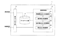
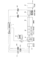
- the schematic block diagram of the chemical injection control apparatus which concerns on embodiment of this invention.
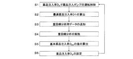
- the flowchart which showed the procedure of the chemical
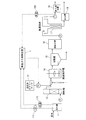
- the block diagram of the water purification system which concerns on Embodiment 1 of this invention.
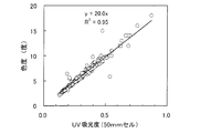
- the graph which showed the relationship between UV absorbance and chromaticity.
- the graph which showed the relationship between the optimal coagulant injection rate and the coagulant injection rate.
- the block diagram of the water purification system which concerns on Embodiment 2 of this invention.
- the block diagram of the water purification system which concerns on Embodiment 3 of this invention.
- the chemical injection control device 1 calculates the chemical injection rate for the raw water based on the measurement signal of the raw water and the treated water quality index of the water purification treatment system, and controls the chemical injection pump. Output as.
- the chemical injection rate is determined based on the deviation between the measured value of the treated water quality index obtained by the operation of the chemical injection pump based on the preset chemical injection rate and the target value of the water quality index.
- the optimal chemical injection rate is calculated by correcting.
- the water quality of the raw water is determined by performing a multiple regression analysis using the optimum chemical injection rate as a target variable and one or more water quality indicators as an explanatory variable to determine a partial regression coefficient of each explanatory variable of the multiple regression equation.
- a formula for calculating the basic chemical injection rate corresponding to the index is derived.
- the measured value of the raw water quality index is used in the arithmetic expression to calculate the basic chemical injection rate corresponding to the raw water quality index.
- the chemical injection rate is newly calculated by correcting the basic chemical injection rate based on the measured value of the water quality index of the treated water obtained by operating the chemical injection pump based on the basic chemical injection rate.
- This chemical injection rate is output as a control factor for the chemical injection pump, while being used for calculation of the optimum chemical injection rate.
- the control factor is provided to the water purification system as a control signal for the chemical injection pump.
- the above process is repeatedly executed, and the optimum chemical injection rate and the raw water quality index are added to the past multiple regression analysis data.
- multiple regression analysis based on this data is periodically executed, and the calculation formula of the basic chemical injection rate for achieving the target treated water quality with respect to the quality of the raw water is constantly updated. Therefore, it is possible to control the chemical injection rate while suppressing the amount of chemical injection more than necessary, and it is possible to set an appropriate chemical injection rate according to the fluctuation of the raw water quality.
- the quality of the raw water changes even when the water source is the same river, if the intake point and time are different, especially when it is raining, flooding, drought, melting snow, etc. Therefore, as the water quality index, a well-known water quality index is appropriately selected according to the characteristics of the quality of raw water supplied to each water purification facility.
- water quality index of the raw water and treated water for example, water temperature, turbidity, UV absorbance, chromaticity, pH value, alkalinity, potassium permanganate consumption, TOC (total organic carbon) to TOC (total organic carbon) as appropriate according to the characteristics of the raw water Are selected multiple times.
- UV absorbance, chromaticity, turbidity and water temperature are preferably selected, and as the water quality index of treated water, chromaticity or turbidity and chromaticity are preferably selected.
- the measurement points of the water quality index of the raw water and the treated water are appropriately selected from the locations suitable for grasping the characteristics of each water quality in the water purification facility.
- the chemical injection control device 1 includes an arithmetic control unit 2, a signal input / output unit 3, and a database unit 4.
- the calculation control unit 2 includes an optimal drug injection rate calculation unit 21, a multiple regression analysis calculation unit 22, a basic drug injection rate calculation unit 23, and a drug injection rate calculation unit 24.
- the optimum chemical injection rate calculating unit 21 is configured to determine the chemical injection rate based on the deviation between the measured value of the water quality index of the treated water obtained by the operation of the chemical injection pump based on the preset chemical injection rate and the target value of the water quality index.
- the optimal chemical injection rate is calculated by correcting
- the multiple regression analysis calculation unit 22 performs multiple regression analysis using the optimum chemical injection rate as a target variable and one or more water quality indicators as explanatory variables to determine partial regression coefficients for each explanatory variable of the multiple regression equation. To derive the calculation formula for the basic chemical injection rate corresponding to the raw water quality index.
- the basic chemical injection rate calculation unit 23 calculates the basic chemical injection rate corresponding to the raw water quality index by using the measured value of the raw water quality index in the calculation formula. If the raw water quality can be substituted in terms of measurement accuracy, measurement frequency, etc., it is preferable to use the measured value of the water quality measuring instrument. By shortening the data update cycle using the measurement value of the water quality measuring instrument, it becomes possible to collect more data at the time of water quality fluctuation, and therefore, it is possible to perform more accurate multiple regression analysis.
- the chemical injection rate calculation unit 24 newly calculates the chemical injection rate by correcting the basic chemical injection rate based on the measured value of the water quality index of the treated water obtained by controlling the chemical injection pump based on the basic chemical injection rate. To do. Then, this chemical injection rate is output as a control signal (control factor) of the chemical injection pump while being supplied to the optimal chemical injection rate calculation unit 21.
- the signal input / output unit 3 receives the measurement signal of the water quality index of the raw water and the treated water from the water quality measuring device of the water purification system. Further, the basic medicine injection rate and the value of the medicine injection rate provided from the arithmetic control unit 2 are output as control signals for the medicine injection pump.
- the database unit 4 stores the measured values of the water quality indicators provided from the signal input / output unit 3. Further, the optimal chemical injection rate calculated by the arithmetic control unit 2 is stored in association with the measurement signal of the water quality index. Further, the calculation formula of the calculated basic flocculant injection rate and various set values are also stored. The chemical injection rate and water quality data stored in the database unit 4 can be deleted to the extent that there is no problem in controlling the chemical injection rate due to the passage of a certain time.
- chemical injection rate calculating section 24 sets the chemical injection rate D P by the FB control based on quality of treated water and FF control based on the quality of raw water.
- the dosing rate D P is outputted from the signal input unit 3 as a control signal for chemical injection pumps of water treatment systems.
- the dosing pump injects chemicals in this dosing rate D p in the raw water.
- the chemical injection rate D P is obtained by substituting the basic chemical injection rate D FF calculated by substituting the raw water quality index value measured by the raw water quality measurement device into the preset basic chemical injection rate calculation formula (set in S4). It is calculated by the chemical injection rate correction D FB based on the water quality index value of the treated water measured by the treated water quality measuring device thereafter.
- the basic chemical injection rate DFF is not calculated due to a deficiency or the like in the measurement value of the raw water quality meter during the chemical injection control, the assumed value and the manual analysis value of the deficient value may be substituted.
- Chemical injection rate D P can be expressed by the following equation.
- Chemical injection rate D P Basic chemical injection rate D FF (FF control based on raw water quality) + Chemical injection rate correction D FB (FB control based on treated water quality) Chemical injection rate correction D FB correction value infusion rate for correcting the dosing rate D P as the value of the treated water which has been measured in the process water quality measuring instrument water treatment system is equal to or less than the value of the target quality of treated water Value.
- the chemical injection rate correction D FB may be synchronized with the data update of the basic chemical injection rate D FF , but the FB control by the treated water quality is shorter than the data update of the basic chemical injection rate D FF. The deviation between the actual treated water quality and the target treated water quality can be kept small by performing.
- the setting (value) related to the chemical injection rate correction value DFB is maintained until the setting (value) before the update is updated.
- Optimal dosing rate calculating section 21 is subtracted from the excess infusion rate amount ⁇ D1 the dosing rate D P of the drug corresponding to a deviation between the target quality of water and the treated water in the treated water obtained by the control of the S1 The optimum chemical injection rate D1 is calculated.
- Optimal dosing rate D1 is excessive when a condition that satisfies the target quality of treated water from the deviation between the treated water and the target quality of treated water which has been measured in the process water quality measuring instrument of the same water treatment system with chemical injection rate D P This is an injection rate calculated by subtracting the injection rate.
- Optimal dosing rate D1 is as follows infusion rate obtained by subtracting the excess injection amount ⁇ D1 chemicals from chemical dosing rate D P as in Equation.
- S3 The value of the calculated optimal chemical injection rate D1 is added to the population of the optimal chemical injection rate D1 and raw water quality stored in the database unit 4 together with the value of the raw water quality at this time.
- the multiple regression analysis calculation unit 22 extracts the population from the database unit 4, performs the multiple regression analysis using the optimum chemical injection rate D1 as a target variable and the water quality index of raw water as an explanatory variable, and explains each of the multiple regression equations. Determine the partial regression coefficient of the variable.
- the multiple regression equation derived from this is determined as the basic chemical injection rate calculation formula corresponding to the raw water quality index.
- water quality index of the raw water by the basic chemical injection rate calculating section 23 substitutes the arithmetic expression of the basic dosing rate D FF derived the value of the quality index of the raw water that is measured by the water quality measuring device of the raw water in S4 to calculate a basic chemical injection rate D FF corresponding to (FF control).
- the basic chemical injection rate DFF is output from the signal input / output unit 3 as a chemical injection pump control signal.
- the dosing pump injects chemicals in the basic chemical injection rate D FF raw water.
- chemical injection rate calculating section 24 corrects the injection rate D FF based on the measurement of water quality index of the treated water obtained by the operation of the chemical injection pump based on the basic chemical injection rate D FF calculated in S5 newly calculated dosing rate D P (FB control). Then, subjected to treatment while in S1 to output via the signal input unit 3 to the dosing rate D P as a regulator of the drug infusion pump.
- the above update of the basic medicine injection rate DFF is executed at a predetermined cycle set in advance.
- natural water quality measuring device are preserve
- the predetermined period is arbitrarily set. For example, it can be changed manually or automatically so that the target treated water quality can be achieved according to the magnitude of the time fluctuation of the raw water quality, and when the time fluctuation of the raw water quality becomes large, the predetermined cycle is a short cycle. Become.
- the by the range of values for the quality indicators of the raw water is divided into a plurality of ranges, performing the multiple regression analysis for each this range It is preferable to derive an arithmetic expression corresponding to each range. It is possible to obtain an equation of higher basic chemical injection rate D FF of calculation accuracy corresponding to each range of the water quality indicator.
- the basic value corresponding to the raw water quality index is calculated by an arithmetic expression corresponding to the range of the water quality index value to which the measured value of the raw water quality index belongs.
- the chemical injection rate D FF may be calculated. Can be obtained with high accuracy the basic dosing rate D FF than corresponding to the water quality of raw water.
- the chemical injection rate of the threshold is output as a control factor for the chemical injection pump of the chemical.
- Other chemicals may be transferred to the injection control process of steps S2 to S6 and S1. Thereby, the excessive injection
- the process proceeds from the other medicine injection control process to the injection control process of steps S2 to S6 and S1 for the one medicine. Good. Thereby, the excessive injection
- the water purification system of this embodiment illustrated in FIG. 3 applies the chemical injection control device 1 as a flocculant injection control means in a water purification system having a membrane filtration system.
- the chromaticity of the raw water greatly affected the coagulant injection rate more than the turbidity of the raw water.
- the temperature of the raw water was considered to have an effect on the component composition (molecular weight) of chromaticity, and the biological activity indirectly influenced the flocculant injection rate. Therefore, turbidity and UV absorbance are selected as basic parameters and water temperature as auxiliary parameters as explanatory variable parameters for multiple regression analysis.
- chromaticity There are two methods for measuring chromaticity: a colorimetric method by comparison with a standard column using a chromaticity standard solution and an absorptiometric method using a wavelength of 390 nm.
- absorptiometry the turbidity is simultaneously measured by using another wavelength (660 nm) that is felt only in the turbid content, and turbidity compensation is performed.
- the UV absorbance is used when the organic pollutant present in water absorbs ultraviolet rays, and thus the concentration of the organic pollutant in the measurement water is usually determined by measuring the absorbance at a wavelength of 254 nm.
- the chromaticity is replaced by UV absorbance, but the chromaticity value and UV absorbance value measured by the absorptiometry measured in a test performed in a water treatment system having a membrane filtration process as a basis thereof.
- the relationship is shown in FIG.
- UV absorbance can be adopted as an alternative index of chromaticity.
- UV absorbance As a reason for adopting UV absorbance as an alternative index of chromaticity, there are many cases where UV absorbance is generally adopted as an organic matter index of raw water in a water purification plant.
- a chromaticity meter is installed, and this chromaticity meter may be employed if the chromaticity of raw water can be measured.
- the target treated water quality is determined from the deviation between the actual treated water quality and the target treated water quality when operated at the coagulant injection rate Dg p ′ by the injection rate calculation formula based on the raw water quality according to the conventional method.
- the excess and deficiency of the injection rate was calculated as a condition that can be cleared.
- the optimum coagulant injection rate Dg1 ′ in the conventional coagulant injection rate control method was calculated.
- the optimum flocculant injection rate Dg1 ′ is obtained by correcting the flocculant injection rate of PAC so that the chromaticity of the membrane filtrate is less than 1.0 degree with respect to the flocculant injection rate Dg p ′.
- FIG. 5 shows the relationship between the optimum coagulant injection rate Dg1 ′ in the coagulant injection test conducted at the membrane treatment experimental plant and the coagulant injection rate Dg p ′ of the membrane treatment experimental plant.
- the data collection timing of the coagulant injection rate Dg p ′ was once a day and on time (water quality analysis time 9:30), and the collection cycle was approximately 24 hours.
- the lower region of the relationship line of slope 1 shown in FIG. 5 shows a data region in which the coagulant injection rate Dg p ′ is negatively corrected as compared with the optimum coagulant injection rate Dg1 ′. Since most of the data is plotted in this data area, the coagulant injection rate Dgp ′ set in the experimental plant is substantially lower than the optimum coagulant injection rate Dg1 ′, and the coagulant injection amount is insufficient. It represents a trend.
- the water purification system of the present embodiment includes a raw water tank 11, a removal Mn tower 12, a flocculant tank 13, a slow stirring tank 14, a precipitation tank 15, a membrane raw water tank 16, a membrane immersion tank 17,
- the chemical injection control device 1 is provided in a facility including a membrane filtration water tank 18 and a drain tank 19.
- the raw water tank 11 includes a UV absorbance meter 111, a turbidity meter 112, and a water temperature meter 113.
- the flocculant tank 13 stores the flocculant.
- the flocculant examples include PAC (polyaluminum chloride), sulfuric acid band, polymer flocculant, and iron-based flocculant.
- the flocculant tank 13 is provided with a flocculant injection pump P1 for injecting the flocculant from the Mn removal tower 12 to the removed Mn treated water supplied to the slow stirring tank.
- the flocculant injection pump P1 operates based on a control signal provided from the chemical injection control device 1.
- the membrane immersion tank 17 is provided with a membrane separation unit for performing solid-liquid separation treatment on the precipitation treated water supplied from the membrane raw water tank 16.
- the membrane filtration water tank 18 includes a chromaticity meter 181 for measuring the chromaticity of the treated water supplied from the membrane immersion tank 17.
- UV absorption meter 111, turbidity meter 112, water temperature meter 113, and chromaticity meter 181 employ a well-known measurement method.
- the UV absorbance meter 111 employs, for example, a method of measuring UV absorbance in a 10 mm cell after subjecting raw water to sand filtration.
- the turbidimeter 112 employs a surface scattering method, for example.
- the water temperature gauge 113 employs a method using a resistance temperature detector, for example.
- the chemical injection control device 1 of this embodiment receives each measurement signal from the UV absorbance meter 111, the turbidity meter 112, the water temperature meter 113, and the chromaticity meter 181 and outputs a control signal to the flocculant injection pump P1.
- the chemical injection rate calculation unit 24 is a basic coagulant injection rate calculation formula in which values of UV absorbance, turbidity, and water temperature of raw water measured by the UV absorbance meter 111, the turbidity meter 112, and the water temperature meter 113 are set in advance. Substituting into the calculation formula (1) described later, the basic flocculant injection rate Dg FF is calculated (FF control). Based on this basic coagulant injection rate Dg FF , the operation of the coagulant injection pump P1 is controlled.
- the basic flocculant injection rate Dg FF is set such that there is no deviation between the chromaticity value of the treated water measured by the chromaticity meter 181 and the target chromaticity value of the treated water set in advance in the calculation control unit 2.
- the coagulant injection rate Dg P is output from the signal input / output unit 3 as a control signal of the coagulant injection pump P1.
- Coagulant injection pump P1 is injected into the raw water is subjected to flocculant in the coagulant injection rate Dg p to slow stirring tank 14.
- the optimum chemical injection rate calculating unit 21 corresponds to a deviation between the chromaticity value of the treated water (measured value of the chromaticity meter 181) obtained by the control in S1 and the target value of the chromaticity of the treated water.
- the value of the calculated optimum flocculant injection rate Dg1 is the raw water quality index (UV absorbance, turbidity, water temperature) at this time together with the optimum flocculant injection rate Dg1 and raw water quality index in the database unit 4 Added to the population.
- the multiple regression analysis calculation unit 22 extracts the population from the database unit 4 and performs a multiple regression analysis using the optimum flocculant injection rate Dg1 as a target variable and the UV absorbance, turbidity, and water temperature of the raw water as explanatory variables.
- the partial regression coefficient ( ⁇ , ⁇ , ⁇ ) and constant term ( ⁇ ) of each explanatory variable of the multiple regression equation are determined.
- the multiple regression equation thus derived is defined as a basic coagulant injection rate calculation formula for calculating the basic coagulant injection rate Dg FF corresponding to the UV absorbance, turbidity, and water temperature of the raw water.
- the calculation formula is shown below.
- the basic chemical injection rate calculation unit 23 substitutes the values of the UV absorbance, turbidity, and water temperature of the raw water measured by the UV absorbance meter 111, the turbidity meter 112, and the water temperature meter 113 into the calculation formula (1).
- the basic flocculant injection rate Dg FF corresponding to the raw water quality index is calculated (FF control).
- the basic coagulant injection rate Dg FF is output from the signal input / output unit 3 as a control signal of the coagulant injection pump P1.
- the flocculant injection pump P1 injects the flocculant into the raw water supplied to the slow stirring tank 14 at the basic flocculant injection rate Dg FF .
- the chemical injection rate calculation unit 24 performs injection based on the measured value of the water quality index (chromaticity) of the treated water obtained by the operation of the coagulant injection pump P1 at the basic coagulant injection rate Dg FF calculated in S5.
- the flocculant injection rate Dg P is newly calculated by correcting the rate Dg FF (FB control). Specifically, the basic flocculant so that there is no deviation between the chromaticity value of the treated water measured by the chromaticity meter 181 and the target chromaticity value of the treated water set in advance in the arithmetic control unit 2.
- the injection rate Dg FF is corrected, and a new flocculant injection rate Dg P is calculated.
- the flocculant injection rate Dg P is output as a control signal of the flocculant injection pump P1 via the signal input / output unit 3 while being used for the processing in S1.
- the basic flocculant injection rate Dg FF is calculated by the calculation according to the calculation formula (1), and each data for multiple regression analysis (the value of the optimal flocculant injection rate Dg1 and the water quality index (UV absorbance at this time) , Turbidity, water temperature)) are sequentially collected and accumulated in the database unit 4. Further, since the calculation formula (1) is updated using the accumulated data, the calculation accuracy of the basic coagulant injection rate Dg FF is improved, and highly reliable coagulant injection control is realized. Furthermore, since the basic flocculant injection rate Dg FF is corrected by the FB control, it is possible to follow changes in the quality of raw water.
- Example 1 As an example of Embodiment 1, the raw water of the water purification plant was used and evaluated by a flocculant injection test for about one year at a membrane treatment experimental plant according to the water purification treatment system of FIG.
- the flocculant polyaluminum chloride was used.
- the data update in this example was performed at a cycle of 24 hours, that is, once a day and on time (water quality analysis time 9:30).
- a graph showing a comparison between the optimum coagulant injection rate Dg1 calculated in this example and the basic coagulant injection rate Dg FF is shown in FIG.
- the error part is corrected (FB control) in the basic coagulant injection rate Dg FF in S6 and S1, and each data for multiple regression analysis is sequentially stored in the database unit 4, and by using this data, Calculation accuracy is improved.
- the calculation was performed based on the water quality measurement data measured once a day.
- the cycle of this calculation is performed at a constant cycle or when the water quality change of the raw water exceeds the change width value per predetermined time, membrane filtration is performed. It is good also as a case where the water quality change of treated water exceeds the change width per predetermined time.
- the ranges of measured values of UV absorbance, turbidity, and water temperature which are explanatory variables, are divided into a plurality of cases based on factors such as seasonal variation. For example, even in the case of the fluctuation, the reliability of the flocculant injection control can be further improved.
- polyaluminum chloride is used, but similar results can be obtained even when a sulfuric acid band, a polymer flocculant, and an iron-based flocculant are used.
- Embodiment 2 The water purification system of Embodiment 2 illustrated in FIG. 7 employs the chemical injection control device 1 as an injection control unit for powdered activated carbon in a water purification system having a membrane filtration system.
- the water purification system of this embodiment has the same configuration as that of the water purification system of Embodiment 1 except that the turbidimeter 112 is not provided and that the activated carbon slurry tank 31 is provided instead of the flocculant tank 13. .
- the activated carbon slurry tank 31 includes a slurry injection pump P ⁇ b> 2 for injecting the activated carbon slurry from the Mn removal tower 12 to the removal Mn treated water supplied to the slow stirring tank 14.
- the slurry injection pump P2 operates based on a control signal provided from the chemical injection control device 1.
- the treatment target with activated carbon is removal of soluble organic matter and turbidity is not an explanatory variable, so chromaticity and water temperature are explanatory variables. It is said.
- UV absorbance is applied as an alternative to the chromaticity of raw water based on the characteristics shown in FIG.
- the chemical injection rate calculation unit 24 is a basic activated carbon injection rate calculation formula in which the UV absorbance and water temperature values measured by the UV absorbance meter 111 and the water temperature meter 113 are set in advance (calculation formula (2) described later). And the basic activated carbon injection rate Dk FF is calculated (FF control). The operation of the slurry injection pump P2 is controlled based on the basic activated carbon injection rate Dk FF . Next, the basic activated carbon injection rate Dk FF is set so that there is no deviation between the chromaticity value of the treated water measured by the chromaticity meter 181 and the target chromaticity value set in advance in the arithmetic control unit 2. Correction is made to the activated carbon injection rate Dk P (FB control).
- the activated carbon injection rate Dk P is output from the signal input / output unit 3 as a control signal of the slurry injection pump P2.
- Slurry infusion pump P2 is injected into the raw water to be subjected to activated carbon slurry in this activated carbon infusion rate Dk p to slow stirring tank 14.
- the optimum chemical injection rate calculating unit 21 corresponds to a deviation between the chromaticity value of the treated water (measured value of the chromaticity meter 181) obtained by the control in S1 and the target value of the chromaticity of the treated water.
- activated carbon slurry excess infusion rate amount ⁇ D1 calculates the optimum activated carbon infusion rate Dk1 subtracted from the activated carbon infusion rate Dk P.
- the multiple regression analysis calculation unit 22 extracts the population from the database unit 4 and uses the optimum activated carbon injection rate Dk1 as a target variable and performs multiple regression analysis using the UV absorbance of the raw water and the water temperature as explanatory variables to obtain a multiple regression equation.
- the partial regression coefficients ( ⁇ ′, ⁇ ′) and constant terms ( ⁇ ′) of each explanatory variable are determined.
- the multiple regression equation thus derived is defined as a basic activated carbon injection rate calculation formula for calculating the basic activated carbon injection rate Dk FF corresponding to the UV absorbance and water temperature of raw water. The calculation formula is shown below.
- S5 The basic chemical injection rate calculation unit 23 substitutes the value of the raw water quality index (UV absorbance, water temperature) measured by the UV absorbance meter 111 and the water temperature meter 113 into the calculation formula (2), thereby calculating the quality index of the raw water.
- the basic activated carbon injection rate Dk FF corresponding to is calculated (FF control).
- the basic activated carbon injection rate Dk FF is output from the signal input / output unit 3 as a control signal of the slurry injection pump P2.
- the slurry injection pump P2 injects the activated carbon slurry into the raw water supplied to the slow stirring tank 14 at the basic activated carbon injection rate Dk FF .
- chemical injection rate calculating section 24 is the infusion rate based on the measured value of the water quality index of the treated water obtained by the operation of the slurry pump P2 of the basic activated carbon infusion rate Dk FF calculated in S5 (chromaticity) Dk FF Is corrected to newly calculate the activated carbon injection rate Dk P (FB control).
- the basic activated carbon injection is performed so that there is no deviation between the chromaticity value of the treated water measured by the chromaticity meter 181 and the target value of the chromaticity of the treated water set in advance in the calculation control unit 2.
- the new activated carbon injection rate Dk P is calculated by correcting the rate Dk FF . Then, subjecting the activated carbon infusion rate Dk P to treatment while in S1 to output via the signal input and output section 3 as a control signal of a slurry injection pump P2.
- the basic activated carbon injection rate Dk FF is calculated by the calculation according to the equation (2), and each data for multiple regression analysis (the value of the optimum activated carbon injection rate Dk1 and the water quality index (UV absorbance, water temperature) at this time )) Is sequentially collected and accumulated in the database unit 4. Further, since the calculation formula (2) is updated using the accumulated data, the calculation accuracy of the basic activated carbon injection rate Dk FF is improved, and highly reliable activated carbon injection control is realized. Furthermore, since the basic active injection rate Dk FF is corrected by the FB control, it is possible to follow fluctuations in the quality of the raw water.
- the relationship between the optimum activated carbon injection rate Dk1 and the basic activated carbon rate Dk FF has a correlation and an error part of both as in the case of the embodiment. Can be estimated.
- the error part is the data for multiple regression analysis with the base activated carbon injection rate Dk FF is corrected (FB control) is sequentially stored in the database unit, thereby improving the calculation accuracy by utilizing this data.
- Embodiment 3 The water purification system of Embodiment 3 illustrated in FIG. 8 employs the chemical injection control device 1 as a flocculant injection control means in a water purification system having a rapid filtration method.
- the water purification treatment system of this embodiment includes the chemical injection control device 1 in a facility including a landing well 41, a flocculant tank 42, a mixing basin 43, a flock formation basin 44, a sedimentation basin 45, a rapid filtration basin 46, and a water purification basin 47.
- the landing well 41 includes a UV absorbance meter 111, a turbidity meter 112, and a water temperature meter 113.
- the flocculant tank 42 stores the flocculant.
- polyaluminum chloride (PAC) sulfuric acid band, polymer flocculant, iron-based flocculant and the like are appropriately selected as the flocculant according to the characteristics of raw water.
- the flocculant tank 42 includes a flocculant injection pump P ⁇ b> 1 for injecting the flocculant into the raw water in the mixing basin 43.
- the rapid filtration basin 46 includes a turbidimeter 461 for measuring the turbidity of the sedimentation water supplied from the sedimentation tank 45.
- the rapid filtration pond 46 includes a chromaticity meter 181 for measuring the chromaticity of the treated water discharged from the pond 46.
- a turbidimeter 461 having the same specifications as the turbidimeter 112 of the first embodiment is applied.
- the chemical injection control apparatus 1 receives each measurement signal from the UV absorbance meter 111, the turbidity meter 112, 461, the water temperature meter 113, and the chromaticity meter 181 and outputs a control signal for the flocculant injection pump P1. .
- the chemical injection rate calculation unit 24 is a basic coagulant injection rate calculation formula in which values of UV absorbance, turbidity, and water temperature of raw water measured by the UV absorbance meter 111, the turbidity meter 112, and the water temperature meter 113 are set in advance. Substituting into the calculation formula (3) described later, the basic coagulant injection rate Dg FF is calculated (FF control). Based on this basic coagulant injection rate Dg FF , the operation of the coagulant injection pump P1 is controlled.
- the basic coagulant injection rate Dg FF is corrected to the coagulant injection rate Dg P so that there is no deviation between the target value of turbidity and the target value of chromaticity of filtered water (FB control).
- the coagulant injection rate Dg P is output from the signal input / output unit 3 as a control signal of the coagulant injection pump P1.
- the coagulant injection pump P1 injects coagulant raw water mixing basin 43 in this coagulant injection rate Dg p.
- the target turbidity value of the treated water set and held in advance by the calculation control unit 2 needs to manage the turbidity of the precipitated treated water to about 0.5 degrees or less in the rapid filtration method, for example, 0.5 degrees.
- the optimum chemical injection rate calculating unit 21 obtains the turbidity value of the precipitated treated water (measured value of the turbidimeter 461) obtained by the control in S1 and the chromaticity value of the filtered treated water (of the chromaticity meter 181).
- the coagulant excess injection rate ⁇ D1 corresponding to the deviation between the measured value
- the target value of the turbidity of the precipitation treated water and the target value of the chromaticity of the filtered treated water is subtracted from the coagulant injection rate Dg P to achieve optimum coagulation.
- the agent injection rate Dg1 is calculated.
- the value of the calculated optimum flocculant injection rate Dg1 is the raw water quality index (UV absorbance, turbidity, water temperature) at this time together with the optimum flocculant injection rate Dg1 and raw water quality index in the database unit 4 Added to the population.
- the multiple regression analysis calculation unit 22 extracts the population from the database unit 4 and performs a multiple regression analysis using the optimum flocculant injection rate Dg1 as a target variable and the UV absorbance, turbidity, and water temperature of the raw water as explanatory variables.
- a partial regression coefficient ( ⁇ 1 , ⁇ 1 , ⁇ 1 ) and a constant term ( ⁇ 1 ) are determined for each explanatory variable of the multiple regression equation.
- the multiple regression equation thus derived is defined as a basic coagulant injection rate calculation formula for calculating the basic coagulant injection rate Dg FF corresponding to the UV absorbance, turbidity, and water temperature of the raw water. The calculation formula is shown below.
- the basic chemical injection rate calculation unit 23 substitutes the value of the raw water quality index (UV absorbance, turbidity, water temperature) measured by the UV absorbance meter 111, the turbidity meter 112, and the water temperature meter 113 into the calculation formula (3). By doing so, the basic flocculant injection rate Dg FF corresponding to the water quality index of the raw water is calculated (FF control).
- the basic coagulant injection rate Dg FF is output from the signal input / output unit 3 as a control signal of the coagulant injection pump P1.
- the flocculant injection pump P1 injects the flocculant into the raw water in the mixing basin 43 at the basic flocculant injection rate Dg FF .
- the chemical injection rate calculation unit 24 calculates the water quality index (turbidity) of the precipitated treated water and the quality of the filtered treated water obtained by the operation of the flocculant injection pump P1 at the basic coagulant injection rate Dg FF calculated in S5. Based on the measured value of the index (chromaticity), the injection rate Dg FF is corrected, and the flocculant injection rate Dg P is newly calculated (FB control).
- the new coagulant injection rate Dg P is calculated by correcting the basic coagulant injection rate Dg FF so that there is no deviation between the target value of the turbidity of the treated water and the target value of the chromaticity of the filtered treated water.
- the flocculant injection rate Dg P is output as a control signal of the flocculant injection pump P1 via the signal input / output unit 3 while being used for the processing in S1.
- the basic coagulant injection rate Dg FF is calculated by the calculation based on the calculation formula (3), and each data for the multiple regression analysis (the value of the optimal coagulant injection rate Dg1 and the water quality index (UV absorbance at this time) , Turbidity, water temperature)) are sequentially collected and accumulated in the database unit 4.
- the calculation formula (3) is updated using the accumulated data, the calculation accuracy of the basic coagulant injection rate Dg FF is improved, and highly reliable coagulant injection control is realized.
- the basic flocculant injection rate Dg FF is corrected by the FB control, it is possible to follow changes in the quality of raw water.
- the relationship between the optimum coagulant injection rate Dg1 and the basic coagulant charcoal rate Dg FF is similar to the above embodiment in the correlation and error between them. It can be estimated that it has a part.
- the error part is corrected (FB control) for the basic flocculant injection rate Dg FF , and each data for multiple regression analysis is sequentially stored in the database unit 4, and the calculation accuracy is improved by using this data. .
- Embodiment 4 The water purification system of Embodiment 4 illustrated in FIG. 9 uses the chemical injection control device 1 as an injection control unit for powdered activated carbon in a water purification system having a rapid filtration method.
- the water purification system of this embodiment does not include the turbidimeters 112 and 461, and includes an activated carbon slurry tank 51 instead of the flocculant tank 42, and injects the activated carbon slurry into the raw water in the landing well 41 instead of the mixing basin 43. Except to do, it has the same configuration as the water purification system of Embodiment 3.
- the activated carbon slurry tank 51 includes a slurry injection pump P2 for injecting the activated carbon slurry into the raw water in the landing well 41.
- the slurry injection pump P2 operates based on a control signal provided from the chemical injection control device 1.
- the chemical injection rate calculation unit 24 is a basic activated carbon injection rate calculation formula in which the UV absorbance and water temperature values measured by the UV absorbance meter 111 and the water temperature meter 113 are preset (calculation formula (4) described later). And the basic activated carbon injection rate Dk FF is calculated (FF control). The operation of the slurry injection pump P2 is controlled based on the basic activated carbon injection rate Dk FF . Next, the basic activated carbon injection rate Dk so that there is no deviation between the chromaticity value of the filtered water measured by the chromaticity meter 181 and the target value of the chromaticity of the filtered water preset in the calculation control unit 2. FF is corrected to the activated carbon injection rate Dk P (FB control).
- the activated carbon injection rate Dk P is output from the signal input / output unit 3 as a control signal of the slurry injection pump P2.
- Slurry infusion pump P2 injects activated carbon slurry in this activated carbon infusion rate Dk p raw water in the reservoir well 41.
- the optimal chemical injection rate calculation unit 21 calculates the deviation between the chromaticity value of the filtered water (measured value of the chromaticity meter 181) obtained by the control in S1 and the target value of the chromaticity of the filtered water. excess injection rate amount ⁇ D1 the corresponding activated carbon slurry for calculating an optimum activated carbon infusion rate Dk1 subtracted from the activated carbon infusion rate Dk P.
- the multiple regression analysis calculation unit 22 extracts the population from the database unit 4 and uses the optimum activated carbon injection rate Dk1 as a target variable and performs multiple regression analysis using the UV absorbance of the raw water and the water temperature as explanatory variables to obtain a multiple regression equation. Determine the partial regression coefficients ( ⁇ 1 ′, ⁇ 1 ′) and constant terms ( ⁇ 1 ′) for each explanatory variable.
- the multiple regression equation thus derived is defined as a basic activated carbon injection rate calculation formula for calculating the basic activated carbon injection rate Dk FF corresponding to the UV absorbance and water temperature of raw water. The calculation formula is shown below.
- the basic chemical injection rate calculation unit 23 substitutes the value of the raw water quality index (UV absorbance, water temperature) measured by the UV absorbance meter 111 and the water temperature meter 113 into the calculation formula (4) to thereby calculate the quality index of the raw water.
- the basic activated carbon injection rate Dk FF corresponding to is calculated (FF control).
- the basic activated carbon injection rate Dk FF is output from the signal input / output unit 3 as a control signal of the slurry injection pump P2.
- the slurry injection pump P2 injects the activated carbon slurry into the raw water in the landing well 41 at the basic activated carbon injection rate Dk FF .
- the chemical injection rate calculator 24 calculates the injection rate based on the measured value of the water quality index (chromaticity) of the filtered treated water obtained by the operation of the slurry injection pump P2 at the basic activated carbon injection rate Dk FF calculated in S5.
- the activated carbon injection rate Dk P is newly calculated by correcting Dk FF (FB control). Specifically, the chromaticity value of the filtered treated water measured by the chromaticity meter 181, the target value of the turbidity of the precipitated treated water set in advance in the calculation control unit 2, and the chromaticity target of the filtered treated water
- the basic activated carbon injection rate Dk FF is corrected so that there is no deviation from the value, and a new activated carbon injection rate Dk P is calculated. Then, subjecting the activated carbon infusion rate Dk P to treatment while in S1 to output via the signal input and output section 3 as a control signal of a slurry injection pump P2.
- the basic activated carbon injection rate Dk FF is calculated by the calculation according to the equation (4), and each data for the multiple regression analysis (the value of the optimum activated carbon injection rate Dk1 and the water quality index (UV absorbance, water temperature) at this time )) Is sequentially collected and accumulated in the database unit 4. Also, since the calculation formula (4) is updated using the accumulated data, the calculation accuracy of the basic activated carbon injection rate Dk FF is improved, and highly reliable activated carbon injection control is realized. Furthermore, since the basic active injection rate Dk FF is corrected by the FB control, it is possible to follow fluctuations in the quality of the raw water.
- the relationship between the optimum activated carbon injection rate Dk1 and the basic activated carbon rate Dk FF has a correlation and an error part of both as in the present embodiment. Can be estimated.
- the error portion is corrected (FB control) with the basic activated carbon injection rate Dk FF , and each data for multiple regression analysis is sequentially stored in the database unit 4, and the calculation accuracy is improved by using this data.
- Embodiments 1 to 4 described above are aspects of chemical injection control when a flocculant or activated carbon slurry is used alone as a chemical, but the chemical injection control method of the present invention can also be applied to injection control of a plurality of types of chemicals.
- the present invention can also be applied to a case where the type of chemical targeted for chemical injection control is changed to another chemical when the injection rate of one chemical exceeds a predetermined value.
- the injection rate is controlled using PAC as a flocculant for the purpose of removing soluble organic substances such as chromaticity components
- the agglomeration with a basic flocculant injection rate of a predetermined value or more is performed.
- the PAC injection rate is fixed when the agent injection rate is reached, and the chemical targeted for chemical injection control is changed from PAC to another chemical such as activated carbon slurry.
- the injection rate of PAC a flocculant
- the maximum flocculant injection rate is set to about 200 mg / l. May be. In this case, it is necessary to execute coagulant injection rate control and activated carbon injection control as chemical injection rate control.
- the chemical injection control device 1 of the present embodiment suppresses excessive injection of the flocculant by the injection control of the PAC and the activated carbon slurry according to the following procedures (1) to (4).
- a control example in the case where the value of the basic flocculating agent injection rate of the PAC is the threshold value (200 mg / l) in the water purification system combining Embodiments 1 and 2 will be described.
- the same procedure as the following procedure should just be performed also in the water purification system which combined Embodiment 3,4.
- the operation of the PAC infusion pump is controlled by repeatedly executing S1 to S6 in the first embodiment.
- This embodiment is a combined injection control of PAC and activated carbon slurry, but the injection control of multiple types of chemicals according to the present invention is not limited to this embodiment. For example, it can be applied even when the type of chemical to be injected is switched to another chemical when the injection rate of one chemical exceeds a specified value. Various combinations are possible depending on various conditions such as.
- the water quality index of raw water and treated water is not limited to the water quality index listed in Embodiments 1 to 5, and a well-known water quality index is appropriately selected according to the characteristics of the raw water quality of each water purification facility.
- the measurement points of the water quality index of the raw water and the treated water are not limited to the measurement points of the water quality index listed in the first to fifth embodiments, and are appropriately selected from the points suitable for grasping the characteristics of the raw water and the treated water in the water purification facility. Is done.
Landscapes
- Life Sciences & Earth Sciences (AREA)
- Hydrology & Water Resources (AREA)
- Engineering & Computer Science (AREA)
- Environmental & Geological Engineering (AREA)
- Water Supply & Treatment (AREA)
- Chemical & Material Sciences (AREA)
- Organic Chemistry (AREA)
- Separation Of Suspended Particles By Flocculating Agents (AREA)
- Water Treatment By Sorption (AREA)
- Control Of Non-Electrical Variables (AREA)
Abstract
Description
図1に示された発明の実施形態に係る薬品注入制御装置1は浄水処理システムの原水及び処理水の水質指標の測定信号に基づき当該原水に対する薬品注入率を算出して薬品注入ポンプの制御因子として出力する。
薬品注入制御装置1は演算制御部2と信号入出力部3とデータベース部4とを備える。
図2に示されたフローを参照しながら薬品注入制御の過程について説明する。
薬品注入率補正DFBは浄水処理システムの処理水質計測器で計測された処理水質の値が目標処理水質の値以下となるように薬品注入率DPの値を補正するための注入率の補正値である。薬品注入制御装置1において薬品注入率補正DFBは基本薬品注入率DFFのデータ更新と同期してもよいが処理水質によるFB制御は基本薬品注入率DFFのデータ更新よりも短周期的に行った方が実際の処理水質と目標処理水質との偏差を小さく維持できる。また、原水の水質変動に伴う処理水質の変動に対して追随性の高い制御が可能となる。薬品注入制御装置1においては薬品注入率補正値DFBに係る設定(値)は更新されるまで更新前の設定(値)を保持される。
但し、薬品注入率DPが不足する場合はΔD1が負の値となる。
図3に例示された本実施形態の浄水処理システムは膜ろ過方式を有する浄水処理システムにおける凝集剤の注入制御手段として薬品注入制御装置1を適用している。
本実施形態の浄水処理システムにおいて、従来方式による原水の水質に基づいた注入率演算式による凝集剤注入率Dgp’で運転した際の実際の処理水質と目標処理水質との偏差から目的処理水質をクリアできる条件として注入率の過剰分及び不足分を算出した。そして、この過剰分及び不足分に基づき従来の凝集剤注入率制御方式における最適凝集剤注入率Dg1’を算出した。最適凝集剤注入率Dg1’は凝集剤注入率Dgp’に対して膜ろ過水の色度が1.0度未満となるようにPACの凝集剤注入率を補正したものである。
本実施形態の浄水処理システムは図3に示されたように原水槽11、除Mn塔12、凝集剤タンク13、緩速攪拌槽14、沈殿槽15、膜原水槽16、膜浸漬槽17、膜ろ過水槽18、排水槽19を備えた設備において薬品注入制御装置1が具備されている。原水槽11はUV吸光度計111、濁度計112、水温計113を具備している。凝集剤タンク13は凝集剤を貯留している。凝集剤としてはPAC(ポリ塩化アルミニウム)、硫酸バンド、高分子凝集剤、鉄系凝集剤等が例示される。また、凝集剤タンク13は除Mn塔12から緩速攪拌槽14に供される除Mn処理水に凝集剤を注入するための凝集剤注入ポンプP1を備えている。凝集剤注入ポンプP1は薬品注入制御装置1から供された制御信号に基づき動作する。膜浸漬槽17は膜原水槽16から供された沈殿処理水を固液分離処理するための膜分離ユニットを備えている。膜ろ過水槽18は膜浸漬槽17から供された処理水の色度を計測するための色度計181を備えている。
本実施形態の薬品注入制御装置1は前述の図2に示された手順で薬品注入制御を行う。
基本凝集剤注入率DgFF(mg/l)=α×原水UV吸光度(‐)+β×原水濁度(度)+γ×原水水温(℃)+δ …(1)
S5:基本薬品注入率演算部23はUV吸光度計111、濁度計112、水温計113で計測された原水のUV吸光度、濁度、水温の値を演算式(1)に代入することにより当該原水の水質指標に対応した基本凝集剤注入率DgFFを算出する(FF制御)。基本凝集剤注入率DgFFは凝集剤注入ポンプP1の制御信号として信号入出力部3から出力される。凝集剤注入ポンプP1はこの基本凝集剤注入率DgFFで凝集剤を緩速攪拌槽14に供される原水に注入する。
実施形態1の実施例として浄水場の原水を用いて図3の浄水処理システムに準じた膜処理実験プラントにて約1年間の凝集剤注入試験により評価した。凝集剤はポリ塩化アルミニウムを用いた。本実施例におけるデータ更新は24時間の周期すなわち1日1回且つ定刻(水質分析時刻9:30)に行った。本実施例で算出された最適凝集剤注入率Dg1と基本凝集剤注入率DgFFとの比較を示したグラフを図6に示した。図示されたようにデータのプロットがy=xの直線上の近傍に位置しており、両者に相関性が認められる。また、その誤差部分はS6,S1にて基本凝集剤注入率DgFFが補正(FB制御)されると共に重回帰分析用の各データはデータベース部4に順次蓄積され、このデータを利用することにより演算精度が向上する。
図7に例示された実施形態2の浄水処理システムは膜ろ過方式を有する浄水処理システムにおける粉末活性炭の注入制御手段として薬品注入制御装置1を適用している。
基本活性炭注入率DkFF(mg/l)=α’×原水UV吸光度(‐)+β’×原水水温(℃)+γ’ …(2)
S5:基本薬品注入率演算部23はUV吸光度計111、水温計113で計測された原水の水質指標(UV吸光度、水温)の値を演算式(2)に代入することにより当該原水の水質指標に対応した基本活性炭注入率DkFFを算出する(FF制御)。基本活性炭注入率DkFFはスラリー注入ポンプP2の制御信号として信号入出力部3から出力される。スラリー注入ポンプP2はこの基本活性炭注入率DkFFで活性炭スラリーを緩速攪拌槽14に供される原水に注入する。
図8に例示された実施形態3の浄水処理システムは急速ろ過方式を有する浄水処理システムにおける凝集剤の注入制御手段として薬品注入制御装置1を適用している。
基本凝集剤注入率DgFF(mg/l)=α1×原水UV吸光度(‐)+β1×原水濁度(度)+γ1×原水水温(℃)+δ1 …(3)
S5:基本薬品注入率演算部23はUV吸光度計111、濁度計112、水温計113で計測された原水の水質指標(UV吸光度、濁度、水温)の値を演算式(3)に代入することにより当該原水の水質指標に対応した基本凝集剤注入率DgFFを算出する(FF制御)。基本凝集剤注入率DgFFは凝集剤注入ポンプP1の制御信号として信号入出力部3から出力される。凝集剤注入ポンプP1はこの基本凝集剤注入率DgFFで凝集剤を混和池43内の原水に注入する。
図9に例示された実施形態4の浄水処理システムは急速ろ過方式を有する浄水処理システムにおける粉末活性炭の注入制御手段として薬品注入制御装置1を適用している。
基本活性炭注入率DkFF(mg/l)=α1’×原水UV吸光度(‐)+β1’×原水水温(℃)+γ1’ …(4)
S5:基本薬品注入率演算部23はUV吸光度計111、水温計113で計測された原水の水質指標(UV吸光度、水温)の値を演算式(4)に代入することにより当該原水の水質指標に対応した基本活性炭注入率DkFFを算出する(FF制御)。基本活性炭注入率DkFFはスラリー注入ポンプP2の制御信号として信号入出力部3から出力される。スラリー注入ポンプP2はこの基本活性炭注入率DkFFで活性炭スラリーを着水井41内の原水に注入する。
上述の実施形態1~4は薬品として凝集剤または活性炭スラリーを単独使用する場合の薬品注入制御の態様であるが、本発明の薬品注入制御方法は複数種の薬品の注入制御においても適用できる。
21…最適薬品注入率演算部(最適薬品注入率演算手段)
22…重回帰分析演算部(重回帰分析演算手段)
23…基本薬品注入率演算部(基本薬品注入率演算手段)
24…薬品注入率演算部(薬品注入率演算手段)
Claims (8)
- 浄水処理システムの原水及び処理水の水質に基づき当該原水への薬品の注入率を制御する薬品注入制御方法であって、
予め設定された薬品注入率に基づく薬品注入ポンプの運転によって得られた処理水の水質指標の測定値と当該水質指標の目的値との偏差に基づき当該薬品注入率を補正することにより最適薬品注入率を算出する過程と、
前記最適薬品注入率を目標変数とすると共に原水の一種以上の水質指標を説明変数とする重回帰分析を行い重回帰式の各説明変数の偏回帰係数を決定することにより当該原水の水質指標に対応した基本薬品注入率の演算式を導出する過程と、
原水の水質指標の測定値を前記演算式に供して当該原水の水質指標に対応した基本薬品注入率を算出する過程と、
前記基本薬品注入率に基づく薬品注入ポンプの運転によって得られた処理水の水質指標の測定値に基づき当該基本薬品注入率を補正することにより薬品注入率を新たに算出してこれを当該薬品注入ポンプの制御因子として出力する一方で前記最適薬品注入率の演算に供する過程と
を有すること
を特徴とする薬品注入制御方法。 - 原水及び処理水の水質に基づき当該原水に対して複数種の薬品を注入するにあたり、
一つの薬品の基本薬品注入率の算出値が閾値を超えた場合に当該閾値の薬品注入率を当該薬品の薬品注入ポンプの制御因子として出力すると共に他の薬品について請求項1に記載の薬品注入制御を実行する過程に移行すること
を特徴とする薬品注入制御方法。 - 前記一つの薬品の基本薬品注入率の算出値が閾値以下となった場合に前記他の薬品についての薬品注入制御の過程から当該一つの薬品についての請求項1に記載の薬品注入制御の過程に移行すること
を特徴とする請求項2に記載の薬品注入制御方法。 - 前記演算式を導出する過程では、前記原水の水質指標の値の範囲を複数の範囲に分割し、この範囲毎に前記重回帰分析を実行することにより当該各範囲に対応した演算式を導出すること
を特徴とする請求項1から3のいずれか1項に記載の薬品注入制御方法。 - 前記基本薬品注入率を算出する過程では、前記原水の水質指標の測定値が属する水質指標の値の範囲に対応した演算式による演算によって当該原水の水質指標に対応した基本薬品注入率を算出すること
を特徴とする請求項4に記載の薬品注入制御方法。 - 前記原水の水質指標は水温、濁度、UV吸光度、色度、pH値、アルカリ度、過マンガン酸カリウム消費量、全有機炭素のいずれから複数選択されたものであること
を特徴とする請求項1から5のいずれか1項に記載の薬品注入制御方法。 - 前記処理水の水質指標は水温、濁度、UV吸光度、色度、pH値、アルカリ度、過マンガン酸カリウム消費量、全有機炭素のいずれから一つ以上選択されたものであること
を特徴とする請求項6に記載の薬品注入制御方法。 - 浄水処理システムの原水及び処理水の水質に基づき当該原水への薬品の注入率を制御する薬品注入制御装置であって、
予め設定された薬品注入率に基づく薬品注入ポンプの運転により得られた処理水の水質指標の測定値と当該水質指標の目的値との偏差に基づき当該薬品注入率を補正することにより最適薬品注入率を算出する最適薬品注入率演算手段と、
前記最適薬品注入率を目標変数とすると共に原水の一種以上の水質指標を説明変数とする重回帰分析を行い重回帰式の各説明変数の偏回帰係数を決定することにより当該原水の水質指標に対応した基本薬品注入率の演算式を導出する重回帰分析演算手段と、
原水の水質指標の測定値を前記演算式に供して当該原水の水質指標に対応した基本薬品注入率を算出する基本薬品注入率演算手段と、
前記基本薬品注入率に基づく薬品注入ポンプの運転によって得られた処理水の水質指標の測定値に基づき当該基本薬品注入率を補正することにより薬品注入率を新たに算出してこれを当該薬品注入ポンプの制御因子として出力する一方で前記最適薬品注入率演算手段に供する薬品注入率演算手段と
を備えたこと
を特徴とする薬品注入制御装置。
Priority Applications (8)
| Application Number | Priority Date | Filing Date | Title |
|---|---|---|---|
| US14/353,852 US9517954B2 (en) | 2011-10-28 | 2012-10-24 | Chemical injection control method and chemical injection controller |
| IN872MUN2014 IN2014MN00872A (ja) | 2011-10-28 | 2012-10-24 | |
| KR1020147007112A KR101684035B1 (ko) | 2011-10-28 | 2012-10-24 | 약품 주입 제어 방법 및 약품 주입 제어 장치 |
| CA2850099A CA2850099A1 (en) | 2011-10-28 | 2012-10-24 | Chemical injection control method and chemical injection controller |
| CN201280051035.7A CN103889900A (zh) | 2011-10-28 | 2012-10-24 | 药剂注入控制方法及药剂注入控制装置 |
| AU2012330493A AU2012330493A1 (en) | 2011-10-28 | 2012-10-24 | Chemical injection control method and chemical injection controller |
| SG11201400951VA SG11201400951VA (en) | 2011-10-28 | 2012-10-24 | Chemical injection control method and chemical injection controller |
| EP12843927.0A EP2772467A4 (en) | 2011-10-28 | 2012-10-24 | CHEMICAL INJECTION CIRCUIT METHOD AND CHEMICAL INJECTION CONTROL |
Applications Claiming Priority (2)
| Application Number | Priority Date | Filing Date | Title |
|---|---|---|---|
| JP2011236741A JP5840456B2 (ja) | 2011-10-28 | 2011-10-28 | 薬品注入制御方法及び薬品注入制御装置 |
| JP2011-236741 | 2011-10-28 |
Publications (1)
| Publication Number | Publication Date |
|---|---|
| WO2013062003A1 true WO2013062003A1 (ja) | 2013-05-02 |
Family
ID=48167830
Family Applications (1)
| Application Number | Title | Priority Date | Filing Date |
|---|---|---|---|
| PCT/JP2012/077473 Ceased WO2013062003A1 (ja) | 2011-10-28 | 2012-10-24 | 薬品注入制御方法及び薬品注入制御装置 |
Country Status (10)
| Country | Link |
|---|---|
| US (1) | US9517954B2 (ja) |
| EP (1) | EP2772467A4 (ja) |
| JP (1) | JP5840456B2 (ja) |
| KR (1) | KR101684035B1 (ja) |
| CN (1) | CN103889900A (ja) |
| AU (1) | AU2012330493A1 (ja) |
| CA (1) | CA2850099A1 (ja) |
| IN (1) | IN2014MN00872A (ja) |
| SG (1) | SG11201400951VA (ja) |
| WO (1) | WO2013062003A1 (ja) |
Cited By (1)
| Publication number | Priority date | Publication date | Assignee | Title |
|---|---|---|---|---|
| JP7030924B1 (ja) | 2020-10-02 | 2022-03-07 | 菅機械工業株式会社 | 自動ジャーテスト装置およびそれを用いた濁水処理方法 |
Families Citing this family (34)
| Publication number | Priority date | Publication date | Assignee | Title |
|---|---|---|---|---|
| JP6074340B2 (ja) * | 2012-09-05 | 2017-02-01 | メタウォーター株式会社 | 水処理制御方法及び水処理制御装置 |
| US9341058B2 (en) * | 2013-03-14 | 2016-05-17 | Ecolab Usa Inc. | Monitoring produced water |
| JP6532471B2 (ja) * | 2014-09-11 | 2019-06-19 | 三菱重工エンジニアリング株式会社 | 水処理装置及び水処理方法 |
| JP6632498B2 (ja) * | 2016-09-09 | 2020-01-22 | 株式会社日立プラントサービス | 水処理システム及び水処理方法 |
| KR101838172B1 (ko) * | 2016-09-12 | 2018-03-13 | 두산중공업 주식회사 | 화학 약품 투입량 결정 장치 및 방법 |
| JP6069570B1 (ja) * | 2016-09-14 | 2017-02-01 | 環境電子株式会社 | 水質自動監視装置 |
| FI20165758A (fi) * | 2016-10-07 | 2018-04-08 | Kemira Oyj | Menetelmä ja järjestelmä hydrofobisten olosuhteiden ja likaantumisen kontrolloimiseksi vesi-intensiivissä prosesseissa |
| JP6330085B1 (ja) * | 2017-06-15 | 2018-05-23 | 株式会社ヤマト | 凝集剤注入率設定方法 |
| JP6848726B2 (ja) * | 2017-06-30 | 2021-03-24 | 王子ホールディングス株式会社 | 水処理装置および水処理方法 |
| US20200109063A1 (en) * | 2017-12-01 | 2020-04-09 | Mitsubishi Heavy Industries, Ltd. | Chemical feed control device, water treatment system, chemical feed control method, and program |
| JP6982759B2 (ja) * | 2018-02-13 | 2021-12-17 | 三菱重工パワー環境ソリューション株式会社 | 水処理システム |
| JP7086658B2 (ja) * | 2018-03-19 | 2022-06-20 | 東芝インフラシステムズ株式会社 | 水処理システムおよび水処理方法 |
| JP6977953B2 (ja) * | 2018-03-22 | 2021-12-08 | 住友重機械エンバイロメント株式会社 | 水質状態判別装置 |
| FR3083868B1 (fr) | 2018-07-13 | 2020-07-17 | Suez Groupe | Procede de determination d'une dose de coagulant pour le traitement d'une eau brute |
| US20220009807A1 (en) * | 2018-11-14 | 2022-01-13 | Kemira Oyj | Measuring and controlling organic matter in waste water stream |
| KR102012888B1 (ko) * | 2019-01-24 | 2019-08-21 | (주)하나엔텍 | 수영장 수질관리 시스템 |
| JP7258606B2 (ja) * | 2019-03-06 | 2023-04-17 | 株式会社東芝 | 制御装置、制御方法及びコンピュータプログラム |
| JP6609391B1 (ja) * | 2019-03-20 | 2019-11-20 | 株式会社 日立産業制御ソリューションズ | 予測モデル作成装置、予測モデル作成方法及び予測モデル作成プログラム |
| JP7562373B2 (ja) * | 2019-12-20 | 2024-10-07 | 株式会社クボタ | モデル生成装置、推定装置、モデル生成方法および推定方法 |
| JP7303101B2 (ja) * | 2019-12-23 | 2023-07-04 | 株式会社クボタ | モデル生成装置、推定装置、モデル生成方法および推定方法 |
| FR3106131B1 (fr) * | 2020-01-10 | 2022-07-01 | Suez Groupe | Méthode de définition et de régulation d’une dose de coagulant pour un traitement par coagulation d’une eau brute |
| JP7003165B2 (ja) * | 2020-01-15 | 2022-01-20 | 株式会社東芝 | 凝集処理システム、凝集処理方法、コンピュータプログラム及び凝集処理制御装置 |
| JP6806273B1 (ja) * | 2020-01-31 | 2021-01-06 | 栗田工業株式会社 | 転炉排ガス集塵水の処理方法および転炉排ガス集塵水の処理装置 |
| JP2023023742A (ja) * | 2021-08-06 | 2023-02-16 | 水ing株式会社 | 水処理用の薬品の添加率を決定する方法および装置 |
| FI131800B1 (en) * | 2021-09-30 | 2025-12-04 | Kemira Oyj | Method and apparatus for water treatment |
| JP7787712B2 (ja) * | 2021-12-22 | 2025-12-17 | メタウォーター株式会社 | 予測システム、予測方法、プログラムおよびモデル生成方法 |
| KR102795234B1 (ko) * | 2022-01-06 | 2025-04-11 | 두산에너빌리티 주식회사 | 수처리 플랜트에서 화학제 주입 최적화를 제어하기 위한 장치 및 이를 위한 방법 |
| KR102767670B1 (ko) * | 2022-01-06 | 2025-02-13 | 두산에너빌리티 주식회사 | 수처리플랜트의 화학제 주입 최적화를 관리하기 위한 장치 및 이를 위한 방법 |
| KR102764743B1 (ko) | 2022-01-06 | 2025-02-07 | 두산에너빌리티 주식회사 | 수처리 플랜트에서 화학제 주입 최적화를 위한 장치 및 이를 위한 방법 |
| KR102760987B1 (ko) * | 2022-01-06 | 2025-01-31 | 두산에너빌리티 주식회사 | 수처리플랜트의 화학제 주입 최적화를 위한 출력을 제어하기 위한 장치 및 이를 위한 방법 |
| CN114956294B (zh) * | 2022-06-14 | 2024-02-09 | 山东新日电气设备有限公司 | 基于人工神经网络的智能加药系统及方法 |
| CN116216806A (zh) * | 2023-02-21 | 2023-06-06 | 国网山东省电力公司电力科学研究院 | 调相机外冷水系统水质监控的自适应控制方法及控制系统 |
| KR102592025B1 (ko) * | 2023-04-21 | 2023-10-20 | 주식회사 가람 | 중금속 폐수처리공정의 자동제어방법 |
| JP7851887B2 (ja) * | 2023-05-26 | 2026-04-27 | 株式会社クボタ | 注入率算出システム、水処理システム、および注入率算出方法 |
Citations (5)
| Publication number | Priority date | Publication date | Assignee | Title |
|---|---|---|---|---|
| JP2001079574A (ja) * | 1999-09-10 | 2001-03-27 | Meidensha Corp | オゾン注入制御方法 |
| JP2002126721A (ja) * | 2000-10-20 | 2002-05-08 | Meidensha Corp | 薬品注入率制御方法及びその装置 |
| JP2005329358A (ja) * | 2004-05-21 | 2005-12-02 | Ffc Ltd | 浄水場の塩素注入制御システム |
| JP2011011107A (ja) | 2009-06-30 | 2011-01-20 | Metawater Co Ltd | 凝集剤の注入率を制御するための装置および方法 |
| JP2011200841A (ja) * | 2010-03-26 | 2011-10-13 | Metawater Co Ltd | 凝集剤の注入率をリアルタイムで制御する方法及びその装置 |
Family Cites Families (23)
| Publication number | Priority date | Publication date | Assignee | Title |
|---|---|---|---|---|
| JPS58143878A (ja) * | 1982-02-22 | 1983-08-26 | Hitachi Ltd | 薬品注入制御方法 |
| JPS62269796A (ja) * | 1986-05-19 | 1987-11-24 | Toshiba Corp | 浄水場のアルカリ剤注入制御装置 |
| US5353237A (en) * | 1992-06-25 | 1994-10-04 | Oryx Energy Company | System for increasing efficiency of chemical treatment |
| JP3312507B2 (ja) | 1994-10-20 | 2002-08-12 | 栗田工業株式会社 | 水処理装置 |
| JPH0910755A (ja) * | 1995-06-27 | 1997-01-14 | Fuji Electric Co Ltd | 水質演算制御システム |
| KR100331708B1 (ko) | 1996-12-26 | 2002-08-13 | 엘지산전 주식회사 | 상수처리 시스템의 응집제 주입율 자동 연산 장치 및 방법 |
| US8682589B2 (en) * | 1998-12-21 | 2014-03-25 | Baker Hughes Incorporated | Apparatus and method for managing supply of additive at wellsites |
| EP1210158A4 (en) * | 1999-07-13 | 2003-02-12 | Hammonds Technical Serv Inc | DEVICE AND METHOD FOR CHLORINE |
| US6408227B1 (en) * | 1999-09-29 | 2002-06-18 | The University Of Iowa Research Foundation | System and method for controlling effluents in treatment systems |
| JP2003200175A (ja) | 2002-01-08 | 2003-07-15 | Toshiba Corp | 凝集剤注入制御方法及び凝集剤注入制御システム |
| JP3941595B2 (ja) * | 2002-06-05 | 2007-07-04 | 栗田工業株式会社 | 薬剤注入制御装置 |
| FI118981B (fi) | 2003-08-29 | 2008-05-30 | Kemira Oyj | Menetelmä ja laitejärjestely kemikaalien automaattisen annostelun säätämiseksi |
| JP2005230629A (ja) | 2004-02-18 | 2005-09-02 | Yaskawa Electric Corp | 粉末活性炭制御装置 |
| JP4366244B2 (ja) | 2004-05-21 | 2009-11-18 | メタウォーター株式会社 | 浄水場の凝集剤注入制御システム及びアルカリ剤注入制御システム |
| JP4592601B2 (ja) * | 2006-01-25 | 2010-12-01 | 株式会社日立製作所 | 薬品注入支援システムと薬品注入支援制御ソフトウエア |
| US7815807B2 (en) * | 2006-06-26 | 2010-10-19 | Bassett Brian D | Surfactant-based water treatment for irrigated soils |
| JP4906799B2 (ja) * | 2008-07-02 | 2012-03-28 | 株式会社日立製作所 | 自動運転制御システム |
| US8596309B2 (en) * | 2009-03-31 | 2013-12-03 | Panasonic Corporation | Medication mixing device and medication mixing method |
| KR101085504B1 (ko) | 2009-04-21 | 2011-11-23 | 한국건설기술연구원 | 기계적 지도학습법에 의해 산출된 상대적 막오염지수와 이를 반영한 응집기작에 따른 응집제 주입량 자동 제어 시스템 및 방법 |
| CA2760807A1 (en) * | 2009-05-14 | 2010-11-18 | Omni Water Solutions Llc | Self-contained portable multi-mode water treatment system and methods |
| WO2011021415A1 (ja) * | 2009-08-21 | 2011-02-24 | 東レ株式会社 | 造水方法 |
| US8580121B2 (en) * | 2009-12-31 | 2013-11-12 | Cesar Ladron de Guevara | Method for monitoring and controlling a process for treatment of a treatable fluid |
| JP2011189285A (ja) * | 2010-03-15 | 2011-09-29 | Toshiba Corp | 排水処理プロセス知識蓄積および制御支援装置 |
-
2011
- 2011-10-28 JP JP2011236741A patent/JP5840456B2/ja active Active
-
2012
- 2012-10-24 IN IN872MUN2014 patent/IN2014MN00872A/en unknown
- 2012-10-24 WO PCT/JP2012/077473 patent/WO2013062003A1/ja not_active Ceased
- 2012-10-24 AU AU2012330493A patent/AU2012330493A1/en not_active Abandoned
- 2012-10-24 CN CN201280051035.7A patent/CN103889900A/zh active Pending
- 2012-10-24 SG SG11201400951VA patent/SG11201400951VA/en unknown
- 2012-10-24 US US14/353,852 patent/US9517954B2/en not_active Expired - Fee Related
- 2012-10-24 KR KR1020147007112A patent/KR101684035B1/ko not_active Expired - Fee Related
- 2012-10-24 CA CA2850099A patent/CA2850099A1/en not_active Abandoned
- 2012-10-24 EP EP12843927.0A patent/EP2772467A4/en not_active Withdrawn
Patent Citations (5)
| Publication number | Priority date | Publication date | Assignee | Title |
|---|---|---|---|---|
| JP2001079574A (ja) * | 1999-09-10 | 2001-03-27 | Meidensha Corp | オゾン注入制御方法 |
| JP2002126721A (ja) * | 2000-10-20 | 2002-05-08 | Meidensha Corp | 薬品注入率制御方法及びその装置 |
| JP2005329358A (ja) * | 2004-05-21 | 2005-12-02 | Ffc Ltd | 浄水場の塩素注入制御システム |
| JP2011011107A (ja) | 2009-06-30 | 2011-01-20 | Metawater Co Ltd | 凝集剤の注入率を制御するための装置および方法 |
| JP2011200841A (ja) * | 2010-03-26 | 2011-10-13 | Metawater Co Ltd | 凝集剤の注入率をリアルタイムで制御する方法及びその装置 |
Non-Patent Citations (2)
| Title |
|---|
| "Waterworks Design Guidelines 2000", 31 March 2000, JAPAN WATER WORKS ASSOCIATION, pages: 146 - 154 |
| See also references of EP2772467A4 * |
Cited By (2)
| Publication number | Priority date | Publication date | Assignee | Title |
|---|---|---|---|---|
| JP7030924B1 (ja) | 2020-10-02 | 2022-03-07 | 菅機械工業株式会社 | 自動ジャーテスト装置およびそれを用いた濁水処理方法 |
| JP2022060093A (ja) * | 2020-10-02 | 2022-04-14 | 菅機械工業株式会社 | 自動ジャーテスト装置およびそれを用いた濁水処理方法 |
Also Published As
| Publication number | Publication date |
|---|---|
| KR20140053344A (ko) | 2014-05-07 |
| KR101684035B1 (ko) | 2016-12-07 |
| EP2772467A4 (en) | 2015-07-08 |
| SG11201400951VA (en) | 2014-08-28 |
| EP2772467A1 (en) | 2014-09-03 |
| JP2013094686A (ja) | 2013-05-20 |
| JP5840456B2 (ja) | 2016-01-06 |
| US20140277746A1 (en) | 2014-09-18 |
| IN2014MN00872A (ja) | 2015-04-17 |
| CN103889900A (zh) | 2014-06-25 |
| AU2012330493A1 (en) | 2014-06-12 |
| US9517954B2 (en) | 2016-12-13 |
| CA2850099A1 (en) | 2013-05-02 |
Similar Documents
| Publication | Publication Date | Title |
|---|---|---|
| JP5840456B2 (ja) | 薬品注入制御方法及び薬品注入制御装置 | |
| JP5208061B2 (ja) | 凝集剤注入制御システム | |
| JP5922406B2 (ja) | 排水処理装置 | |
| KR101334693B1 (ko) | 수질측정기와 회귀모델을 이용한 응집제 주입량 결정방법과 그를 이용한 정수처리시스템 | |
| WO2012111402A1 (ja) | 水処理システム及びその凝集剤注入方法 | |
| US20100032373A1 (en) | Method for the optimised management of a membrane filtration unit and equipment for realising the same | |
| JP2012196628A (ja) | 浄水処理方法及び浄水処理装置 | |
| KR101277199B1 (ko) | 해수담수화 전처리 장치 및 방법 | |
| JP7086658B2 (ja) | 水処理システムおよび水処理方法 | |
| JP6599704B2 (ja) | 凝集剤注入率決定方法および凝集剤注入率決定装置 | |
| CN114031209A (zh) | 一种火力发电厂中水监督处理方法 | |
| JP2017000916A (ja) | 監視制御装置及びそれを備える水処理システム並びに水処理方法 | |
| JP4982114B2 (ja) | 水処理制御装置 | |
| JPH10118411A (ja) | 浄水場の凝集剤注入制御方法及び装置 | |
| JP2011115738A (ja) | 浄水場の凝集剤注入制御方法 | |
| KR100636265B1 (ko) | 오존을 이용한 조류 제거장치 및 방법 | |
| JPH06343979A (ja) | 給・配水管の腐食制御装置 | |
| Rodríguez et al. | Optimization of PACl dose to reduce RO cleaning in an IMS | |
| CN119954228B (zh) | 一种城市双水源净水系统的控制方法 | |
| Kapoun et al. | Suspended solids removal from the effluent of a fixed-film anaerobic reactor | |
| FR3012128A1 (fr) | Procede de traitement des eaux usees | |
| JP5421948B2 (ja) | 水処理システム | |
| JP2025105998A (ja) | 水処理方法および水処理装置 | |
| JP2023147019A (ja) | 薬品注入制御システム、薬品注入制御方法及び自動凝集処理装置 | |
| JPS621798B2 (ja) |
Legal Events
| Date | Code | Title | Description |
|---|---|---|---|
| 121 | Ep: the epo has been informed by wipo that ep was designated in this application |
Ref document number: 12843927 Country of ref document: EP Kind code of ref document: A1 |
|
| ENP | Entry into the national phase |
Ref document number: 20147007112 Country of ref document: KR Kind code of ref document: A |
|
| ENP | Entry into the national phase |
Ref document number: 2850099 Country of ref document: CA |
|
| WWE | Wipo information: entry into national phase |
Ref document number: 2012843927 Country of ref document: EP |
|
| WWE | Wipo information: entry into national phase |
Ref document number: 14353852 Country of ref document: US |
|
| NENP | Non-entry into the national phase |
Ref country code: DE |
|
| ENP | Entry into the national phase |
Ref document number: 2012330493 Country of ref document: AU Date of ref document: 20121024 Kind code of ref document: A |