WO2013062012A1 - レンズの製造方法、対物レンズおよび光ピックアップ装置 - Google Patents
レンズの製造方法、対物レンズおよび光ピックアップ装置 Download PDFInfo
- Publication number
- WO2013062012A1 WO2013062012A1 PCT/JP2012/077504 JP2012077504W WO2013062012A1 WO 2013062012 A1 WO2013062012 A1 WO 2013062012A1 JP 2012077504 W JP2012077504 W JP 2012077504W WO 2013062012 A1 WO2013062012 A1 WO 2013062012A1
- Authority
- WO
- WIPO (PCT)
- Prior art keywords
- shape
- ideal
- lens
- width
- objective lens
- Prior art date
- Legal status (The legal status is an assumption and is not a legal conclusion. Google has not performed a legal analysis and makes no representation as to the accuracy of the status listed.)
- Ceased
Links
Images










Classifications
-
- G—PHYSICS
- G11—INFORMATION STORAGE
- G11B—INFORMATION STORAGE BASED ON RELATIVE MOVEMENT BETWEEN RECORD CARRIER AND TRANSDUCER
- G11B7/00—Recording or reproducing by optical means, e.g. recording using a thermal beam of optical radiation by modifying optical properties or the physical structure, reproducing using an optical beam at lower power by sensing optical properties; Record carriers therefor
- G11B7/12—Heads, e.g. forming of the optical beam spot or modulation of the optical beam
- G11B7/135—Means for guiding the beam from the source to the record carrier or from the record carrier to the detector
- G11B7/1372—Lenses
- G11B7/1374—Objective lenses
-
- G—PHYSICS
- G02—OPTICS
- G02B—OPTICAL ELEMENTS, SYSTEMS OR APPARATUS
- G02B3/00—Simple or compound lenses
- G02B3/02—Simple or compound lenses with non-spherical faces
- G02B3/08—Simple or compound lenses with non-spherical faces with discontinuous faces, e.g. Fresnel lens
Definitions
- the present invention relates to a lens manufacturing method, an objective lens, and an optical pickup device equipped with the objective lens.
- the diffraction structure of the objective lens is formed by allowing resin to flow into the mold. Further, such a mold is formed by a cutting tool having a curved shape. However, the mold formed by the cutting tool has a rounded shape, unlike an ideal shape at the time of design. For this reason, the molded objective lens is also different from the ideal shape at the time of design. When light is incident on a portion different from the ideal shape of the objective lens, the light becomes flare light, and thus the optical performance of the objective lens may be deteriorated.
- the present invention has been made to solve such a problem, and a lens manufacturing method capable of suppressing deterioration in optical performance, an objective lens manufactured by the manufacturing method, and the objective lens mounted thereon
- An object of the present invention is to provide an optical pickup device.
- 1st aspect of this invention is related with the manufacturing method of the lens which forms a lens with the metal mold
- the mold has a plurality of transferred surfaces for forming a diffractive structure on the surface of the lens.
- the plurality of steps of the transfer target surface are configured so as to omit an ideal surface having a width smaller than a predetermined width among the plurality of steps of ideal surfaces designed to impart a predetermined diffraction action to the lens.
- the transfer surface formed on the mold is configured to omit an ideal surface smaller than a predetermined width.
- the shape of the mold formed by the cutting tool has a curved surface, if an attempt is made to form a transfer surface smaller than a predetermined width on the mold, the range of the portion different from the ideal shape is widened. For this reason, the optical characteristic of the lens formed by this mold is deteriorated.
- the lens manufacturing method according to this aspect by forming an image receiving surface by omitting an ideal surface smaller than a predetermined width, a range of a portion different from the ideal shape is suppressed. Therefore, it is possible to suppress a decrease in optical characteristics of the lens formed by the mold.
- the ideal surface to be omitted is between a first ideal surface that is lower than the ideal surface to be omitted and a second ideal surface that is higher than the ideal surface to be omitted.
- the ideal surface to be omitted may be omitted by providing a surface shape that connects the first ideal surface and the second ideal surface. In this case, the surface shape connecting the first ideal surface and the second ideal surface can be brought close to the omitted ideal surface, so that a decrease in optical characteristics of the formed lens is suppressed.
- the surface shape connecting the first ideal surface and the second ideal surface may be configured to be a shape corresponding to the curved surface of the bite.
- the width of the mold part formed so as to be different from the ideal surface can be set to the minimum, so that the deterioration of the optical characteristics of the formed lens is suppressed.
- At least a part of the surface shape connecting the first ideal surface and the second ideal surface may intersect with a virtual surface corresponding to the ideal surface to be omitted.
- the surface shape of the mold part replaced with the ideal surface can be brought close to the ideal surface, so that the deterioration of the optical characteristics of the formed lens is suppressed.
- the surface shape connecting the first ideal surface and the second ideal surface has at least two curved surface portions, and a connecting portion between the two curved surface portions, It may be configured to be positioned at a height corresponding to the ideal surface to be omitted. In this way, the vicinity of the connection portion can be brought close to the ideal surface, so that deterioration of the optical characteristics of the formed lens is suppressed.
- the mold when the mold is cut so as to leave the ideal surface, the mold is cut so that the width of the phase mismatch portion generated in the lens is omitted from the ideal surface.
- the width of the phase mismatch portion generated in the lens when the width of the phase mismatch portion generated in the lens is larger than the ideal surface, the plurality of stages of the transferred surface can be configured to omit the ideal surface.
- the second aspect of the present invention relates to an objective lens.
- the objective lens according to this aspect has a diffractive structure including a plurality of steps on a light transmission surface.
- the plurality of step surfaces are configured so as to omit an ideal surface smaller than a predetermined width among the plurality of step ideal surfaces designed to give a predetermined diffraction action.
- the objective lens according to the present aspect as in the first aspect, it is possible to suppress a decrease in optical characteristics of the lens.
- the ideal surface when the width of the phase mismatch portion that occurs when the ideal surface is left is larger than the width of the phase mismatch portion that occurs when the ideal surface is omitted, the ideal surface is The plurality of surfaces may be configured to be omitted.
- the third aspect of the present invention relates to an optical pickup device.
- the optical pickup device according to this aspect is equipped with the objective lens according to the second aspect.
- the characteristics of the optical pickup device can be enhanced.
- the width of the phase mismatch portion generated in the objective lens when the ideal surface is left is larger than the width of the phase mismatch portion generated in the objective lens when the ideal surface is omitted.
- the plurality of surfaces may be configured to omit the ideal surface when increasing.
- a lens manufacturing method capable of suppressing a decrease in optical performance, an objective lens manufactured by the manufacturing method, and an optical pickup device equipped with the objective lens are provided. Can do.
- the objective lenses 10 and 109 correspond to the “lens” of the present invention.
- the light source side lens surface 11 corresponds to the “transmission surface” of the present invention.
- the surfaces I01, I11, and I21 correspond to “ideal surfaces” and “first ideal surfaces” of the present invention.
- the surfaces I02, I12, and I22 correspond to “ideal surfaces” and “ideal surfaces to be omitted” in the present invention.
- the surfaces I03, I13, and I23 correspond to “ideal surfaces” and “second ideal surfaces” of the present invention.
- the surfaces E11, E13, E21, and E23 correspond to the “transfer surface” and “surface shape” of the present invention.
- the curved surfaces E12, E14, E22, E22a, and E22b correspond to the “surface”, “transfer surface”, and “surface shape” of the present invention.
- the surfaces E31, E41, E51, and E61 correspond to the “transfer surface” of the present invention.
- the surfaces I31 to I33, I41 to I43, I51 to I53, and I61 to I63 correspond to “ideal surfaces” of the present invention.
- the description of the correspondence between the present invention and this embodiment is merely an example, and the present invention is not limited to this embodiment.
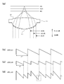
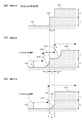
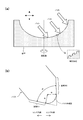
- FIG. 1A is a schematic diagram showing the configuration of the objective lens 10 of the present embodiment.
- FIG. 1A schematically shows a cross-sectional view when the objective lens 10 is cut by a plane parallel to the optical axis including the optical axis of the objective lens 10.
- a light source side lens surface 11 and a disk side lens surface 12 are formed on the light source side and the disk side of the objective lens 10, respectively.
- the curvature of the light source side lens surface 11 is larger than that of the disk side lens surface 12.
- the light source side lens surface 11 is formed with a diffractive structure concentrically around the optical axis.
- a diffractive structure includes a laser beam corresponding to a CD (hereinafter referred to as “CD light”), a laser beam corresponding to a DVD (hereinafter referred to as “DVD light”), and a laser beam corresponding to a BD (hereinafter referred to as “BD light”). Light)) can be properly converged on CD, DVD, and BD, respectively.
- the objective lens 10 is made of a resin material having excellent light transmittance, and is formed by injection molding or press molding.
- injection molding for example, molten resin is introduced from a gate into a space between a mold corresponding to the light source side lens surface 11 and a mold corresponding to the disk side lens surface 12, The mold is cooled. Thereafter, the two molds are separated and the objective lens 10 is taken out.
- press molding the deformable lens intermediate is pressed with two molds while being heated, and the pressed lens intermediate and the two molds are cooled. Thereafter, the two molds are separated from each other, and the objective lens 10 is taken out.
- the transferred surfaces corresponding to the lens surfaces of the objective lens 10 are formed on the two molds, respectively. Note that the transfer accuracy of the transfer surface with respect to the objective lens 10 is higher in the press molding than in the injection molding.
- the transfer surface of the mold corresponding to the light source side lens surface 11 is designed by overlapping a plurality of patterns.
- a pattern 1 having a pitch p1 as shown in FIG. 1 (b) and a pattern 2 having a pitch p2 as shown in FIG. 1 (c) are overlapped to form a pattern 3 shown in FIG. 1 (d).
- the pattern 3 may include a very narrow pattern such as a region surrounded by a broken line.
- FIGS. 2A to 2C are schematic views showing the configuration of a cutting tool used when forming a transferred surface of a mold corresponding to the light source side lens surface 11.
- the above-described mold formation is performed with a cutting tool.
- the tip of the cutting tool has a spherical shape, and the tool tip is moved from the left side to the right side of the mold to cut the surface of the mold. That is, when the ring-shaped transfer surface is formed on the mold, the cutting tool moves outward from the center of the mold. Such cutting is performed based on the pattern 3 in FIG.
- the cross-section of the tip of the cutting tool is circular as shown in FIGS. 2 (a) to 2 (c), it is not possible to cut the die as designed according to pattern 3 in FIG. 1 (d). Have difficulty. Further, if there is a pattern with a very narrow width, such as a region surrounded by a broken line in FIG. 1D, it becomes more difficult to perform cutting as designed. As described above, the mold portion generated by the circular shape of the cross-section of the tip of the cutting tool becomes a “phase mismatched portion” as shown by the oblique lines in FIGS.
- the objective lens 10 When the objective lens 10 is formed by a mold including a phase mismatch portion, if light is incident on a portion corresponding to the phase mismatch portion, the light becomes flare light and desired diffracted light cannot be obtained. That is, as shown in FIGS. 2A to 2C, when the diffractive structure of the objective lens 10 includes a curved surface different from the design, the optical performance of the objective lens 10 depends on the width of the phase mismatch portion. Will fall.
- FIGS. 2A and 2B show a case where the relationship between R and d is d ⁇ R ⁇ 2d and a case where R ⁇ d, respectively.
- FIG. 2C shows a case where the relationship between R and d is R ⁇ 2d.
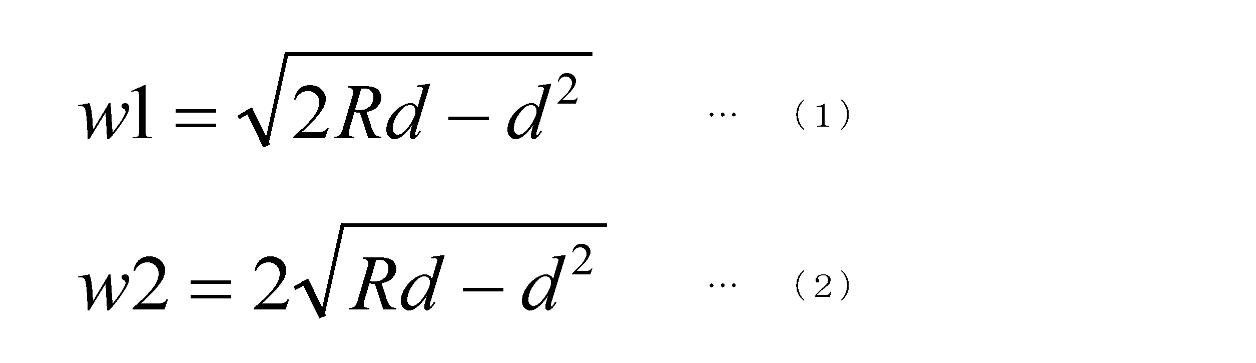
- the width w1 of the phase mismatch portion can be obtained by the calculation of the following equation (1).
- the width of the phase mismatch portion is equal to the radius R of the tip of the cutting tool.
- the width w2 of the phase mismatch portion can be obtained by the following equation (2).
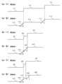
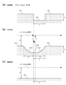
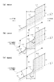
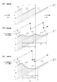
- FIGS. 3 (a-1), (b-1), and (c-1) are cross-sectional views showing an ideal shape composed of the lower, middle, and upper surfaces.
- surfaces I11 to I13, surfaces I01 to I03, and surfaces I21 to I23 are formed, respectively.
- the height positions of the surfaces I01, I11, and I21 are the same.
- the heights of the surfaces I02, I12, and I22 are the same, and the horizontal widths of the surfaces I12, I02, and I22 increase in this order.
- the height positions of the surfaces I03, I13, and I23 are the same.
- the left side of the drawing is the optical axis side of the objective lens formed by each mold, and the right side of the drawing is each mold. It is the outer peripheral side of the objective lens formed by.
- the positional relationship between the mold and the objective lens on the paper is the same for the other drawings.
- a curved surface portion (phase mismatched portion) corresponding to the curved surface of the bite is formed at the right end of the previous (left) surface so that the left end of each surface is aligned with the left end of the corresponding surface of the ideal shape.
- the above rule is applied.
- the surface C01 and the curved surface C02 are formed without forming the right end of the surface I01.
- the left end of the surface I02 is formed, and the right end of the surface I02 is not formed, and the middle step surface is formed.
- the width of the curved surface formed by the tip of the cutting tool and the width of the surface I02 are the same length, only the left end of the surface I02 is formed.
- a surface C04 is formed so as to form the left end of the surface I03.
- the above exception rule is applied.
- the surface C21 and the curved surface C22 are formed without forming the right end of the surface I21.
- the surface corresponding to the surface I22 is formed according to the exception rule. That is, the same surface C23 as the surface I22 is formed by forming the right end of the surface I22 and not forming the left end of the surface I23.
- a surface C25 corresponding to a portion other than the left end of the surface I23 is formed.
- the cutting shape of the mold is improved so that the width of the curved surface portion (phase mismatch portion) can be minimized.
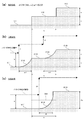
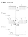
- FIG. 4 (a) shows an ideal of a die to be cut when R and d have the relationship shown in FIG. 2 (a) (d ⁇ R ⁇ 2d). It is a figure which shows a shape.
- Such an ideal shape is a partially enlarged view of the pattern at the time of design shown in FIG. 1 (d), and is the same as FIG. 3 (a-1).
- the width of the surface I12 is s, and the relationship between the width s of the surface I12 and the width w1 of the curved surface cut by the cutting tool tip (see FIG. 2A) is s ⁇ w1. Since s ⁇ w1, the above principle rule is applied when the comparative shape is cut from the ideal shape of FIG.
- FIG. 4 (b) is a diagram showing a comparative shape when the ideal shape of FIG. 4 (a) is cut according to the above principle rule, and is the same as FIG. 3 (a-2).
- a surface C13 similar to a part of the ideal-shaped surface I12 can be formed, but between the surfaces C11 and C13, A phase mismatch portion having curved surfaces C12 and C14 occurs between C13 and C15.
- the sum of the widths of the phase mismatched portions is 2w1.
- FIG. 4C is a diagram showing an implementation shape when the surface I12 is not formed regardless of the rules when cutting the ideal shape of FIG. 4A.
- Such an implementation shape has surfaces E11 and E13 and a curved surface E12.
- the ideal-shaped surface I12 is not formed, and a phase mismatch portion including the curved surface E12 is generated between the surface I11 and the surface I13.
- the width of the phase mismatch portion is the width s of the surface I12 that has not been formed.
- the ideal shape when the ideal shape is cut, a cutting shape having a smaller width of the phase mismatch portion is used among the comparative shape and the execution shape. Therefore, when the relationship between R and d is d ⁇ R ⁇ 2d and the relationship between s and w1 is s ⁇ w1, the ideal shape shown in FIG. Instead of the shape, the condition for using the implementation shape of FIG. 4C is s ⁇ 2w1. When such a condition is satisfied, the range of the curved surface E12 is included in the range of the surface I12 without forming the surface I12 as in the actual shape instead of the comparative shape. In this case, the width of the phase mismatch portion can be reduced, so that a decrease in optical performance of the formed objective lens is suppressed.
- the implementation shape in the case of s ⁇ R is shown, but in the case of s ⁇ R, the range of the surface I12 is included in the range of the curved surface E12. In this case, the width of the phase mismatch portion of the implementation shape is R. Therefore, when d ⁇ R ⁇ 2d and w1 ⁇ s ⁇ R, the condition for using the implementation shape instead of the comparison shape is R ⁇ 2w1.
- the curved surface E12 when the range of the curved surface E12 is included in the range of the surface I12 as shown in FIG. 4C, as shown in FIG. 5B, the right end of the surface I11 and the left end of the surface I13. Are connected by a curved surface E12 composed of two curved surfaces, and the connecting portion of the two curved surfaces is preferably set at the height position of the surface I12. In this way, the width of the phase mismatching portion is s as in FIG. 4C, but the curved surface E12 is closer to the ideal surface I12 than in FIG. The optical performance degradation is further suppressed.
- the curved surface E12 may be formed as a curved surface having a radius larger than R.
- the intermediate portion of the curved surface E12 may include a planar shape. This planar shape is preferably at the same height as the surface I12.
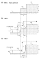
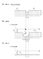
- FIG. 6 (a) shows an ideal of a die to be cut when R and d have the relationship shown in FIG. 2 (a) (d ⁇ R ⁇ 2d). It is a figure which shows a shape. Such an ideal shape is a partially enlarged view of the design pattern shown in FIG. 1D, and is the same as FIG. 3B-1 or FIG. 3C-1.
- the width of the surface I22 is s, and the relationship between the width s of the surface I22 and the width w1 of the curved surface cut by the cutting tool tip (see FIG. 2A) is s ⁇ w1. Since s ⁇ w1, the above exception rule is applied when the comparative shape is cut from the ideal shape of FIG.
- FIG. 6 (b) is a diagram showing a comparative shape when the ideal shape of FIG. 6 (a) is cut according to the exception rule, which is similar to FIG. 3 (b-2) or FIG. 3 (c-2). is there.
- the center of the cutting tool is moved along the broken line arrow according to the exception rule, a surface C23 similar to the ideal surface I22 can be formed, but curved surfaces C22 and C24 are provided on the left and right sides of the surface C23.
- a phase mismatch portion occurs.
- the sum of the widths of the phase mismatched portions is 2w1.
- FIG. 6C is a diagram showing an implementation shape when the surface I22 is not formed regardless of the rule when the ideal shape of FIG. 6A is cut.
- Such an implementation shape has surfaces E21, E23 and a curved surface E22.
- the ideal-shaped surface I22 is not formed, and a phase mismatch portion having a curved surface E22 is generated between the surfaces E21 and E23.
- the width of the phase mismatch portion is R.
- the ideal shape of FIG. instead of the shape, the condition for using the implementation shape of FIG. 6C is R ⁇ 2w1.
- the surface I22 is not included in the range of the curved surface E22 without forming the surface I22 as in the actual shape instead of the comparative shape. In this case, the width of the phase mismatch portion can be reduced, so that a decrease in optical performance of the formed objective lens is suppressed.
- the curved surface E22 intersects the position of the surface I22 as shown in FIG. 7B. It is desirable to do so. In this way, the width of the phase mismatching portion is the same R as in FIG. 6C, but the curved surface E22 is closer to the ideal surface I22 than in FIG. The optical performance degradation is further suppressed.
- FIG. 8A shows an ideal shape of a die to be cut when R and d have the relationship shown in FIG. 2B (R ⁇ d). It is.
- Such an ideal shape is a partially enlarged view of the pattern at the time of design shown in FIG. 1 (d), and is the same as FIG. 3 (a-1).
- the width of the surface I12 is s, and the relationship between the width s of the surface I12 and the radius R of the tip of the cutting tool is s ⁇ R. Since s ⁇ R, the above principle rule is applied when the comparative shape is cut from the ideal shape of FIG.
- FIG. 8 (b) is a diagram showing a comparative shape when the ideal shape of FIG. 8 (a) is cut according to the above principle rule, and is the same as FIG. 3 (a-2).
- a surface C13 similar to a part of the ideal-shaped surface I12 can be formed, but between the surfaces C11 and C13, A phase mismatch portion having curved surfaces C12 and C14 occurs between C13 and C15.
- the sum of the widths of the phase mismatched portions is 2R.
- FIG. 8C is a diagram showing an implementation shape when the surface I12 is not formed regardless of the principle rule when the ideal shape of FIG. 8A is cut.
- Such an implementation shape has surfaces E11 and E13 and a curved surface E12.
- the ideal-shaped surface I12 is not formed, and a phase mismatch portion including the curved surface E12 is generated between the surface I11 and the surface I13.
- the width of the phase mismatch portion is the width s of the surface I12 that has not been formed.
- the relationship between R and d is R ⁇ d and the relationship between s and R is s ⁇ R
- the condition for using the implementation shape of FIG. 8C is s ⁇ 2R.
- the range of the curved surface E12 is included in the range of the surface I12 without forming the surface I12 as in the actual shape instead of the comparative shape. In this case, the width of the phase mismatch portion can be reduced, so that a decrease in optical performance of the formed objective lens is suppressed.
- the range of the curved surface E12 is included in the range of the surface I12 as in the implementation shape of FIG. 8C, the right end of the surface I11 and the left end of the surface I13 are set as in FIG. It is desirable that the curved surface E12 is formed so as to be tied. Similarly to FIG. 5B, a part of the range of the surface I12 may be included in the range of the curved surface E12.
- FIG. 9A shows an ideal shape of a die to be cut when R and d have the relationship shown in FIG. 2B (R ⁇ d). It is.
- Such an ideal shape is a partially enlarged view of the design pattern shown in FIG. 1D, and is the same as FIG. 3B-1 or FIG. 3C-1.
- the width of the surface I22 is s, and the relationship between the width s of the surface I22 and the radius R of the tip of the cutting tool is s ⁇ R. Since s ⁇ R, the above exception rule is applied when the comparative shape is cut from the ideal shape of FIG.
- FIG. 9 (b) is a diagram showing a comparative shape when the ideal shape of FIG. 9 (a) is cut according to the exception rule, which is the same as FIG. 3 (b-2) or FIG. 3 (c-2). is there.
- This comparative shape has surfaces C21, C23, C25 and curved surfaces C22, C24.
- a surface C23 similar to the ideal-shaped surface I22 can be formed, but a phase having curved surfaces C22 and C24 on the left and right of the surface C23. Inconsistency occurs.
- the sum of the widths of the phase mismatched portions is 2R.
- FIG. 9C is a diagram showing an implementation shape when the surface I22 is not formed regardless of the rules when cutting the ideal shape of FIG. 9A.
- Such an implementation shape has surfaces E21, E23 and a curved surface E22.
- the ideal-shaped surface I22 is not formed, and a phase mismatch portion having a curved surface E22 is generated between the surfaces E21 and E23.
- the width of the phase mismatch portion is R.
- the right end of the curved surface E22 is an ideal shape surface. It is desirable to be able to adjust to the left end of I23. In this way, compared to the case where the left end of the curved surface E22 is aligned with the right end of the ideal-shaped surface I21, the curved surface E22 can be brought closer to the ideal-shaped surface I22. The decrease is further suppressed. Also in this case, as in FIG. 7B, a part of the range of the surface I22 may be included in the range of the curved surface E22.
- FIG. 10A shows an ideal shape of a die to be cut when R and d have the relationship shown in FIG. 2C (R ⁇ 2d). It is.
- Such an ideal shape is a partially enlarged view of the design pattern shown in FIG. 1D, and is the same as FIG. 3B-1 or FIG. 3C-1.
- the width of the surface I22 is s, and the relationship between the width s of the surface I22 and the width w1 of the curved surface cut by the cutting tool tip (see FIG. 2C) is s ⁇ w1. Since s ⁇ w1, the above exception rule is applied when the comparative shape is cut from the ideal shape of FIG.
- FIG. 10 (b) is a diagram showing a comparative shape when the ideal shape of FIG. 10 (a) is cut according to the exception rule, and is similar to FIG. 3 (b-2) or FIG. 3 (c-2). is there.
- a surface C23 similar to the ideal surface I22 can be formed, but curved surfaces C22 and C24 are provided on the left and right sides of the surface C23.
- a phase mismatch portion occurs.
- the sum of the widths of the phase mismatched portions is 2w1.
- FIG. 10 (c) is a diagram showing an implementation shape when the surface I22 is not formed regardless of the rules when cutting the ideal shape of FIG. 10 (a).
- Such an implementation shape has surfaces E21, E23 and a curved surface E22.
- the ideal-shaped surface I22 is not formed, and a phase mismatch portion having a curved surface E22 is generated between the surfaces E21 and E23.
- the width of the phase mismatch portion is w2.
- the right end of the curved surface E22 is an ideally shaped surface as shown in FIG. 10C. It is desirable to be able to adjust to the left end of I23. In this way, compared to the case where the left end of the curved surface E22 is aligned with the right end of the ideal-shaped surface I21, the curved surface E22 can be brought closer to the ideal-shaped surface I22. The decrease is further suppressed. Also in this case, as in FIG. 7B, a part of the range of the surface I22 may be included in the range of the curved surface E22.
- the comparative shape is substantially the same as in FIG. 4B, and the sum of the widths of the phase mismatched portions is 2w1.
- the implementation shape is substantially the same as in FIG. 4C, and the width of the phase mismatch portion is w2.
- the conditions for using the implementation shape are s ⁇ 2w1 if s> w2, and w2 ⁇ 2w1 if s ⁇ w2.
- s> w2 it is desirable to form a curved surface between the lower surface and the upper surface as in FIG. 5B.
- the curved surface has an ideal shape as in FIG. 7B. It is desirable to arrange it so as to be close to the middle surface.
- FIG. 11 (a) shows the ideal of the die to be cut when R and d have the relationship shown in FIGS. 2 (a) and 2 (c) (R> d). It is a figure which shows a shape.
- Such an ideal shape is a partially enlarged view of the pattern at the time of design shown in FIG. 1D, and has surfaces I31 to I33.
- the width of the surface I32 is s, and the relationship between the width s of the surface I32 and the width w1 of the curved surface cut by the tip of the cutting tool (see FIGS. 2A and 2C) is s ⁇ w1. Since s ⁇ w1, the above principle rule is applied when the comparative shape is cut from the ideal shape shown in FIG.
- FIG. 11B is a view showing a comparative shape when forming at least a part of the surface I32 when the ideal shape of FIG. 11A is cut according to the above-mentioned principle rule.
- a comparative shape has surfaces C31, C33, C35 and curved surfaces C32, C34.
- a surface C33 similar to a part of the ideal-shaped surface I32 can be formed, but curved surfaces C32, A phase mismatch portion with C34 results.
- the sum of the widths of the phase mismatched portions is 2w1.
- FIG. 11 (c) is a diagram showing an implementation shape when the surface I32 is not formed regardless of the rules when cutting the ideal shape of FIG. 11 (a).
- Such an implementation has only surface E31.
- the center of the cutting tool is moved along the broken line arrow, the ideal-shaped surface I32 is not formed, and a phase mismatch portion is generated in the range of the surface I32.
- the width of the phase mismatch portion is the width s of the surface I32 that is not formed.
- the resin bites the protruding portion having a small width in the vicinity of the surface C33, and the resin (objective lens 10) is made into the mold. It becomes difficult to peel from the mold.
- the resin (objective lens 10) can be smoothly peeled off from the mold, and a defect at the time of peeling at the protruding portion or the like. Can be suppressed.
- FIG. 12 (a) shows the ideal of the die to be cut when R and d have the relationship shown in FIGS. 2 (a) and 2 (c) (R> d). It is a figure which shows a shape.
- Such an ideal shape is a partially enlarged view of the pattern at the time of design shown in FIG. 1D, and has surfaces I41 to I43.
- the width of the surface I42 is s, and the relationship between the width s of the surface I42 and the width w1 of the curved surface cut by the cutting tool tip (see FIGS. 2A and 2C) is s ⁇ w1.
- FIG. 12 (b) is a diagram showing a comparative shape when cutting the ideal shape of FIG. 12 (a).
- the comparative shape is cut as follows regardless of the rule. First, the center of the cutting tool is moved in the right direction so as not to form the right end of the surface I41 but to form the left end of the surface I42. When the left end of the surface I42 is formed, the center of the cutting tool is moved upward by d and moved rightward to the position of the left end of the surface I43. Subsequently, the center of the cutting tool is moved downward by d so that the left end of the surface I43 is formed. After that, the center of the tool is moved to the right. Thereby, as shown in FIG.12 (b), a comparison shape will have the surfaces C41 and C44 and the curved surfaces C42 and C43. In this case, the sum of the widths of the phase mismatched portions is (w1 + s).
- FIG. 12 (c) is a diagram showing an implementation shape when the ideal shape of FIG. 12 (a) is cut.
- Such an implementation has only surface E41.
- the ideal-shaped surface I42 is not formed, and a phase mismatch portion is generated in the range of the surface I42.
- the width of the phase mismatch portion is s.
- the relationship between R and d is R> d and the relationship between s and w1 is s ⁇ w1
- the comparative shape shown in FIG. 12C is s ⁇ w1 + s. Since this condition is always satisfied, when R> d and s ⁇ w1, the width of the phase mismatch portion becomes smaller when the implementation shape is used instead of the comparison shape. In this case, the width of the phase mismatch portion can be reduced, so that a decrease in optical performance of the formed objective lens is suppressed.
- the implementation shape of FIG.12 (c) can peel the resin (objective lens 10) formed smoothly from a metal mold
- FIG. 13A shows the ideal shape of a die to be cut when R and d have the relationship shown in FIG. 2B (R ⁇ d). It is.
- Such an ideal shape is a partially enlarged view of the pattern at the time of design shown in FIG. 1D, and has surfaces I31 to I33.
- the width of the surface I32 is s
- the relationship between the width s of the surface I32 and the radius R of the tip of the cutting tool is s ⁇ R. Since s ⁇ R, the above principle rule is applied when the comparative shape is cut from the ideal shape of FIG.
- FIG. 13B is a diagram showing a comparative shape when forming at least a part of the surface I32 when the ideal shape of FIG. 13A is cut according to the principle rule.
- a comparative shape has surfaces C31, C33, C35 and curved surfaces C32, C34.
- a surface C33 similar to a part of the ideal-shaped surface I32 can be formed, but curved surfaces C32 and C34 are formed on the left and right sides of the surface C33.
- FIG. 13 (c) is a diagram showing an implementation shape when the surface I32 is not formed regardless of the rules when cutting the ideal shape of FIG. 13 (a).
- Such an implementation has only surface E31.
- the center of the cutting tool is moved along the broken line arrow, the ideal-shaped surface I32 is not formed, and a phase mismatch portion is generated in the range of the surface I32.
- the width of the phase mismatch portion is s.
- the implementation shape of FIG.13 (c) can peel the resin (objective lens 10) formed smoothly from a metal mold
- FIG. 14A shows an ideal shape of a die to be cut when R and d have the relationship shown in FIG. 2B (R ⁇ d). It is.
- Such an ideal shape is a partially enlarged view of the pattern at the time of design shown in FIG. 1D, and has surfaces I41 to I43.
- the width of the surface I42 is s, and the relationship between the width s of the surface I42 and the radius R of the tip of the cutting tool is s ⁇ R.
- FIG. 14 (b) is a diagram showing a comparative shape when cutting the ideal shape of FIG. 14 (a).
- the comparative shape in this case is cut in the same manner as in FIG. Thereby, as shown in FIG.14 (b), a comparison shape will have the surfaces C41 and C44 and the curved surfaces C42 and C43. In this case, the sum of the widths of the phase mismatched portions is (R + s).
- FIG. 14 (c) is a diagram showing an implementation shape in the case of cutting the ideal shape of FIG. 14 (a).
- Such an implementation has only surface E41.
- the ideal-shaped surface I42 is not formed, and a phase mismatch portion is generated in the range of the surface I42.
- the width of the phase mismatch portion is s.
- the relationship between R and d is R ⁇ d and the relationship between s and R is s ⁇ R
- the comparative shape in FIG. 14C is s ⁇ R + s. Since this condition is always satisfied, when R ⁇ d and s ⁇ R, the width of the phase mismatch portion becomes smaller when the implementation shape is used instead of the comparison shape. In this case, the width of the phase mismatch portion can be reduced, so that a decrease in optical performance of the formed objective lens is suppressed.
- the actual shape of FIG. 14C can peel the formed resin (objective lens 10) more smoothly from the mold, and at the time of peeling at the protruding portion. Defects and the like can be suppressed.
- FIG. 15 (a) shows the ideal of the die to be cut when R and d have the relationship shown in FIGS. 2 (a) and 2 (c) (R> d). It is a figure which shows a shape.
- This ideal shape is a partially enlarged view of the pattern at the time of design shown in FIG. 1 (d), and has surfaces I51 to I53.
- the width of the surface I52 is s, and the relationship between the width s of the surface I52 and the width w1 of the curved surface cut by the cutting tool tip (see FIGS. 2A and 2C) is s ⁇ w1. Since s ⁇ w1, the above principle rule is applied when the comparative shape is cut from the ideal shape shown in FIG.
- FIG. 15B is a diagram showing a comparative shape when forming at least a part of the surface I52 when the ideal shape of FIG. 15A is cut.
- the comparative shape has surfaces C51, C53, and C55, and curved surfaces C52 and C54.
- a surface C53 similar to a part of the ideal-shaped surface I52 can be formed, but curved surfaces C52, A phase mismatch portion with C54 results.
- the sum of the widths of the phase mismatched portions is 2w1.
- FIG. 15C is a diagram showing an implementation shape when the surface I52 is not formed regardless of the rules when cutting the ideal shape of FIG. 15A.
- Such an implementation has only surface E51.
- the center of the cutting tool is moved along the broken line arrow, the ideal-shaped surface I52 is not formed, and a phase mismatch portion is generated in the range of the surface I52.
- the width of the phase mismatch portion is s.
- the relationship between R and d is R> d and the relationship between s and w1 is s ⁇ w1
- the comparative shape shown in FIG. 15C is s ⁇ 2w1.
- the surface I52 is not formed as in the actual shape instead of the comparative shape.
- the width of the phase mismatch portion can be reduced, so that a decrease in optical performance of the formed objective lens is suppressed.
- a dent having a small width does not occur in the mold, and thus the resin does not smoothly flow into the dent. Can be suppressed.
- FIG. 16A shows the ideal of the die to be cut when R and d have the relationship shown in FIGS. 2A and 2C (R> d). It is a figure which shows a shape. This ideal shape is a partially enlarged view of the pattern at the time of design shown in FIG. 1 (d), and has surfaces I61 to I63.
- the width of the surface I62 is s, and the relationship between the width s of the surface I62 and the width w1 (see FIGS. 2A and 2C) of the curved surface cut by the cutting tool tip is s ⁇ w1.
- FIG. 16 (b) is a diagram showing a comparative shape when cutting the ideal shape of FIG. 16 (a).
- the comparative shape is cut as follows regardless of the rule. First, the center of the cutting tool is moved to the right, and the center of the cutting tool is moved downward by d so as to form the position of the left end of the surface I62. When the left end of the surface I62 is formed, the center of the cutting tool is moved upward by d and then moved to the right. Thereby, as shown in FIG.16 (b), a comparison shape will have the surfaces C61 and C63 and the curved surface C62. In this case, the sum of the widths of the phase mismatched portions is 2w1.
- FIG. 16 (c) is a diagram showing an implementation shape when cutting the ideal shape of FIG. 16 (a).
- Such an implementation has only surface E61.
- the ideal-shaped surface I62 is not formed, and a phase mismatch portion is generated in the range of the surface I62.
- the width of the phase mismatch portion is s.
- the condition for using the embodiment shown in FIG. 16C is s ⁇ 2w1. Since this condition is always satisfied, when R> d and s ⁇ w1, the width of the phase mismatch portion becomes smaller when the implementation shape is used instead of the comparison shape. In this case, the width of the phase mismatch portion can be reduced, so that a decrease in optical performance of the formed objective lens is suppressed.
- a recess having a small width does not occur in the mold, and thus the resin does not smoothly flow into the recess. Can be suppressed.
- FIG. 17A shows an ideal shape of a die to be cut when R and d have the relationship shown in FIG. 2B (R ⁇ d). It is.
- This ideal shape is a partially enlarged view of the pattern at the time of design shown in FIG. 1 (d), and has surfaces I51 to I53.
- the width of the surface I52 is s, and the relationship between the width s of the surface I52 and the radius R of the cutting tool tip is s ⁇ R. Since s ⁇ R, the above principle rule is applied when the comparative shape is cut from the ideal shape of FIG.
- FIG. 17B is a diagram showing a comparative shape when forming at least a part of the surface I52 when the ideal shape of FIG. 17A is cut according to the principle rule.
- a comparative shape has surfaces C51, C53, C55 and curved surfaces C52, C54.
- a surface C53 similar to a part of the ideal-shaped surface I52 can be formed, but curved surfaces C52, A phase mismatch portion with C54 results.
- the sum of the widths of the phase mismatched portions is 2R.
- FIG. 17 (c) is a diagram showing an implementation shape when the surface I52 is not formed regardless of the rules when cutting the ideal shape of FIG. 17 (a).
- Such an implementation has only surface E51.
- the center of the cutting tool is moved along the broken line arrow, the ideal-shaped surface I52 is not formed, and a phase mismatch portion is generated in the range of the surface I52.
- the width of the phase mismatch portion is s.
- the relationship between R and d is R ⁇ d and the relationship between s and R is s ⁇ R
- the condition for using the embodiment shown in FIG. 17C is s ⁇ 2R.
- the surface I52 is not formed as in the actual shape instead of the comparative shape.
- the width of the phase mismatch portion can be reduced, so that a decrease in optical performance of the formed objective lens is suppressed.
- a depression with a small width does not occur in the mold, and thus the resin does not flow smoothly into the depression. Can be suppressed.
- FIG. 18A shows an ideal shape of a die to be cut when R and d have the relationship shown in FIG. 2B (R ⁇ d). It is.
- This ideal shape is a partially enlarged view of the pattern at the time of design shown in FIG. 1 (d), and has surfaces I61 to I63.
- the width of the surface I62 is s, and the relationship between the width s of the surface I62 and the radius R of the tip of the cutting tool is s ⁇ R.
- FIG. 18 (b) is a diagram showing a comparative shape when cutting the ideal shape of FIG. 18 (a).
- the comparative shape is formed in the same manner as in the case of FIG.
- a comparison shape will have the surfaces C61 and C63 and the curved surface C62.
- the sum of the widths of the phase mismatched portions is 2R.
- FIG. 18 (c) is a diagram showing an implementation shape in the case of cutting the ideal shape of FIG. 18 (a).
- Such an implementation has only surface E61.
- the ideal-shaped surface I62 is not formed, and a phase mismatch portion is generated in the range of the surface I62.
- the width of the phase mismatch portion is s.
- the condition for using the embodiment shown in FIG. 18C is s ⁇ 2R. Since this condition is always satisfied, when R ⁇ R and s ⁇ R, the width of the phase mismatch portion becomes smaller when the implementation shape is used instead of the comparison shape. In this case, the width of the phase mismatch portion can be reduced, so that a decrease in optical performance of the formed objective lens is suppressed.
- a depression with a small width does not occur in the mold, and thus the resin does not smoothly flow into the depression. Can be suppressed.
- FIG. 19A is a diagram showing an ideal shape of a die to be cut when R and d have the relationship shown in FIG. 2A (d ⁇ R ⁇ 2d), as in FIG. 6A. .
- the relationship between s and w1 is s ⁇ w1.
- FIG. 19 (b) is a diagram showing a comparative shape in this case, as in FIG. 6 (b).
- FIG. 19 (c) is a diagram showing an implementation shape when the surface I22 is not formed when the ideal shape of FIG. 19 (a) is cut.
- Such an implementation shape has surfaces E21 and E23 and curved surfaces E22a and E22b.
- the ideal-shaped surface I22 is not formed, and a phase mismatch portion having curved surfaces E22a and E22b is generated between the surfaces E21 and E23.
- the curved surface E22a has a shape corresponding to the curved surface of the cutting tool when the center of the cutting tool is at O1
- the curved surface E22b has a shape corresponding to the curved surface of the cutting tool when the center of the cutting tool is at O2.
- the curved surface E22a and the curved surface E22b are in contact with each other at the boundary B.
- the boundary B is included in the range of the ideal-shaped surface I22 and is positioned at the same height as the surface I22. In this case, the width of the sum of the phase mismatch portions is w3.
- the condition for using the implementation shape of FIG. 19C is w3 ⁇ 2w1.
- the surface I22 is not included in the range of the curved surfaces E22a and E22b without forming the surface I22 as in the actual shape instead of the comparative shape. In this case, the width of the phase mismatch portion can be reduced, so that a decrease in optical performance of the formed objective lens is suppressed.
- the boundary B is configured to be a point in the side view as illustrated in FIG. 19C
- the boundary B may be configured to include a part of the ideal-shaped surface I22.
- FIG. 19C shows the case where the relationship between R and d is d ⁇ R ⁇ 2d.
- the present invention is not limited to this, and even when R ⁇ d and R ⁇ 2d, FIG. 19 (c)
- An implementation shape may be formed in the same manner as in the above. In these cases as well, curved surfaces E22a and E22b are formed on the left and right sides of the boundary B, as in FIG.
- the portions of the curved surfaces E22a and E22b in which the gap in the height direction between the ideal-shaped surface I22 and the curved surfaces E22a and E22b is 1/10 or less of the wavelength of light used for the molded objective lens are the surfaces. It functions as a surface equivalent to I22, and this portion is not a phase mismatch portion. Accordingly, in the embodiment shown in FIG. 19C, a surface equivalent to the surface I22 can be formed in the vicinity of the boundary B, and the optical characteristics of the objective lens can be improved.
- optical pickup device ⁇ Optical pickup device>
- an embodiment using the objective lens formed as described above will be described.
- the present invention is applied to an optical pickup apparatus that can handle BD, DVD, and CD.
- FIG. 20 is a diagram showing an optical system of the optical pickup device according to the present embodiment.
- the optical system of the optical pickup device includes semiconductor lasers 101a to 101c, diverging lenses 102a and 102b, polarization beam splitters 103a to 103c, a collimator lens 104, a lens actuator 105, a rising mirror 106, and a quarter wavelength.
- a plate 107, an aperture 108, an objective lens 109, a holder 110, an objective lens actuator 111, an anamorphic lens 112, and a photodetector 113 are provided.
- the objective lens 109 is an objective lens formed as described above.
- the semiconductor lasers 101a to 101c emit laser light for BD (wavelength: 405 nm), laser light for DVD (wavelength: 660 nm), and laser light for CD (wavelength: 785 nm), respectively.
- BD laser beam for BD
- DVD laser beam for CD
- CD CD light
- the semiconductor lasers 101a to 101c are alternatively used depending on the disk on which recording / reproduction is performed.
- the diverging lenses 102a and 102b are arranged such that the DVD light and the CD light emitted from the semiconductor lasers 101b and 101c converge on the photodetector 113 in the same manner as the BD light emitted from the semiconductor laser 101a. Adjust the light spread angle.
- Each of the polarization beam splitters 103a to 103c substantially totally reflects BD light, DVD light, and CD light (S-polarized light), and substantially totally transmits laser light (P-polarized light) incident from the collimator lens 104 side.
- the collimator lens 104 changes the divergence angle of the BD light, DVD light, and CD light incident from the polarization beam splitter 103c side. For example, when BD light or DVD light is used, the collimator lens 104 is positioned at a position where these laser lights are incident on the objective lens 109 in an infinite system (parallel light). When CD laser light is used, the collimator lens 104 is positioned at a position where the CD laser light is incident on the objective lens 109 in a finite system (diffused light).
- the lens actuator 105 changes the position of the collimator lens 104 for each wavelength as described above, and displaces the collimator lens 104 in the optical axis direction according to the servo signal. Thereby, the aberration which arises in the laser beam of each wavelength is corrected.
- the rising mirror 106 reflects the laser light of each wavelength incident from the collimator lens 104 side in the direction toward the objective lens 109.
- the quarter-wave plate 107 converts the laser light of each wavelength toward the disk into circularly polarized light, and converts the reflected light from the disk into linearly polarized light orthogonal to the polarization direction when traveling toward the disk. Thereby, the laser light of each wavelength reflected by the disk is transmitted through the polarization beam splitters 103a to 103c.
- the aperture 108 adjusts the beam shape of the laser light of each wavelength to a circular shape so that the effective diameter of the laser light of each wavelength with respect to the objective lens 109 is appropriate.
- the aperture 108 is formed with a wavelength-selective reflective film so as to limit the opening of only the laser light of each wavelength.
- the objective lens 109 has a blazed diffraction structure (hologram) formed on the incident surface (the surface on the aperture 108 side), and each laser beam of each wavelength is appropriately applied to the target recording layer in the disk corresponding to each wavelength. It is designed to converge.
- hologram blazed diffraction structure
- the holder 110 integrally holds the quarter-wave plate 107, the aperture 108, and the objective lens 109.
- the objective lens actuator 111 is constituted by a conventionally known electromagnetic drive circuit, and a coil portion such as a focus coil is mounted on the holder 110 in the circuit.
- the anamorphic lens 112 introduces astigmatism into the laser light of each wavelength incident from the polarization beam splitter 103a side.
- the detection signal output from the sensor of the photodetector 113 is arithmetically processed according to the above formulas (1) and (2) by a signal arithmetic circuit (not shown) at the subsequent stage of the photodetector 113, and the focus error signal and the push signal are pushed. A pull signal is generated. Further, the signal arithmetic circuit adds the detection signals output from these eight sensors to generate a reproduction RF signal.
- the widths of the ideal-shaped surfaces I12, I22, I32, I42, I52, and I62 are smaller than the predetermined width as described above, these ideal-shaped surfaces are omitted. That is, when the ideal shape surface is omitted, the ideal shape surface is omitted when the width of the phase mismatch portion can be suppressed rather than leaving the ideal shape surface as in the comparative shape. In this way, when the transfer surface of the mold corresponding to the light source side lens surface 11 of the objective lens 10 is formed, the width of the phase mismatch portion is larger than when the mold is formed according to only the comparative shape. Becomes smaller. Thereby, the fall of the optical performance of the objective lens 10 formed can be suppressed.
- the surface shape (curved surface E12) connecting the surface I11 and the surface I13 is a shape corresponding to the curved surface of the bite as shown in FIGS. 4 (c) and 8 (c).
- the surface shape (curved surface E22) connecting the surface I21 and the surface I23 is a curved surface of a bite as shown in FIGS. 6 (c), 7 (b), 9 (c), and 10 (c). It has a corresponding shape.
- the width of the surface shape connecting the upper and lower surfaces is minimum when the surface shape is a shape corresponding to the curved surface of the bite, and becomes larger as the shape becomes gentler.
- the width of the phase mismatching portion can be set to the minimum, and the optical objective lens 10 to be formed is optically Deterioration of characteristics can be suppressed.
- the surface shape (curved surface E12) connecting the surface I11 and the surface I13 intersects the ideally shaped surface I12 as shown in FIGS. 4 (c) and 5 (b). Further, the surface shape (curved surfaces E22, E22a, E22b) connecting the surface I21 and the surface I23 is changed to an ideal-shaped surface I22 as shown in FIGS. 7B, 10C, and 19C. Crosses. As a result, the surface shape connecting the surface I11 and the surface I13 and the surface shape connecting the surface I21 and the surface I23 can be brought close to the ideally shaped surface I12 and the surface I22, respectively.
- the left end of the surface E22b is considerably close to the ideally shaped surface I22. Therefore, this portion easily functions as a surface equivalent to the ideal surface. For this reason, the deterioration of the optical characteristics of the objective lens 10 to be formed can be further suppressed.
- the curved surface E22 is the center of the objective lens 10 (the center of the mold) as much as possible within the range of the surface I22. It is desirable to be formed at a position approaching.
- the diameter of the annular zone formed by the curved surface E22 can be reduced as compared with the case where the curved surface E22 is formed at a position away from the center of the objective lens 10 (center of the mold). And the area occupied by the curved surface E22 can be suppressed.
- the curved surface E22 is formed at a position closest to the center of the objective lens 10 (center of the mold) in the range of the surface I22.
- the optical pickup device when configured as described above, a decrease in the optical performance of the objective lens 109 is suppressed as in the embodiment of the objective lens. As a result, the BD light, DVD light, and CD light emitted from the semiconductor lasers 101a to 101c can be accurately converged on the BD, DVD, and CD, respectively.
- the object of application of the lens manufacturing method according to the present invention is the objective lenses 10 and 109, but the lens manufacturing method according to the present invention. Is applicable to lenses other than the objective lenses 10 and 109. According to the lens manufacturing method of the present invention, it is possible to suppress a decrease in optical characteristics even in lenses other than the objective lens.
- the objective lenses 10 and 109 of the above embodiment are configured to converge the three laser beams (BD light, DVD light, CD light) on the three disks (BD, DVD, CD), respectively.
- the present invention is not limited to this, and a configuration may be adopted in which laser beams of a plurality of wavelength bands are converged on a disk corresponding to each laser beam. Further, a single laser beam may be configured to converge on a corresponding disk.
- the present invention does not correspond to a specific laser beam and disk, but is effective when forming a mold having a complicated structure as shown in FIG.
- the cross section of the tip of the cutting tool is circular.
- the shape is not limited to this, and may be elliptical.
- the mold when forming a mold, the mold is first rotated around the rotation axis. Then, the tool shown in FIG. 21B is driven up, down, left, and right in a state where the cutting tool is tilted by a predetermined inclination angle, thereby forming a mold.
- the shape of the inner surface of the mold is a curved surface corresponding to the lens surface of the objective lens
- the surface defining the ideal shape of the mold is, for example, a partially enlarged view shown in FIG. Furthermore, it will incline from a horizontal surface with the inclination of the inner surface of a metal mold
- the tip of the cutting tool is a spherical surface having a radius R, and is formed at the opening angle of the cutting tool tip (the angle of the cutting edge), that is, at both ends of the cutting tool tip.
- the opening angle of the end portions B1 and B2 is a predetermined angle ⁇ .
- FIG. 22 (a) is a diagram showing an ideal shape of a die to be cut.
- Such an ideal shape has surfaces I31 to I33.
- the surfaces I31 to I33 are inclined by ⁇ with respect to the horizontal direction.
- the width of the surface I32 is s, and the surface I32 protrudes from the surfaces I31 and I33 by a width d in the vertical direction.
- the left direction and the right direction are the inner direction and the outer direction of the objective lens to be formed, respectively.
- FIG. 22 (b) is a diagram showing the shape (comparative shape) of the mold when the surface is formed while leaving the surface I32 when the mold is cut according to the ideal shape of FIG. 22 (a).
- surfaces C31, C33, C35 and curved surfaces C32, C34 are formed.
- the center of the cutting tool tip is moved along the broken line arrow.
- a surface C33 similar to the ideal-shaped surface I32 can be formed, but the phase mismatched portions by the curved surfaces C32 and C34 are formed on the left and right sides of the surface C33. Occurs on the transfer surface.
- the width w4 of the curved surface C32 and the width w5 of the curved surface C34 can be obtained by the following expressions (3) and (4), respectively. Therefore, the sum of the widths of the phase mismatched portions in this case is w4 + w5.
- FIG. 22 (c) is a diagram showing a mold shape (implemented shape) when a surface is formed without forming the surface I32 when the ideal shape of FIG. 22 (a) is cut.
- a mold shape implemented shape
- only the surface E31 is formed.
- the center of the cutting tool tip is moved along the broken line arrow.
- the ideal-shaped surface I32 is not formed, and a phase mismatch portion due to the lack of the surface I32 occurs on the transfer surface of the objective lens.
- the width of the phase mismatch portion is the width s corresponding to the surface I32.
- the condition for using the actual shape of FIG. 22C instead of the comparative shape of FIG. 22B is s ⁇ (w4 + w5).
- the surface I32 is not formed as in the actual shape instead of the comparative shape.
- the width of the phase mismatch portion can be reduced, so that a decrease in optical performance of the formed objective lens is suppressed.
- FIG. 23 (a) is a diagram showing an ideal shape of a die to be cut.
- Such an ideal shape has surfaces I51 to I53.
- the planes I51 to I53 are inclined by ⁇ with respect to the horizontal direction.
- the width of the surface I52 is s, and the surface I52 is recessed by a width d in the vertical direction with respect to the surfaces I51 and I53.
- FIG. 23 (b) is a diagram showing the shape (comparative shape) of the mold when forming the surface while leaving the surface I52 when cutting the mold according to the ideal shape of FIG. 23 (a).
- surfaces C51, C53, and C55 and curved surfaces C52 and C54 are formed.
- the center of the cutting tool tip is moved along the broken line arrow.
- a surface C53 similar to the ideal-shaped surface I52 can be formed, but the phase mismatched portions by the curved surfaces C52 and C54 are formed on the left and right sides of the surface C53. Occurs on the transfer surface.
- the width w5 of the curved surface C52 and the width w4 of the curved surface C54 can be obtained by the calculations of the above equations (4) and (3), respectively. In this case, the sum of the widths of the phase mismatched portions is w4 + w5.
- FIG. 23 (c) is a diagram showing the mold shape (implemented shape) when the surface is formed without forming the surface I52 when the ideal shape of FIG. 23 (a) is cut.
- the center of the cutting tool tip is moved along the broken line arrow.
- the ideal-shaped surface I52 is not formed, and a phase mismatch portion due to the lack of the surface I52 is generated on the transfer surface of the objective lens.
- the phase mismatched portion has a width s corresponding to the surface I52.
- the condition for using the actual shape of FIG. 23C instead of the comparative shape of FIG. 23B is s ⁇ (w4 + w5).
- the surface I52 is not formed as in the actual shape instead of the comparative shape.
- the width of the phase mismatch portion can be reduced, so that a decrease in optical performance of the formed objective lens is suppressed.
- FIG. 24 (a) is a diagram showing an ideal shape of a die to be cut.
- Such an ideal shape has surfaces I11 to I13.
- the planes I11 to I13 are inclined by ⁇ with respect to the horizontal direction.
- the width of the surface I12 is s, and the surface I12 is between the surface I11 and the surface I13.
- the distance between the surfaces I11 and I12 in the vertical direction and the distance between the surfaces I12 and I13 in the vertical direction are each a width d.
- FIG. 24B shows the shape of the mold when the surface is formed while leaving the left end of the surface I12 and the left end of the surface I13 when cutting the mold according to the ideal shape of FIG. 24A (comparative shape).
- FIG. in such a comparative shape surfaces C11, C13, C15 and curved surfaces C12, C14 are formed.
- the center of the cutting tool tip is moved along the broken line arrow.
- a surface C13 similar to the ideal-shaped surface I12 can be formed, but phase mismatched portions by the curved surfaces C12 and C14 are formed on the left and right sides of the surface C13. Occurs on the transfer surface.
- the widths w4 of the curved surfaces C12 and C14 can be obtained by the calculation of the above formula (3). In this case, the sum of the widths of the phase mismatched portions is 2w4.
- FIG. 24 (c) is a diagram showing the shape (implemented shape) of the mold when forming the surface without forming the surface I12 when cutting the ideal shape of FIG. 24 (a).
- surfaces E11 and E13 and a curved surface E12 are formed.
- the center of the cutting tool tip is moved along the broken line arrow.
- the width of the phase mismatching portion is the width s corresponding to the surface I12.
- the condition for using the actual shape of FIG. 24C instead of the comparative shape of FIG. 24B is s ⁇ 2w4.
- the surface I12 is not formed as in the actual shape instead of the comparative shape.
- the width of the phase mismatch portion can be reduced, so that a decrease in optical performance of the formed objective lens is suppressed.
- FIG. 25 (a) is a diagram showing an ideal shape of a die to be cut.
- Such an ideal shape has surfaces I11 to I13.
- the planes I11 to I13 are inclined by ⁇ with respect to the horizontal direction.
- the width of the surface I12 is s, and the surface I12 is between the surface I11 and the surface I13.
- the distance between the surfaces I11 and I12 in the vertical direction and the distance between the surfaces I12 and I13 in the vertical direction are each a width d.
- FIG. 25 (b) shows the shape of the mold in the case where the surface is formed while leaving the right end of the surface I12 and the right end of the surface I13 when cutting the mold according to the ideal shape of FIG. 25 (a) (comparative shape).
- FIG. in such a comparative shape surfaces C11, C13, C15 and curved surfaces C12, C14 are formed.
- the center of the cutting tool tip is moved along the broken line arrow.
- a surface C13 similar to the ideal-shaped surface I12 can be formed, but phase mismatched portions by the curved surfaces C12 and C14 are formed on the left and right sides of the surface C13. Occurs on the transfer surface.
- the widths w5 of the curved surfaces C12 and C14 can be obtained by the calculation of the above formula (4). In this case, the sum of the widths of the phase mismatched portions is 2w5.
- FIG. 25 (c) is a diagram showing the shape (implemented shape) of the mold when forming the surface without forming the surface I12 when cutting the ideal shape of FIG. 25 (a).
- surfaces E11 and E13 and curved surfaces E12 and E14 are formed.
- the center of the cutting tool tip is moved along the broken line arrow.
- the cutting tool tip is moved in this way, the ideally shaped surface I12 is not formed, and a phase mismatch portion due to the lack of the surface I12 occurs on the transfer surface of the objective lens.
- the sum w6 of the width of the curved surface E12 and the width of the curved surface E14 can be obtained by the calculation of the following equation (5), assuming that the end B1 of the cutting tool tip is inclined by ⁇ with respect to the horizontal direction. .
- the condition for using the actual shape of FIG. 25C instead of the comparative shape of FIG. 25B is w6 ⁇ 2w5.
- the surface I12 is not formed as in the actual shape instead of the comparative shape.
- the width of the phase mismatch portion can be reduced, so that a decrease in optical performance of the formed objective lens is suppressed.
- the curved surfaces E12 and E14 are desirably formed on the left side so as to be closest to the center of the objective lens 10 (center of the mold) in the range of the surface I12.
- Objective lens (lens) 11 Light source side lens surface (transmission surface) I01, I11, I21 ... plane (ideal plane, first ideal plane) I02, I12, I22 ... plane (ideal plane, ideal plane to be omitted) I03, I13, I23 ... plane (ideal plane, second ideal plane) E11, E13, E21, E23 ... surface (transfer surface, surface shape) E12, E14, E22, E22a, E22b ... Curved surface (surface, transferred surface, surface shape) E31, E41, E51, E61 ... surface (transfer target surface) I31 to I33, I41 to I43, I51 to I53, I61 to I63 ... plane (ideal plane)
Landscapes
- Physics & Mathematics (AREA)
- Optics & Photonics (AREA)
- General Physics & Mathematics (AREA)
- Optical Head (AREA)
Abstract
【課題】光学的な性能の低下を抑制可能なレンズの製造方法、その製造方法によって製造された対物レンズ、および、当該対物レンズを搭載した光ピックアップ装置を提供する。 【解決手段】 レンズを形成するための金型は、曲面を有する切削用のバイトにより形成される。この金型は、回折構造をレンズの表面に形成するための複数段の被転写面を有している。複数段の被転写面は、所定の回折作用をレンズに付与するために設計された複数段の理想面のうち所定の幅よりも小さい面I22を省略するよう構成されている。これにより、理想形状の面I22近傍において形成された曲面E22を有する位相不整合部分の幅が小さくなり、金型によって形成されるレンズの光学的な特性の低下が抑制される。
Description
本発明は、レンズの製造方法、対物レンズ、および、対物レンズを搭載した光ピックアップ装置に関するものである。
1つの対物レンズによって、複数の波長帯のレーザ光を各レーザ光に対応するディスク上に収束させる光ピックアップ装置が知られている。かかる対物レンズには、たとえば、複数の回折パターンが重畳された回折構造が形成される(特許文献1参照)。
上記対物レンズの回折構造は、金型に樹脂を流入させることにより形成される。また、かかる金型は、曲面形状を有する切削用のバイトにより形成される。しかしながら、バイトにより形成された金型は、設計時の理想形状とは異なり、丸みを帯びた形状を有することになる。このため、成型された対物レンズも、設計時の理想形状とは異なったものとなる。対物レンズの理想形状と異なる部分に光が入射すると、かかる光はフレア光となるため、対物レンズの光学的な性能が低下する惧れがある。
本発明は、かかる課題を解消するために為されたものであり、光学的な性能の低下を抑制可能なレンズの製造方法、その製造方法によって製造された対物レンズ、および、当該対物レンズを搭載した光ピックアップ装置を提供することを目的とする。
本発明の第1の態様は、曲面を有する切削用のバイトにより形成された金型によってレンズを形成するレンズの製造方法に関する。この態様において、前記金型は、回折構造を前記レンズの表面に形成するための複数段の被転写面を有する。前記複数段の被転写面は、所定の回折作用を前記レンズに付与するために設計された複数段の理想面のうち所定の幅よりも小さい理想面を省略するよう構成されている。
本態様に係るレンズの製造方法によれば、金型に形成される被転写面は、所定の幅よりも小さい理想面を省略するよう構成されている。ここで、バイトにより形成される金型の形状は曲面を有するため、金型に所定の幅よりも小さい被転写面を形成しようとすると、却って、理想形状と異なる部分の範囲が広がってしまう。このため、この金型によって形成されるレンズの光学的な特性が低下する結果となる。本態様に係るレンズの製造方法によれば、所定の幅よりも小さい理想面を省略して被転写面を形成することで、理想形状と異なる部分の範囲が抑制される。よって、当該金型によって形成されるレンズの光学的な特性の低下を抑制することができる。
本態様に係るレンズの製造方法において、前記省略対象の理想面が、当該省略対象の理想面よりも低い第1理想面と、当該省略対象の理想面よりも高い第2理想面との間にあるとき、前記第1理想面と前記第2理想面とを繋ぐ面形状を設けることにより、前記省略対象の理想面が省略されているよう構成され得る。こうすると、第1理想面と第2理想面とを繋ぐ面形状が、省略された理想面に近づけられるため、形成されるレンズの光学的な特性の低下が抑制される。
この場合、前記第1理想面と前記第2理想面とを繋ぐ前記面形状は、前記バイトの曲面に対応する形状となっているよう構成され得る。こうすると、理想面と異なるように形成された金型部分の幅を最小に設定することができるため、形成されるレンズの光学的な特性の低下が抑制される。
また、この場合、前記第1理想面と前記第2理想面とを繋ぐ前記面形状の少なくとも一部が、前記省略対象の理想面に対応する仮想面に交わるよう構成され得る。こうすると、理想面に置き換えられた金型部分の面形状を理想面に近づけることができるため、形成されるレンズの光学的な特性の低下が抑制される。
また、本態様に係るレンズの製造方法において、前記第1理想面と前記第2理想面とを繋ぐ前記面形状は、少なくとも2つの曲面部分を有し、2つの前記曲面部分の接続部が、前記省略対象の理想面に対応する高さの位置に位置づけられるよう構成され得る。こうすると、接続部付近が理想面に近づけられるため、形成されるレンズの光学的な特性の低下が抑制される。
また、本態様に係るレンズの製造方法において、前記理想面を残すように金型を切削する場合に前記レンズに生じる位相不整合部分の幅が、前記理想面を省略するように金型を切削する場合に前記レンズに生じる位相不整合部分の幅よりも大きくなる場合に、当該理想面を省略するよう、前記複数段の被転写面が構成され得る。
本発明の第2の態様は、対物レンズに関する。この態様に係る対物レンズは、光の透過面に複数段の面からなる回折構造を有する。ここで、前記複数段の面は、所定の回折作用を付与するために設計された複数段の理想面のうち所定の幅よりも小さい理想面を省略するよう構成されている。
本態様に係る対物レンズによれば、上記第1の態様と同様、レンズの光学的な特性の低下が抑制され得る。
本態様に係る対物レンズにおいて、前記理想面を残す場合に生じる位相不整合部分の幅が、前記理想面を省略する場合に生じる位相不整合部分の幅よりも大きくなる場合に、当該理想面を省略するよう、前記複数段の面が構成され得る。
本発明の第3の態様は、光ピックアップ装置に関する。この態様に係る光ピックアップ装置には、上記第2の態様に係る対物レンズが搭載されている。
本態様に係る光ピックアップ装置によれば、対物レンズの光学的な特性の低下が抑制されるため、光ピックアップ装置における特性を高めることができる。
本態様に係る光ピックアップ装置において、前記理想面を残す場合に前記対物レンズに生じる位相不整合部分の幅が、前記理想面を省略する場合に前記対物レンズに生じる位相不整合部分の幅よりも大きくなる場合に、当該理想面を省略するよう、前記複数段の面が構成され得る。
以上のとおり、本発明によれば、光学的な性能の低下を抑制可能なレンズの製造方法、その製造方法によって製造された対物レンズ、および、当該対物レンズを搭載した光ピックアップ装置を提供することができる。
本発明の効果ないし意義は、以下に示す実施の形態の説明により更に明らかとなろう。ただし、以下の実施の形態は、あくまでも、本発明を実施化する際の一つの例示であって、本発明は、以下の実施の形態に記載されたものに何ら制限されるものではない。
ただし、図面はもっぱら説明のためのものであって、この発明の範囲を限定するものではない。
以下、本発明の実施の形態について、図面を参照して説明する。
以下に示す実施の形態において、対物レンズ10、109は、本発明の「レンズ」に相当する。光源側レンズ面11は、本発明の「透過面」に相当する。面I01、I11、I21は、本発明の「理想面」、「第1理想面」に相当する。面I02、I12、I22は、本発明の「理想面」、「省略対象の理想面」に相当する。面I03、I13、I23は、本発明の「理想面」、「第2理想面」に相当する。面E11、E13、E21、E23は、本発明の「被転写面」、「面形状」に相当する。曲面E12、E14、E22、E22a、E22bは、本発明の「面」、「被転写面」、「面形状」に相当する。面E31、E41、E51、E61は、本発明の「被転写面」に相当する。面I31~I33、I41~I43、I51~I53、I61~I63は、本発明の「理想面」に相当する。本発明と本実施の形態との対応の記載はあくまで一例であって、本発明を本実施の形態に限定するものではない。
<対物レンズ>
図1(a)は、本実施の形態の対物レンズ10の構成を示す模式図である。図1(a)には、対物レンズ10の光軸を含む当該光軸に平行な面によって対物レンズ10を切断したときの断面図が模式的に示されている。
図1(a)は、本実施の形態の対物レンズ10の構成を示す模式図である。図1(a)には、対物レンズ10の光軸を含む当該光軸に平行な面によって対物レンズ10を切断したときの断面図が模式的に示されている。
対物レンズ10の光源側とディスク側には、それぞれ、光源側レンズ面11と、ディスク側レンズ面12が形成されている。光源側レンズ面11の曲率は、ディスク側レンズ面12よりも大きくなっている。また、光源側レンズ面11には、光軸を中心に同心円状に回折構造が形成されている。かかる回折構造は、CDに対応するレーザ光(以下、「CD光」という)と、DVDに対応するレーザ光(以下、「DVD光」という)と、BDに対応するレーザ光(以下、「BD光」という)を、それぞれ、CD、DVD、BD上に適正に収束させることができるよう構成されている。
本実施の形態において、対物レンズ10は、光透過性に優れる樹脂材料からなり、射出成形またはプレス成形により形成される。射出成形の場合、たとえば、光源側レンズ面11に対応する金型と、ディスク側レンズ面12に対応する金型との間の空間に、溶融した樹脂がゲートから流入され、流入された樹脂と金型が冷却される。その後、2つの金型が離間され、対物レンズ10が取り出される。プレス成形の場合、変形可能なレンズ中間体が、加熱されながら2つの金型でプレスされ、プレスされたレンズ中間体と2つの金型が冷却される。しかる後、2つの金型を離間させて、対物レンズ10が取り出される。
射出成形およびプレス成形において、2つの金型には、それぞれ、対物レンズ10の各レンズ面に対応する被転写面が形成されている。なお、対物レンズ10に対する被転写面の転写精度は、射出成形よりもプレス成形の方が高い。
ここで、光源側レンズ面11に対応する金型の被転写面は、複数のパターンを重ね合わせることにより設計される。たとえば、図1(b)に示すようにピッチがp1のパターン1と、図1(c)に示すようにピッチがp2のパターン2とが重ね合わされて、図1(d)に示すパターン3が設計される。このとき、パターン3には、破線で囲まれた領域のように、幅が非常に狭いパターンが含まれることがある。
図2(a)~(c)は、光源側レンズ面11に対応する金型の被転写面を形成する際に用いるバイトの構成を示す模式図である。
上述した金型の形成は、切削用のバイトにより行われる。かかるバイトの先端部は、球面状となっており、バイト先端部が、金型に対して左側から右側へ移動することにより金型の表面が切削される。すなわち、リング状の被転写面を金型に形成する際、バイトは、金型の中心から外側方向に移動する。かかる切削は、図1(d)のパターン3に基づいて行われる。
しかしながら、バイト先端部の断面は、図2(a)~(c)に示すように円形状となっているため、図1(d)のパターン3に従って設計通りに金型の切削を行うことは困難である。また、図1(d)の破線で囲まれた領域のように、幅が非常に狭いパターンがあると、さらに設計通りに切削を行うことが困難になる。このように、バイト先端部の断面の円形状によって生じる金型部分は、図2(a)~(c)の斜線で示すように、「位相不整合部分」となる。位相不整合部分を含む金型によって対物レンズ10が形成される場合に、位相不整合部分に応じた部分に光が入射すると、この光はフレア光となり所望の回折光が得られなくなる。すなわち、図2(a)~(c)のように、対物レンズ10の回折構造に設計とは異なる曲面が含まれる場合、対物レンズ10の光学的な性能は、位相不整合部分の幅に応じて低下してしまう。
ここで、バイト先端部の半径をR、切削される金型の高さをdとする。図2(a)、(b)は、それぞれ、Rとdの関係が、d<R<2dの場合と、R≦dの場合を示している。図2(c)は、Rとdの関係が、R≧2dの場合を示している。
図2(a)において、位相不整合部分の幅w1は、以下の式(1)の演算により取得することができる。図2(b)において、位相不整合部分の幅は、バイト先端部の半径Rに等しくなる。図2(c)において、位相不整合部分の幅w2は、以下の式(2)により取得することができる。
次に、上述したバイトにより、図1(d)に示すような形状(理想形状)に従って形成される形状(比較形状)について説明する。
図3(a-1)、(b-1)、(c-1)は、下段、中段、上段の面からなる理想形状を示す断面図である。図3(a-1)、(b-1)、(c-1)には、それぞれ、面I11~I13と、面I01~I03と、面I21~I23が形成されている。面I01、I11、I21の高さ位置は同じである。面I02、I12、I22の高さは同じであり、面I12、I02、I22は、この順に横幅が広くなっている。面I03、I13、I23の高さ位置は同じである。
なお、図3(a-1)、(b-1)、(c-1)において、紙面左側は、各金型によって形成される対物レンズの光軸側であり、紙面右側は、各金型によって形成される対物レンズの外周側である。紙面上における金型と対物レンズとの位置関係は、他の図面についても同様である。
比較形状では、以下のルールに従って、3段(下段、中段、上段)の面が形成される。
(原則ルール)
各面の左端が理想形状の対応する面の左端に揃うように、一つ前(左側)の面の右端にバイトの曲面に対応する曲面部分(位相不整合部分)を形成する。
各面の左端が理想形状の対応する面の左端に揃うように、一つ前(左側)の面の右端にバイトの曲面に対応する曲面部分(位相不整合部分)を形成する。
(例外ルール)
理想面の幅が狭いため、上記原則ルールでは当該理想面に対応する面が形成できない場合は、当該理想面に対応する面がそのまま残るように、この面の一つ前(左側)の面の右端と一つ後(右側)の面の左端にバイトの曲面に対応する曲面部分(位相不整合部分)を形成する。
理想面の幅が狭いため、上記原則ルールでは当該理想面に対応する面が形成できない場合は、当該理想面に対応する面がそのまま残るように、この面の一つ前(左側)の面の右端と一つ後(右側)の面の左端にバイトの曲面に対応する曲面部分(位相不整合部分)を形成する。
図3(a-1)の理想形状を金型に形成する場合、上記原則ルールが適用される。この場合、図3(a-2)に示すように、面I11の右端は形成しないようにして、面C11と曲面C12を形成する。次に、面I12の左端は形成し、面I12の右端は形成しないようにして、面C13と曲面C14を形成する。次に、面I13の左端を形成するようにして、面C15を形成する。
図3(b-1)の理想形状を金型に形成する場合、上記原則ルールが適用される。この場合、図3(b-2)に示すように、面I01の右端は形成しないようにして、面C01と曲面C02を形成する。次に、面I02の左端は形成し、面I02の右端は形成しないようにして、中段面を形成する。この場合、バイト先端部によって形成される曲面の幅と、面I02の幅とが同じ長さであるため、面I02の左端のみが形成される。次に、面I03の左端を形成するようにして、面C04を形成する。
図3(c-1)の理想形状を金型に形成する場合、上記例外ルールが適用される。この場合、図3(c-2)に示すように、面I21の右端は形成しないようにして、面C21と曲面C22を形成する。次に、原則ルールでは面I22を形成できないため、例外ルールに従って面I22に対応する面を形成する。すなわち、面I22の右端を形成し、面I23の左端は形成しないようにして、面I22と同じ面C23を形成する。次に、面I23の左端以外の部分に相当する面C25を形成する。
このように比較形状では、金型に各面を形成する際に、バイトの曲面に対応する曲面部分(位相不整合部分)が形成される。本実施の形態では、かかる曲面部分(位相不整合部分)の幅をなるべく小さく抑えることができるように、金型の切削形状に改良がなされる。
次に、Rとdが図2(a)~(c)に示す関係のときの金型の切削形状について説明する。
<理想形状が階段状である場合>
(1)d<R<2d、s≧w1のとき
図4(a)は、Rとdが図2(a)に示す関係のとき(d<R<2d)、切削される金型の理想形状を示す図である。かかる理想形状は、図1(d)に示す設計時のパターンの一部拡大図であり、図3(a-1)と同様である。面I12の幅はsであり、面I12の幅sと、バイト先端部によって切削される曲面の幅w1(図2(a)参照)との関係は、s≧w1である。s≧w1であるため、図4(a)の理想形状から比較形状を切削する場合には、上記原則ルールが適用される。
(1)d<R<2d、s≧w1のとき
図4(a)は、Rとdが図2(a)に示す関係のとき(d<R<2d)、切削される金型の理想形状を示す図である。かかる理想形状は、図1(d)に示す設計時のパターンの一部拡大図であり、図3(a-1)と同様である。面I12の幅はsであり、面I12の幅sと、バイト先端部によって切削される曲面の幅w1(図2(a)参照)との関係は、s≧w1である。s≧w1であるため、図4(a)の理想形状から比較形状を切削する場合には、上記原則ルールが適用される。
図4(b)は、図4(a)の理想形状を上記原則ルールに従って切削する場合の比較形状を示す図であり、図3(a-2)と同様である。この場合、上記原則ルールに従って破線矢印に沿ってバイトの中心が動かされると、理想形状の面I12の一部と同様の面C13を形成することができるものの、面C11、C13の間と、面C13、C15の間に、曲面C12、C14を有する位相不整合部分が生じる。この場合の位相不整合部分の幅の和は2w1となる。
図4(c)は、図4(a)の理想形状を切削する場合に、上記ルールによらず、面I12を形成しない場合の実施形状を示す図である。かかる実施形状は、面E11、E13と、曲面E12を有する。この場合、破線矢印に沿ってバイトの中心が動かされると、理想形状の面I12は形成されず、面I11と面I13の間に、曲面E12を含む位相不整合部分が生じる。この場合の位相不整合部分の幅は、s≧Rとすると、形成されなかった面I12の幅sとなる。
本実施の形態では、理想形状を切削する場合に、比較形状と実施形状のうち、位相不整合部分の幅が小さい方の切削形状が用いられる。よって、Rとdの関係がd<R<2dであり、sとw1の関係がs≧w1であるとき、図4(a)の理想形状を切削する場合に、図4(b)の比較形状に替えて、図4(c)の実施形状を用いる条件は、s<2w1となる。かかる条件が成り立つとき、比較形状に替えて、実施形状のように面I12を形成せずに、面I12の範囲に曲面E12の範囲が含まれるようにする。こうすると、位相不整合部分の幅を小さくすることができるため、形成される対物レンズの光学的な性能の低下が抑制される。
なお、図4(c)では、s≧Rの場合の実施形状が示されたが、s<Rの場合、面I12の範囲が曲面E12の範囲に含まれこととなる。この場合、実施形状の位相不整合部分の幅はRとなる。よって、d<R<2dであり、w1≦s<Rであるとき、比較形状に替えて実施形状を用いる条件は、R<2w1となる。
なお、図4(c)の実施形状のように、面I12の範囲に曲面E12の範囲が含まれるようにする場合、図5(b)に示すように、面I11の右端と面I13の左端とを、2つの曲面からなる曲面E12で結び、2つの曲面の接続部分を面I12の高さ位置に設定するのが望ましい。こうすると、位相不整合部分の幅は、図4(c)と同様のsでありながら、曲面E12が、図4(c)よりも理想形状の面I12に近づけられるため、形成される対物レンズの光学的な性能の低下がさらに抑制される。なお、この場合の曲面E12は、Rよりも大きい半径の曲面として形成されても良い。また、この場合の曲面E12の中間部分には、平面形状が含まれても良い。この平面形状は、面I12と同じ高さにあるのが望ましい。
(2)d<R<2d、s<w1のとき
図6(a)は、Rとdが図2(a)に示す関係のとき(d<R<2d)、切削される金型の理想形状を示す図である。かかる理想形状は、図1(d)に示す設計時のパターンの一部拡大図であり、図3(b-1)または図3(c-1)と同様である。面I22の幅はsであり、面I22の幅sと、バイト先端部によって切削される曲面の幅w1(図2(a)参照)との関係は、s<w1である。s<w1であるため、図6(a)の理想形状から比較形状を切削する場合には、上記例外ルールが適用される。
図6(a)は、Rとdが図2(a)に示す関係のとき(d<R<2d)、切削される金型の理想形状を示す図である。かかる理想形状は、図1(d)に示す設計時のパターンの一部拡大図であり、図3(b-1)または図3(c-1)と同様である。面I22の幅はsであり、面I22の幅sと、バイト先端部によって切削される曲面の幅w1(図2(a)参照)との関係は、s<w1である。s<w1であるため、図6(a)の理想形状から比較形状を切削する場合には、上記例外ルールが適用される。
図6(b)は、図6(a)の理想形状を上記例外ルールに従って切削する場合の比較形状を示す図であり、図3(b-2)または図3(c-2)と同様である。この場合、上記例外ルールに従って破線矢印に沿ってバイトの中心が動かされると、理想形状の面I22と同様の面C23を形成することができるものの、面C23の左右に、曲面C22、C24を有する位相不整合部分が生じる。この場合の位相不整合部分の幅の和は2w1となる。
図6(c)は、図6(a)の理想形状を切削する場合に、上記ルールによらず、面I22を形成しない場合の実施形状を示す図である。かかる実施形状は、面E21、E23と、曲面E22を有する。この場合、破線矢印に沿ってバイトの中心が動かされると、理想形状の面I22は形成されず、面E21、E23の間に、曲面E22を有する位相不整合部分が生じる。この場合の位相不整合部分の幅はRとなる。
よって、Rとdの関係がd<R<2dであり、sとw1の関係がs<w1であるとき、図6(a)の理想形状を切削する場合に、図6(b)の比較形状に替えて、図6(c)の実施形状を用いる条件は、R<2w1となる。かかる条件が成り立つとき、比較形状に替えて、実施形状のように面I22を形成せずに、面I22の範囲が曲面E22の範囲に含まれるようにする。こうすると、位相不整合部分の幅を小さくすることができるため、形成される対物レンズの光学的な性能の低下が抑制される。
なお、図6(c)の実施形状のように、面I22の範囲が曲面E22の範囲に含まれるようにする場合、図7(b)に示すように、面I22の位置に曲面E22が交わるようにするのが望ましい。こうすると、位相不整合部分の幅は、図6(c)と同様のRでありながら、曲面E22が、図6(c)よりも理想形状の面I22に近づけられるため、形成される対物レンズの光学的な性能の低下がさらに抑制される。
(3)R≦d、s≧Rのとき
図8(a)は、Rとdが図2(b)に示す関係のとき(R≦d)、切削される金型の理想形状を示す図である。かかる理想形状は、図1(d)に示す設計時のパターンの一部拡大図であり、図3(a-1)と同様である。面I12の幅はsであり、面I12の幅sと、バイト先端部の半径Rとの関係は、s≧Rである。s≧Rであるため、図8(a)の理想形状から比較形状を切削する場合には、上記原則ルールが適用される。
図8(a)は、Rとdが図2(b)に示す関係のとき(R≦d)、切削される金型の理想形状を示す図である。かかる理想形状は、図1(d)に示す設計時のパターンの一部拡大図であり、図3(a-1)と同様である。面I12の幅はsであり、面I12の幅sと、バイト先端部の半径Rとの関係は、s≧Rである。s≧Rであるため、図8(a)の理想形状から比較形状を切削する場合には、上記原則ルールが適用される。
図8(b)は、図8(a)の理想形状を上記原則ルールに従って切削する場合の比較形状を示す図であり、図3(a-2)と同様である。この場合、上記原則ルールに従って破線矢印に沿ってバイトの中心が動かされると、理想形状の面I12の一部と同様の面C13を形成することができるものの、面C11、C13の間と、面C13、C15の間に、曲面C12、C14を有する位相不整合部分が生じる。この場合の位相不整合部分の幅の和は2Rとなる。
図8(c)は、図8(a)の理想形状を切削する場合に、上記原則ルールによらず、面I12を形成しない場合の実施形状を示す図である。かかる実施形状は、面E11、E13と、曲面E12を有する。この場合、破線矢印に沿ってバイトの中心が動かされると、理想形状の面I12は形成されず、面I11と面I13の間に、曲面E12を含む位相不整合部分が生じる。この場合の位相不整合部分の幅は、形成されなかった面I12の幅sとなる。
よって、Rとdの関係がR≦dであり、sとRの関係がs≧Rであるとき、図8(a)の理想形状を切削する場合に、図8(b)の比較形状に替えて、図8(c)の実施形状を用いる条件は、s<2Rとなる。かかる条件が成り立つとき、比較形状に替えて、実施形状のように面I12を形成せずに、面I12の範囲に曲面E12の範囲が含まれるようにする。こうすると、位相不整合部分の幅を小さくすることができるため、形成される対物レンズの光学的な性能の低下が抑制される。
なお、図8(c)の実施形状のように、面I12の範囲に曲面E12の範囲が含まれるようにする場合、図5(b)と同様、面I11の右端と面I13の左端とを結ぶように曲面E12が形成されるのが望ましい。また、図5(b)と同様、面I12の範囲の一部が曲面E12の範囲に含まれるようにしても良い。
(4)R≦d、s<Rのとき
図9(a)は、Rとdが図2(b)に示す関係のとき(R≦d)、切削される金型の理想形状を示す図である。かかる理想形状は、図1(d)に示す設計時のパターンの一部拡大図であり、図3(b-1)または図3(c-1)と同様である。面I22の幅はsであり、面I22の幅sと、バイト先端部の半径Rとの関係は、s<Rである。s<Rであるため、図9(a)の理想形状から比較形状を切削する場合には、上記例外ルールが適用される。
図9(a)は、Rとdが図2(b)に示す関係のとき(R≦d)、切削される金型の理想形状を示す図である。かかる理想形状は、図1(d)に示す設計時のパターンの一部拡大図であり、図3(b-1)または図3(c-1)と同様である。面I22の幅はsであり、面I22の幅sと、バイト先端部の半径Rとの関係は、s<Rである。s<Rであるため、図9(a)の理想形状から比較形状を切削する場合には、上記例外ルールが適用される。
図9(b)は、図9(a)の理想形状を上記例外ルールに従って切削する場合の比較形状を示す図であり、図3(b-2)または図3(c-2)と同様である。かかる比較形状は、面C21、C23、C25と、曲面C22、C24を有する。この場合、上記ルールに従って破線矢印に沿ってバイトの中心が動かされると、理想形状の面I22と同様の面C23を形成することができるものの、面C23の左右に、曲面C22、C24を有する位相不整合部分が生じる。この場合の位相不整合部分の幅の和は2Rとなる。
図9(c)は、図9(a)の理想形状を切削する場合に、上記ルールによらず、面I22を形成しない場合の実施形状を示す図である。かかる実施形状は、面E21、E23と、曲面E22を有する。この場合、破線矢印に沿ってバイトの中心が動かされると、理想形状の面I22は形成されず、面E21、E23の間に、曲面E22を有する位相不整合部分が生じる。この場合の位相不整合部分の幅はRとなる。
よって、Rとdの関係がR≦dであり、Rとsの関係がs<Rであるとき、図9(a)の理想形状を切削する場合に、図9(b)の比較形状に替えて、図9(c)の実施形状を用いる条件は、R<2Rとなる。なお、この条件は常に成立するため、R≦d、s<Rであるとき、比較形状に替えて実施形状を用いる方が、位相不整合部分の幅が小さくなる。このように、面I22の範囲が曲面E22の範囲に含まれるようにすると、位相不整合部分の幅を小さくすることができるため、形成される対物レンズの光学的な性能の低下が抑制される。
なお、図9(c)の実施形状のように、面I22の範囲が曲面E22の範囲に含まれるようにする場合、図9(c)に示すように、曲面E22の右端が理想形状の面I23の左端に合わせられるようにするのが望ましい。こうすると、曲面E22の左端が理想形状の面I21の右端に合わせられるようにする場合に比べて、曲面E22が理想形状の面I22に近づけられるため、形成される対物レンズの光学的な性能の低下がさらに抑制される。また、この場合も、図7(b)と同様、面I22の範囲の一部が曲面E22の範囲に含まれるようにしても良い。
(5)R≧2d、s<w1のとき
図10(a)は、Rとdが図2(c)に示す関係のとき(R≧2d)、切削される金型の理想形状を示す図である。かかる理想形状は、図1(d)に示す設計時のパターンの一部拡大図であり、図3(b-1)または図3(c-1)と同様である。面I22の幅はsであり、面I22の幅sと、バイト先端部によって切削される曲面の幅w1(図2(c)参照)との関係は、s<w1であるとする。s<w1であるため、図10(a)の理想形状から比較形状を切削する場合には、上記例外ルールが適用される。
図10(a)は、Rとdが図2(c)に示す関係のとき(R≧2d)、切削される金型の理想形状を示す図である。かかる理想形状は、図1(d)に示す設計時のパターンの一部拡大図であり、図3(b-1)または図3(c-1)と同様である。面I22の幅はsであり、面I22の幅sと、バイト先端部によって切削される曲面の幅w1(図2(c)参照)との関係は、s<w1であるとする。s<w1であるため、図10(a)の理想形状から比較形状を切削する場合には、上記例外ルールが適用される。
図10(b)は、図10(a)の理想形状を上記例外ルールに従って切削する場合の比較形状を示す図であり、図3(b-2)または図3(c-2)と同様である。この場合、上記例外ルールに従って破線矢印に沿ってバイトの中心が動かされると、理想形状の面I22と同様の面C23を形成することができるものの、面C23の左右に、曲面C22、C24を有する位相不整合部分が生じる。この場合の位相不整合部分の幅の和は2w1となる。
図10(c)は、図10(a)の理想形状を切削する場合に、上記ルールによらず、面I22を形成しない場合の実施形状を示す図である。かかる実施形状は、面E21、E23と、曲面E22を有する。この場合、破線矢印に沿ってバイトの中心が動かされると、理想形状の面I22は形成されず、面E21、E23の間に、曲面E22を有する位相不整合部分が生じる。この場合の位相不整合部分の幅はw2となる。
よって、Rとdの関係がR≧2dであり、sとw1の関係がs<w1であるとき、図10(a)の理想形状を切削する場合に、図10(b)の比較形状に替えて、図10(c)の実施形状を用いる条件は、w2<2w1となる。なお、この条件は常に成立するため、R≧2d、s≦w1であるとき、理想形状に替えて実施形状を用いる方が、位相不整合部分の幅が小さくなる。
なお、図10(c)の実施形状のように、面I22の範囲が曲面E22の範囲に含まれるようにする場合、図10(c)に示すように、曲面E22の右端が理想形状の面I23の左端に合わせられるようにするのが望ましい。こうすると、曲面E22の左端が理想形状の面I21の右端に合わせられるようにする場合に比べて、曲面E22が理想形状の面I22に近づけられるため、形成される対物レンズの光学的な性能の低下がさらに抑制される。また、この場合も、図7(b)と同様、面I22の範囲の一部が曲面E22の範囲に含まれるようにしても良い。
なお、ここでは図示省略したが、R≧2d、s≧w1であるとき、比較形状は、図4(b)と略同様になり、位相不整合部分の幅の和は2w1となる。実施形状は、図4(c)と略同様になり、位相不整合部分の幅はw2になる。このとき、実施形状を用いる条件は、s>w2であれば、s<2w1となり、s≦w2であれば、w2<2w1となる。なお、s>w2場合、図5(b)と同様、下段面と上段面の間に曲面を形成する方が望ましく、s≦w2の場合、図7(b)と同様、曲面が理想形状の中段面に近づけられるように配置される方が望ましい。
次に、図3(a-1)、(b-1)、(c-1)とは異なり、理想形状が凸形状または凹形状である場合について説明する。
<理想形状が凸形状の場合>
(6)R>d、s≧w1のとき
図11(a)は、Rとdが図2(a)、(c)に示す関係のとき(R>d)、切削される金型の理想形状を示す図である。かかる理想形状は、図1(d)に示す設計時のパターンの一部拡大図であり、面I31~I33を有する。面I32の幅はsであり、面I32の幅sと、バイト先端部によって切削される曲面の幅w1(図2(a)、(c)参照)との関係は、s≧w1である。s≧w1であるため、図11(a)の理想形状から比較形状を切削する場合には、上記原則ルールが適用される。
(6)R>d、s≧w1のとき
図11(a)は、Rとdが図2(a)、(c)に示す関係のとき(R>d)、切削される金型の理想形状を示す図である。かかる理想形状は、図1(d)に示す設計時のパターンの一部拡大図であり、面I31~I33を有する。面I32の幅はsであり、面I32の幅sと、バイト先端部によって切削される曲面の幅w1(図2(a)、(c)参照)との関係は、s≧w1である。s≧w1であるため、図11(a)の理想形状から比較形状を切削する場合には、上記原則ルールが適用される。
図11(b)は、図11(a)の理想形状を上記原則ルールに従って切削する場合に、面I32の少なくとも一部を形成する場合の比較形状を示す図である。かかる比較形状は、面C31、C33、C35と、曲面C32、C34を有する。この場合、上記原則ルールに従って破線矢印に沿ってバイトの中心が動かされると、理想形状の面I32の一部と同様の面C33を形成することができるものの、面C33の左右に、曲面C32、C34を有する位相不整合部分が生じる。この場合の位相不整合部分の幅の和は2w1となる。
図11(c)は、図11(a)の理想形状を切削する場合に、上記ルールによらず、面I32を形成しない場合の実施形状を示す図である。かかる実施形状は、面E31のみを有する。この場合、破線矢印に沿ってバイトの中心が動かされると、理想形状の面I32は形成されず、面I32の範囲に位相不整合部分が生じる。この場合の位相不整合部分の幅は、形成されない面I32の幅sとなる。
よって、Rとdの関係がR>dであり、sとw1の関係がs≧w1のとき、図11(a)の理想形状を切削する場合に、図11(b)の比較形状に替えて、図11(c)の実施形状を用いる条件は、s<2w1となる。かかる条件が成り立つとき、比較形状に替えて、実施形状のように面I32を形成しないようにする。こうすると、位相不整合部分の幅を小さくすることができるため、形成される対物レンズの光学的な性能の低下が抑制される。
なお、図11(b)の比較形状のように金型を形成すると、樹脂が固化する際に、面C33近傍の幅の小さい突出部分を樹脂が噛んでしまい、樹脂(対物レンズ10)を金型から剥離し難くなる。これに対し、図11(c)の実施形状では、このような突出部分が存在しないため、樹脂(対物レンズ10)を金型から円滑に剥離することができ、突出部分における剥離時の欠損等を抑制することができる。
(7)R>d、s<w1のとき
図12(a)は、Rとdが図2(a)、(c)に示す関係のとき(R>d)、切削される金型の理想形状を示す図である。かかる理想形状は、図1(d)に示す設計時のパターンの一部拡大図であり、面I41~I43を有する。面I42の幅はsであり、面I42の幅sと、バイト先端部によって切削される曲面の幅w1(図2(a)、(c)参照)との関係は、s<w1である。
図12(a)は、Rとdが図2(a)、(c)に示す関係のとき(R>d)、切削される金型の理想形状を示す図である。かかる理想形状は、図1(d)に示す設計時のパターンの一部拡大図であり、面I41~I43を有する。面I42の幅はsであり、面I42の幅sと、バイト先端部によって切削される曲面の幅w1(図2(a)、(c)参照)との関係は、s<w1である。
図12(b)は、図12(a)の理想形状を切削する場合の比較形状を示す図である。この場合の比較形状は、上記ルールによらず、以下のように切削される。まず、面I41の右端を形成せず、面I42の左端を形成するようにして、バイトの中心が右方向に動かされる。面I42の左端が形成されると、バイトの中心は上方向にdだけ動かされ、面I43の左端の位置まで右方向に動かされる。続いて、面I43の左端が形成されるようにして、バイトの中心が下方向にdだけ動かされる。その後、バイトの中心が右方向に動かされる。これにより、図12(b)に示すように、比較形状は、面C41、C44と、曲面C42、C43を有することとなる。この場合の位相不整合部分の幅の和は(w1+s)となる。
図12(c)は、図12(a)の理想形状を切削する場合の実施形状を示す図である。かかる実施形状は、面E41のみを有する。この場合、破線矢印に沿ってバイトの中心が動かされると、理想形状の面I42は形成されず、面I42の範囲に位相不整合部分が生じる。この場合の位相不整合部分の幅はsとなる。
よって、Rとdの関係がR>dであり、sとw1の関係がs<w1のとき、図12(a)の理想形状を切削する場合に、図12(b)の比較形状に替えて、図12(c)の実施形状を用いる条件は、s<w1+sとなる。なお、この条件は常に成立するため、R>d、s<w1であるとき、比較形状に替えて実施形状を用いる方が、位相不整合部分の幅が小さくなる。こうすると、位相不整合部分の幅を小さくすることができるため、形成される対物レンズの光学的な性能の低下が抑制される。また、図12(c)の実施形状は、図12(b)の比較形状に比べ、形成される樹脂(対物レンズ10)を金型から円滑に剥離することができ、突出部分における剥離時の欠損等を抑制することができる。
(8)R≦d、s≧Rのとき
図13(a)は、Rとdが図2(b)に示す関係のとき(R≦d)、切削される金型の理想形状を示す図である。かかる理想形状は、図1(d)に示す設計時のパターンの一部拡大図であり、面I31~I33を有する。面I32の幅はsであり、面I32の幅sと、バイト先端部の半径Rとの関係は、s≧Rである。s≧Rであるため、図13(a)の理想形状から比較形状を切削する場合には、上記原則ルールが適用される。
図13(a)は、Rとdが図2(b)に示す関係のとき(R≦d)、切削される金型の理想形状を示す図である。かかる理想形状は、図1(d)に示す設計時のパターンの一部拡大図であり、面I31~I33を有する。面I32の幅はsであり、面I32の幅sと、バイト先端部の半径Rとの関係は、s≧Rである。s≧Rであるため、図13(a)の理想形状から比較形状を切削する場合には、上記原則ルールが適用される。
図13(b)は、図13(a)の理想形状を上記原則ルールに従って切削する場合に、面I32の少なくとも一部を形成する場合の比較形状を示す図である。かかる比較形状は、面C31、C33、C35と、曲面C32、C34を有する。この場合、上記ルールに従って破線矢印に沿ってバイトの中心が動かされると、理想形状の面I32の一部と同様の面C33を形成することができるものの、面C33の左右に、曲面C32、C34を有する位相不整合部分が生じる。この場合の位相不整合部分の幅の和は2Rとなる。
図13(c)は、図13(a)の理想形状を切削する場合に、上記ルールによらず、面I32を形成しない場合の実施形状を示す図である。かかる実施形状は、面E31のみを有する。この場合、破線矢印に沿ってバイトの中心が動かされると、理想形状の面I32は形成されず、面I32の範囲に位相不整合部分が生じる。この場合の位相不整合部分の幅はsとなる。
よって、Rとdの関係がR≦dであり、sとRの関係がs≧Rのとき、図13(a)の理想形状を切削する場合に、図13(b)の比較形状に替えて、図13(c)の実施形状を用いる条件は、s<2Rとなる。かかる条件が成り立つとき、比較形状に替えて、実施形状のように面I32を形成しないようにする。こうすると、位相不整合部分の幅を小さくすることができるため、形成される対物レンズの光学的な性能の低下が抑制される。
なお、図13(c)の実施形状は、図13(b)の比較形状に比べ、形成される樹脂(対物レンズ10)を金型から円滑に剥離することができ、突出部分における剥離時の欠損等を抑制することができる。
(9)R≦d、s<Rのとき
図14(a)は、Rとdが図2(b)に示す関係のとき(R≦d)、切削される金型の理想形状を示す図である。かかる理想形状は、図1(d)に示す設計時のパターンの一部拡大図であり、面I41~I43を有する。面I42の幅はsであり、面I42の幅sと、バイト先端部の半径Rとの関係は、s<Rである。
図14(a)は、Rとdが図2(b)に示す関係のとき(R≦d)、切削される金型の理想形状を示す図である。かかる理想形状は、図1(d)に示す設計時のパターンの一部拡大図であり、面I41~I43を有する。面I42の幅はsであり、面I42の幅sと、バイト先端部の半径Rとの関係は、s<Rである。
図14(b)は、図14(a)の理想形状を切削する場合の比較形状を示す図である。この場合の比較形状は、図12(b)と同様にして切削される。これにより、図14(b)に示すように、比較形状は、面C41、C44と、曲面C42、C43を有することとなる。この場合の位相不整合部分の幅の和は(R+s)となる。
図14(c)は、図14(a)の理想形状を切削する場合の実施形状を示す図である。かかる実施形状は、面E41のみを有する。この場合、破線矢印に沿ってバイトの中心が動かされると、理想形状の面I42は形成されず、面I42の範囲に位相不整合部分が生じる。この場合の位相不整合部分の幅はsとなる。
よって、Rとdの関係がR≦dであり、sとRの関係がs<Rのとき、図14(a)の理想形状を切削する場合に、図14(b)の比較形状に替えて、図14(c)の実施形状を用いる条件は、s<R+sとなる。なお、この条件は常に成立するため、R≦d、s≦Rであるとき、比較形状に替えて実施形状を用いる方が、位相不整合部分の幅が小さくなる。こうすると、位相不整合部分の幅を小さくすることができるため、形成される対物レンズの光学的な性能の低下が抑制される。また、図14(c)の実施形状は、図14(b)の比較形状に比べ、形成される樹脂(対物レンズ10)を金型から円滑に剥離することができ、突出部分における剥離時の欠損等を抑制することができる。
<理想形状が凹形状の場合>
(10)R>d、s≧w1のとき
図15(a)は、Rとdが図2(a)、(c)に示す関係のとき(R>d)、切削される金型の理想形状を示す図である。かかる理想形状は、図1(d)に示す設計時のパターンの一部拡大図であり、面I51~I53を有する。面I52の幅はsであり、面I52の幅sと、バイト先端部によって切削される曲面の幅w1(図2(a)、(c)参照)との関係は、s≧w1である。s≧w1であるため、図15(a)の理想形状から比較形状を切削する場合には、上記原則ルールが適用される。
(10)R>d、s≧w1のとき
図15(a)は、Rとdが図2(a)、(c)に示す関係のとき(R>d)、切削される金型の理想形状を示す図である。かかる理想形状は、図1(d)に示す設計時のパターンの一部拡大図であり、面I51~I53を有する。面I52の幅はsであり、面I52の幅sと、バイト先端部によって切削される曲面の幅w1(図2(a)、(c)参照)との関係は、s≧w1である。s≧w1であるため、図15(a)の理想形状から比較形状を切削する場合には、上記原則ルールが適用される。
図15(b)は、図15(a)の理想形状を切削する場合に、面I52の少なくとも一部を形成する場合の比較形状を示す図である。かかる比較形状は、面C51、C53、C55と、曲面C52、C54を有する。この場合、上記原則ルールに従って破線矢印に沿ってバイトの中心が動かされると、理想形状の面I52の一部と同様の面C53を形成することができるものの、面C53の左右に、曲面C52、C54を有する位相不整合部分が生じる。この場合の位相不整合部分の幅の和は2w1となる。
図15(c)は、図15(a)の理想形状を切削する場合に、上記ルールによらず、面I52を形成しない場合の実施形状を示す図である。かかる実施形状は、面E51のみを有する。この場合、破線矢印に沿ってバイトの中心が動かされると、理想形状の面I52は形成されず、面I52の範囲に位相不整合部分が生じる。この場合の位相不整合部分の幅はsとなる。
よって、Rとdの関係がR>dであり、sとw1の関係がs≧w1のとき、図15(a)の理想形状を切削する場合に、図15(b)の比較形状に替えて、図15(c)の実施形状を用いる条件は、s<2w1となる。かかる条件が成り立つとき、比較形状に替えて、実施形状のように面I52を形成しないようにする。こうすると、位相不整合部分の幅を小さくすることができるため、形成される対物レンズの光学的な性能の低下が抑制される。また、図15(b)の比較形状に替えて、図15(c)の実施形状を用いると、金型に幅が小さい窪みが生じないため、かかる窪みに樹脂が円滑に流れ込まないことによる問題を抑制することができる。
(11)R>d、s<w1のとき
図16(a)は、Rとdが図2(a)、(c)に示す関係のとき(R>d)、切削される金型の理想形状を示す図である。かかる理想形状は、図1(d)に示す設計時のパターンの一部拡大図であり、面I61~I63を有する。面I62の幅はsであり、面I62の幅sと、バイト先端部によって切削される曲面の幅w1(図2(a)、(c)参照)との関係は、s<w1である。
図16(a)は、Rとdが図2(a)、(c)に示す関係のとき(R>d)、切削される金型の理想形状を示す図である。かかる理想形状は、図1(d)に示す設計時のパターンの一部拡大図であり、面I61~I63を有する。面I62の幅はsであり、面I62の幅sと、バイト先端部によって切削される曲面の幅w1(図2(a)、(c)参照)との関係は、s<w1である。
図16(b)は、図16(a)の理想形状を切削する場合の比較形状を示す図である。この場合の比較形状は、上記ルールによらず、以下のように切削される。まず、バイトの中心が右方向に動かされ、面I62の左端の位置を形成するようにして、バイトの中心がdだけ下方向に動かされる。面I62の左端が形成されると、バイトの中心は上方向にdだけ動かされた後、右方向に動かされる。これにより、図16(b)に示すように、比較形状は、面C61、C63と、曲面C62を有することとなる。この場合の位相不整合部分の幅の和は2w1となる。
図16(c)は、図16(a)の理想形状を切削する場合の実施形状を示す図である。かかる実施形状は、面E61のみを有する。この場合、破線矢印に沿ってバイトの中心が動かされると、理想形状の面I62は形成されず、面I62の範囲に位相不整合部分が生じる。この場合の位相不整合部分の幅はsとなる。
よって、Rとdの関係がR>dであり、sとw1の関係がs<w1のとき、図16(a)の理想形状を切削する場合に、図16(b)の比較形状に替えて、図16(c)の実施形状を用いる条件は、s<2w1となる。なお、この条件は常に成立するため、R>d、s<w1であるとき、比較形状に替えて実施形状を用いる方が、位相不整合部分の幅が小さくなる。こうすると、位相不整合部分の幅を小さくすることができるため、形成される対物レンズの光学的な性能の低下が抑制される。また、図16(b)の比較形状に替えて、図16(c)の実施形状を用いると、金型に幅が小さい窪みが生じないため、かかる窪みに樹脂が円滑に流れ込まないことによる問題を抑制することができる。
(12)R≦d、s≧Rのとき
図17(a)は、Rとdが図2(b)に示す関係のとき(R≦d)、切削される金型の理想形状を示す図である。かかる理想形状は、図1(d)に示す設計時のパターンの一部拡大図であり、面I51~I53を有する。面I52の幅はsであり、面I52の幅sと、バイト先端部の半径Rとの関係は、s≧Rである。s≧Rであるため、図17(a)の理想形状から比較形状を切削する場合には、上記原則ルールが適用される。
図17(a)は、Rとdが図2(b)に示す関係のとき(R≦d)、切削される金型の理想形状を示す図である。かかる理想形状は、図1(d)に示す設計時のパターンの一部拡大図であり、面I51~I53を有する。面I52の幅はsであり、面I52の幅sと、バイト先端部の半径Rとの関係は、s≧Rである。s≧Rであるため、図17(a)の理想形状から比較形状を切削する場合には、上記原則ルールが適用される。
図17(b)は、図17(a)の理想形状を上記原則ルールに従って切削する場合に、面I52の少なくとも一部を形成する場合の比較形状を示す図である。かかる比較形状は、面C51、C53、C55と、曲面C52、C54を有する。この場合、上記原則ルールに従って破線矢印に沿ってバイトの中心が動かされると、理想形状の面I52の一部と同様の面C53を形成することができるものの、面C53の左右に、曲面C52、C54を有する位相不整合部分が生じる。この場合の位相不整合部分の幅の和は2Rとなる。
図17(c)は、図17(a)の理想形状を切削する場合に、上記ルールによらず、面I52を形成しない場合の実施形状を示す図である。かかる実施形状は、面E51のみを有する。この場合、破線矢印に沿ってバイトの中心が動かされると、理想形状の面I52は形成されず、面I52の範囲に位相不整合部分が生じる。この場合の位相不整合部分の幅はsとなる。
よって、Rとdの関係がR≦dであり、sとRの関係がs≧Rのとき、図17(a)の理想形状を切削する場合に、図17(b)の比較形状に替えて、図17(c)の実施形状を用いる条件は、s<2Rとなる。かかる条件が成り立つとき、比較形状に替えて、実施形状のように面I52を形成しないようにする。こうすると、位相不整合部分の幅を小さくすることができるため、形成される対物レンズの光学的な性能の低下が抑制される。また、図17(b)の比較形状に替えて、図17(c)の実施形状を用いると、金型に幅が小さい窪みが生じないため、かかる窪みに樹脂が円滑に流れ込まないことによる問題を抑制することができる。
(13)R≦d、s<Rのとき
図18(a)は、Rとdが図2(b)に示す関係のとき(R≦d)、切削される金型の理想形状を示す図である。かかる理想形状は、図1(d)に示す設計時のパターンの一部拡大図であり、面I61~I63を有する。面I62の幅はsであり、面I62の幅sと、バイト先端部の半径Rとの関係は、s<Rである。
図18(a)は、Rとdが図2(b)に示す関係のとき(R≦d)、切削される金型の理想形状を示す図である。かかる理想形状は、図1(d)に示す設計時のパターンの一部拡大図であり、面I61~I63を有する。面I62の幅はsであり、面I62の幅sと、バイト先端部の半径Rとの関係は、s<Rである。
図18(b)は、図18(a)の理想形状を切削する場合の比較形状を示す図である。この場合の比較形状は、上記ルールによらず、図16(b)の場合と同様に形成される。これにより、図18(b)に示すように、比較形状は、面C61、C63と、曲面C62を有することとなる。この場合の位相不整合部分の幅の和は2Rとなる。
図18(c)は、図18(a)の理想形状を切削する場合の実施形状を示す図である。かかる実施形状は、面E61のみを有する。この場合、破線矢印に沿ってバイトの中心が動かされると、理想形状の面I62は形成されず、面I62の範囲に位相不整合部分が生じる。この場合の位相不整合部分の幅はsとなる。
よって、Rとdの関係がR≦dであり、sとRの関係がs<Rのとき、図18(a)の理想形状を切削する場合に、図18(b)の比較形状に替えて、図18(c)の実施形状を用いる条件は、s<2Rとなる。なお、この条件は常に成立するため、R≦R、s<Rであるとき、比較形状に替えて実施形状を用いる方が、位相不整合部分の幅が小さくなる。こうすると、位相不整合部分の幅を小さくすることができるため、形成される対物レンズの光学的な性能の低下が抑制される。また、図18(b)の比較形状に替えて、図18(c)の実施形状を用いると、金型に幅が小さい窪みが生じないため、かかる窪みに樹脂が円滑に流れ込まないことによる問題を抑制することができる。
<実施形状の変更例>
理想形状の面I22を省略する他の方法として、以下の方法を用いることができる。
理想形状の面I22を省略する他の方法として、以下の方法を用いることができる。
図19(a)は、図6(a)と同様、Rとdが図2(a)に示す関係のとき(d<R<2d)、切削される金型の理想形状を示す図である。sとw1の関係は、s<w1である。図19(b)は、図6(b)と同様、この場合の比較形状を示す図である。
図19(c)は、図19(a)の理想形状を切削する場合に、面I22を形成しない場合の実施形状を示す図である。かかる実施形状は、面E21、E23と、曲面E22a、E22bを有する。この場合、破線矢印に沿ってバイトの中心が動かされると、理想形状の面I22は形成されず、面E21、E23の間に、曲面E22a、E22bを有する位相不整合部分が生じる。曲面E22aは、バイトの中心がO1にあるときのバイトの曲面に対応する形状となっており、曲面E22bは、バイトの中心がO2にあるときのバイトの曲面に対応する形状となっている。曲面E22aと曲面E22bとは、境界Bで接している。境界Bは、理想形状の面I22の範囲に含まれ、面I22と同じ高さに位置付けられている。この場合の位相不整合部分の和の幅はw3となる。
よって、Rとdの関係がd<R<2dであり、sとw1の関係がs<w1であるとき、図19(a)の理想形状を切削する場合に、図19(b)の比較形状に替えて、図19(c)の実施形状を用いる条件は、w3<2w1となる。かかる条件が成り立つとき、比較形状に替えて、実施形状のように面I22を形成せずに、面I22の範囲が曲面E22a、E22bの範囲に含まれるようにする。こうすると、位相不整合部分の幅を小さくすることができるため、形成される対物レンズの光学的な性能の低下が抑制される。
なお、境界Bは、側面図において、図19(c)に示すように、点となるように構成されたが、理想形状の面I22の一部を含むように構成されても良い。また、図19(c)では、Rとdの関係がd<R<2dである場合を示したが、これに限らず、R≦d、R≧2dであっても、図19(c)の場合と同様にして実施形状を形成しても良い。これらの場合も、図19(c)と同様に、境界Bの左右に曲面E22a、E22bが形成される。
なお、理想形状の面I22と曲面E22a、E22bの間の高さ方向のギャップが、成形後の対物レンズに使用される光の波長の1/10以下である曲面E22a、E22bの部分は、面I22と等価な面として機能し、この部分は、位相不整合部分では無くなる。よって、図19(c)の実施形状では、境界Bの付近に面I22と等価な面を形成することができ、対物レンズの光学特性を高めることができる。
<光ピックアップ装置>
以下、上記のようにして形成された対物レンズを用いた実施の形態について説明する。本実施の形態は、BD、DVD、CDに対応可能な光ピックアップ装置に本発明を適用したものである。
以下、上記のようにして形成された対物レンズを用いた実施の形態について説明する。本実施の形態は、BD、DVD、CDに対応可能な光ピックアップ装置に本発明を適用したものである。
図20は、本実施の形態に係る光ピックアップ装置の光学系を示す図である。
光ピックアップ装置の光学系は、半導体レーザ101a~101cと、発散レンズ102a、102bと、偏光ビームスプリッタ103a~103cと、コリメータレンズ104と、レンズアクチュエータ105と、立ち上げミラー106と、1/4波長板107と、アパーチャ108と、対物レンズ109と、ホルダ110と、対物レンズアクチュエータ111と、アナモレンズ112と、光検出器113を備えている。なお、対物レンズ109が、上記のようにして形成された対物レンズである。
半導体レーザ101a~101cは、それぞれ、BD用のレーザ光(波長:405nm)と、DVD用のレーザ光(波長:660nm)と、CD用のレーザ光(波長:785nm)を出射する。以下、BD用のレーザ光と、DVD用のレーザ光と、CD用のレーザ光を、それぞれ、「BD光」、「DVD光」、「CD光」と称する。半導体レーザ101a~101cは、記録・再生が行われるディスクに応じて択一的に使用される。
発散レンズ102a、102bは、半導体レーザ101b、101cから出射されたDVD光とCD光が、半導体レーザ101aから出射されたBD光と同様、光検出器113上に収束するように、DVD光とCD光の広がり角を調整する。
偏光ビームスプリッタ103a~103cは、それぞれ、BD光、DVD光、CD光(S偏光)を略全反射するとともに、コリメータレンズ104側から入射されるレーザ光(P偏光)を略全透過する。
コリメータレンズ104は、偏光ビームスプリッタ103c側から入射されるBD光、DVD光、CD光の広がり角を変化させる。たとえば、BD光またはDVD光が用いられる場合、コリメータレンズ104は、これらのレーザ光が無限系(平行光)で対物レンズ109に入射する位置に位置づけられる。また、CD用のレーザ光が用いられる場合、コリメータレンズ104は、CD用のレーザ光が有限系(拡散光)で対物レンズ109に入射する位置に位置づけられる。
レンズアクチュエータ105は、上記のように波長毎にコリメータレンズ104の位置を変化させるとともに、サーボ信号に応じてコリメータレンズ104を光軸方向に変位させる。これにより、各波長のレーザ光に生じる収差が補正される。立ち上げミラー106は、コリメータレンズ104側から入射された各波長のレーザ光を対物レンズ109に向かう方向に反射する。
1/4波長板107は、ディスクへと向かう各波長のレーザ光を円偏光に変換するとともに、ディスクからの反射光をディスクへ向かう際の偏光方向に直交する直線偏光に変換する。これにより、ディスクによって反射された各波長のレーザ光は、偏光ビームスプリッタ103a~103cを透過する。アパーチャ108は、対物レンズ109に対する各波長のレーザ光の有効径が適正となるように、各波長のレーザ光のビーム形状を円形形状に調整する。なお、アパーチャ108には、各波長のレーザ光のみの開口を制限するよう、波長選択性の反射膜が形成されている。
対物レンズ109は、入射面(アパーチャ108側の面)にブレーズ型の回折構造(ホログラム)が形成されており、各波長のレーザ光を、それぞれ各波長に対応したディスク内のターゲット記録層に適正に収束できるよう設計されている。
ホルダ110は、1/4波長板107およびアパーチャ108と対物レンズ109を一体的に保持する。対物レンズアクチュエータ111は、従来周知の電磁駆動回路によって構成され、当該回路のうち、フォーカスコイル等のコイル部がホルダ110に装着されている。
アナモレンズ112は、偏光ビームスプリッタ103a側から入射された各波長のレーザ光に非点収差を導入する。光検出器113のセンサから出力される検出信号は、光検出器113の後段の信号演算回路(図示せず)によって、上記式(1)、(2)に従って演算処理され、フォーカスエラー信号とプッシュプル信号が生成される。また、かかる信号演算回路は、これら8個のセンサから出力された検出信号を加算して再生RF信号を生成する。
<本実施の形態の効果>
本実施の形態によれば、以下の効果が奏され得る。
本実施の形態によれば、以下の効果が奏され得る。
理想形状の面I12、I22、I32、I42、I52、I62の幅が、上記のように所定の幅よりも小さい場合、これら理想形状の面が省略される。すなわち、理想形状の面を省略した方が、比較形状のように理想形状の面を残すよりも、位相不整合部分の幅を抑制できる場合には、理想形状の面が省略される。このようにして、対物レンズ10の光源側レンズ面11に対応する金型の被転写面が形成されると、比較形状のみに従って金型が形成される場合に比べて、位相不整合部分の幅が小さくなる。これにより、形成される対物レンズ10の光学的な性能の低下が抑制され得る。
また、面I11と面I13とを繋ぐ面形状(曲面E12)は、図4(c)、図8(c)に示すように、バイトの曲面に対応する形状となっている。また、面I21と面I23とを繋ぐ面形状(曲面E22)は、図6(c)、図7(b)、図9(c)、図10(c)に示すように、バイトの曲面に対応する形状となっている。上下の面を繋ぐ面形状の幅は、この面形状がバイトの曲面に対応する形状であるときに最小となり、この形状よりも緩やかになるほど大きくなる。したがって、上記のように上下の面を繋ぐ面形状をバイトの曲面に対応する形状とすることにより、位相不整合部分の幅を最小に設定することができ、形成される対物レンズ10の光学的な特性の低下を抑制することができる。
また、面I11と面I13とを繋ぐ面形状(曲面E12)が、図4(c)、図5(b)に示すように、理想形状の面I12に交わっており。また、面I21と面I23とを繋ぐ面形状(曲面E22、E22a、E22b)が、図7(b)、図10(c)、図19(c)に示すように、理想形状の面I22に交わっている。これにより、面I11と面I13とを繋ぐ面形状と、面I21と面I23とを繋ぐ面形状を、それぞれ、理想形状の面I12と面I22に近づけることができる。すなわち、理想形状の面が省略されても、これに置き換えられた面形状の一部が、省略された理想形状の面に接近し、この部分において、位相が整合し易くなる。よって、形成される対物レンズ10の光学的な特性の低下が抑制され得る。
特に、面I21と面I23とを繋ぐ面形状が、図19(c)に示すように、曲面E22aと曲面E22bにより形成されると、面E22bの左端が、理想形状の面I22にかなり接近するため、この部分が、理想面と等価な面として機能し易くなる。このため、形成される対物レンズ10の光学的な特性の低下がさらに抑制され得る。
なお、図6(c)、図7(b)、図9(c)、図10(c)において、曲面E22は、面I22の範囲のうち、なるべく対物レンズ10の中心(金型の中心)に近づく位置に形成されるのが望ましい。このように曲面E22が配置されると、曲面E22が対物レンズ10の中心(金型の中心)から離れた位置に形成される場合に比べ、曲面E22からなる輪帯の径を小さくすることができ、曲面E22が占める面積を抑えることができる。その結果、曲面E22によって対物レンズ10に転写される位相不整合部分の面積を抑制することができ、当該金型によって形成される対物レンズ10の光学的な特性の低下を抑制することができる。したがって、曲面E22は、面I22の範囲のうち、最も対物レンズ10の中心(金型の中心)に近づく位置に形成されるのが望ましい。
また、上記のように光ピックアップ装置が構成されると、上記対物レンズの実施の形態と同様、対物レンズ109の光学的な性能の低下が抑制される。これにより、半導体レーザ101a~101cから出射されたBD光、DVD光、CD光を、それぞれ、BD、DVD、CD上に精度良く収束させることが可能となる。
以上、本発明の実施の形態について説明したが、本発明は上記実施の形態に何ら制限されるものではなく、また、本発明の実施の形態も上記以外に種々の変更が可能である。
たとえば、上記実施の形態では、図4~19の実施形状に示すように、本発明に係るレンズの製造方法の適用対象が対物レンズ10、109とされたが、本発明に係るレンズの製造方法は、対物レンズ10、109以外のレンズにも適用可能である。本発明に係るレンズの製造方法によれば、対物レンズ以外のレンズにおいても、光学的な特性の低下が抑制することができる。
また、上記実施の形態の対物レンズ10、109は、3つのレーザ光(BD光、DVD光、CD光)を、それぞれ、3つのディスク(BD、DVD、CD)上に収束させるよう構成された。しかしながら、これに限らず、複数の波長帯のレーザ光を、各レーザ光に対応するディスク上に収束させるよう構成されても良い。また、単一のレーザ光を、対応するディスク上に収束させるよう構成されても良い。本発明は、特定のレーザ光とディスクに対応するものではなく、図1(d)のように、複雑な構造を有する金型を形成する場合に有効である。
また、上記実施の形態では、バイト先端部の断面は円形状とされたが、これに限らず、楕円形状であっても良い。
<変更例>
上記実施の形態では、金型の理想形状を規定する各面と、その間に生じる段とのなす角が90度となっていた。対物レンズの中心に近い領域では、レンズ面の曲率が小さく、且つ、レンズ面が水平に近いため、上記実施の形態のように、理想形状の各面と、その間に生じる段とのなす角を近似的に90度に設定して、金型を設計することも可能である。しかしながら、レンズ面の理想形状は、通常、形成される対物レンズの曲率に応じて、水平面から所定の角度だけ傾いている。このため、対物レンズの中心から離れた領域では、理想形状を規定する各面と、その間に生じる段とのなす角が、90度から大きく変化することとなる。
上記実施の形態では、金型の理想形状を規定する各面と、その間に生じる段とのなす角が90度となっていた。対物レンズの中心に近い領域では、レンズ面の曲率が小さく、且つ、レンズ面が水平に近いため、上記実施の形態のように、理想形状の各面と、その間に生じる段とのなす角を近似的に90度に設定して、金型を設計することも可能である。しかしながら、レンズ面の理想形状は、通常、形成される対物レンズの曲率に応じて、水平面から所定の角度だけ傾いている。このため、対物レンズの中心から離れた領域では、理想形状を規定する各面と、その間に生じる段とのなす角が、90度から大きく変化することとなる。
図21(a)に示すように、金型を形成する際には、まず、回転軸の周りに金型が回転される。そして、図21(b)に示すバイトが所定の傾き角だけ傾けられた状態で、上下左右に駆動されることにより、金型が形成される。
この場合、金型の内側面の形状は、対物レンズのレンズ面に応じた曲面となるため、金型の理想形状を規定する面は、たとえば図21(a)に示す一部拡大図のように、金型の内側面の傾きに伴って、水平面から傾斜することとなる。したがって、金型の理想形状を規定する各面と、その間に生じる段とのなす角もまた、金型の中心から離れるに伴って、90度から大きく変化する。
したがって、金型の中心から離れた領域では、水平面から傾いた状態にある理想面に従って、金型をバイトによって切削する必要がある。この場合、図21(b)に示すように、バイトの先端部は半径Rの球面となっており、このバイト先端部の開き角(刃先の角度)、すなわち、バイト先端部の両端に形成された端部B1、B2の開き角は、所定の角度φとなっている。このため、理想形状に基づいて金型を形成する場合には、必然的に、理想形状の段部に対応する領域が、バイト先端部の曲面に応じて、丸められることとなる。したがって、この場合も、上記実施の形態と同様、対物レンズの光学特性の低下が抑制されるように、段部に対応する領域に対して切削が行われる必要がある。
以下、このように、理想形状の各面と、その間に生じる段とのなす角が90度以外になる場合の、具体的な金型の切削方法について説明する。
図22(a)は、切削される金型の理想形状を示す図である。かかる理想形状は、面I31~I33を有する。面I31~I33は、水平方向に対してθだけ傾いている。面I32の幅はsであり、面I32は、面I31、I33に対して上下方向に幅dだけ突出している。また、左方向と右方向が、それぞれ、形成される対物レンズの内側方向と外側方向である。
図22(b)は、図22(a)の理想形状に従って金型を切削する際に、面I32を残しながら面を形成する場合の金型の形状(比較形状)を示す図である。かかる比較形状では、面C31、C33、C35と、曲面C32、C34が形成される。この場合、破線矢印に沿ってバイト先端部の中心が動かされる。このようにバイト先端部が動かされると、理想形状の面I32と同様の面C33を形成することができるものの、面C33の左右に、曲面C32、C34による位相不整合部分が、対物レンズの被転写面に生じる。曲面C32の幅w4と、曲面C34の幅w5は、それぞれ、以下の式(3)、(4)の演算により取得することができる。よって、この場合の位相不整合部分の幅の和はw4+w5となる。

図22(c)は、図22(a)の理想形状を切削する際に、面I32を形成せずに面を形成する場合の金型の形状(実施形状)を示す図である。かかる実施形状では、面E31のみが形成される。この場合、破線矢印に沿ってバイト先端部の中心が動かされる。このようにバイト先端部が動かされると、理想形状の面I32は形成されず、面I32が欠落したことによる位相不整合部分が、対物レンズの被転写面に生じる。この場合の位相不整合部分の幅は、面I32に対応する幅sとなる。
よって、図22(a)の理想形状を切削する場合に、図22(b)の比較形状に替えて、図22(c)の実施形状を用いる条件は、s<(w4+w5)となる。かかる条件が成り立つとき、比較形状に替えて、実施形状のように面I32を形成しないようにする。こうすると、位相不整合部分の幅を小さくすることができるため、形成される対物レンズの光学的な性能の低下が抑制される。
図23(a)は、切削される金型の理想形状を示す図である。かかる理想形状は、面I51~I53を有する。面I51~I53は、水平方向に対してθだけ傾いている。面I52の幅はsであり、面I52は、面I51、I53に対して上下方向に幅dだけ凹んでいる。
図23(b)は、図23(a)の理想形状に従って金型を切削する際に、面I52を残しながら面を形成する場合の金型の形状(比較形状)を示す図である。かかる比較形状では、面C51、C53、C55と、曲面C52、C54が形成される。この場合、破線矢印に沿ってバイト先端部の中心が動かされる。このようにバイト先端部が動かされると、理想形状の面I52と同様の面C53を形成することができるものの、面C53の左右に、曲面C52、C54による位相不整合部分が、対物レンズの被転写面に生じる。曲面C52の幅w5と、曲面C54の幅w4は、それぞれ、上記式(4)、(3)の演算により取得することができる。この場合の位相不整合部分の幅の和は、w4+w5となる。
図23(c)は、図23(a)の理想形状を切削する際に、面I52を形成せずに面を形成する場合の金型の形状(実施形状)を示す図である。かかる実施形状では、面E51のみが形成される。この場合、破線矢印に沿ってバイト先端部の中心が動かされる。このようにバイト先端部が動かされると、理想形状の面I52は形成されず、面I52が欠落したことによる位相不整合部分が、対物レンズの被転写面に生じる。この場合の位相不整合部分の幅は、面I52に対応する幅sとなる。
よって、図23(a)の理想形状を切削する場合に、図23(b)の比較形状に替えて、図23(c)の実施形状を用いる条件は、s<(w4+w5)となる。かかる条件が成り立つとき、比較形状に替えて、実施形状のように面I52を形成しないようにする。こうすると、位相不整合部分の幅を小さくすることができるため、形成される対物レンズの光学的な性能の低下が抑制される。
図24(a)は、切削される金型の理想形状を示す図である。かかる理想形状は、面I11~I13を有する。面I11~I13は、水平方向に対してθだけ傾いている。面I12の幅はsであり、面I12は、面I11と面I13との間にある。面I11、I12の上下方向の間隔と、面I12、I13の上下方向の間隔は、何れも幅dである。
図24(b)は、図24(a)の理想形状に従って金型を切削する際に、面I12の左端と面I13の左端を残しながら面を形成する場合の金型の形状(比較形状)を示す図である。かかる比較形状では、面C11、C13、C15と、曲面C12、C14が形成される。この場合、破線矢印に沿ってバイト先端部の中心が動かされる。このようにバイト先端部が動かされると、理想形状の面I12と同様の面C13を形成することができるものの、面C13の左右に、曲面C12、C14による位相不整合部分が、対物レンズの被転写面に生じる。曲面C12、C14の幅w4は、上記式(3)の演算により取得することができる。この場合の位相不整合部分の幅の和は2w4となる。
図24(c)は、図24(a)の理想形状を切削する際に、面I12を形成せずに面を形成する場合の金型の形状(実施形状)を示す図である。かかる実施形状では、面E11、E13と、曲面E12が形成される。この場合、破線矢印に沿ってバイト先端部の中心が動かされる。このようにバイト先端部が動かされると、理想形状の面I12は形成されず、面I12が欠落したことによる位相不整合部分が、対物レンズの被転写面に生じる。この場合の位相不整合部分の幅は、面I12に対応する幅sとなる。
よって、図24(a)の理想形状を切削する場合に、図24(b)の比較形状に替えて、図24(c)の実施形状を用いる条件は、s<2w4となる。かかる条件が成り立つとき、比較形状に替えて、実施形状のように面I12を形成しないようにする。こうすると、位相不整合部分の幅を小さくすることができるため、形成される対物レンズの光学的な性能の低下が抑制される。
図25(a)は、切削される金型の理想形状を示す図である。かかる理想形状は、面I11~I13を有する。面I11~I13は、水平方向に対してθだけ傾いている。面I12の幅はsであり、面I12は、面I11と面I13との間にある。面I11、I12の上下方向の間隔と、面I12、I13の上下方向の間隔は、何れも幅dである。
図25(b)は、図25(a)の理想形状に従って金型を切削する際に、面I12の右端と面I13の右端を残しながら面を形成する場合の金型の形状(比較形状)を示す図である。かかる比較形状では、面C11、C13、C15と、曲面C12、C14が形成される。この場合、破線矢印に沿ってバイト先端部の中心が動かされる。このようにバイト先端部が動かされると、理想形状の面I12と同様の面C13を形成することができるものの、面C13の左右に、曲面C12、C14による位相不整合部分が、対物レンズの被転写面に生じる。曲面C12、C14の幅w5は、上記式(4)の演算により取得することができる。この場合の位相不整合部分の幅の和は2w5となる。
図25(c)は、図25(a)の理想形状を切削する際に、面I12を形成せずに面を形成する場合の金型の形状(実施形状)を示す図である。かかる実施形状では、面E11、E13と、曲面E12、E14が形成される。この場合、破線矢印に沿ってバイト先端部の中心が動かされる。このようにバイト先端部が動かされると、理想形状の面I12は形成されず、面I12が欠落したことによる位相不整合部分が、対物レンズの被転写面に生じる。曲面E12の幅と曲面E14の幅との和w6は、バイト先端部の端部B1が水平方向に対してαだけ傾いているとすると、以下の式(5)の演算により取得することができる。

よって、図25(a)の理想形状を切削する場合に、図25(b)の比較形状に替えて、図25(c)の実施形状を用いる条件は、w6<2w5となる。かかる条件が成り立つとき、比較形状に替えて、実施形状のように面I12を形成しないようにする。こうすると、位相不整合部分の幅を小さくすることができるため、形成される対物レンズの光学的な性能の低下が抑制される。
なお、この場合も、曲面E12、E14は、面I12の範囲のうち、最も対物レンズ10の中心(金型の中心)に近づくよう、左側に形成されるのが望ましい。
この他、本発明の実施の形態は、請求の範囲に示された技術的思想の範囲内において、適宜、種々の変更が可能である。
10、109 … 対物レンズ(レンズ)
11 … 光源側レンズ面(透過面)
I01、I11、I21 … 面(理想面、第1理想面)
I02、I12、I22 … 面(理想面、省略対象の理想面)
I03、I13、I23 … 面(理想面、第2理想面)
E11、E13、E21、E23 … 面(被転写面、面形状)
E12、E14、E22、E22a、E22b … 曲面(面、被転写面、面形状)
E31、E41、E51、E61 … 面(被転写面)
I31~I33、I41~I43、I51~I53、I61~I63 … 面(理想面)
11 … 光源側レンズ面(透過面)
I01、I11、I21 … 面(理想面、第1理想面)
I02、I12、I22 … 面(理想面、省略対象の理想面)
I03、I13、I23 … 面(理想面、第2理想面)
E11、E13、E21、E23 … 面(被転写面、面形状)
E12、E14、E22、E22a、E22b … 曲面(面、被転写面、面形状)
E31、E41、E51、E61 … 面(被転写面)
I31~I33、I41~I43、I51~I53、I61~I63 … 面(理想面)
Claims (10)
- 曲面を有する切削用のバイトにより形成された金型によってレンズを形成するレンズの製造方法において、
前記金型は、回折構造を前記レンズの表面に形成するための複数段の被転写面を有し、
前記複数段の被転写面は、所定の回折作用を前記レンズに付与するために設計された複数段の理想面のうち所定の幅よりも小さい理想面を省略するよう構成されている、
ことを特徴とするレンズの製造方法。
- 請求項1に記載のレンズの製造方法において、
前記省略対象の理想面が、当該省略対象の理想面よりも低い第1理想面と、当該省略対象の理想面よりも高い第2理想面との間にあるとき、前記第1理想面と前記第2理想面とを繋ぐ面形状を設けることにより、前記省略対象の理想面が省略されている、
ことを特徴とするレンズの製造方法。
- 請求項2に記載のレンズの製造方法において、
前記第1理想面と前記第2理想面とを繋ぐ前記面形状は、前記バイトの曲面に対応する形状となっている、
ことを特徴とするレンズの製造方法。
- 請求項2または3に記載のレンズの製造方法において、
前記第1理想面と前記第2理想面とを繋ぐ前記面形状の少なくとも一部が、前記省略対象の理想面に対応する仮想面に交わる、
ことを特徴とするレンズの製造方法。
- 請求項2に記載のレンズの製造方法において、
前記第1理想面と前記第2理想面とを繋ぐ前記面形状は、少なくとも2つの曲面部分を有し、2つの前記曲面部分の接続部が、前記省略対象の理想面に対応する高さの位置に位置づけられている、
ことを特徴とするレンズの製造方法。
- 請求項1に記載のレンズの製造方法において、
前記理想面を残すように金型を切削する場合に前記レンズに生じる位相不整合部分の幅が、前記理想面を省略するように金型を切削する場合に前記レンズに生じる位相不整合部分の幅よりも大きくなる場合に、当該理想面を省略するよう、前記複数段の被転写面が構成される、
ことを特徴とするレンズの製造方法。
- 対物レンズにおいて、
光の透過面に複数段の面からなる回折構造を有し、
前記複数段の面は、所定の回折作用を付与するために設計された複数段の理想面のうち所定の幅よりも小さい理想面を省略するよう構成されている、
ことを特徴とする対物レンズ。
- 請求項7に記載の対物レンズにおいて、
前記理想面を残す場合に生じる位相不整合部分の幅が、前記理想面を省略する場合に生じる位相不整合部分の幅よりも大きくなる場合に、当該理想面を省略するよう、前記複数段の面が構成される、
ことを特徴とする対物レンズ。
- 光ピックアップ装置において、
対物レンズが搭載されており、
前記対物レンズは、
光の透過面に複数段の面からなる回折構造を有し、
前記複数段の面は、所定の回折作用を付与するために設計された複数段の理想面のうち所定の幅よりも小さい理想面を省略するよう構成されている、
ことを特徴とする光ピックアップ装置。
- 請求項9に記載の光ピックアップ装置において、
前記理想面を残す場合に前記対物レンズに生じる位相不整合部分の幅が、前記理想面を省略する場合に前記対物レンズに生じる位相不整合部分の幅よりも大きくなる場合に、当該理想面を省略するよう、前記複数段の面が構成される、
ことを特徴とする光ピックアップ装置。
Applications Claiming Priority (2)
| Application Number | Priority Date | Filing Date | Title |
|---|---|---|---|
| JP2011236819 | 2011-10-28 | ||
| JP2011-236819 | 2011-10-28 |
Publications (1)
| Publication Number | Publication Date |
|---|---|
| WO2013062012A1 true WO2013062012A1 (ja) | 2013-05-02 |
Family
ID=48167839
Family Applications (1)
| Application Number | Title | Priority Date | Filing Date |
|---|---|---|---|
| PCT/JP2012/077504 Ceased WO2013062012A1 (ja) | 2011-10-28 | 2012-10-24 | レンズの製造方法、対物レンズおよび光ピックアップ装置 |
Country Status (1)
| Country | Link |
|---|---|
| WO (1) | WO2013062012A1 (ja) |
Citations (3)
| Publication number | Priority date | Publication date | Assignee | Title |
|---|---|---|---|---|
| JPH11197902A (ja) * | 1997-12-29 | 1999-07-27 | Canon Inc | 回折面形状の製造方法 |
| JP2010128343A (ja) * | 2008-11-28 | 2010-06-10 | Nikon Corp | 回折光学素子、光学系及び光学機器 |
| WO2011040227A1 (ja) * | 2009-09-29 | 2011-04-07 | コニカミノルタオプト株式会社 | 光ピックアップ装置用の対物レンズ、光ピックアップ装置及び光情報記録再生装置 |
-
2012
- 2012-10-24 WO PCT/JP2012/077504 patent/WO2013062012A1/ja not_active Ceased
Patent Citations (3)
| Publication number | Priority date | Publication date | Assignee | Title |
|---|---|---|---|---|
| JPH11197902A (ja) * | 1997-12-29 | 1999-07-27 | Canon Inc | 回折面形状の製造方法 |
| JP2010128343A (ja) * | 2008-11-28 | 2010-06-10 | Nikon Corp | 回折光学素子、光学系及び光学機器 |
| WO2011040227A1 (ja) * | 2009-09-29 | 2011-04-07 | コニカミノルタオプト株式会社 | 光ピックアップ装置用の対物レンズ、光ピックアップ装置及び光情報記録再生装置 |
Similar Documents
| Publication | Publication Date | Title |
|---|---|---|
| US6995909B1 (en) | Lens, optical head, optical information writing/reading apparatus and optical information recording medium writing/reading method | |
| WO1998050913A1 (en) | Optical pickup device | |
| JP4771031B2 (ja) | 成形レンズ、成形レンズ金型、成形レンズの製造方法及び光ピックアップ装置 | |
| US8159907B2 (en) | Optical pickup device | |
| JP2005025925A (ja) | 光学系、光ピックアップ装置、光情報記録再生装置、及び収差補正素子 | |
| JP2013095034A (ja) | レンズの製造方法、レンズおよび光学装置 | |
| KR20020027261A (ko) | 광헤드용 대물렌즈 | |
| WO2013062012A1 (ja) | レンズの製造方法、対物レンズおよび光ピックアップ装置 | |
| US8446809B2 (en) | Optical pickup device and optical disc device | |
| JP2004103225A (ja) | 2波長光源モジュールを採用した光ピックアップ | |
| JPH11344666A (ja) | 光ピックアップ | |
| CN100426392C (zh) | 光检拾装置 | |
| JP2003315526A (ja) | 回折光学素子及びその製造方法 | |
| US8345528B2 (en) | Optical pickup device | |
| JP2005161564A (ja) | プラスチックレンズ及びその製造方法 | |
| JP3960640B2 (ja) | 光情報記録媒体の記録および/または再生用光学系 | |
| JP4039399B2 (ja) | ビーム整形素子及び光ピックアップ装置 | |
| JP2005285177A (ja) | 光学素子及び該光学素子を備えた光ピックアップ装置 | |
| JP4457499B2 (ja) | 光ピックアップ装置用対物レンズ及び光ピックアップ装置 | |
| JP2007334990A (ja) | 光ピックアップ装置 | |
| US8102748B2 (en) | Optical pickup device | |
| JP2010224549A (ja) | プラスチックレンズ | |
| JP2005116045A (ja) | 光ヘッドおよび光情報記録再生装置 | |
| US20100208569A1 (en) | Optical pickup device | |
| JP5257209B2 (ja) | 光ピックアップ装置 |
Legal Events
| Date | Code | Title | Description |
|---|---|---|---|
| 121 | Ep: the epo has been informed by wipo that ep was designated in this application |
Ref document number: 12844193 Country of ref document: EP Kind code of ref document: A1 |
|
| NENP | Non-entry into the national phase |
Ref country code: DE |
|
| 122 | Ep: pct application non-entry in european phase |
Ref document number: 12844193 Country of ref document: EP Kind code of ref document: A1 |
|
| NENP | Non-entry into the national phase |
Ref country code: JP |