WO2013065112A1 - Dispositif de commande de ventilation pour moteur à combustion interne - Google Patents
Dispositif de commande de ventilation pour moteur à combustion interne Download PDFInfo
- Publication number
- WO2013065112A1 WO2013065112A1 PCT/JP2011/075105 JP2011075105W WO2013065112A1 WO 2013065112 A1 WO2013065112 A1 WO 2013065112A1 JP 2011075105 W JP2011075105 W JP 2011075105W WO 2013065112 A1 WO2013065112 A1 WO 2013065112A1
- Authority
- WO
- WIPO (PCT)
- Prior art keywords
- passage
- gas
- pcv
- combustion engine
- internal combustion
- Prior art date
- Legal status (The legal status is an assumption and is not a legal conclusion. Google has not performed a legal analysis and makes no representation as to the accuracy of the status listed.)
- Ceased
Links
Images




Classifications
-
- F—MECHANICAL ENGINEERING; LIGHTING; HEATING; WEAPONS; BLASTING
- F01—MACHINES OR ENGINES IN GENERAL; ENGINE PLANTS IN GENERAL; STEAM ENGINES
- F01M—LUBRICATING OF MACHINES OR ENGINES IN GENERAL; LUBRICATING INTERNAL COMBUSTION ENGINES; CRANKCASE VENTILATING
- F01M13/00—Crankcase ventilating or breathing
- F01M13/0011—Breather valves
-
- F—MECHANICAL ENGINEERING; LIGHTING; HEATING; WEAPONS; BLASTING
- F02—COMBUSTION ENGINES; HOT-GAS OR COMBUSTION-PRODUCT ENGINE PLANTS
- F02B—INTERNAL-COMBUSTION PISTON ENGINES; COMBUSTION ENGINES IN GENERAL
- F02B37/00—Engines characterised by provision of pumps driven at least for part of the time by exhaust
- F02B37/12—Control of the pumps
- F02B37/16—Control of the pumps by bypassing charging air
-
- F—MECHANICAL ENGINEERING; LIGHTING; HEATING; WEAPONS; BLASTING
- F01—MACHINES OR ENGINES IN GENERAL; ENGINE PLANTS IN GENERAL; STEAM ENGINES
- F01M—LUBRICATING OF MACHINES OR ENGINES IN GENERAL; LUBRICATING INTERNAL COMBUSTION ENGINES; CRANKCASE VENTILATING
- F01M13/00—Crankcase ventilating or breathing
- F01M13/02—Crankcase ventilating or breathing by means of additional source of positive or negative pressure
- F01M13/021—Crankcase ventilating or breathing by means of additional source of positive or negative pressure of negative pressure
- F01M13/022—Crankcase ventilating or breathing by means of additional source of positive or negative pressure of negative pressure using engine inlet suction
-
- F—MECHANICAL ENGINEERING; LIGHTING; HEATING; WEAPONS; BLASTING
- F02—COMBUSTION ENGINES; HOT-GAS OR COMBUSTION-PRODUCT ENGINE PLANTS
- F02B—INTERNAL-COMBUSTION PISTON ENGINES; COMBUSTION ENGINES IN GENERAL
- F02B29/00—Engines characterised by provision for charging or scavenging not provided for in groups F02B25/00, F02B27/00 or F02B33/00 - F02B39/00; Details thereof
- F02B29/04—Cooling of air intake supply
- F02B29/0406—Layout of the intake air cooling or coolant circuit
-
- F—MECHANICAL ENGINEERING; LIGHTING; HEATING; WEAPONS; BLASTING
- F02—COMBUSTION ENGINES; HOT-GAS OR COMBUSTION-PRODUCT ENGINE PLANTS
- F02M—SUPPLYING COMBUSTION ENGINES IN GENERAL WITH COMBUSTIBLE MIXTURES OR CONSTITUENTS THEREOF
- F02M25/00—Engine-pertinent apparatus for adding non-fuel substances or small quantities of secondary fuel to combustion-air, main fuel or fuel-air mixture
- F02M25/06—Engine-pertinent apparatus for adding non-fuel substances or small quantities of secondary fuel to combustion-air, main fuel or fuel-air mixture adding lubricant vapours
-
- F—MECHANICAL ENGINEERING; LIGHTING; HEATING; WEAPONS; BLASTING
- F02—COMBUSTION ENGINES; HOT-GAS OR COMBUSTION-PRODUCT ENGINE PLANTS
- F02M—SUPPLYING COMBUSTION ENGINES IN GENERAL WITH COMBUSTIBLE MIXTURES OR CONSTITUENTS THEREOF
- F02M26/00—Engine-pertinent apparatus for adding exhaust gases to combustion-air, main fuel or fuel-air mixture, e.g. by exhaust gas recirculation [EGR] systems
- F02M26/02—EGR systems specially adapted for supercharged engines
- F02M26/04—EGR systems specially adapted for supercharged engines with a single turbocharger
- F02M26/05—High pressure loops, i.e. wherein recirculated exhaust gas is taken out from the exhaust system upstream of the turbine and reintroduced into the intake system downstream of the compressor
-
- F—MECHANICAL ENGINEERING; LIGHTING; HEATING; WEAPONS; BLASTING
- F02—COMBUSTION ENGINES; HOT-GAS OR COMBUSTION-PRODUCT ENGINE PLANTS
- F02M—SUPPLYING COMBUSTION ENGINES IN GENERAL WITH COMBUSTIBLE MIXTURES OR CONSTITUENTS THEREOF
- F02M26/00—Engine-pertinent apparatus for adding exhaust gases to combustion-air, main fuel or fuel-air mixture, e.g. by exhaust gas recirculation [EGR] systems
- F02M26/13—Arrangement or layout of EGR passages, e.g. in relation to specific engine parts or for incorporation of accessories
- F02M26/17—Arrangement or layout of EGR passages, e.g. in relation to specific engine parts or for incorporation of accessories in relation to the intake system
- F02M26/19—Means for improving the mixing of air and recirculated exhaust gases, e.g. venturis or multiple openings to the intake system
-
- F—MECHANICAL ENGINEERING; LIGHTING; HEATING; WEAPONS; BLASTING
- F02—COMBUSTION ENGINES; HOT-GAS OR COMBUSTION-PRODUCT ENGINE PLANTS
- F02M—SUPPLYING COMBUSTION ENGINES IN GENERAL WITH COMBUSTIBLE MIXTURES OR CONSTITUENTS THEREOF
- F02M26/00—Engine-pertinent apparatus for adding exhaust gases to combustion-air, main fuel or fuel-air mixture, e.g. by exhaust gas recirculation [EGR] systems
- F02M26/13—Arrangement or layout of EGR passages, e.g. in relation to specific engine parts or for incorporation of accessories
- F02M26/22—Arrangement or layout of EGR passages, e.g. in relation to specific engine parts or for incorporation of accessories with coolers in the recirculation passage
- F02M26/23—Layout, e.g. schematics
- F02M26/28—Layout, e.g. schematics with liquid-cooled heat exchangers
-
- F—MECHANICAL ENGINEERING; LIGHTING; HEATING; WEAPONS; BLASTING
- F02—COMBUSTION ENGINES; HOT-GAS OR COMBUSTION-PRODUCT ENGINE PLANTS
- F02M—SUPPLYING COMBUSTION ENGINES IN GENERAL WITH COMBUSTIBLE MIXTURES OR CONSTITUENTS THEREOF
- F02M26/00—Engine-pertinent apparatus for adding exhaust gases to combustion-air, main fuel or fuel-air mixture, e.g. by exhaust gas recirculation [EGR] systems
- F02M26/13—Arrangement or layout of EGR passages, e.g. in relation to specific engine parts or for incorporation of accessories
- F02M26/35—Arrangement or layout of EGR passages, e.g. in relation to specific engine parts or for incorporation of accessories with means for cleaning or treating the recirculated gases, e.g. catalysts, condensate traps, particle filters or heaters
-
- F—MECHANICAL ENGINEERING; LIGHTING; HEATING; WEAPONS; BLASTING
- F02—COMBUSTION ENGINES; HOT-GAS OR COMBUSTION-PRODUCT ENGINE PLANTS
- F02M—SUPPLYING COMBUSTION ENGINES IN GENERAL WITH COMBUSTIBLE MIXTURES OR CONSTITUENTS THEREOF
- F02M35/00—Combustion-air cleaners, air intakes, intake silencers, or induction systems specially adapted for, or arranged on, internal-combustion engines
- F02M35/10—Air intakes; Induction systems
- F02M35/1015—Air intakes; Induction systems characterised by the engine type
- F02M35/10157—Supercharged engines
-
- F—MECHANICAL ENGINEERING; LIGHTING; HEATING; WEAPONS; BLASTING
- F02—COMBUSTION ENGINES; HOT-GAS OR COMBUSTION-PRODUCT ENGINE PLANTS
- F02M—SUPPLYING COMBUSTION ENGINES IN GENERAL WITH COMBUSTIBLE MIXTURES OR CONSTITUENTS THEREOF
- F02M35/00—Combustion-air cleaners, air intakes, intake silencers, or induction systems specially adapted for, or arranged on, internal-combustion engines
- F02M35/10—Air intakes; Induction systems
- F02M35/10209—Fluid connections to the air intake system; their arrangement of pipes, valves or the like
- F02M35/10222—Exhaust gas recirculation [EGR]; Positive crankcase ventilation [PCV]; Additional air admission, lubricant or fuel vapour admission
-
- F—MECHANICAL ENGINEERING; LIGHTING; HEATING; WEAPONS; BLASTING
- F01—MACHINES OR ENGINES IN GENERAL; ENGINE PLANTS IN GENERAL; STEAM ENGINES
- F01M—LUBRICATING OF MACHINES OR ENGINES IN GENERAL; LUBRICATING INTERNAL COMBUSTION ENGINES; CRANKCASE VENTILATING
- F01M13/00—Crankcase ventilating or breathing
- F01M13/02—Crankcase ventilating or breathing by means of additional source of positive or negative pressure
- F01M13/021—Crankcase ventilating or breathing by means of additional source of positive or negative pressure of negative pressure
- F01M2013/027—Crankcase ventilating or breathing by means of additional source of positive or negative pressure of negative pressure with a turbo charger or compressor
-
- F—MECHANICAL ENGINEERING; LIGHTING; HEATING; WEAPONS; BLASTING
- F02—COMBUSTION ENGINES; HOT-GAS OR COMBUSTION-PRODUCT ENGINE PLANTS
- F02B—INTERNAL-COMBUSTION PISTON ENGINES; COMBUSTION ENGINES IN GENERAL
- F02B37/00—Engines characterised by provision of pumps driven at least for part of the time by exhaust
- F02B37/12—Control of the pumps
- F02B37/18—Control of the pumps by bypassing exhaust from the inlet to the outlet of turbine or to the atmosphere
-
- Y—GENERAL TAGGING OF NEW TECHNOLOGICAL DEVELOPMENTS; GENERAL TAGGING OF CROSS-SECTIONAL TECHNOLOGIES SPANNING OVER SEVERAL SECTIONS OF THE IPC; TECHNICAL SUBJECTS COVERED BY FORMER USPC CROSS-REFERENCE ART COLLECTIONS [XRACs] AND DIGESTS
- Y02—TECHNOLOGIES OR APPLICATIONS FOR MITIGATION OR ADAPTATION AGAINST CLIMATE CHANGE
- Y02T—CLIMATE CHANGE MITIGATION TECHNOLOGIES RELATED TO TRANSPORTATION
- Y02T10/00—Road transport of goods or passengers
- Y02T10/10—Internal combustion engine [ICE] based vehicles
- Y02T10/12—Improving ICE efficiencies
Definitions
- the present invention relates to a ventilation control device for an internal combustion engine, and more particularly to a ventilation control device for an internal combustion engine that processes blow-by gas.
- blow-by gas reduction devices are known in which gas flowing into a crankcase through a gap between a piston and a cylinder wall of an internal combustion engine is reintroduced into the internal combustion engine via an intake manifold and burned without being released into the atmosphere.
- a first PCV (Positive Crankcase Ventilation) passage that connects a cylinder head of an internal combustion engine and an intake passage, an intake passage and a cylinder head that are downstream of a connection portion between the first PCV passage and the intake passage
- a blow-by gas reduction device is disclosed that includes a second PCV passage connecting the two and a PCV valve provided in the second PCV passage.
- blow-by gas reduction device utilizes the fact that the pressure in the intake manifold (in manifold pressure) becomes a negative pressure. According to the blow-by gas reduction device, blow-by gas can be introduced from the crankcase into the first PCV passage, and fresh air can be introduced into the crankcase from the second PCV passage to ventilate the crankcase.
- Patent Document 2 discloses an internal combustion engine with a supercharger equipped with an EGR device.
- This internal combustion engine with a supercharger includes an EGR passage that connects an exhaust passage upstream of an exhaust turbine and an intake passage downstream of a compressor, an ejector disposed on the EGR passage, and a connection point between the intake passage and the EGR passage. And a connection passage that connects the intake passage on the upstream side and the ejector.
- the ejector In this internal combustion engine with a supercharger, the ejector is arranged so that its nozzle portion is upstream of the EGR passage (that is, the exhaust passage side) and its diffuser portion is downstream of the EGR passage (that is, the intake passage side). It is installed. Therefore, when the EGR gas is introduced, the intake air in the connection passage can be sucked into the EGR passage by the EGR gas flowing through the ejector, so that the intake air flow introduced into the intake manifold can be increased.
- Japanese Unexamined Patent Publication No. 2006-226159 Japanese Unexamined Patent Publication No. 2008-232091 Japanese Unexamined Patent Publication No. 07-279640 Japanese Unexamined Patent Publication No. 2009-2286 Japanese Unexamined Patent Publication No. 2007-138790
- the blow-by gas reduction device when the blow-by gas reduction device is applied to the supercharged internal combustion engine, the following problems arise. That is, in the supercharging region where the supercharger is operated, there is a region where the intake manifold pressure becomes positive. When the intake manifold pressure becomes positive, the amount of blow-by gas introduced into the intake manifold decreases. If it does so, gas will stay in a crankcase and a crankcase internal pressure will rise.
- the internal combustion engine with a supercharger is an internal combustion engine that tends to have a higher in-cylinder pressure than an internal combustion engine without a supercharger, and the crankcase internal pressure is particularly likely to increase. Therefore, in an internal combustion engine with a supercharger, ventilation in the crankcase becomes insufficient, which may accelerate oil deterioration.
- an object of the present invention is to provide a ventilation control device for an internal combustion engine capable of satisfactorily ventilating a crankcase in an internal combustion engine with a supercharger.
- a first invention is a ventilation control device for an internal combustion engine,
- a turbocharger comprising a compressor provided in an intake passage of an internal combustion engine and an exhaust turbine provided in an exhaust passage of the internal combustion engine;
- a first bypass passage connecting an exhaust passage upstream of the exhaust turbine and an intake passage downstream of the compressor;
- a first PCV passage connecting the cylinder head of the internal combustion engine and the first bypass passage in the middle of the first bypass passage;
- a blow-by that is provided at a connection point between the first bypass passage and the first PCV passage and flows through the first PCV passage by a pressure difference between an exhaust passage internal pressure on the upstream side of the exhaust turbine and an intake passage internal pressure on the downstream side of the compressor.
- First gas introduction means for introducing gas into the first bypass path It is characterized by providing.
- the second invention is the first invention, wherein Blow-through control determination means for determining whether or not there is a request for blow-through control for blowing intake air from the intake passage to the exhaust passage via the first bypass passage; An introduction prohibiting means for prohibiting introduction of blow-by gas flowing through the first PCV passage into the first bypass passage when it is determined that there is a request for the blow-by control; It is characterized by providing.
- the third invention is the first or second invention, wherein A PCV valve provided in the first PCV passage and further permitting or prohibiting connection between the first PCV passage and the first gas introducing means is further provided.
- An exhaust cooling means provided in the first bypass passage for cooling the exhaust gas recirculated from the exhaust passage to the intake passage;
- Cold start determination means for determining whether or not the internal combustion engine is under a predetermined cold start condition;
- Cooling prohibiting means for prohibiting cooling of the exhaust by the exhaust cooling means when it is determined that the internal combustion engine is under the predetermined cold start condition; It is characterized by providing.
- a second bypass passage that bypasses the compressor in the intake passage;
- a second PCV passage connecting the cylinder head of the internal combustion engine and the second bypass passage in the middle of the second bypass passage;
- a blow-by gas that is provided at a connection point between the second bypass passage and the second PCV passage and flows through the second PCV passage due to a pressure difference between the intake passage internal pressure on the upstream side of the compressor and the intake passage internal pressure on the downstream side of the compressor.
- a second gas introduction means for introducing the gas into the second bypass passage It is characterized by providing.
- the first gas introduction means is provided at the connection point between the first bypass passage and the first PCV passage, the exhaust passage internal pressure on the exhaust turbine upstream side and the intake passage internal pressure on the compressor downstream side When a pressure difference occurs between them, blow-by gas flowing through the first PCV passage can be introduced into the first bypass passage.
- the pressure difference can be generated by flowing exhaust gas (that is, EGR gas) from the exhaust passage upstream of the exhaust turbine toward the intake passage downstream of the compressor. Therefore, ventilation in the crankcase can be favorably performed even in a region where the intake manifold pressure becomes positive.
- the introduction prohibiting unit can prohibit the blow-by gas flowing through the first PCV passage from flowing into the first bypass passage. Accordingly, it is possible to prevent the blow-by gas flowing through the first PCV passage from flowing into the exhaust passage.
- the connection between the first PCV passage and the first gas introduction means can be permitted or prohibited by the PCV valve.
- the PCV valve When exhaust gas flows from the exhaust passage toward the intake passage and the crankcase internal pressure decreases, the exhaust gas may flow through the first PCV passage and flow into the crankcase.
- the PCV valve is controlled to prohibit the connection between the first PCV passage and the first gas introducing means, it is possible to prevent such gas inflow.
- the exhaust gas flowing from the exhaust passage toward the intake passage contains water vapor. Therefore, the water vapor is liquefied by cooling the exhaust gas by the exhaust cooling means. If the internal combustion engine is under predetermined cold start conditions, this water vapor may solidify. If it does so, the inside of the 1st gas introduction means may be obstruct
- the cooling prohibiting means prohibits the cooling of the exhaust gas by the exhaust cooling means, so that such an internal blockage can be prevented in advance.
- the second gas introduction means is provided at the connection point between the second bypass passage and the second PCV passage, it is between the intake passage internal pressure on the compressor upstream side and the intake passage internal pressure on the compressor downstream side.
- blowby gas flowing through the second PCV passage can be introduced into the second bypass passage.
- the pressure difference can be generated by supercharging the intake air. Therefore, by combining the fifth invention with the first invention, ventilation in the crankcase can be carried out satisfactorily in a wide range of the supercharging range.
- FIG. 6 is a diagram showing the relationship among intake pipe pressure (intake pressure) and target supercharging pressure, torque, and EGR rate downstream of throttle valve 40; 7 is a flowchart illustrating a routine that is executed by an ECU in the second embodiment.
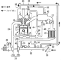
- FIG. 1 is a diagram illustrating a system configuration of a ventilation control device according to the present embodiment.
- the system of this embodiment includes an engine 10 as an internal combustion engine.
- the number of cylinders and the cylinder arrangement of the engine 10 are not particularly limited.
- the engine 10 includes a cylinder block 14 having a piston 12 therein.
- a cylinder head 16 is assembled to the upper part of the cylinder block 14.
- the cylinder head 16 is covered with a cylinder head cover 18.
- a space from the upper surface of the piston 12 to the cylinder head 16 forms a combustion chamber 20.
- the cylinder head 16 includes an intake passage 22 that communicates with the combustion chamber 20 and an exhaust passage 24.
- the system according to the present embodiment includes a supercharger 26.
- the supercharger 26 includes a turbine 26 a provided in the exhaust passage 24 and a compressor 26 b provided in the intake passage 22.
- the turbine 26a and the compressor 26b are connected to each other.
- the compressor 26b is driven by the turbine 26a that rotates by receiving the exhaust pressure, and the intake air is compressed and supercharged by the compressor 26b.
- the intake passage 22 is provided with an intercooler 28 for cooling the intake air supercharged by the compressor 26b.
- air bypass passages 30 and 32 for bypassing the compressor 26b are provided in the intake passage 22 upstream of the intercooler 28.
- ABV Air By-pass Valve
- An ejector 36 is provided in the air bypass passage 32. A detailed description of the ejector 36 will be described later.
- An air cleaner 38 is provided in the intake passage 22 upstream of the intercooler 28.
- an electronically controlled throttle valve 40 is provided in the intake passage 22 downstream of the intercooler 28.
- a surge tank 42 is provided in the intake passage 22 downstream of the throttle valve 40.
- the exhaust passage 24 is provided with an exhaust bypass passage 44 that bypasses the turbine 26a.
- the exhaust bypass passage 44 is provided with an electromagnetically driven WGV (Waste Gat Valve) 46. Since the back pressure can be adjusted by opening the WGV 46, the engine pump loss and the exhaust gas residual amount in the cylinder can be suppressed.
- WGV Wood Gat Valve
- the system of this embodiment is equipped with an EGR mechanism that recirculates exhaust gas from the exhaust passage 24 to the intake passage 22.
- the EGR mechanism includes an EGR passage 48 that connects the exhaust passage 24 upstream of the turbine 26 a and the surge tank 42.
- an EGR valve 50 for adjusting the amount of EGR gas, a water-cooled EGR cooler 52, and an EGR catalyst 54 are provided on the EGR passage 48.
- the EGR valve 50 is disposed at a position closest to the surge tank 42, and the EGR catalyst 54 is disposed at a position close to the exhaust passage 24.
- the EGR mechanism includes an ejector 56 between the EGR valve 50 and the EGR cooler 52. The detailed description of the ejector 56 will be described later together with the description of the ejector 36.
- the system of the present embodiment includes a blow-by gas reduction mechanism that reduces blow-by gas.
- the blow-by gas is a gas that flows into the crankcase through a gap between the piston 12 and the cylinder wall surface, and includes unburned fuel and oil mist.
- the blow-by gas reduction mechanism includes four types of PCV passages 58, 60, 62, and 64.
- the PCV passage 58 connects the cylinder head cover 18 and the surge tank 42.
- a PCV valve 66 is provided on the PCV passage 58.
- the PCV passage 60 connects the cylinder head cover 18 and the intake passage 22 on the upstream side of the compressor 26b.
- the PCV passage 62 connects the suction port 56 a of the ejector 56 and the cylinder head cover 18.
- a PCV valve 68 is provided on the PCV passage 62.
- the PCV passage 64 connects the suction port 36 a of the ejector 36 and the cylinder head cover 18.
- the system of the present embodiment includes an ECU (Electronic Control Unit) 70.
- ECU Electronic Control Unit
- Various sensors necessary for control of the engine 10 such as a throttle opening sensor for detecting the opening of the throttle valve 40 and a temperature sensor for detecting the coolant temperature of the engine 10 are connected to the input side of the ECU 70.
- Various actuators such as the ABV 34, the throttle valve 40, the WGV 46, and the EGR valve 50 are connected to the output side of the ECU 70.
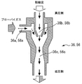
- FIG. 2 is a diagram for explaining the structure of the ejectors 36 and 56.
- the ejectors 36 and 56 include suction ports 36a and 56a, nozzle portions 36b and 56b, and diffuser portions 36c and 56c, respectively.
- the suction port 36 a is connected to one end of the PCV passage 64.
- the nozzle part 36b is connected to the air bypass passage 32 on the intercooler 28 side.
- the diffuser portion 36c is connected to the air bypass passage 32 on the air cleaner 38 side.
- the suction port 56 a is connected to one end of the PCV passage 62.
- the nozzle portion 56b is connected to the EGR passage 48 on the EGR cooler 52 side.
- the diffuser portion 56c is connected to the EGR passage 48 on the EGR valve 50 side.
- FIG. 3 is a diagram for explaining the flow of blow-by gas in the non-supercharging region.
- a negative pressure downstream of the throttle valve 40 can be ensured to some extent. Therefore, the gas in the crankcase flows into the surge tank 42 via the cylinder head cover 18 and the PCV passage 58. At this time, fresh air flows into the crankcase from the intake passage 22 via the PCV passage 60 and the cylinder head cover 18.
- FIG. 4 is a diagram for explaining the flow of blow-by gas in the supercharging region.
- the pressure on the downstream side of the compressor 26b is higher than the pressure on the upstream side. Therefore, a driving flow can be generated inside the ejector 36. Therefore, the gas in the crankcase can be sucked from the PCV passage 64 and introduced into the surge tank 42 via the air bypass passage 32 so that the engine 10 can be recombusted.
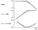
- FIG. 5 is a graph showing the relationship between the opening of the WGV 46, the opening of the throttle valve 40, the blow-by gas flow rate, and the supercharging pressure.
- the blow-by gas flow rate in FIG. 5 is the total amount of blow-by gas reintroduced into the engine 10.
- the blow-by gas flow rate decreases. Therefore, when the throttle opening is maximized, the blow-by gas flow rate becomes zero. If the opening of the WGV 46 is reduced at this time, the supercharging pressure can be increased, so that the flow of the driving flow inside the ejector 36 can be secured. Therefore, as shown by the broken line in FIG.
- FIG. 6 is a diagram showing the relationship between engine speed and torque.
- the solid line in FIG. 6 shows the engine characteristics when the ejector 36 is not mounted, and the broken line in the figure shows the engine characteristics when the ejector 36 is mounted.
- FIG. 6 in the high speed range, when the ejector 36 is mounted, the engine performance is deteriorated compared to when the ejector 36 is not mounted. This is because the back pressure increases and the turbo work increases by executing the above-described control for reducing the opening of the WGV 46.
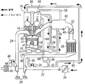
- FIG. 7 is a diagram for explaining the flow of blow-by gas when EGR gas is introduced.
- the pressure in the exhaust passage 24 becomes higher than the intake manifold pressure. Therefore, a driving flow can be generated inside the ejector 56.
- the gas in the crankcase can be sucked from the PCV passage 62, introduced into the surge tank 42 via the EGR passage 48, and recombusted by the engine 10. Therefore, the ventilation which solved the above-mentioned problem becomes possible.
- the crankcase can be ventilated in the entire range from the non-supercharged region to the supercharged region.
- FIG. 8 is a diagram showing the relationship among the intake pipe pressure (intake pressure) and the target supercharging pressure, the torque, and the EGR rate on the downstream side of the throttle valve 40.
- the intake pressure is negative in the region where the target boost pressure is low. Therefore, as described in FIG. 3, the gas in the crankcase can be introduced into the surge tank 42 via the PCV passage 58.
- the boost pressure can be used in a region where the target boost pressure is high. Therefore, as described in FIG. 4, the gas in the crankcase can be sucked from the PCV passage 64 and introduced into the surge tank 42 via the air bypass passage 32.
- the gas in the crankcase When introducing the EGR gas, the gas in the crankcase can be sucked from the PCV passage 62 and introduced into the surge tank 42 via the EGR passage 48. Therefore, the gas in the crankcase can be introduced into the surge tank 42 even in an intermediate load region where the intake manifold pressure is positive (that is, a region where the target boost pressure is medium). In addition, this EGR gas introduction can be performed regardless of the target boost pressure level. Therefore, according to this embodiment, ventilation in the crankcase can be performed in the entire range from the non-supercharged region to the supercharged region. Moreover, as shown in FIG. 8, according to this embodiment, the ventilable area of FIG. 3 and FIG. 4 and the ventilable area of FIG. 7 can be combined. Therefore, according to the present embodiment, the crankcase can be well ventilated in the entire range from the non-supercharged region to the supercharged region.
- the EGR passage 48 is the “first bypass passage” in the first invention
- the PCV passage 62 is the “first PCV passage” in the first invention
- the ejector 56 is the first This corresponds to the “first gas introduction means” in the first invention.
- the PCV valve 68 corresponds to the “PCV valve” in the third aspect of the invention.
- the air bypass passage 32 is the “second bypass passage” in the fifth invention
- the PCV passage 64 is the “second PCV passage” in the fifth invention
- the ejector 36 is the above This corresponds to the “fifth gas introduction means” in the fifth invention.
- Embodiment 2 of the present invention will be described with reference to FIG.
- the present embodiment is characterized in that the routine of FIG. 9 is executed in the system configuration described in the first embodiment.
- the control for closing the PCV valve 68 is executed when the crankcase internal pressure decreases when the EGR gas is introduced.
- the blow-through control is control for forcibly introducing the intake air in the intake passage 22 into the exhaust passage 24 via the EGR passage 48 for the purpose of improving the supercharging response.
- the above-described problem is caused by providing the ejector 56 in the EGR passage 48.
- water vapor is contained in the EGR gas.
- an EGR cooler 52 is provided in the EGR passage 48. Therefore, when the EGR gas is cooled by the EGR cooler 52 and the gas temperature is lowered, the water vapor may be condensed and liquefied and accumulated in the ejector 56.
- the water generated by the liquefaction can be discharged out of the ejector 56 together with the EGR gas by the flow of the EGR gas.
- the temperature of the EGR gas cooled by the EGR cooler 52 is further lowered, so that water generated by liquefaction may be frozen.
- ice generated by freezing accumulates in the ejector 56, the flow rate and pressure of the EGR gas are changed.
- the control for closing the PCV valve 68 is executed during the execution of the blow-by control.
- an unintended gas flow in which the gas in the crankcase flows into the exhaust passage 24 can be prevented in advance.
- the gas cooling in the EGR cooler 52 is stopped. Thereby, it is possible to prevent the water generated by liquefaction inside the ejector 56 from freezing.
- FIG. 9 is a flowchart showing a routine executed by the ECU 70 in the present embodiment. Note that the routine shown in FIG. 9 is repeatedly executed periodically.
- the ECU 70 determines whether or not it is during a cold start (step 100). Specifically, when there is a start request for the engine 10 and the cooling water temperature is equal to or lower than a predetermined temperature, it is determined that it is a cold start time. In this step, when it is determined that it is not during the cold start, the ECU 70 proceeds to step 120. On the other hand, if it is determined that it is during cold start, the ECU 70 stops the introduction of the cooling water to the EGR cooler 52 (step 110) and proceeds to step 120. Thereby, even if EGR gas is introduced, it is possible to prevent water from freezing inside the ejector 56.
- step 120 the ECU 70 determines whether or not it is during steady running. Specifically, when there is no request for a supercharging response, it is determined that the vehicle is in steady running. When it is determined in this step that the vehicle is in steady running, the ECU 70 proceeds to step 130. On the other hand, when it is determined that the vehicle is not in steady running, the ECU 70 stops the introduction of the cooling water to the EGR cooler 52 (step 140), opens the EGR valve 50 (step 150), and performs PCV to execute the blow-by control. The valve 68 is closed (step 160). As a result, ventilation through the ejector 56 is stopped (step 170).
- step 130 the ECU 70 determines whether or not EGR gas is introduced. If it is determined in this step that the EGR gas is not being introduced, the ECU 70 stops the introduction of the cooling water to the EGR cooler 52 in order to promote ventilation via the PCV passages 58, 60, 64 (step 180). The EGR valve 50 is closed (step 190), and the PCV valve 68 is closed (step 200). Thereby, the ventilation via the ejector 56 is stopped (step 210). On the other hand, if it is determined that EGR gas is being introduced, the ECU 70 introduces cooling water to the EGR cooler 52 (step 220), opens the EGR valve 50 (step 230), and opens the PCV valve 68 (step 240). . Thereby, ventilation via the ejector 56 is executed (step 250).
- the introduction of the cooling water to the EGR cooler 52 is stopped when it is determined that it is during the cold start, so even if the EGR gas is introduced during the cold start. Further, it is possible to prevent water from freezing inside the ejector 56. Further, since ventilation through the ejector 56 is stopped when it is determined that the vehicle is not in steady running, the gas in the crankcase can be prevented from flowing into the exhaust passage 24 during execution of the blow-by control. Further, when it is determined that the EGR gas is not being introduced, the ventilation via the ejector 56 is stopped, so that the ventilation via the PCV passages 58, 60, 64 can be promoted. Further, since ventilation through the ejector 56 is executed during steady running and when EGR gas is being introduced, the gas in the crankcase is sucked from the PCV passage 62 and burned in the engine 10 together with EGR gas and fresh air. it can.
- the ECU 70 executes the process of step 120 in FIG. 9 so that the “blow-through control determination means” in the second invention executes the process of step 160 in FIG.
- the “introduction prohibiting means” in the second invention is realized.
- the EGR cooler 52 corresponds to the “exhaust cooling means” in the fourth invention.
- the ECU 70 executes the process of step 100 in FIG. 9
- the “cold start determining means” in the fourth invention executes the process of step 110 in FIG. “Cooling prohibiting means” is realized.
Landscapes
- Engineering & Computer Science (AREA)
- Mechanical Engineering (AREA)
- General Engineering & Computer Science (AREA)
- Chemical & Material Sciences (AREA)
- Combustion & Propulsion (AREA)
- Physics & Mathematics (AREA)
- Thermal Sciences (AREA)
- Chemical Kinetics & Catalysis (AREA)
- Lubrication Details And Ventilation Of Internal Combustion Engines (AREA)
- Exhaust-Gas Circulating Devices (AREA)
Abstract
Priority Applications (5)
| Application Number | Priority Date | Filing Date | Title |
|---|---|---|---|
| CN201180074614.9A CN103906901B (zh) | 2011-10-31 | 2011-10-31 | 内燃机的换气控制装置 |
| JP2013524669A JP5527486B2 (ja) | 2011-10-31 | 2011-10-31 | 内燃機関の換気制御装置 |
| PCT/JP2011/075105 WO2013065112A1 (fr) | 2011-10-31 | 2011-10-31 | Dispositif de commande de ventilation pour moteur à combustion interne |
| US13/981,188 US8960167B2 (en) | 2011-10-31 | 2011-10-31 | Ventilation control apparatus for internal combustion engine |
| EP11875140.3A EP2775111B1 (fr) | 2011-10-31 | 2011-10-31 | Dispositif de commande de ventilation pour moteur à combustion interne |
Applications Claiming Priority (1)
| Application Number | Priority Date | Filing Date | Title |
|---|---|---|---|
| PCT/JP2011/075105 WO2013065112A1 (fr) | 2011-10-31 | 2011-10-31 | Dispositif de commande de ventilation pour moteur à combustion interne |
Publications (1)
| Publication Number | Publication Date |
|---|---|
| WO2013065112A1 true WO2013065112A1 (fr) | 2013-05-10 |
Family
ID=48191508
Family Applications (1)
| Application Number | Title | Priority Date | Filing Date |
|---|---|---|---|
| PCT/JP2011/075105 Ceased WO2013065112A1 (fr) | 2011-10-31 | 2011-10-31 | Dispositif de commande de ventilation pour moteur à combustion interne |
Country Status (5)
| Country | Link |
|---|---|
| US (1) | US8960167B2 (fr) |
| EP (1) | EP2775111B1 (fr) |
| JP (1) | JP5527486B2 (fr) |
| CN (1) | CN103906901B (fr) |
| WO (1) | WO2013065112A1 (fr) |
Cited By (8)
| Publication number | Priority date | Publication date | Assignee | Title |
|---|---|---|---|---|
| CN103397926A (zh) * | 2013-08-15 | 2013-11-20 | 安徽江淮汽车股份有限公司 | 一种增压汽油机的呼吸系统 |
| FR3008141A1 (fr) * | 2013-07-02 | 2015-01-09 | Peugeot Citroen Automobiles Sa | Circuit de gaz de carter d'un moteur thermique muni d'un clapet de regulation, moteur thermique et clapet de regulation correspondants |
| FR3016185A1 (fr) * | 2014-01-07 | 2015-07-10 | Peugeot Citroen Automobiles Sa | Moteur a combustion de vehicule automobile a systeme de degazage securise |
| WO2015111679A1 (fr) * | 2014-01-22 | 2015-07-30 | Toyota Jidosha Kabushiki Kaisha | Moteur à combustion interne |
| EP2913491A1 (fr) * | 2014-02-26 | 2015-09-02 | Toyota Jidosha Kabushiki Kaisha | Système et procédé de commande de moteur pour système de moteur |
| WO2015158819A1 (fr) * | 2014-04-17 | 2015-10-22 | Reinz-Dichtungs-Gmbh | Système de ventilation |
| WO2015162345A1 (fr) * | 2014-04-23 | 2015-10-29 | Renault S.A.S. | Raccord de circuit de reaspiration de gaz de blow-by pour moteur a combustion interne, notamment a essence |
| JP2017040176A (ja) * | 2015-08-18 | 2017-02-23 | トヨタ自動車株式会社 | 内燃機関の制御装置 |
Families Citing this family (29)
| Publication number | Priority date | Publication date | Assignee | Title |
|---|---|---|---|---|
| US20150345349A1 (en) * | 2012-10-08 | 2015-12-03 | Serge V. Monros | Diesel pollution control system |
| US9347368B2 (en) * | 2012-10-25 | 2016-05-24 | Ford Global Technologies, Llc | Method and system for fuel vapor management |
| US9359923B2 (en) * | 2012-10-25 | 2016-06-07 | Ford Global Technologies, Llc | Method and system for fuel vapor management |
| KR101496034B1 (ko) * | 2013-09-10 | 2015-02-25 | 지엠 글로벌 테크놀러지 오퍼레이션스 엘엘씨 | 차량용 크랭크케이스 환기장치 |
| JP2016104977A (ja) * | 2014-11-20 | 2016-06-09 | 株式会社デンソー | 内燃機関の排気循環装置 |
| US10174650B2 (en) * | 2014-11-21 | 2019-01-08 | Ford Global Technologies, Llc | Vehicle with integrated turbocharger oil control restriction |
| US9611810B2 (en) * | 2015-02-03 | 2017-04-04 | Robert Bosch Gmbh | Gaseous fuel mixer with exhaust gas recirculation |
| US9657659B2 (en) | 2015-02-20 | 2017-05-23 | Ford Global Technologies, Llc | Method for reducing air flow in an engine at idle |
| CN106032764B (zh) * | 2015-03-12 | 2019-02-15 | 日立汽车系统(苏州)有限公司 | 具有活塞漏气量收集功能的发动机系统 |
| JP6287956B2 (ja) * | 2015-05-22 | 2018-03-07 | トヨタ自動車株式会社 | 内燃機関 |
| US10100757B2 (en) | 2015-07-06 | 2018-10-16 | Ford Global Technologies, Llc | Method for crankcase ventilation in a boosted engine |
| DE102016111585A1 (de) * | 2015-07-07 | 2017-01-12 | Ford Global Technologies, Llc | Verfahren und System zum Kraftstoffdampfmanagement |
| CN105257368A (zh) * | 2015-11-30 | 2016-01-20 | 重庆小康工业集团股份有限公司 | 发动机油气分离系统 |
| WO2018022092A1 (fr) * | 2016-07-29 | 2018-02-01 | Cummins Inc. | Dispositif d'introduction de flux de charge |
| KR101927181B1 (ko) * | 2016-09-13 | 2018-12-10 | 현대자동차 주식회사 | 엔진 시스템 및 이를 이용한 제어 방법 |
| KR20180031517A (ko) * | 2016-09-20 | 2018-03-28 | 현대자동차주식회사 | 엔진 시스템 및 이를 이용한 제어 방법 |
| DE102016220770A1 (de) * | 2016-10-21 | 2018-04-26 | Elringklinger Ag | Abscheidevorrichtung, Motorvorrichtung und Abscheideverfahren |
| JP6547797B2 (ja) * | 2017-07-12 | 2019-07-24 | マツダ株式会社 | エンジンのシリンダヘッドカバー構造 |
| JP6528810B2 (ja) | 2017-07-14 | 2019-06-12 | マツダ株式会社 | エンジンのシリンダヘッドカバー構造 |
| CN111502800A (zh) * | 2019-01-30 | 2020-08-07 | 苏州达菲特过滤技术股份有限公司 | 带曲轴箱压力调节装置的呼吸器及柴油发动机 |
| US10995705B2 (en) * | 2019-02-07 | 2021-05-04 | Woodward, Inc. | Modular exhaust gas recirculation system |
| JP2021046956A (ja) * | 2019-09-17 | 2021-03-25 | いすゞ自動車株式会社 | 熱交換器及び内燃機関のブローバイガス処理装置 |
| CN213175878U (zh) | 2020-01-08 | 2021-05-11 | 伍德沃德有限公司 | 排气气体再循环混合器和发动机系统 |
| CN112211759A (zh) * | 2020-10-14 | 2021-01-12 | 哈尔滨工程大学 | 一种气体机爆震抑制装置及其抑制方法 |
| US11174809B1 (en) | 2020-12-15 | 2021-11-16 | Woodward, Inc. | Controlling an internal combustion engine system |
| US11215132B1 (en) | 2020-12-15 | 2022-01-04 | Woodward, Inc. | Controlling an internal combustion engine system |
| CN115013116A (zh) * | 2022-06-24 | 2022-09-06 | 东风汽车集团股份有限公司 | 车辆及发动机的保护装置、控制方法和计算机设备 |
| DE102023114215B3 (de) * | 2023-05-31 | 2024-10-17 | Bayerische Motoren Werke Aktiengesellschaft | Verbrennungskraftmaschine für ein Kraftfahrzeug sowie Kraftfahrzeug |
| JP2025070693A (ja) * | 2023-10-20 | 2025-05-02 | ヤンマーホールディングス株式会社 | エンジン装置 |
Citations (11)
| Publication number | Priority date | Publication date | Assignee | Title |
|---|---|---|---|---|
| JPS56109645U (fr) * | 1980-01-23 | 1981-08-25 | ||
| JPS63158516U (fr) * | 1987-04-04 | 1988-10-18 | ||
| JPH07279640A (ja) | 1994-04-11 | 1995-10-27 | Osaka Gas Co Ltd | ガスエンジン |
| JP2006226159A (ja) | 2005-02-16 | 2006-08-31 | Toyota Motor Corp | 可変バルブタイミング機構を備えたエンジンのブローバイガス還元装置 |
| JP2007138790A (ja) | 2005-11-17 | 2007-06-07 | Toyota Motor Corp | エンジンの冷却媒体循環装置 |
| JP2008101472A (ja) * | 2006-10-17 | 2008-05-01 | Yamaha Motor Co Ltd | 火花点火式多気筒エンジン |
| JP2008232091A (ja) | 2007-03-23 | 2008-10-02 | Nissan Diesel Motor Co Ltd | 過給器付内燃機関の排気還流装置 |
| JP2009002286A (ja) | 2007-06-22 | 2009-01-08 | Toyota Motor Corp | 内燃機関の排気還流装置 |
| JP2009133292A (ja) * | 2007-12-03 | 2009-06-18 | Aisan Ind Co Ltd | 過給機付き内燃機関の負圧発生装置 |
| JP2010285937A (ja) * | 2009-06-11 | 2010-12-24 | Toyota Motor Corp | 内燃機関のブローバイガス処理装置 |
| JP2011094557A (ja) * | 2009-09-30 | 2011-05-12 | Aisan Industry Co Ltd | ブローバイガス還元装置 |
Family Cites Families (7)
| Publication number | Priority date | Publication date | Assignee | Title |
|---|---|---|---|---|
| US5611204A (en) * | 1993-11-12 | 1997-03-18 | Cummins Engine Company, Inc. | EGR and blow-by flow system for highly turbocharged diesel engines |
| JP2001073881A (ja) * | 1999-08-31 | 2001-03-21 | Honda Motor Co Ltd | 内燃機関の吸気装置 |
| DE102005059668A1 (de) * | 2005-12-12 | 2007-06-14 | Mahle International Gmbh | Brennkraftmaschine |
| DE102006019634B4 (de) * | 2006-04-25 | 2019-04-25 | Mahle International Gmbh | Entlüftungseinrichtung für eine aufgeladene Brennkraftmaschine |
| JP4297175B2 (ja) * | 2006-10-06 | 2009-07-15 | トヨタ自動車株式会社 | ブローバイガス処理装置 |
| JP4933491B2 (ja) * | 2008-06-17 | 2012-05-16 | 愛三工業株式会社 | ブローバイガス還元装置 |
| US9382825B2 (en) * | 2013-04-25 | 2016-07-05 | Ford Global Technologies, Llc | System and method for gas purge control |
-
2011
- 2011-10-31 CN CN201180074614.9A patent/CN103906901B/zh not_active Expired - Fee Related
- 2011-10-31 US US13/981,188 patent/US8960167B2/en not_active Expired - Fee Related
- 2011-10-31 JP JP2013524669A patent/JP5527486B2/ja not_active Expired - Fee Related
- 2011-10-31 WO PCT/JP2011/075105 patent/WO2013065112A1/fr not_active Ceased
- 2011-10-31 EP EP11875140.3A patent/EP2775111B1/fr not_active Not-in-force
Patent Citations (11)
| Publication number | Priority date | Publication date | Assignee | Title |
|---|---|---|---|---|
| JPS56109645U (fr) * | 1980-01-23 | 1981-08-25 | ||
| JPS63158516U (fr) * | 1987-04-04 | 1988-10-18 | ||
| JPH07279640A (ja) | 1994-04-11 | 1995-10-27 | Osaka Gas Co Ltd | ガスエンジン |
| JP2006226159A (ja) | 2005-02-16 | 2006-08-31 | Toyota Motor Corp | 可変バルブタイミング機構を備えたエンジンのブローバイガス還元装置 |
| JP2007138790A (ja) | 2005-11-17 | 2007-06-07 | Toyota Motor Corp | エンジンの冷却媒体循環装置 |
| JP2008101472A (ja) * | 2006-10-17 | 2008-05-01 | Yamaha Motor Co Ltd | 火花点火式多気筒エンジン |
| JP2008232091A (ja) | 2007-03-23 | 2008-10-02 | Nissan Diesel Motor Co Ltd | 過給器付内燃機関の排気還流装置 |
| JP2009002286A (ja) | 2007-06-22 | 2009-01-08 | Toyota Motor Corp | 内燃機関の排気還流装置 |
| JP2009133292A (ja) * | 2007-12-03 | 2009-06-18 | Aisan Ind Co Ltd | 過給機付き内燃機関の負圧発生装置 |
| JP2010285937A (ja) * | 2009-06-11 | 2010-12-24 | Toyota Motor Corp | 内燃機関のブローバイガス処理装置 |
| JP2011094557A (ja) * | 2009-09-30 | 2011-05-12 | Aisan Industry Co Ltd | ブローバイガス還元装置 |
Non-Patent Citations (1)
| Title |
|---|
| See also references of EP2775111A4 |
Cited By (15)
| Publication number | Priority date | Publication date | Assignee | Title |
|---|---|---|---|---|
| FR3008141A1 (fr) * | 2013-07-02 | 2015-01-09 | Peugeot Citroen Automobiles Sa | Circuit de gaz de carter d'un moteur thermique muni d'un clapet de regulation, moteur thermique et clapet de regulation correspondants |
| CN103397926A (zh) * | 2013-08-15 | 2013-11-20 | 安徽江淮汽车股份有限公司 | 一种增压汽油机的呼吸系统 |
| FR3016185A1 (fr) * | 2014-01-07 | 2015-07-10 | Peugeot Citroen Automobiles Sa | Moteur a combustion de vehicule automobile a systeme de degazage securise |
| CN106414986A (zh) * | 2014-01-22 | 2017-02-15 | 丰田自动车株式会社 | 内燃发动机 |
| WO2015111679A1 (fr) * | 2014-01-22 | 2015-07-30 | Toyota Jidosha Kabushiki Kaisha | Moteur à combustion interne |
| JP2015137590A (ja) * | 2014-01-22 | 2015-07-30 | トヨタ自動車株式会社 | 内燃機関 |
| US10393072B2 (en) | 2014-01-22 | 2019-08-27 | Toyota Jidosha Kabushiki Kaisha | Internal combustion engine |
| CN106414986B (zh) * | 2014-01-22 | 2018-09-11 | 丰田自动车株式会社 | 内燃发动机 |
| JP2015161180A (ja) * | 2014-02-26 | 2015-09-07 | トヨタ自動車株式会社 | 機関システムの制御装置 |
| EP2913491A1 (fr) * | 2014-02-26 | 2015-09-02 | Toyota Jidosha Kabushiki Kaisha | Système et procédé de commande de moteur pour système de moteur |
| US9988957B2 (en) | 2014-04-17 | 2018-06-05 | Reinz-Dichtungs-Gmbh | Ventilation system for an internal combustion engine |
| WO2015158819A1 (fr) * | 2014-04-17 | 2015-10-22 | Reinz-Dichtungs-Gmbh | Système de ventilation |
| FR3020413A1 (fr) * | 2014-04-23 | 2015-10-30 | Renault Sas | Raccord de circuit de reaspiration de gaz de blow-by pour moteur a combustion interne, notamment a essence |
| WO2015162345A1 (fr) * | 2014-04-23 | 2015-10-29 | Renault S.A.S. | Raccord de circuit de reaspiration de gaz de blow-by pour moteur a combustion interne, notamment a essence |
| JP2017040176A (ja) * | 2015-08-18 | 2017-02-23 | トヨタ自動車株式会社 | 内燃機関の制御装置 |
Also Published As
| Publication number | Publication date |
|---|---|
| CN103906901A (zh) | 2014-07-02 |
| JPWO2013065112A1 (ja) | 2015-04-02 |
| EP2775111B1 (fr) | 2016-08-17 |
| EP2775111A1 (fr) | 2014-09-10 |
| US20140224232A1 (en) | 2014-08-14 |
| US8960167B2 (en) | 2015-02-24 |
| JP5527486B2 (ja) | 2014-06-18 |
| EP2775111A4 (fr) | 2015-07-15 |
| CN103906901B (zh) | 2016-04-27 |
Similar Documents
| Publication | Publication Date | Title |
|---|---|---|
| JP5527486B2 (ja) | 内燃機関の換気制御装置 | |
| JP6007504B2 (ja) | ディーゼルエンジン | |
| JP5812102B2 (ja) | 過給機付き内燃機関 | |
| EP3290667B1 (fr) | Dispositif de traitement de gaz de soufflage pour moteur à combustion interne équipé d'un compresseur d'alimentation | |
| JP5822445B2 (ja) | ブローバイガス還流装置 | |
| JP5092962B2 (ja) | 過給機付き内燃機関の制御装置 | |
| US10738721B2 (en) | Blow-by gas supply device for engine | |
| JP2013096247A (ja) | 内燃機関の制御装置 | |
| JP4525544B2 (ja) | 過給機付き内燃機関 | |
| JP2012067614A (ja) | コンプレッサ出口圧力制御装置 | |
| JP2013164053A (ja) | 内燃機関の制御装置 | |
| WO2007066833A1 (fr) | Systeme d’epuration de gaz d’echappement pour moteur a combustion interne | |
| US7584748B2 (en) | Exhaust gas recirculation system for an internal combustion engine | |
| JP2008261257A (ja) | 内燃機関のegrシステム | |
| KR102417386B1 (ko) | 엔진의 흡기계의 수분 배출 시스템 및 방법 | |
| JP5280113B2 (ja) | 多気筒内燃機関における排気ガス還流装置 | |
| JP2012237231A (ja) | ブローバイガス還流装置 | |
| JP2012171565A (ja) | ラムエア調節装置 | |
| JP2018184870A (ja) | エンジンの制御装置 | |
| JP2016031063A (ja) | 過給機付きエンジンの排気還流装置 | |
| JP2011241694A (ja) | 排気還流装置 | |
| JP2011202591A (ja) | ブローバイガス還流装置 | |
| JP2009209816A (ja) | 内燃機関の制御装置 | |
| JP2005264759A (ja) | ブローバイガス還流装置 | |
| KR100867812B1 (ko) | V형 디젤엔진 병렬 2단 터보차져 블로바이가스 재순환장치 |
Legal Events
| Date | Code | Title | Description |
|---|---|---|---|
| WWE | Wipo information: entry into national phase |
Ref document number: 201180074614.9 Country of ref document: CN |
|
| ENP | Entry into the national phase |
Ref document number: 2013524669 Country of ref document: JP Kind code of ref document: A |
|
| REEP | Request for entry into the european phase |
Ref document number: 2011875140 Country of ref document: EP |
|
| WWE | Wipo information: entry into national phase |
Ref document number: 2011875140 Country of ref document: EP |
|
| 121 | Ep: the epo has been informed by wipo that ep was designated in this application |
Ref document number: 11875140 Country of ref document: EP Kind code of ref document: A1 |
|
| WWE | Wipo information: entry into national phase |
Ref document number: 13981188 Country of ref document: US |
|
| NENP | Non-entry into the national phase |
Ref country code: DE |