WO2013065507A1 - Structure de palier pour composant électronique de type à opération rotationnelle - Google Patents
Structure de palier pour composant électronique de type à opération rotationnelle Download PDFInfo
- Publication number
- WO2013065507A1 WO2013065507A1 PCT/JP2012/077116 JP2012077116W WO2013065507A1 WO 2013065507 A1 WO2013065507 A1 WO 2013065507A1 JP 2012077116 W JP2012077116 W JP 2012077116W WO 2013065507 A1 WO2013065507 A1 WO 2013065507A1
- Authority
- WO
- WIPO (PCT)
- Prior art keywords
- bearing
- shaft
- rotor
- holder
- bearing structure
- Prior art date
- Legal status (The legal status is an assumption and is not a legal conclusion. Google has not performed a legal analysis and makes no representation as to the accuracy of the status listed.)
- Ceased
Links
Images







Classifications
-
- H—ELECTRICITY
- H01—ELECTRIC ELEMENTS
- H01C—RESISTORS
- H01C10/00—Adjustable resistors
- H01C10/30—Adjustable resistors the contact sliding along resistive element
- H01C10/32—Adjustable resistors the contact sliding along resistive element the contact moving in an arcuate path
- H01C10/36—Adjustable resistors the contact sliding along resistive element the contact moving in an arcuate path structurally combined with switching arrangements
-
- H—ELECTRICITY
- H01—ELECTRIC ELEMENTS
- H01H—ELECTRIC SWITCHES; RELAYS; SELECTORS; EMERGENCY PROTECTIVE DEVICES
- H01H19/00—Switches operated by an operating part which is rotatable about a longitudinal axis thereof and which is acted upon directly by a solid body external to the switch, e.g. by a hand
- H01H19/02—Details
- H01H19/10—Movable parts; Contacts mounted thereon
- H01H19/14—Operating parts, e.g. turn knob
-
- H—ELECTRICITY
- H01—ELECTRIC ELEMENTS
- H01H—ELECTRIC SWITCHES; RELAYS; SELECTORS; EMERGENCY PROTECTIVE DEVICES
- H01H3/00—Mechanisms for operating contacts
- H01H3/02—Operating parts, i.e. for operating driving mechanism by a mechanical force external to the switch
- H01H3/0213—Combined operation of electric switch and variable impedance, e.g. resistor, capacitor
Definitions
- the present invention mainly relates to a bearing structure of a rotary operation type electronic component used as a rotary switch or a variable resistor of a portable electronic device such as a wireless device.
- the bearing structure adopted in a rotary switch, a variable resistor, or the like is a structure in which a shaft is simply inserted into a bearing as shown in Patent Document 1 and Patent Document 2, for example. For this reason, there is no configuration for reducing the axial or radial play of the shaft, and the play is determined by the dimensional accuracy of the bearing and the shaft.
- Patent Document 3 discloses a rotary switch having a bearing structure in which an O-ring is sandwiched between the inner wall surface of the case and the outer peripheral surface of the rotating body for waterproofing.
- the bearing structure can suppress radial play, but cannot prevent axial play.
- the operation knob is large enough to satisfy the ease of operation. Therefore, the shaft play at the knob operation position is increased by the size of the knob, and the operator is not given a smooth feeling during the knob operation.
- an object of the present invention is to provide a bearing structure for a rotary operation type electronic component that can suppress backlash in the axial direction and radial direction.
- a rotating operation type electronic component bearing structure includes a columnar operation portion, a step portion formed from one end of the operation portion, a small outer diameter and an axially extending holding portion and the holding portion. Further, the bearing includes a rotation operation shaft including a driving portion extended in the axial direction, and a bearing having a shaft hole through which the holding portion is inserted and rotatably held, and one end facing the step portion.
- An electromechanical signal control unit that performs signal control by rotation of a rotor fixed to the drive unit is provided at the other end of the drive unit.
- a first taper surface extending to the outer peripheral surface of the shaft hole is formed on the inner peripheral edge of the shaft hole at one end of the bearing, and a second taper surface having an inner diameter increasing toward the outside is formed on the bearing.
- An annular ring spring that is sandwiched and cut between the second taper surfaces is mounted and held.
- the outer peripheral fixed ring formed annular grooves in the driver-side end portion is a retaining of the rotary operation shaft by engaging the other end of the bearing is mounted in.
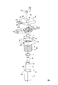
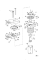
- FIG. 1 is an exploded perspective view of a rotary switch that is a first embodiment to which the present invention is applied.
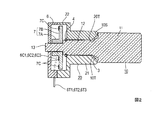
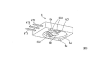
- FIG. FIG. 2 is an axial sectional view of the embodiment of FIG. 1. The perspective view seen from the accommodation recessed part 23 side of the holder 6 in FIG. The disassembled perspective view of the variable resistor which is 2nd Example to which this invention is applied.
- FIG. 5 is an axial sectional view of the embodiment of FIG. 4.
- 6A is a perspective view of the holder 6 ′ in FIG. 5 as viewed from the accommodation recess 23 side
- FIG. 6B is a plan view of the holder 6 ′ in FIG. 5 as viewed from the accommodation recess 23 side.
- the perspective view of rotor 7 ' which shows the modification of the Example of FIG.
- FIG. 9 is an axial sectional view of the rotary switch of FIG. 8.
- 10A is a perspective view of the click spring in FIG. 9 and the click spring support plate before attaching the click spring
- FIG. 10B is a perspective view of the click spring support plate after the click spring is attached.
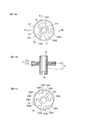
- 11A is a top view of the rotor in FIG. 9,
- FIG. 11B is a sectional view of the rotor in FIG. 9,
- FIG. 11C is a bottom view of the rotor in FIG. 12A is a diagram showing a connection pattern of the upper and lower contact pieces in FIG. 9, and
- FIG. 12B is a diagram showing a sliding contact piece formed by folding the connection pattern.
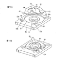
- FIG. 13A is a bottom view of the lower holder
- FIG. 13B is a top view of the upper holder.
- FIG. 1 An exploded perspective view of an embodiment of a rotary switch to which a bearing structure according to the present invention is applied is shown in FIG. 1, and an axial sectional view thereof is shown in FIG.
- the rotary switch includes a columnar rotation operation shaft 10, a bearing 20 through which the rotation operation shaft 10 is inserted, a rotor 7 that is mounted and fixed on the rotation operation shaft 10, and a holder 6.
- a columnar rotation operation shaft 10 a bearing 20 through which the rotation operation shaft 10 is inserted
- a rotor 7 that is mounted and fixed on the rotation operation shaft 10
- a holder 6. Have.
- the rotation operation shaft 10 is made of resin or metal, and has a columnar operation portion 11 having an outer peripheral surface chamfered in parallel to the axial direction, and the diameter is reduced from one end of the operation portion 11 and extends in the axial direction.
- a cylindrical holding portion 12 and a cylindrical driving portion 13 having a diameter further reduced from one end of the holding portion 12 and extending in the axial direction are coaxially provided.
- the end surface on the holding portion 12 side of the operation portion 11 forms a stepped portion 10S in the radial direction from the outer peripheral edge of the operation portion 11, and a tapered surface 10T extending from the radial intermediate position of the stepped portion 10S to the outer peripheral surface of the holding portion 12 is formed.
- An annular groove 12 a is formed on the outer periphery adjacent to the end surface of the holding portion 12 on the side opposite to the operation portion 11.
- the drive unit 13 is chamfered on both sides of the shaft center line in parallel with the axial direction, and thus the cross section perpendicular to the shaft center line has a shape in which two opposite sides of the quadrilateral are arcs.
- the bearing 20 is formed of resin or metal, and has a cylindrical portion 21 having an inner diameter smaller than the outer diameter of the operation portion 11 of the rotation operation shaft 10 and having a shaft hole 24 through which the holding portion 12 is inserted, and one end of the cylindrical portion 21. And a substantially rectangular parallelepiped housing portion 22. Screws are formed on the outer peripheral surface of the cylindrical portion 21 so as to be attached to a casing of a device in which the rotary switch is used.
- a tapered surface 20T is formed on the inner peripheral edge of the shaft hole 24 at the distal end of the cylindrical portion 21 so that the inner diameter increases toward the outside of the shaft hole 24 in the axial direction.
- the housing portion 22 communicates with the shaft hole 24, is formed with a circular accommodating recess 23 having a larger diameter concentrically with the shaft hole 24, and is opened on the surface opposite to the cylindrical portion 21.
- the tapered surface 10T formed in the stepped portion 10S and the tapered surface 20T formed in the cylindrical portion 21 are in a relation that the angle is opened toward the stepped portion 10S as shown in the cross section of FIG.
- the inner diameter is substantially equal to the outer diameter of the holding portion 12, the outer diameter is smaller than the outer diameter of the operation portion 11 of the rotation operation shaft 10, the cross section formed of a metal spring material is circular, and a cut annular ring spring 3 is elastically sandwiched between the tapered surfaces 10T and 20T and attached to the rotation operating shaft 10, and the holding portion 12 is inserted into the shaft hole 24 of the bearing 20, and in this state, protrudes into the housing recess 23.
- An annular groove 12 a at the end of the holding portion 12 is fitted with a spring metal fixing ring 4 whose outer diameter is larger than the inner diameter of the shaft hole 24 and whose ring is cut, and the housing recess 23 adjacent to the shaft hole 24.
- the rotational operation shaft 10 is prevented from coming off by engaging with the bottom surface 23a.
- the ring spring 3 sandwiched between the taper surfaces 10T and 20T is elastically pressed toward the step portion 10S by the taper surface 20T, and is elastically deformed so that the cut ring is opened.
- an external force in the axial direction and / or radial direction is applied to the rotation operation shaft 10
- the ring spring 3 is further pushed up toward the step portion 10S, further deforms so as to open the ring, and closes the ring against this.
- the elastic force resists the external force by pushing the ring spring 3 back against the tapered surface 20T in the axial direction.
- the backlash of the rotation operation shaft 10 in the axial direction and the radial direction with respect to the bearing 20 is elastically suppressed. Therefore, the operator can obtain a smooth rotational operation feeling.
- the rotor 7 is made of resin, and is formed integrally with a rotation shaft 7A in which a shaft hole 7D having the same cross-sectional shape as the cross section of the drive unit 13 of the rotation operation shaft 10 is formed and coaxially with the rotation shaft 7A. And a disk portion 7B having a plate surface perpendicular to the axial direction, and is rotatably disposed in the housing recess 23 of the housing portion 22.
- a sliding contact piece 7C formed by punching a metal plate so as to be flush with the surface of the disk portion 7B opposite to the bearing 20 is attached by integral molding.
- the holder 6 is made of resin and has a rectangular parallelepiped shape that is perpendicular to the axial direction, and is placed on the housing part 22 from the top of the rotor 7. As shown in a perspective view from the housing portion 22 side in FIG. 3, the holder 6 has a circular housing recess 6A formed on the surface on the housing portion 22 side so as to extend the housing recess 23, and the holder 6 is placed at the center. A penetrating shaft hole 6D is formed.
- the elastic contacts 6C1, 6C2, and the two elastic contacts 6C3 protrude inward from the inner peripheral surface of the housing recess 6A, and the set of the elastic contact 6C1, one elastic contact 6C3, the set of the elastic contact 6C2, and the other elastic contact 6C3 is an axis.
- the elastic contacts 6C1, 6C2, and 6C3 are located on opposite sides of the hole 6D, and are bent so that their tip portions protrude outward from the opening of the housing recess 6A.
- the other ends of the elastic contacts 6C1 and 6C2 protrude outward from the side surface of the holder 6, and are made terminals 6T1 and 6T2, respectively.
- the other elastic contacts 6C3 are integrated at the other end, and project from the side surface of the holder 6 as terminals 6T3.
- the drive portion 13 protruding into the housing recess 23 is inserted into the shaft hole 7D of the rotor 7 so that the disk portion 7B of the rotor 7 is disposed in the housing recess 23, and the tip of the drive portion 13 is the shaft hole 6D of the holder 6. From the top of the rotor 7 so as to close the housing recess 23, and the fixing pin 8 is inserted into the fixing hole 6a of the holder 6 and the fixing hole 22a of the housing portion 22 to insert the tip.
- the rotary switch is assembled by caulking with rivets.
- Rotating the operation unit 11 of the rotating operation shaft 10 rotates the rotor 7.
- the tips of the elastic contacts 6C1, 6C2 and 6C3 provided on the holder 6 are located at different radial positions from the axis center of the rotation operation shaft 10. That is, in this example, the two elastic contacts 6C3 sharing the terminal 6T3 are located on both sides of the rotating shaft 7A of the rotor 7, and the distal ends of the elastic contacts 6C1 and 6C2 are located further outward in the radial direction.
- the rotor 7 is in sliding contact with the sliding contact piece 7C provided on the plate surface of the disk portion 7B by the rotation of the rotor 7.
- the sliding contact piece 7C conducts between the terminals 6T1 and 6T3 in the first predetermined rotation angle range (a plurality of rotations) of the rotor 7, and a second predetermined rotation angle range (a plurality may exist).
- the number of sliding contact pieces 7C, the respective arc angles, the radial position and width, etc. are determined so that the terminals 6T2 and 6T3 are electrically connected.
- the pressing force applied to the ring spring 3 by the tapered surface 20T can be set as desired, so that the ring spring is between the tapered surfaces 10T and 20T. 3 can be set as desired, and an appropriate rotational operation feeling can be given to the operator.
- FIG. 4 is an exploded perspective view of the embodiment applied to a variable resistor, and FIG.
- This variable resistor has a rotation operation shaft 10, a bearing 20, a rotor 7 ', a holder 6', a ring spring 3, a fixing ring 4, and a fixing pin 8, and FIGS. Only the rotor 7 'and the holder 6' are different from the first embodiment. Therefore, the following description will focus on the different parts, and the description of the common parts will be omitted as much as possible.
- the rotor 7 ′ has a rotating shaft 7A and a disk portion 7B as in the rotor 7 of FIG. 1, but the sliding contact piece 7′C is replaced by a disk portion instead of the sliding contact piece 7C in FIG. It is attached to the plate surface of 7B.
- the sliding contact piece 7′C is formed by pressing with an elastic metal plate so as to sandwich the rotating shaft 7A from the substantially semimoon-shaped base portion 7′Cb and the side edge of the base portion 7′Cb on the rotating shaft 7A side.
- Two contacts 7'C1 that are bent to be separated from the plate surface of the disk portion 7B, and are extended from the side edge of the base portion 7'Cb outside the two contacts 7'C1 and the disk portion 7B.
- a contact 7′C2 bent away from the plate surface.
- the base portion 7′Cb is fixed by press-fitting a not-shown protrusion protruding from the plate surface of the disk portion 7B into a fixing hole 7′Aa formed in the base portion.
- the tips of the contacts 7'C1 and 7'C2 are folded back to the plate surface side of the disk portion 7B, and convex bent portions 7'C1a and 7'C2a are formed on the holder 6 'side. It becomes a point.
- These bent portions 7'C1a and 7'C2a are arranged in a straight line orthogonal to the rotation center line, and the bent portions 7'C1a of the two contacts 7'C1 are located on both sides adjacent to the rotating shaft 7A.
- the bent portion 7′C2a of the contact 7′C2 is located radially outward from the bent portion 7′C1a of the one contact.
- the metal plate is pressed so as to surround the shaft hole 6D on the bottom surface 6B of the housing recess 6A.
- the common conductor ring 6C formed in the above and the arc-shaped strip-shaped resistor 6R provided concentrically at intervals outside the common conductor ring 6C are attached. Both ends of the resistor 6R are connected to terminals 6T1 and 6T2, respectively.
- a terminal 6T3 extends integrally from the common conductor ring 6C through both ends of the resistor 6R.
- the bent portion 7'C1a of the two contacts 7'C1 of the sliding contact piece 7'C is in elastic contact with the common conductor ring 6C, and the bent portion 7 of the contact 7'C2 is provided.
- 'C2a makes elastic contact with the resistor 6R. Therefore, when the rotor 7 'rotates, the electrical resistance between the terminals 6T1 and 6T3 and the electrical resistance between the terminals 6T2 and 6T3 change.
- a resistor 6R and a common conductor ring 6C are provided on the bottom surface 6B of the receiving recess 6A of the holder 6 ', and contacts 7'C1, 7'C2 are provided on the disk portion 7B of the rotor 7'.
- a sliding contact piece 7′C having Conversely, as shown in FIG. 7, as shown in FIG. 7, an arc belt-like resistor 7R is provided on the plate surface of the disk portion 7B of the rotor 7 ′, and a common conductor ring 7Cc is provided on the inside thereof, and the holder 6 shown in FIG.
- the resistor 7R and the common conductor ring 7Cc are brought into sliding contact with the elastic contacts 6C1 and 6C3, respectively.
- the elastic contact 6C2 and the terminal 6T2 are not provided.
- one end of the resistor 7R is connected to the common conductor ring 7Cc.
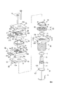
- FIG. 8 shows an exploded perspective view of an embodiment in which the bearing structure according to the present invention is applied to a rotary switch disclosed in Patent Document 1
- FIG. 9 shows an axial sectional view of the rotary switch. 1, 2 and 3
- the rotary switch of this embodiment is configured to give the operator a click feeling at every desired rotation angle interval of the rotary operation shaft 10 and to increase the number of switches. It is a thing.
- the rotary switch includes a rotation operation shaft 10, a ring spring 3, a bearing 20, a click disc 30, a click spring 40, a click spring support plate 50, and a lower holder 80.
- a combination of the upper holder 60 and the cover 90 corresponds to the holder 6 in FIG. 1, and in this embodiment, a lower holder 80 having an elastic contact is further provided to increase the number of switches.
- the rotation operation shaft 10 has the same structure as the rotation operation shaft 10 in FIG. 1, is formed into a cylindrical shape by processing a metal rod, is extended coaxially from the operation portion 11 and the tip thereof, and has a diameter from the operation portion 11. And a drive unit 13 that extends coaxially from the tip of the holding unit 12 and has a smaller diameter than the holding unit 12.
- An annular groove 12 a is formed on the outer peripheral surface adjacent to the tip of the holding portion 12.
- the drive unit 13 is formed with at least one flat surface 13a formed by being cut off in parallel with the central axis. In the illustrated example, two parallel planes are formed symmetrically with respect to the rotation center of the rotation operation shaft 10.
- the bearing 20 has a cylindrical portion 21 in which mounting screws are formed on the outer periphery, and a rectangular housing portion 22 formed integrally with one end of the cylindrical portion 21.
- a shaft hole 24 through which the holding portion 12 of the rotation operation shaft 10 is rotatably inserted is formed in the bearing 20 through the cylindrical portion 21.
- fixing holes 22 a are formed in one set of diagonal portions, and positioning holes 22 b are formed in another set of diagonal portions.
- a circular accommodating recess 23 is formed in the center of the upper surface of the housing portion 22 coaxially with the cylindrical portion 21, and a shaft hole 24 is concentrically opened on the bottom surface thereof.
- the fixing ring 4 is attached to the annular groove 12a of the part to prevent it from coming off.
- the housing portion 22 accommodates the click disk 30.
- the click disk 30 has a shaft portion 31 at the center thereof, and unevenness is arranged in the circumferential direction on the outer upper surface of the shaft portion 31 by ridges 32 extending radially.
- a shaft hole 33 into which the rotation shaft 71 of the rotor 70 is inserted is formed in the shaft portion 31 in the axial direction.
- the shaft hole 31 protrudes from one place on the inner periphery of the shaft hole 33 toward the center.
- An engagement key 34 extending in the direction is formed.
- the front end face toward the center of the engagement key 34 is a flat surface that comes into contact with and engages with the flat surface 13 a of the drive unit 13, and the drive unit 13 inserted through the shaft hole 33 when the rotation operation shaft 10 is rotated.
- the click disk 30 is rotated by engaging the flat surface 13a with the tip flat surface of the engagement key 34.
- the annular click spring 40 is formed by punching a spring metal plate, and engagement protrusions 41 projecting toward the click disk 30 are formed at two positions on one diameter of the annular portion, and the diameter is further increased. And two fixed terminals 42 extending outwardly from each other on two lines on the other diameter perpendicular to the diameter.
- the fixed terminal 42 is bent to the opposite side of the click disk 30 at approximately 45 ° with respect to the plate surface at the intermediate portion.
- the click spring 40 is bent by 45 °, whereby the engagement of a click spring support plate 50, which will be described later, with a locking groove 55 can be shallowed, and thus the thickness of the click spring support plate 50 can be reduced.
- the click spring 40 is attached to the lower surface of the click spring support plate 50.
- 10A and 10B show perspective views before and after the click spring 40 is attached. However, here, the set of the click spring 40 and the click spring support plate 50 in FIG. 8 is shown rotated by 180 ° about the center line 5X.
- the click spring support plate 50 has the same rectangular shape as the housing portion 22, and an annular recess 52 that receives the ring-shaped click spring 40 is formed on the lower surface thereof, and a shaft hole 51 is formed in the center.
- the diameter of the shaft hole 51 is a diameter through which a rotation shaft 71 of a rotor 70 described later can be rotatably inserted.
- Two positioning holes 53b are formed adjacent to one side of the click spring support plate 50, fixing holes 53a are formed in the vicinity of one set of diagonal portions, and the lower surface in the vicinity of another set of diagonal portions is formed. Each is formed with a positioning projection 54.
- the two fixed terminals 42 of the click spring 40 are inserted and locked in locking grooves 55 formed extending from the fixing holes 53a of the click spring support plate 50 in the center direction.
- the click spring support plate 50 is attached to the upper surface of the housing portion 22 by inserting the drive portion 13 through the shaft hole 51 and closing the accommodation recess 23 accommodating the click disc 30 from above.
- the positioning protrusion 54 of the click spring support plate 50 is press-fitted and fixed in the positioning hole 22 b on the upper surface of the housing portion 22.
- FIG. 11A is a top view of the rotor 70
- FIG. 11B is a cross-sectional view taken along the line 11B-11B in FIG. 11A
- FIG. 11C is a bottom view rotated by 180 ° about the line 11B-11B in FIG.
- the elastic contact and the sliding contact piece can be brought into contact with and detached from both the one surface and the other surface of the disk portion of the rotor. Yes. That is, the rotor 70 is located in the middle of the rotational axis 71, the longitudinal axis of the rotational shaft 71, the disk portion 72 coaxial with the rotational shaft 71, and the sliding contact piece 7 ⁇ / b> C held by the disk portion 72.
- a shaft hole 73 having the same cross-sectional shape as the shaft hole 33 of the click disc 30 is formed in the rotation shaft 71. Further, a notch 74 is formed by cutting one circular arc portion of the lower end of the rotating shaft 71 by a predetermined length in the axial direction from the lower end. In the notch 74, the rotation shaft 71 is fitted into the engagement key 34 in the shaft hole 33 of the click disk 30 through the shaft hole 51, whereby the rotation shaft 71 is fitted in the axial direction of the notch 74. Only the length is inserted into the shaft hole 33a.
- the sliding contact piece 7C is composed of an upper contact piece 7C1 and a lower contact piece 7C2, and a pattern of upper and lower contact pieces 7C1 and 7C2 connected to each other obtained by punching one metal plate as shown in FIG. 12A. As shown in FIG. 12B, and the lower contact piece 7C2 is overlaid on the lower side of the upper contact piece 7C1.
- the upper and lower contact pieces 7C1 and 7C2 are formed in a pattern inscribed in a common circle C1 indicated by a broken line in FIG. 12B.
- the circles C2, C3 are concentric with the circle C1 and gradually decrease in diameter.
- the annular bands B1, B2, B3 adjacent to each other having a width sandwiched by C4 are defined, and a desired number of desired lengths (angle ranges) in the circumferential direction within these annular bands B1, B2, B3, respectively.
- a contact piece pattern in which each arc region is a contact piece region is determined in advance.
- the annular band B1 is filled with one contact piece region C1a having a predetermined angular range and an empty region G1a having the remaining angular range.
- the annular band B2 is filled with two contact piece regions C1b1 and C1b2 each having a predetermined angle range, and empty regions G1b1 and G1b2 between adjacent two contact piece regions.
- the annular band B3 is filled with one (360 °) empty region G1c.
- the contact piece regions C1a, C1b1, and C1b2 are regions where the metal surface of the contact piece 7C1 is exposed, and the empty regions G1a, G1b1, G1b2, and G1c are the insulation of the disk portion 72 that is in the same plane as the surface of the contact piece region. It is the body surface.
- the annular band B1 has four contact piece regions C2a1, C2a2, C2a3, C2a4 each having a predetermined angular range, and an empty space between the four contact piece regions. It is filled with regions G2a1, G2a2, G2a3, G2a4.
- the annular band B2 is filled with two contact piece regions C2b1 and C2b2 each having a predetermined angle range, and empty regions G2b1 and G2b2 between adjacent two contact piece regions.
- the annular band B3 is filled with one (360 °) contact piece region C2c.
- the contact piece regions C2a1, C2a2, C2a3, C2a4, C2b1, C2b2, and C2c are regions where the metal surface of the contact piece is exposed, and the empty regions G2a1, G2a2, G2a3, G2a4, G2b1, G2b1, and G2b2 Is the surface of the insulator of the disk portion 72 in the same plane.
- the upper holder 60 and the lower holder 80 have the same structure, and the holder formed as the same part can be used for the upper side and the lower side by changing the vertical direction.
- the cover 90 and the click spring support plate 50 have exactly the same structure.
- FIG. 13A shows the lower surface of the lower holder 80 and a part of the lower surface of the rotor 70 visible above.
- a circular rotor accommodating recess 82 is formed on the upper surface of the lower holder 80, and a substantially rectangular window 81 is formed on the floor of the rotor accommodating recess 82.
- an engaging protrusion 85 protruding from the lower surface to the upper holder 60 side, and the engaging protrusion
- An engaging recess 86 is formed adjacent to the portion 85 and having the same width and the side wall portion cut off.
- Fixing holes 84a are formed in the vicinity of one set of diagonal portions of the lower holder 80, and positioning holes 84b are formed in the vicinity of another set of diagonal portions. Further, two positioning projections 83 are formed adjacent to one side from which the terminals 8T1, 8T2, and 8T3 are led out.
- the lower holder 80 is formed by insert molding together with the three elastic contacts 8C1, 8C2, and 8C3 and the terminals 8T1, 8T2, and 8T3 projecting outward from one side of the lower holder 80.
- the three elastic contacts 8C1, 8C2, and 8C3 extend inward from the edge of the window 81, and their tips are located on the annular bands B1, B2, B3 defined on the sliding contact piece 7C of the rotor 70, respectively. Yes.
- Each of the elastic contacts 8C1, 8C2, and 8C3 has two branch arms, and the contact stability (reliability) and life are improved by making two contact points in each annular band.
- FIG. 13B shows the upper surface of the upper holder 60 and a part of the upper surface of the rotor 70 that can be seen below.
- the structure of the upper holder 60 is exactly the same as that of the lower holder 80.
- a circular rotor accommodating recess 62 is formed on the lower surface of the substantially rectangular upper holder 60 which is the same as the housing part 22, and a substantially rectangular window 61 is formed on the ceiling of the rotor accommodating recess 62.
- Fixing holes 64a are formed in one set of diagonal portions of the upper holder 60, and positioning holes 64b are formed in another set of diagonal portions. Further, two positioning protrusions 63 are formed adjacent to one side from which the terminals 6T1, 6T2, and 6T3 are led out.
- the upper holder 60 is formed by insert molding together with the three elastic contacts 6C1, 6C2, and 6C3 and the terminals 6T1, 6T2, and 6T3 which are integrally extended from them and protrude outward from one side of the upper holder 60.
- the three elastic contacts 6C1, 6C2, 6C3 extend inward from the edge of the window 61, and their tips are respectively located on the annular bands B1, B2, B3 defined on the sliding contact piece 7C of the rotor 70. Yes.
- each of the elastic contacts 6C1, 6C2, and 6C3 has two branch arms, and contacts at two points in each annular band.
- the positioning protrusion 83 (see FIG. 13A) of the lower holder 80 is fitted into the positioning hole 53 b of the click spring support plate 50, and the lower holder 80 is positioned and fixed on the click spring support plate 50.
- the drive portion 13 of the rotating operation shaft 10 is inserted into the shaft hole 73 of the rotor 70 so that the substantially lower half of the disk portion 72 of the rotor 70 is disposed in the rotor accommodating recess 82 of the lower holder 80. Is inserted and engaged with the shaft hole 33 of the click disc 30 through the shaft hole 51 of the click spring support plate 50.
- the upper holder 60 is placed over the rotor 70 so that the upper half of the disk portion 72 of the rotor 70 is accommodated in the rotor accommodating recess 62 of the upper holder 60, and is fixed to the lower holder 80 in an overlapping manner.
- the engaging convex portion 65 and the engaging concave portion 66 (see FIG. 13B) of the upper holder 60 are fitted into the engaging concave portion 86 and the engaging convex portion 85 of the lower holder 80, respectively, and are positioned with respect to each other.
- the upper end portion of the rotating shaft 71 of the rotor 70 is inserted into the shaft hole 91 of the cover 90, the cover 90 is overlaid on the upper holder 60, and the positioning projection 94 is fitted into the positioning hole 64b, thereby positioning the positioning hole 93b.
- the positioning projection 63 is fitted to the base.
- the drive unit 13 is inserted into the shaft hole 73 of the rotating shaft 71 of the rotor 70 through which the click disk 30 and the click spring support plate 50 are inserted, and the cover 90 It is supported in the shaft hole 91.
- the cross section perpendicular to the axial center of the shaft hole 73 of the rotor 70 has a shape obtained by cutting a circular arc in a straight line in the same manner as the cross section of the drive unit 13.
- the click disk 30 is also rotated.
- the projection 41 of the click spring 40 fixed to the click spring support plate 50 engages with the radial irregularities of the rotating click disk 30 to cause a click feeling when the rotating operation shaft 10 is rotated.
- the contact piece regions are separately determined within 360 ° in the annular regions that are different in the radial direction separately on the upper surface and the lower surface of the disk portion of the rotor 70. Therefore, there is an advantage that the degree of freedom in design is high. That is, there is a high degree of freedom in which the opening / closing angle range and relative timing of the plurality of switches can be designed according to demand.
- the case where the annular bands B1, B2, B3 are defined in common for the upper and lower contact pieces 7C1, 7C2 of the rotor 70 has been shown.
- the upper and lower holders 60 and 80 may be separately defined for the upper and lower sides, and the number and arrangement of the elastic contacts of the upper holder 60 and the lower holder 80 may be determined in accordance with the respective annular bands.
- FIG. 14 shows a fourth embodiment of the rotary switch according to the present invention.
- the lower holder 80 is integrally formed with the elastic contacts 8C1, 8C2, and 8C3 by insert molding, and then the elastic contacts 8C1, 8C2, and 8C3 are bent at a desired angle in the window 81.
- the holder 80 and the click spring support plate 50 are separated from each other.
- the lower holder 80 and the click spring support plate 50 may be formed as a lower holder (first holder) 80 ′ integrated with each other.
- the upper holder 60 and the cover 90 in the third embodiment may be formed as an upper holder (second holder) 60 ′ integrated with each other as shown in FIG. Since other configurations are the same as those of the third embodiment, the description is omitted.
- FIG. 15 is a block diagram of a rotary operation type electronic component for conceptualizing and explaining the above-described various embodiments and modifications to which the bearing structure according to the present invention is applied.
- the cylindrical rotation operation shaft 100 is coaxial with an operation unit 110 that receives a rotation operation, a holding unit 120 that has a smaller diameter than the operation unit 110 and extends coaxially, and an outer diameter that is further reduced from the holding unit 120.
- the boundary between the operation unit 110 and the holding unit 120 forms a stepped portion 100S.
- the holding portion 120 is rotatably inserted into the shaft hole 230 of the bearing 200 from one end side of the bearing 200, and a fixing ring 400 fixed on the outer periphery of the rear end portion of the holding portion 120 is formed in the shaft hole 230 at the other end of the bearing 200. Engage with the outer periphery.
- the drive part 130 extended from the holding part 120 rotates the rotor 700 in the electromechanical signal control part 600 provided at the other end of the bearing 200.
- the electromechanical signal control unit 600 is a variable resistance mechanism that causes a resistance change due to sliding between the contact and the resistor by the rotation of the rotor 700, or a switch operation by contact between the elastic contact and the contact sliding piece, or separation. And a signal applied to the terminal 6T is controlled by electromechanical control.
- the electromechanical signal control unit 600 corresponds to the configuration including the holders 6 and 6 ', the rotors 7 and 7', and the housing unit 22 that accommodates the holders 6 and 6 'in the embodiment of FIGS. This corresponds to a configuration including the upper holders 80 and 80 ′, the lower holders 60 and 60 ′, and the rotor 70 accommodated therebetween in the example. *
- the bearing structure of the present invention is formed with a tapered surface 100T extending from the radial intermediate position of the step portion 100S of the rotation operation shaft 100 to the outer peripheral surface of the holding portion 120, and at the bearing end surface facing the step portion 100S.
- the ring spring 300 is configured to be pressed against the tapered surface 100T by a tapered surface 200T having a diameter increasing toward the outside formed on the inner peripheral edge of the shaft hole 240.
- the tapered surfaces 100T and 200T are angled so as to open toward the stepped portion 100S in the axial cross section.
- the ratio of distributing the external force applied from the tapered surface 200T to the ring spring 300 to the axial component and the radial component can be changed by changing the inclination angles of the tapered surfaces 100T and 200T.
Landscapes
- Engineering & Computer Science (AREA)
- Power Engineering (AREA)
- Microelectronics & Electronic Packaging (AREA)
- Rotary Switch, Piano Key Switch, And Lever Switch (AREA)
- Adjustable Resistors (AREA)
Abstract
Priority Applications (4)
| Application Number | Priority Date | Filing Date | Title |
|---|---|---|---|
| HK14107570.7A HK1194201B (en) | 2011-11-04 | 2012-10-19 | Bearing structure for rotary control-type electronic component |
| JP2013541703A JP5852669B2 (ja) | 2011-11-04 | 2012-10-19 | 回転操作型電子部品の軸受構造 |
| CN201280046808.2A CN103843094B (zh) | 2011-11-04 | 2012-10-19 | 旋转操作式电子部件的轴承结构 |
| KR1020147007987A KR101900897B1 (ko) | 2011-11-04 | 2012-10-19 | 회전 조작형 전자 부품의 베어링 구조 |
Applications Claiming Priority (2)
| Application Number | Priority Date | Filing Date | Title |
|---|---|---|---|
| JP2011-241999 | 2011-11-04 | ||
| JP2011241999 | 2011-11-04 |
Publications (1)
| Publication Number | Publication Date |
|---|---|
| WO2013065507A1 true WO2013065507A1 (fr) | 2013-05-10 |
Family
ID=48191862
Family Applications (1)
| Application Number | Title | Priority Date | Filing Date |
|---|---|---|---|
| PCT/JP2012/077116 Ceased WO2013065507A1 (fr) | 2011-11-04 | 2012-10-19 | Structure de palier pour composant électronique de type à opération rotationnelle |
Country Status (5)
| Country | Link |
|---|---|
| JP (1) | JP5852669B2 (fr) |
| KR (1) | KR101900897B1 (fr) |
| CN (1) | CN103843094B (fr) |
| TW (1) | TWI521154B (fr) |
| WO (1) | WO2013065507A1 (fr) |
Cited By (1)
| Publication number | Priority date | Publication date | Assignee | Title |
|---|---|---|---|---|
| WO2023210221A1 (fr) * | 2022-04-25 | 2023-11-02 | 東京コスモス電機株式会社 | Composant électronique et appareil électronique |
Families Citing this family (3)
| Publication number | Priority date | Publication date | Assignee | Title |
|---|---|---|---|---|
| WO2018158905A1 (fr) * | 2017-03-02 | 2018-09-07 | 東京コスモス電機株式会社 | Composant d'actionnement rotatif |
| JP7006227B2 (ja) * | 2017-12-15 | 2022-01-24 | ヤマハ株式会社 | 操作装置 |
| CN109411285A (zh) * | 2018-11-27 | 2019-03-01 | 深圳和而泰智能控制股份有限公司 | 一种机械式开关结构 |
Citations (3)
| Publication number | Priority date | Publication date | Assignee | Title |
|---|---|---|---|---|
| JPH0433121U (fr) * | 1990-07-13 | 1992-03-18 | ||
| JPH0452704U (fr) * | 1990-09-10 | 1992-05-06 | ||
| JP2000082360A (ja) * | 1998-07-07 | 2000-03-21 | Yazaki Corp | 操作スイッチの操作内容表示装置 |
Family Cites Families (4)
| Publication number | Priority date | Publication date | Assignee | Title |
|---|---|---|---|---|
| JPH0724849B2 (ja) * | 1986-01-20 | 1995-03-22 | 新日本製鐵株式会社 | 板圧延における形状制御方法 |
| JP3698270B2 (ja) * | 1995-04-13 | 2005-09-21 | 朝日松下電工株式会社 | ロータリースイッチ |
| JP2003272487A (ja) * | 2002-03-19 | 2003-09-26 | Alps Electric Co Ltd | 複合操作型電気部品 |
| JP2006147403A (ja) * | 2004-11-22 | 2006-06-08 | Alps Electric Co Ltd | 回転操作型電気部品 |
-
2012
- 2012-10-12 TW TW101137710A patent/TWI521154B/zh not_active IP Right Cessation
- 2012-10-19 JP JP2013541703A patent/JP5852669B2/ja not_active Expired - Fee Related
- 2012-10-19 KR KR1020147007987A patent/KR101900897B1/ko active Active
- 2012-10-19 CN CN201280046808.2A patent/CN103843094B/zh active Active
- 2012-10-19 WO PCT/JP2012/077116 patent/WO2013065507A1/fr not_active Ceased
Patent Citations (3)
| Publication number | Priority date | Publication date | Assignee | Title |
|---|---|---|---|---|
| JPH0433121U (fr) * | 1990-07-13 | 1992-03-18 | ||
| JPH0452704U (fr) * | 1990-09-10 | 1992-05-06 | ||
| JP2000082360A (ja) * | 1998-07-07 | 2000-03-21 | Yazaki Corp | 操作スイッチの操作内容表示装置 |
Cited By (1)
| Publication number | Priority date | Publication date | Assignee | Title |
|---|---|---|---|---|
| WO2023210221A1 (fr) * | 2022-04-25 | 2023-11-02 | 東京コスモス電機株式会社 | Composant électronique et appareil électronique |
Also Published As
| Publication number | Publication date |
|---|---|
| JP5852669B2 (ja) | 2016-02-03 |
| KR20140096026A (ko) | 2014-08-04 |
| KR101900897B1 (ko) | 2018-09-21 |
| TW201335501A (zh) | 2013-09-01 |
| JPWO2013065507A1 (ja) | 2015-04-02 |
| CN103843094A (zh) | 2014-06-04 |
| TWI521154B (zh) | 2016-02-11 |
| CN103843094B (zh) | 2016-03-02 |
| HK1194201A1 (zh) | 2014-10-10 |
Similar Documents
| Publication | Publication Date | Title |
|---|---|---|
| JP4759071B2 (ja) | 回転型スイッチ | |
| JP2014116125A (ja) | 回転操作型電子部品 | |
| JP5852669B2 (ja) | 回転操作型電子部品の軸受構造 | |
| JP5852668B2 (ja) | 回転操作型電子部品の軸受構造 | |
| JP4891654B2 (ja) | プッシュスイッチ付き回転型電気部品 | |
| KR20160015194A (ko) | 전기 부품의 클릭 기구 | |
| EP1342983B1 (fr) | Capteur de rotation | |
| WO2013065447A1 (fr) | Mécanisme à clic de composant électrique | |
| HK1194201B (en) | Bearing structure for rotary control-type electronic component | |
| HK1194200B (en) | Bearing structure for rotary control-type electronic component | |
| JP7187066B2 (ja) | 回転式電子部品用摺動子 | |
| JP2014229365A (ja) | 押圧式多段スイッチ | |
| JP2000348567A (ja) | 回転型電気部品 | |
| JP7317356B2 (ja) | 自動復帰機構ユニット | |
| JP2019114621A (ja) | 2連形接触式ポテンショメータ | |
| HK1164536B (en) | Rotary switch | |
| JP2018156781A (ja) | 回転操作型電子部品 | |
| JP2008159907A (ja) | 回転式電子部品 | |
| JP2007134223A (ja) | 回転型電気部品 | |
| JP2019139967A (ja) | スイッチ装置 | |
| TW201447950A (zh) | 電子零件的掣子機構 | |
| JP2012043575A (ja) | 回転式スイッチ |
Legal Events
| Date | Code | Title | Description |
|---|---|---|---|
| 121 | Ep: the epo has been informed by wipo that ep was designated in this application |
Ref document number: 12846545 Country of ref document: EP Kind code of ref document: A1 |
|
| ENP | Entry into the national phase |
Ref document number: 2013541703 Country of ref document: JP Kind code of ref document: A |
|
| ENP | Entry into the national phase |
Ref document number: 20147007987 Country of ref document: KR Kind code of ref document: A |
|
| NENP | Non-entry into the national phase |
Ref country code: DE |
|
| 122 | Ep: pct application non-entry in european phase |
Ref document number: 12846545 Country of ref document: EP Kind code of ref document: A1 |