WO2013065748A1 - Dispositif de propulsion de véhicule - Google Patents
Dispositif de propulsion de véhicule Download PDFInfo
- Publication number
- WO2013065748A1 WO2013065748A1 PCT/JP2012/078189 JP2012078189W WO2013065748A1 WO 2013065748 A1 WO2013065748 A1 WO 2013065748A1 JP 2012078189 W JP2012078189 W JP 2012078189W WO 2013065748 A1 WO2013065748 A1 WO 2013065748A1
- Authority
- WO
- WIPO (PCT)
- Prior art keywords
- bearing
- rotor
- axial direction
- radial direction
- axial
- Prior art date
- Legal status (The legal status is an assumption and is not a legal conclusion. Google has not performed a legal analysis and makes no representation as to the accuracy of the status listed.)
- Ceased
Links
Images

Classifications
-
- F—MECHANICAL ENGINEERING; LIGHTING; HEATING; WEAPONS; BLASTING
- F16—ENGINEERING ELEMENTS AND UNITS; GENERAL MEASURES FOR PRODUCING AND MAINTAINING EFFECTIVE FUNCTIONING OF MACHINES OR INSTALLATIONS; THERMAL INSULATION IN GENERAL
- F16H—GEARING
- F16H47/00—Combinations of mechanical gearing with fluid clutches or fluid gearing
- F16H47/06—Combinations of mechanical gearing with fluid clutches or fluid gearing the fluid gearing being of the hydrokinetic type
-
- B—PERFORMING OPERATIONS; TRANSPORTING
- B60—VEHICLES IN GENERAL
- B60K—ARRANGEMENT OR MOUNTING OF PROPULSION UNITS OR OF TRANSMISSIONS IN VEHICLES; ARRANGEMENT OR MOUNTING OF PLURAL DIVERSE PRIME-MOVERS IN VEHICLES; AUXILIARY DRIVES FOR VEHICLES; INSTRUMENTATION OR DASHBOARDS FOR VEHICLES; ARRANGEMENTS IN CONNECTION WITH COOLING, AIR INTAKE, GAS EXHAUST OR FUEL SUPPLY OF PROPULSION UNITS IN VEHICLES
- B60K6/00—Arrangement or mounting of plural diverse prime-movers for mutual or common propulsion, e.g. hybrid propulsion systems comprising electric motors and internal combustion engines
- B60K6/20—Arrangement or mounting of plural diverse prime-movers for mutual or common propulsion, e.g. hybrid propulsion systems comprising electric motors and internal combustion engines the prime-movers consisting of electric motors and internal combustion engines, e.g. HEVs
- B60K6/22—Arrangement or mounting of plural diverse prime-movers for mutual or common propulsion, e.g. hybrid propulsion systems comprising electric motors and internal combustion engines the prime-movers consisting of electric motors and internal combustion engines, e.g. HEVs characterised by apparatus, components or means specially adapted for HEVs
- B60K6/26—Arrangement or mounting of plural diverse prime-movers for mutual or common propulsion, e.g. hybrid propulsion systems comprising electric motors and internal combustion engines the prime-movers consisting of electric motors and internal combustion engines, e.g. HEVs characterised by apparatus, components or means specially adapted for HEVs characterised by the motors or the generators
-
- B—PERFORMING OPERATIONS; TRANSPORTING
- B60—VEHICLES IN GENERAL
- B60K—ARRANGEMENT OR MOUNTING OF PROPULSION UNITS OR OF TRANSMISSIONS IN VEHICLES; ARRANGEMENT OR MOUNTING OF PLURAL DIVERSE PRIME-MOVERS IN VEHICLES; AUXILIARY DRIVES FOR VEHICLES; INSTRUMENTATION OR DASHBOARDS FOR VEHICLES; ARRANGEMENTS IN CONNECTION WITH COOLING, AIR INTAKE, GAS EXHAUST OR FUEL SUPPLY OF PROPULSION UNITS IN VEHICLES
- B60K6/00—Arrangement or mounting of plural diverse prime-movers for mutual or common propulsion, e.g. hybrid propulsion systems comprising electric motors and internal combustion engines
- B60K6/20—Arrangement or mounting of plural diverse prime-movers for mutual or common propulsion, e.g. hybrid propulsion systems comprising electric motors and internal combustion engines the prime-movers consisting of electric motors and internal combustion engines, e.g. HEVs
- B60K6/22—Arrangement or mounting of plural diverse prime-movers for mutual or common propulsion, e.g. hybrid propulsion systems comprising electric motors and internal combustion engines the prime-movers consisting of electric motors and internal combustion engines, e.g. HEVs characterised by apparatus, components or means specially adapted for HEVs
- B60K6/36—Arrangement or mounting of plural diverse prime-movers for mutual or common propulsion, e.g. hybrid propulsion systems comprising electric motors and internal combustion engines the prime-movers consisting of electric motors and internal combustion engines, e.g. HEVs characterised by apparatus, components or means specially adapted for HEVs characterised by the transmission gearings
-
- B—PERFORMING OPERATIONS; TRANSPORTING
- B60—VEHICLES IN GENERAL
- B60K—ARRANGEMENT OR MOUNTING OF PROPULSION UNITS OR OF TRANSMISSIONS IN VEHICLES; ARRANGEMENT OR MOUNTING OF PLURAL DIVERSE PRIME-MOVERS IN VEHICLES; AUXILIARY DRIVES FOR VEHICLES; INSTRUMENTATION OR DASHBOARDS FOR VEHICLES; ARRANGEMENTS IN CONNECTION WITH COOLING, AIR INTAKE, GAS EXHAUST OR FUEL SUPPLY OF PROPULSION UNITS IN VEHICLES
- B60K6/00—Arrangement or mounting of plural diverse prime-movers for mutual or common propulsion, e.g. hybrid propulsion systems comprising electric motors and internal combustion engines
- B60K6/20—Arrangement or mounting of plural diverse prime-movers for mutual or common propulsion, e.g. hybrid propulsion systems comprising electric motors and internal combustion engines the prime-movers consisting of electric motors and internal combustion engines, e.g. HEVs
- B60K6/22—Arrangement or mounting of plural diverse prime-movers for mutual or common propulsion, e.g. hybrid propulsion systems comprising electric motors and internal combustion engines the prime-movers consisting of electric motors and internal combustion engines, e.g. HEVs characterised by apparatus, components or means specially adapted for HEVs
- B60K6/40—Arrangement or mounting of plural diverse prime-movers for mutual or common propulsion, e.g. hybrid propulsion systems comprising electric motors and internal combustion engines the prime-movers consisting of electric motors and internal combustion engines, e.g. HEVs characterised by apparatus, components or means specially adapted for HEVs characterised by the assembly or relative disposition of components
-
- B—PERFORMING OPERATIONS; TRANSPORTING
- B60—VEHICLES IN GENERAL
- B60K—ARRANGEMENT OR MOUNTING OF PROPULSION UNITS OR OF TRANSMISSIONS IN VEHICLES; ARRANGEMENT OR MOUNTING OF PLURAL DIVERSE PRIME-MOVERS IN VEHICLES; AUXILIARY DRIVES FOR VEHICLES; INSTRUMENTATION OR DASHBOARDS FOR VEHICLES; ARRANGEMENTS IN CONNECTION WITH COOLING, AIR INTAKE, GAS EXHAUST OR FUEL SUPPLY OF PROPULSION UNITS IN VEHICLES
- B60K6/00—Arrangement or mounting of plural diverse prime-movers for mutual or common propulsion, e.g. hybrid propulsion systems comprising electric motors and internal combustion engines
- B60K6/20—Arrangement or mounting of plural diverse prime-movers for mutual or common propulsion, e.g. hybrid propulsion systems comprising electric motors and internal combustion engines the prime-movers consisting of electric motors and internal combustion engines, e.g. HEVs
- B60K6/22—Arrangement or mounting of plural diverse prime-movers for mutual or common propulsion, e.g. hybrid propulsion systems comprising electric motors and internal combustion engines the prime-movers consisting of electric motors and internal combustion engines, e.g. HEVs characterised by apparatus, components or means specially adapted for HEVs
- B60K6/40—Arrangement or mounting of plural diverse prime-movers for mutual or common propulsion, e.g. hybrid propulsion systems comprising electric motors and internal combustion engines the prime-movers consisting of electric motors and internal combustion engines, e.g. HEVs characterised by apparatus, components or means specially adapted for HEVs characterised by the assembly or relative disposition of components
- B60K6/405—Housings
-
- B—PERFORMING OPERATIONS; TRANSPORTING
- B60—VEHICLES IN GENERAL
- B60K—ARRANGEMENT OR MOUNTING OF PROPULSION UNITS OR OF TRANSMISSIONS IN VEHICLES; ARRANGEMENT OR MOUNTING OF PLURAL DIVERSE PRIME-MOVERS IN VEHICLES; AUXILIARY DRIVES FOR VEHICLES; INSTRUMENTATION OR DASHBOARDS FOR VEHICLES; ARRANGEMENTS IN CONNECTION WITH COOLING, AIR INTAKE, GAS EXHAUST OR FUEL SUPPLY OF PROPULSION UNITS IN VEHICLES
- B60K6/00—Arrangement or mounting of plural diverse prime-movers for mutual or common propulsion, e.g. hybrid propulsion systems comprising electric motors and internal combustion engines
- B60K6/20—Arrangement or mounting of plural diverse prime-movers for mutual or common propulsion, e.g. hybrid propulsion systems comprising electric motors and internal combustion engines the prime-movers consisting of electric motors and internal combustion engines, e.g. HEVs
- B60K6/42—Arrangement or mounting of plural diverse prime-movers for mutual or common propulsion, e.g. hybrid propulsion systems comprising electric motors and internal combustion engines the prime-movers consisting of electric motors and internal combustion engines, e.g. HEVs characterised by the architecture of the hybrid electric vehicle
- B60K6/48—Parallel type
-
- B—PERFORMING OPERATIONS; TRANSPORTING
- B60—VEHICLES IN GENERAL
- B60K—ARRANGEMENT OR MOUNTING OF PROPULSION UNITS OR OF TRANSMISSIONS IN VEHICLES; ARRANGEMENT OR MOUNTING OF PLURAL DIVERSE PRIME-MOVERS IN VEHICLES; AUXILIARY DRIVES FOR VEHICLES; INSTRUMENTATION OR DASHBOARDS FOR VEHICLES; ARRANGEMENTS IN CONNECTION WITH COOLING, AIR INTAKE, GAS EXHAUST OR FUEL SUPPLY OF PROPULSION UNITS IN VEHICLES
- B60K6/00—Arrangement or mounting of plural diverse prime-movers for mutual or common propulsion, e.g. hybrid propulsion systems comprising electric motors and internal combustion engines
- B60K6/20—Arrangement or mounting of plural diverse prime-movers for mutual or common propulsion, e.g. hybrid propulsion systems comprising electric motors and internal combustion engines the prime-movers consisting of electric motors and internal combustion engines, e.g. HEVs
- B60K6/50—Architecture of the driveline characterised by arrangement or kind of transmission units
- B60K6/54—Transmission for changing ratio
-
- B—PERFORMING OPERATIONS; TRANSPORTING
- B60—VEHICLES IN GENERAL
- B60W—CONJOINT CONTROL OF VEHICLE SUB-UNITS OF DIFFERENT TYPE OR DIFFERENT FUNCTION; CONTROL SYSTEMS SPECIALLY ADAPTED FOR HYBRID VEHICLES; ROAD VEHICLE DRIVE CONTROL SYSTEMS FOR PURPOSES NOT RELATED TO THE CONTROL OF A PARTICULAR SUB-UNIT
- B60W10/00—Conjoint control of vehicle sub-units of different type or different function
- B60W10/02—Conjoint control of vehicle sub-units of different type or different function including control of driveline clutches
- B60W10/024—Conjoint control of vehicle sub-units of different type or different function including control of driveline clutches including control of torque converters
- B60W10/026—Conjoint control of vehicle sub-units of different type or different function including control of driveline clutches including control of torque converters of lock-up clutches
-
- F—MECHANICAL ENGINEERING; LIGHTING; HEATING; WEAPONS; BLASTING
- F16—ENGINEERING ELEMENTS AND UNITS; GENERAL MEASURES FOR PRODUCING AND MAINTAINING EFFECTIVE FUNCTIONING OF MACHINES OR INSTALLATIONS; THERMAL INSULATION IN GENERAL
- F16H—GEARING
- F16H41/00—Rotary fluid gearing of the hydrokinetic type
- F16H41/24—Details
-
- F—MECHANICAL ENGINEERING; LIGHTING; HEATING; WEAPONS; BLASTING
- F16—ENGINEERING ELEMENTS AND UNITS; GENERAL MEASURES FOR PRODUCING AND MAINTAINING EFFECTIVE FUNCTIONING OF MACHINES OR INSTALLATIONS; THERMAL INSULATION IN GENERAL
- F16D—COUPLINGS FOR TRANSMITTING ROTATION; CLUTCHES; BRAKES
- F16D25/00—Fluid-actuated clutches
- F16D25/06—Fluid-actuated clutches in which the fluid actuates a piston incorporated in, i.e. rotating with the clutch
- F16D25/062—Fluid-actuated clutches in which the fluid actuates a piston incorporated in, i.e. rotating with the clutch the clutch having friction surfaces
- F16D25/063—Fluid-actuated clutches in which the fluid actuates a piston incorporated in, i.e. rotating with the clutch the clutch having friction surfaces with clutch members exclusively moving axially
- F16D25/0635—Fluid-actuated clutches in which the fluid actuates a piston incorporated in, i.e. rotating with the clutch the clutch having friction surfaces with clutch members exclusively moving axially with flat friction surfaces, e.g. discs
- F16D25/0638—Fluid-actuated clutches in which the fluid actuates a piston incorporated in, i.e. rotating with the clutch the clutch having friction surfaces with clutch members exclusively moving axially with flat friction surfaces, e.g. discs with more than two discs, e.g. multiple lamellae
-
- F—MECHANICAL ENGINEERING; LIGHTING; HEATING; WEAPONS; BLASTING
- F16—ENGINEERING ELEMENTS AND UNITS; GENERAL MEASURES FOR PRODUCING AND MAINTAINING EFFECTIVE FUNCTIONING OF MACHINES OR INSTALLATIONS; THERMAL INSULATION IN GENERAL
- F16H—GEARING
- F16H45/00—Combinations of fluid gearings for conveying rotary motion with couplings or clutches
- F16H45/02—Combinations of fluid gearings for conveying rotary motion with couplings or clutches with mechanical clutches for bridging a fluid gearing of the hydrokinetic type
- F16H2045/021—Combinations of fluid gearings for conveying rotary motion with couplings or clutches with mechanical clutches for bridging a fluid gearing of the hydrokinetic type three chamber system, i.e. comprising a separated, closed chamber specially adapted for actuating a lock-up clutch
-
- F—MECHANICAL ENGINEERING; LIGHTING; HEATING; WEAPONS; BLASTING
- F16—ENGINEERING ELEMENTS AND UNITS; GENERAL MEASURES FOR PRODUCING AND MAINTAINING EFFECTIVE FUNCTIONING OF MACHINES OR INSTALLATIONS; THERMAL INSULATION IN GENERAL
- F16H—GEARING
- F16H45/00—Combinations of fluid gearings for conveying rotary motion with couplings or clutches
- F16H45/02—Combinations of fluid gearings for conveying rotary motion with couplings or clutches with mechanical clutches for bridging a fluid gearing of the hydrokinetic type
- F16H2045/0273—Combinations of fluid gearings for conveying rotary motion with couplings or clutches with mechanical clutches for bridging a fluid gearing of the hydrokinetic type characterised by the type of the friction surface of the lock-up clutch
- F16H2045/0284—Multiple disk type lock-up clutch
-
- Y—GENERAL TAGGING OF NEW TECHNOLOGICAL DEVELOPMENTS; GENERAL TAGGING OF CROSS-SECTIONAL TECHNOLOGIES SPANNING OVER SEVERAL SECTIONS OF THE IPC; TECHNICAL SUBJECTS COVERED BY FORMER USPC CROSS-REFERENCE ART COLLECTIONS [XRACs] AND DIGESTS
- Y02—TECHNOLOGIES OR APPLICATIONS FOR MITIGATION OR ADAPTATION AGAINST CLIMATE CHANGE
- Y02T—CLIMATE CHANGE MITIGATION TECHNOLOGIES RELATED TO TRANSPORTATION
- Y02T10/00—Road transport of goods or passengers
- Y02T10/60—Other road transportation technologies with climate change mitigation effect
- Y02T10/62—Hybrid vehicles
-
- Y—GENERAL TAGGING OF NEW TECHNOLOGICAL DEVELOPMENTS; GENERAL TAGGING OF CROSS-SECTIONAL TECHNOLOGIES SPANNING OVER SEVERAL SECTIONS OF THE IPC; TECHNICAL SUBJECTS COVERED BY FORMER USPC CROSS-REFERENCE ART COLLECTIONS [XRACs] AND DIGESTS
- Y10—TECHNICAL SUBJECTS COVERED BY FORMER USPC
- Y10S—TECHNICAL SUBJECTS COVERED BY FORMER USPC CROSS-REFERENCE ART COLLECTIONS [XRACs] AND DIGESTS
- Y10S903/00—Hybrid electric vehicles, HEVS
- Y10S903/902—Prime movers comprising electrical and internal combustion motors
Definitions
- the present invention includes a rotating electrical machine, a fluid coupling disposed coaxially with the rotating electrical machine, and a case that houses the rotating electrical machine and the fluid coupling, and the fluid coupling is drivingly connected to a rotor member of the rotating electrical machine.
- the present invention relates to a vehicle drive device that includes an input member and a joint output member that is drivingly connected to a wheel.
- Patent Document 1 As a conventional technique of the vehicle drive device as described above, for example, there is a technique described in Japanese Patent No. 3080612 (Patent Document 1). In the description of the background art section, the member names in Patent Document 1 are quoted in []. In the configuration described in Patent Document 1, the rotor member [rotor 8] and the joint input member [pump impeller 5] are fastened and fixed as shown in FIG. Further, a bearing [radial bearing 9] is provided which is supported in a radial direction while being rotatable with respect to the case [casing 10].
- the rotating electrical machine according to the present invention, a fluid coupling disposed coaxially with the rotating electrical machine on a first axial direction side that is one side of the rotating electrical machine with respect to the rotating electrical machine, and the rotating electrical machine And a case for housing the fluid coupling, wherein the fluid coupling includes a joint input member that is drivingly connected to a rotor member of the rotating electrical machine, and a joint output member that is drivingly connected to a wheel.
- a characteristic configuration of the drive device is that the case includes a support wall portion extending in a radial direction of the rotating electrical machine between the rotating electrical machine and the fluid coupling in the axial direction, and the rotor member is used as the support wall portion.
- a first bearing that supports the radial direction in a rotatable state with respect to the first bearing, and is a bearing different from the first bearing, and the radial direction in a state in which the joint input member is rotatable with respect to the support wall portion.
- driving connection refers to a state where two rotating elements are connected so as to be able to transmit a driving force, and the two rotating elements are connected so as to rotate integrally, or the two
- the rotating element is used as a concept including a state in which the driving force is connected to be transmitted through one or more transmission members.
- a transmission member include various members that transmit rotation at the same speed or a variable speed, and include, for example, a shaft, a gear mechanism, a belt, a chain, and the like.
- an engagement device that selectively transmits rotation and driving force for example, a friction engagement device or a meshing engagement device may be included.
- the support wall portion includes a cylindrical projecting portion projecting toward the second axial direction side opposite to the first axial direction, and the first bearing is in the radial direction from the cylindrical projecting portion. It is preferable that the second bearing is arranged on the inner side in the radial direction from the cylindrical projecting portion.
- an input member that is drivingly connected to the internal combustion engine, and an engagement device that is provided in a power transmission path between the input member and the rotor member and is capable of changing an engagement state. It is preferable that the engaging device is arranged at a position having a portion overlapping with the first bearing when viewed in the axial direction.
- the rotor member is a rotor body.
- a rotor support member that extends from the rotor body inward in the radial direction and supports the rotor body, and the engagement device is located in the radial direction from the rotor body, and the radial direction
- the axial length of the space occupied by the engagement device and the rotor main body can be reduced by an amount corresponding to the overlap in the radial direction view.
- the second bearing is arranged at a position having a portion overlapping the first bearing when viewed in the radial direction.
- the axial length of the space occupied by the first bearing and the second bearing can be shortened by an amount corresponding to the overlapping in the radial direction.
- the rotor member includes a rotor body, and a rotor support member that extends from the rotor body inward in the radial direction and supports the rotor body, and the rotor support member is disposed on the first axial direction side.
- a supported portion that includes an axial protruding portion that is a cylindrical protruding portion that protrudes toward the outside, and an outer peripheral surface or an inner peripheral surface of the axial protruding portion is supported by the first bearing with respect to the support wall portion It is preferable to adopt the configuration described above.
- the rotor support member can be appropriately supported in the radial direction with respect to the support wall portion, it is easy to reduce the clearance (air gap) between the rotor body and the stator. As a result, it is possible to reduce the size of the rotating electrical machine while ensuring the output torque.
- the rotor member and the joint input member are drivingly connected in a state of being relatively movable in the axial direction.
- the axial position of the rotor member is kept constant regardless of the presence or absence of an axial load that can act on the joint input member while ensuring adequate torque transmission between the rotor member and the joint input member.
- the axial length of the rotor body can be kept short compared with the case where the rotor member and the joint input member are drive-coupled in a state in which relative movement is impossible in the axial direction. Can be achieved.
- the support wall portion includes a cylindrical projecting portion that projects toward the second axial direction opposite to the first axial direction, and the cylindrical projecting portion is arranged in the radial direction from the rotor member.
- the cylindrical protrusion is disposed at a position having an overlapping portion with the rotor member when viewed in the radial direction, and extends in the axial direction through the radial inner side of the cylindrical protruding portion.
- a connecting portion extending from the cylindrical protruding portion to the outside in the radial direction on the second axial direction side from the distal end portion of the portion, and the rotor member and the joint input member are connected via the connecting portion. It is preferable to adopt a configuration.
- the axial length of the space occupied by the cylindrical protrusion and the rotor member is reduced by an amount corresponding to the overlap in the radial direction. Can do.
- the rotor member and the joint input member which are separately arranged on both sides in the axial direction of the support wall portion can be appropriately connected.
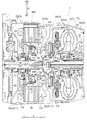
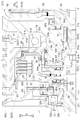
- FIG. 3 is a partially enlarged view of FIG. 2.
- the “axial direction L”, “radial direction R”, and “circumferential direction” are the rotational axis of the rotating electrical machine MG (the axial center shown in FIG. 2).
- X is defined as a standard.
- “Axis first direction L1” represents a direction (right side in FIG. 2) from the rotary electric machine MG toward the torque converter TC along the axis direction L
- “Axis second direction L2” represents the axis first direction. This represents the direction opposite to L1 (left side in FIG. 2).
- the “inner diameter direction R1” represents a direction toward the inner side of the radial direction R
- the “outer diameter direction R2” represents a direction toward the outer side of the radial direction R.
- the direction about each member represents the direction in the state in which the said member was assembled
- FIG. Further, terms relating to the direction, position, etc. of each member are used as a concept including a state having a difference due to an allowable error in manufacturing.
- the vehicle drive device 1 includes a rotating electrical machine MG, a torque converter TC, and a case 3 (see FIG. 2) that houses the rotating electrical machine MG and the torque converter TC.
- the torque converter TC is drivingly connected to the rotating electrical machine MG, and specifically, provided in a power transmission path between the rotating electrical machine MG and the output shaft O.
- the output shaft O is drivingly connected to the wheels W via the output differential gear device DF, and the rotation and torque transmitted to the output shaft O are transmitted to the left and right wheels via the output differential gear device DF. It is distributed to W and transmitted.
- the vehicle drive device 1 can drive the vehicle by transmitting the torque of the rotating electrical machine MG to the wheels W.
- the torque converter TC corresponds to a “fluid coupling” according to the present invention.
- the vehicle drive device 1 is configured such that the vehicle can travel by transmitting the torque of the internal combustion engine E to the wheels W. That is, the vehicle drive device 1 includes an input shaft I that is drivingly connected to the internal combustion engine E. As shown in FIG. 1, in the power transmission path that connects the internal combustion engine E and the wheels W, as shown in FIG. In order from the side, an input shaft I, a rotating electrical machine MG, a torque converter TC, and an output shaft O are provided.
- the vehicle drive device 1 is a hybrid vehicle drive device (hybrid drive device) that uses one or both of the internal combustion engine E and the rotating electrical machine MG as a drive power source of the vehicle, specifically, In other words, it is configured as a so-called one-motor parallel type hybrid drive device.
- the input shaft I corresponds to the “input member” in the present invention.
- the internal combustion engine E is a prime mover that is driven by the combustion of fuel inside the engine to extract power, and for example, a gasoline engine or a diesel engine can be used.
- the input shaft I is drivingly connected to the output shaft (crankshaft or the like) of the internal combustion engine E via a damper 16 (see FIG. 2, omitted in FIG. 1).
- the input shaft I may be driven and connected to the output shaft of the internal combustion engine E without using the damper 16.
- a first clutch C ⁇ b> 1 that functions as an internal combustion engine disconnecting clutch that disconnects the internal combustion engine E from the wheel W between the input shaft I and the rotating electrical machine MG in the power transmission path.
- a transmission mechanism TM is disposed between the torque converter TC and the output shaft O in the power transmission path.
- the speed change mechanism TM is composed of a mechanism (for example, an automatic stepped speed change mechanism) whose speed ratio can be changed stepwise or steplessly, and changes the rotational speed of the intermediate shaft M (speed change input shaft) at a predetermined speed ratio. Then, it is transmitted to the output shaft O (transmission output shaft).
- the first clutch C1 corresponds to the “engagement device” in the present invention.
- the input shaft I, the first clutch C1, the rotating electrical machine MG, the torque converter TC, the speed change mechanism TM, and the output shaft O are all disposed on the axis X (see FIG. 2).
- the vehicle drive device 1 according to the embodiment has a uniaxial configuration suitable for mounting on an FR (Front-Engine-Rear-Drive) type vehicle.
- the case 3 includes a first support wall portion 31, a second support wall portion 32, a third support wall portion 33, and a peripheral wall portion 34.
- the peripheral wall 34 is formed in a substantially cylindrical shape that covers the outer periphery of the rotating electrical machine MG, the first clutch C1, the torque converter TC, and the like.
- the second support wall portion 32, the first support wall portion 31, and the third support wall portion 33 are formed so as to divide the inner space of the case formed on the radially inner side R1 side of the peripheral wall portion 34 in the axial direction L. These are arranged in the order described from the second axial direction L2 side.
- the first support wall portion 31 corresponds to the “support wall portion” in the present invention.
- the rotating electrical machine MG and the first clutch C ⁇ b> 1 are accommodated in the space between the first support wall portion 31 and the second support wall portion 32 in the case 3.
- the space between the first support wall portion 31 and the second support wall portion 32 has a length in the axial direction L that is greater in the radially inner direction R1 side than in the radially outer direction R2 side. It is formed in a short shape.
- the torque converter TC is accommodated in the space between the first support wall portion 31 and the third support wall portion 33 in the case 3.
- the damper 16 is accommodated in the space in the axial second direction L2 side from the second support wall portion 32 in the case 3.
- the first support wall 31 is formed to extend in the radial direction R between the rotating electrical machine MG and the torque converter TC in the axial direction L.
- the first support wall portion 31 is a disk-shaped wall portion that extends in the circumferential direction in addition to the radial direction R, and penetrates in the axial direction L in the central portion of the radial direction R.
- a hole (hereinafter referred to as “first through hole”) is formed.
- the first support wall portion 31 has a shape that is offset in the axial direction L so that the portion on the radial inner side R1 side as a whole is positioned closer to the second axial direction L2 side than the portion on the radial outer side R2 side. ing.
- the first support wall 31 includes a first cylindrical protrusion 40 that protrudes toward the second axial direction L2.
- the first cylindrical protruding portion 40 is disposed coaxially with the axis X at the central portion of the first support wall portion 31 in the radial direction R.
- the peripheral surface 40b (see FIG. 3) forms the outer edge portion of the first through hole. That is, the 1st cylindrical protrusion part 40 is made into the thick part (boss
- the 1st cylindrical protrusion part 40 is corresponded to the "cylindrical protrusion part" in this invention.
- the first cylindrical projecting portion 40 is disposed on the radial inner side R1 side from the rotor member 21 described later and at a position having a portion overlapping the rotor member 21 when viewed in the radial direction R.
- “having overlapping portions when viewed in a predetermined direction” means that the viewpoint is moved in each direction perpendicular to the line-of-sight direction with the predetermined direction as the line-of-sight direction. In this case, it means that a viewpoint where two members appear to overlap each other exists in at least a part of the region.
- the tip end portion 40a on the second axial direction L2 side of the first cylindrical protrusion 40 overlaps with the central region in the axial direction L of the rotating electrical machine MG in the radial direction R.
- the proximal end portion of the first cylindrical protrusion 40 on the axial first direction L1 side is disposed at a position in the axial direction L, and the end portion on the axial first direction L1 side of the rotor member 21 is closer to the axial first direction L1 side.
- a part of the power transmission member T which will be described later, is disposed on the inner radial direction R1 side of the first cylindrical protrusion 40, that is, inside the first through hole.
- a stepped portion 40d having a surface (in this example, a cylindrical surface) facing the radially inward direction R1 is formed on the side surface portion of the first cylindrical protrusion 40 on the first axial direction L1 side.
- the second support wall portion 32 extends in the radial direction R on the second axial direction L2 side (in this example, between the rotary electric machine MG and the damper 16 in the axial direction L) from the rotary electric machine MG. It is formed as follows.
- the second support wall portion 32 is a disc-shaped wall portion extending in the circumferential direction in addition to the radial direction R, and a through-hole (hereinafter referred to as an axial direction L) is formed in the central portion in the radial direction R. , Referred to as “second through hole”).
- the input shaft I is inserted through the second through hole.
- the second support wall portion 32 has a shape that is offset in the axial direction L so that the portion on the inner radial direction R1 side is positioned on the first axial direction L1 side relative to the portion on the outer radial direction R2 side as a whole. ing. As shown in FIG. 3, the inner peripheral surface 32b of the portion on the radial inner direction R1 side of the second support wall portion 32 that forms the outer edge portion of the second through hole is a surface facing the first axial direction L1 side ( In this example, an inner circumferential step portion 32d having an annular surface is formed.
- the portion on the axial first direction L1 side from the inner circumferential step 32d is a large diameter portion, and the portion on the second axial direction L2 side from the inner circumferential step 32d is a small diameter portion. It is said that.
- the oil pump 9 is provided on the third support wall 33, and a pump drive shaft 67 for driving the oil pump 9 is drivingly connected so as to rotate integrally with a pump impeller 61 (to be described later) of the torque converter TC. .
- a pump impeller 61 to be described later
- the pump drive shaft 67 is supported in the radial direction R so as to be rotatable with respect to the third support wall 33 via a ninth bearing 79 (in this example, a needle bearing) and a pump case.
- the rotating electrical machine MG includes a stator St fixed to the case 3 and a rotor member 21 as shown in FIG.
- the stator St includes coil end portions Ce on both sides in the axial direction L.
- the rotor member 21 includes a rotor Ro and a rotor support member 22 that extends from the rotor Ro toward the radially inward direction R1 and supports the rotor Ro.
- the rotor Ro is disposed on the inner radial direction R1 side of the stator St, and is supported rotatably with respect to the case 3 via a rotor support member 22 that rotates integrally with the rotor Ro.
- the rotor Ro corresponds to the “rotor body” in the present invention.
- the radially extending portion 26 is formed integrally with the rotor holding portion 25, and extends from the portion on the axial first direction L1 side toward the radially inward direction R1 side with respect to the central portion in the axial direction L of the rotor holding portion 25. Is formed.
- the radially extending portion 26 is an annular plate-like portion that extends in the circumferential direction in addition to the radial direction R. In the present embodiment, the radially extending portion 26 extends in parallel to the radial direction R, and the end portion on the radial inner direction R1 side is on the radially outer side R2 side with respect to the outer peripheral surface of the first cylindrical protruding portion 40. It is formed so that it may be located in.
- a first sleeve member 94 is disposed in the gap in the radial direction R between the outer peripheral surface of the first cylindrical protrusion 40.
- the first sleeve member 94 is provided to restrict oil from flowing in the axial direction L through the gap.
- the radially extending portion 26 includes a first axial projecting portion 23 that is a cylindrical projecting portion projecting toward the first axial direction L1 side.
- the first axial protrusion 23 is disposed coaxially with the axis X, and in the present embodiment, the first axial protrusion 23 is integrated with the radial extension 26 at the end of the radial extension 26 on the radial inner side R1 side. Is formed.
- the first axial protruding portion 23 is a second cylindrical shape when viewed in the radial direction R between the first cylindrical protruding portion 40 and the second cylindrical protruding portion 41 in the radial direction R. It is arranged at a position having a portion overlapping with the protruding portion 41.
- the first axial protrusion 23 corresponds to an “axial protrusion” in the present invention.
- the radial direction extension part 26 is provided with the 2nd axial direction protrusion part 24 which is a cylindrical protrusion part which protrudes toward the axial 2nd direction L2 side.
- the second axially projecting portion 24 is disposed coaxially with the axis X, and in the present embodiment, the second axially projecting portion 24 is integrated with the radially extending portion 26 at the end portion on the radially inward direction R1 side of the radially extending portion 26. Is formed.
- the distal end portion 24a on the second axial direction L2 side of the second axial projecting portion 24 is positioned on the second axial direction L2 side with respect to the distal end portion 40a of the first cylindrical projecting portion 40.
- a plate-like member 27 is attached to the rotor support member 22.
- the plate member 27 is an annular plate member that extends in the circumferential direction in addition to the radial direction R. And in this embodiment, as shown in FIG. 3, the outer peripheral surface of the plate-shaped member 27 with respect to the inner peripheral surface of the part of the rotor holding
- an inner peripheral step portion 25d having a surface (annular surface in this example) facing the second axial direction L2 side is formed.
- the portion in the second axial direction L2 side from the inner circumferential step 25d is a large diameter portion
- the portion in the first axial direction L1 side from the inner circumferential step 25d is a small diameter portion. It is said that.
- a snap ring 93 is locked to a portion of the inner peripheral surface of the rotor holding portion 25 opposite to the inner peripheral stepped portion 25 d in the axial direction L with respect to the outer peripheral surface of the plate-like member 27.
- the plate-like member 27 attached to the rotor holding portion 25 is in a state in which movement in the axial direction L relative to the rotor holding portion 25 is allowed to some extent, and movement toward the first axial direction L1 side is an inner circumferential step portion. The movement toward the second axial direction L2 side is restricted by the snap ring 93.
- FIG. 3 in the state where the plate-like member 27 is in contact with the surface of the inner circumferential stepped portion 25 d facing the second axial direction L ⁇ b> 2, the axial member L is interposed between the plate-like member 27 and the snap ring 93.
- the state which has a clearance gap (4th clearance gap D4) is shown.
- the plate-like member 27 has a shape that is offset in the axial direction L such that the portion on the radial inner side R1 side is positioned on the second axial direction L2 side as compared with the portion on the radial outer side R2 side as a whole. have.
- a thick portion 28 having a larger thickness in the axial direction L than the portion on the radially outer direction R2 side is formed at the end portion on the radially inner direction R1 side of the plate-like member 27.
- the outer peripheral surface 28c is formed with an outer peripheral step portion 28d having a surface (annular surface in this example) facing the second axial direction L2.
- the portion on the axial first direction L1 side from the outer circumferential step portion 28d is a large diameter portion
- the portion on the axial second direction L2 side from the outer circumferential step portion 28d is a small diameter portion.
- the outer peripheral step portion 28d of the plate-like member 27 is located on the first axial direction L1 side with respect to the inner peripheral step portion 32d of the second support wall portion 32.
- the plate member 27 is a space defined on both sides in the radial direction R by the outer peripheral surface 28 c of the thick portion 28 of the plate member 27 and the inner peripheral surface 32 b of the second support wall portion 32.
- a space defined on both sides in the axial direction L by the portion 28d and the inner peripheral step portion 32d of the second support wall portion 32 is a bearing arrangement space for arranging a seventh bearing 77 described later.
- the first clutch C ⁇ b> 1 is disposed between the radially extending portion 26 in the axial direction L and the plate-like member 27. Further, the first clutch C1 is disposed on the radial inner side R1 side from the rotor Ro and at a position having a portion overlapping with the rotor Ro when viewed in the radial direction R. In the present embodiment, the first clutch C1 is disposed at a position in the axial direction L that overlaps with the central region of the rotor Ro in the axial direction L when viewed in the radial direction R.
- the first clutch C1 includes a clutch hub 51, a friction member 53, and a piston 54, and is configured as a wet multi-plate clutch mechanism.
- the rotor holding portion 25 of the rotor support member 22 functions as a clutch drum.
- the first clutch C1 has a pair of input side friction member and output side friction member as the friction member 53, and the input side friction member is supported from the radially inner side R1 side by the outer peripheral portion of the clutch hub 51, and outputs.
- the side friction member is supported from the radially outward direction R2 side by the inner peripheral portion of the rotor holding portion 25.
- a portion of the clutch hub 51 excluding the holding portion of the friction member 53 is an annular plate-like portion extending in the radial direction R and the circumferential direction, and an end portion on the radial inward direction R1 side is connected to the flange portion Ia of the input shaft I ( In this example, it is joined by welding).
- the oil discharged from the oil pump 9 is separated into the space defined on both sides in the axial direction L by the radially extending portion 26 and the plate-like member 27 and partitioned on the radially outward direction R2 side by the rotor holding portion 25.
- the friction member 53 is cooled by the oil.
- the torque converter TC is disposed coaxially with the rotating electrical machine MG on the first axial direction L1 side with respect to the rotating electrical machine MG.
- the torque converter TC is disposed between the first support wall portion 31 and the third support wall portion 33 in the axial direction L.
- the torque converter TC includes a joint input member 2 that is drivingly connected to the rotor member 21 of the rotating electrical machine MG, and a joint output member 4 that is drivingly connected to the wheels W.
- the torque converter TC includes a pump impeller 61, a turbine runner 62, a second clutch C2 as a lock-up clutch, and a cover portion 63 that accommodates these.
- the cover part 63 is connected so as to rotate integrally with the pump impeller 61 disposed inside.
- the pump drive shaft 67 is connected to the cover portion 63 so as to rotate integrally.
- the joint input member 2 is configured by the pump impeller 61, the cover portion 63, and the pump drive shaft 67.
- the joint input member 2 is drivingly connected to the rotor member 21 via the connecting member 10.
- the joint input member 2 and the rotor member 21 are drive-coupled in a state in which they can be relatively moved in the axial direction.
- the joint output member 4 is constituted by a turbine runner 62, and the turbine runner 62 is drivingly connected to the intermediate shaft M.
- the joint output member 4 is drivingly connected to the wheel W via the intermediate shaft M, the speed change mechanism TM, the output shaft O, and the output differential gear device DF, as shown in FIG.
- the turbine runner 62 and the intermediate shaft M are driven and connected by spline fitting so that they can move relative to each other in the axial direction L and rotate together with a certain amount of backlash (play) in the circumferential direction.
- the cover part 63 includes a cover radial direction extension part 65 extending in the radial direction R on the first axial direction L1 side with respect to the first support wall part 31, and a cover radial direction extension part. 65 (in this example, a cylindrical cover cylindrical protruding portion 64 that protrudes in the axial second direction L2 side from the radial inner side R1 side end of the cover radial direction extending portion 65).
- the cover radial extending portion 65 is formed so as to extend from the end portion on the first axial direction L1 side of the cover cylindrical projecting portion 64 toward the radially outward direction R2, and in this example, in addition to the radial direction R, the circumferential direction It is also an annular plate-like portion that extends.
- a thick portion 66 having a larger thickness in the axial direction L than the portion on the outer radial direction R2 side is formed in the portion on the cover cylindrical projecting portion 64 side in the cover radial direction extending portion 65.
- the cover cylindrical protrusion 64 is arranged coaxially with the axis X, and extends in the axial direction L on the outer peripheral surface of the cover cylindrical protrusion 64 (only the base end side portion in this example).
- First spline teeth 91 are formed. Further, a fastening hole 64e for fastening and fastening the fastening member 90 is formed in the radially inward direction R1 side portion of the cover cylindrical protrusion 64. In the present embodiment, the cover radial extending portion 65 and the cover cylindrical projecting portion 64 are integrally formed.
- the cover radial direction extending portion 65 is disposed away from the first support wall portion 31 so that a gap in the axial direction L is formed between the cover radial direction extension portion 65 and the first support wall portion 31. ing. A gap in the axial direction L between the side surface portion on the axial second direction L2 side of the cover radial direction extending portion 65 and the side surface portion on the axial first direction L1 side of the first support wall portion 31 will be described later.
- a bearing arrangement space for arranging the first bearing 71 is provided. Specifically, as described above, the stepped portion 40d is formed on the side surface portion of the first cylindrical protruding portion 40 of the first support wall portion 31 on the first axial direction L1 side.
- a surface in this example, a cylindrical surface facing the radial outer direction R2 ) Having a step portion 66d.
- the step portion 66d is formed in the thick portion 66 provided in the cover radial direction extending portion 65.
- first support wall portion 31 specifically, the first cylindrical protruding portion 40
- cover radial direction extending portion 65 specifically, a thick portion 66.
- the power transmission member T is configured such that the rotor member 21 and the joint input member 2 are coupled so as to rotate in conjunction with each other.
- “in conjunction with” means a state in which the ratio of the rotational speeds of the rotor member 21 and the joint input member 2 is uniquely determined.
- the rotor member 21 and the joint input member 2 are coupled so as to rotate integrally, thereby configuring the power transmission member T.
- the rotor member 21 and the joint input member 2 are connected via a connecting member 10 described below. That is, in the present embodiment, the power transmission member T includes the rotor member 21, the joint input member 2, and the connecting member 10.
- the connecting member 10 extends in the axial direction L through the radially inward direction R ⁇ b> 1 side of the first cylindrical projecting portion 40, and has a second axis from the distal end portion 40 a of the first cylindrical projecting portion 40. In the direction L2 side, it is formed so that it may extend from the said 1st cylindrical protrusion part 40 to the radial direction R2 side.
- the connecting member 10 includes the connecting radial extending portion 12 extending in the radial direction R on the second axial direction L2 side with respect to the first support wall portion 31, and the connecting radial extending portion 12 from the connecting radial extending portion 12. And a cylindrical connecting cylindrical protruding portion 11 protruding toward the one direction L1.
- connection cylindrical protrusion part 11 is arrange
- FIG. It is formed so as to extend from the end on the side toward the radially outward direction R2.
- the connecting radial extending portion 12 is an annular plate-like portion extending in the circumferential direction in addition to the radial direction R.
- the connecting radial direction extending portion 12 and the connecting cylindrical protruding portion 11 are integrally formed in this embodiment.
- the connecting member 10 constitutes a “connecting portion” in the present invention.
- the cover part 63 (joint input member 2) and the connecting member 10 are connected to each other so as to rotate integrally. And by the cover cylindrical projection part 64 and the connection cylindrical projection part 11 which were mutually connected by spline fitting in this way, it extends in the axial direction L through the radially inner direction R1 side of the first support wall part 31. An axially extending portion 5 of the power transmission member T is formed.
- connection between the cover cylindrical protrusion 64 and the connection cylindrical protrusion 11 is a spline connection by the spline teeth 91 and 92 extending in the axial direction L, it is formed integrally with the cover cylindrical protrusion 64.
- the relative movement in the axial direction L between the cover radial extending portion 65 and the connecting radial extending portion 12 formed integrally with the connecting cylindrical protruding portion 11 is not restricted by the spline connection.
- both the movement of the joint input member 2 toward the first axial direction L1 side and the movement of the joint input member 2 toward the second axial direction L2 side are performed by the first support wall portion 31.
- a configuration is adopted in which the existing portion 12 is connected in a state where relative movement in the axial direction L via the axially extending portion 5 is restricted. Such a configuration is realized by providing a movement restricting mechanism MR described below.
- the movement restricting mechanism MR is a mechanism that restricts the relative movement in the axial direction L between the cover tubular projecting portion 64 and the connecting tubular projecting portion 11.
- the end surface (tip portion 11a) on the first axial direction L1 side of the connecting cylindrical protruding portion 11 is a cover radial direction extending portion 65 (thick portion 66 in this example).
- the surface of the fastening member 90 fastened and fixed to the cover tubular projecting portion 64 facing the first axial direction L1 side contacts the surface of the connecting tubular projecting portion 11 facing the second axial direction L2 side.
- a movement restriction mechanism MR is configured.
- an inner circumferential step portion 11d having a surface (annular surface in this example) facing the second axial direction L2 side is formed on the inner circumferential surface of the connecting cylindrical protruding portion 11.
- the fastening member 90 projects in the radially outward direction R2 side from the outer peripheral surface of the cover tubular projecting portion 64 while being fastened and fixed to the fastening hole 64e of the cover tubular projecting portion 64.
- the movement restricting mechanism MR has an annular portion (in this example, a bolt head of a flanged bolt), and the annular portion abuts against the surface of the inner circumferential stepped portion 11d facing the second axial direction L2 side. It is configured.
- the connecting radially extending portion 12 is connected to the rotor support member 22 on the radially outward direction R2 side from the first cylindrical protruding portion 40.
- the end portion on the radially outward direction R2 side of the connecting radially extending portion 12 and the end portion (tip portion 24a) on the second axial direction L2 side of the second axial protruding portion 24 of the rotor support member 22 are provided. Are coupled (engaged) so as to rotate together in a state of being relatively movable in the axial direction L.
- connection cylindrical protrusion part 11 is arrange
- a gap in the radial direction R between the portion 40 and the inner peripheral surface 40b serves as a bearing arrangement space for arranging a sixth bearing 76 described later.
- a second sleeve member 95 is disposed in the gap on the second axial direction L2 side from the sixth bearing 76. The second sleeve member 95 is provided to restrict the oil from flowing in the axial direction L through the gap.
- the side surface portion on the axial first direction L1 side of the connecting radial direction extending portion 12 is formed at the distal end so that a gap in the axial direction L is formed between the distal end portion 40a of the first cylindrical protruding portion 40. It arrange
- a gap in the axial direction L between the side surface portion on the axial first direction L1 side of the connecting radial extending portion 12 and the tip end portion 40a of the first cylindrical projecting portion 40 arranges a second bearing 72 described later. It is a bearing arrangement space for this purpose.
- a step portion 12d having a surface (cylindrical surface in this example) facing the inner radial direction R1 is formed on the side surface portion on the first axial direction L1 side of the connecting radial extending portion 12.
- the second sleeve member 95 is disposed so as to have a portion that protrudes toward the second axial direction L2 side from the distal end portion 40a of the first cylindrical protruding portion 40.
- the bearing arrangement space for arranging the second bearing 72 divides both sides in the radial direction R by the stepped portion 12 d of the connecting radial extending portion 12 and the outer peripheral surface of the second sleeve member 95. It is supposed to be a space.
- the vehicle drive device 1 includes a fifth bearing 75 and a seventh bearing 77 as bearings for supporting the rotor member 21 in the radial direction R.
- the rotor member 21 is supported in the radial direction R on both sides in the axial direction L by the fifth bearing 75 and the seventh bearing 77.
- the fifth bearing 75 is a bearing that supports the rotor member 21 in the radial direction R while being rotatable with respect to the first support wall portion 31, and is a radial bearing that can receive a load in the radial direction R (this example). In this case, ball bearings are used.
- the seventh bearing 77 is a bearing that supports the rotor member 21 in the radial direction R while being rotatable with respect to the second support wall 32, and is a radial bearing that can receive a load in the radial direction R (this example) In this case, ball bearings are used.
- the fifth bearing 75 corresponds to the “first bearing” in the present invention.
- the seventh bearing 77 is disposed on the radial inner side R1 side from the fifth bearing 75, and specifically, a position having a portion overlapping the first cylindrical protrusion 40 when viewed in the axial direction L. Is arranged. More specifically, the seventh bearing 77 includes an inner peripheral surface 32 b of a portion of the second support wall portion 32 on the radial inward direction R 1 side and a thick portion 28 of the plate-like member 27 attached to the rotor support member 22. It arrange
- the rotor member 21 is supported on the inner peripheral surface 32 b of the second support wall portion 32 via the plate-like member 27 and the seventh bearing 77.
- the seventh bearing 77 is press-fitted (tightly fitted) to the inner peripheral surface 32b of the second support wall portion 32, and the shaft of the inner peripheral stepped portion 32d formed on the inner peripheral surface 32b.
- the second support wall 32 is fixed to the second support wall 32 in contact with the surface facing the first direction L1.
- the seventh bearing 77 is fitted to the outer peripheral surface 28c of the thick portion 28 of the plate-like member 27 in a state where the movement in the axial direction L is allowed to some extent.
- the plate-like member 27 moves slightly from the position where it abuts against the seventh bearing 77 toward the first axial direction L 1, and the shaft of the outer circumferential step portion 28 d formed on the outer circumferential surface 28 c of the thick portion 28.
- a state in which there is a gap in the axial direction L (third gap D3) between the surface facing the two directions L2 and the seventh bearing 77 is shown.
- an eighth bearing 78 (the main bearing) that supports the input shaft I in the radial direction R in a state of being rotatable with respect to the second support wall portion 32 on the radial inner side R1 side from the seventh bearing 77.
- a needle bearing is arranged.
- the eighth bearing 78 is disposed so as to be in contact with the outer peripheral surface of the input shaft I and the inner peripheral surface of the thick portion 28 of the plate-like member 27. It is supported on the inner peripheral surface 32 b of the second support wall portion 32 via the thick portion 28 and the seventh bearing 77.
- the vehicle drive device 1 includes a sixth bearing 76 and a ninth bearing 79 (see FIG. 2) as bearings for supporting the joint input member 2 in the radial direction R.
- the sixth bearing 76 and the ninth bearing 79 are supported in the radial direction R on both sides in the axial direction L.
- the sixth bearing 76 is a bearing that supports the joint input member 2 in the radial direction R while being rotatable with respect to the first support wall 31, and receives a load in the radial direction R.
- a radial bearing that can be used (in this example, a needle bearing) is used.
- the sixth bearing 76 corresponds to the “second bearing” in the present invention.
- the sixth bearing 76 is disposed on the radial inner side R1 side of the first cylindrical protruding portion 40 of the first support wall portion 31, specifically, the first cylindrical protruding portion 40 of the first cylindrical protruding portion 40. It arrange
- the joint input member 2 is coupled so as to rotate integrally, and is connected to the inside of the first cylindrical projecting portion 40 via the coupling member 10 that is fixed so as not to be relatively movable in the axial direction L by the movement restricting mechanism MR. It is supported by the peripheral surface 40b.
- the fifth bearing 75 is disposed on the radially outward direction R2 side from the first cylindrical projecting portion 40 of the first support wall portion 31, and the sixth bearing 76 is disposed on the first support wall portion 31. It arrange
- the first bearing 71 and the second bearing 72 include the joint input member 2 and the connecting member 10 that are fixed so as not to be relatively movable in the axial direction L among the members constituting the power transmission member T. It supports with respect to the 1st support wall part 31.
- the first bearing 71 and the second bearing 72 are configured not to prohibit relative movement of members disposed on both sides in the axial direction L in the direction away from each other in the axial direction L.
- the first bearing 71 is disposed at a portion where the first support wall portion 31 and the cover radial extending portion 65 are opposed to each other in the axial direction L.
- the first bearing 71 includes a side surface portion on the first axial direction L1 side of the first cylindrical projecting portion 40 provided in the first support wall portion 31, and a thick portion provided in the cover radial direction extending portion 65.
- 66 is disposed at a portion facing the side surface portion on the second axial direction L2 side.
- the facing portion is located in a space defined on both sides in the radial direction R by the stepped portion 40d of the first cylindrical protruding portion 40 and the stepped portion 66d of the thick portion 66.
- the first bearing 71 is at least one of a surface facing the radially outward direction R2 side of the stepped portion 66d of the thick portion 66 and a surface facing the radially inward direction R1 side of the stepped portion 40d of the first cylindrical protruding portion 40. Is fitted (clear fit) in a state where the movement in the axial direction L is allowed to some extent. Therefore, the first bearing 71 does not prohibit the movement of the joint input member 2 with respect to the first support wall portion 31 on the first axial direction L1 side. In FIG.
- the joint input member 2 slightly moves toward the first axial direction L1 side from the state in which the clearance (clearance) in the axial direction L is narrowed at the portion where the first bearing 71 is disposed, and the first cylinder
- the state which has the clearance gap (1st clearance gap D1) of the axial direction L between the side part by the side of the axial first direction L1 of the protruding part 40 and the 1st bearing 71 is shown.
- the second bearing 72 is disposed in a portion where the first support wall portion 31 and the connecting radial direction extending portion 12 face each other in the axial direction L.
- the second bearing 72 includes a distal end portion 40a of the first cylindrical projecting portion 40 included in the first support wall portion 31, and a side surface portion on the first axial direction L1 side of the connecting radial extending portion 12.
- the facing portion is located in a space defined on both sides in the radial direction R by the stepped portion 12 d of the connecting radial extending portion 12 and the outer peripheral surface of the second sleeve member 95.
- the second bearing 72 has an axial direction L with respect to at least one surface of the stepped portion 12d of the connecting radial direction extending portion 12 facing the inner radial direction R1 and the outer peripheral surface of the second sleeve member 95.
- the gap in the axial direction L at the portion where the second bearing 72 is disposed is packed, and the second bearing 72 is connected to the distal end portion 40 a of the first cylindrical projecting portion 40 and the connecting radial extending portion 12.
- connected both the side parts by the side of the shaft 1st direction L1 is shown.
- a third bearing 73 (in this example) that can receive a load in the axial direction L between the connecting radial extending portion 12 in the axial direction L and the flange portion Ia of the input shaft I is further provided.
- a fourth bearing capable of receiving a load in the axial direction L between the flange portion Ia of the input shaft I in the axial direction L and the thick portion 28 of the plate-like member 27. 74 (thrust bearing in this example) is arranged.
- the third bearing 73 and the fourth bearing 74 are also configured not to prohibit relative movement of members arranged on both sides in the axial direction L in the direction away from each other in the axial direction L.
- such a load that can act on the pump impeller 61 in the second axial direction L2 side is mainly received by the first bearing 71 that is a thrust bearing.
- the first bearing 71 that is a thrust bearing.
- it can suppress that a big axial load acts on the 7th bearing 77 which is a radial bearing, and compared with the case where a big axial load acts as the 7th bearing 77, a small bearing is small.
- a configuration has a sum total of gaps in the axial direction L provided between the cover radial direction extending portion 65 and the first support wall portion 31 (hereinafter referred to as “first sum S1”).
- the first total sum S1 is determined by the gap when the cover radial direction extending portion 65 is located closest to the first axial direction L1 side in the movable range of the cover radial direction extending portion 65 in the axial direction L.
- the second total sum S2 is determined by the gap when the connecting radial direction extending portion 12 is located closest to the first axial direction L1 in the movable range of the connecting radial direction extending portion 12 in the axial direction L.
- the gaps contributing to the second total sum S ⁇ b> 2 include the gap in the axial direction L at the portion where the second bearing 72 is disposed, the gap in the axial direction L at the portion where the third bearing 73 is disposed, and the arrangement of the fourth bearing 74.
- the gap in the axial direction L in the part and the gap in the axial direction L in the arrangement part of the seventh bearing 77 are included.
- the gaps at the locations where the respective bearings are arranged include gaps that exist inside the bearings and that allow relative movement in the axial direction L between members constituting the bearings.
- FIG. 3 shows that the joint input member 2 and the connecting member 10 that are connected so as not to be relatively movable in the axial direction L are the most axial first direction L1 in the movable range of the axial direction L.
- the situation located on the side is shown. For this reason, the gap in the axial direction L at the portion where the second bearing 72 is disposed is closed, and the gap (first gap D1) in the axial direction L is present at the portion where the first bearing 71 is disposed. In this case, the first total sum S1 is “D1”. Further, FIG.
- the first sum S1 is set to be smaller than the second sum S2 (D1 ⁇ D2 + D3). Therefore, even when a large load is applied to the pump impeller 61 in the second axial direction L2 side, the axial direction L existing between the connecting radial direction extending portion 12 and the second support wall portion 32 is present. Before the gap is clogged, the gap in the axial direction L existing between the cover radial direction extending portion 65 and the first support wall portion 31 is clogged, so that the load is received by the first bearing 71 and the seventh bearing It is possible to suppress a large axial load from acting on 77.
- the snap when a large load is applied to the pump impeller 61 in the second axial direction L2, the snap is locked not only on the seventh bearing 77 but also on the rotor holding portion 25.
- the first total sum S1 is set smaller (D1 ⁇ D4) than the gap (fourth gap D4) in the axial direction L between the plate-like member 27 and the snap ring 93 in the case shown in FIG.
- the rotor member 21 is disposed so as to be in contact with the fifth bearing 75, and the plate-like member 27 is located on the most axial first direction L1 side in the movable range of the plate-like member 27 in the axial direction L.
- connection member 10 may be formed integrally with the rotor support member 22 without making the connection member 10 separate from the rotor support member 22 (an independent separate member).
- the second sum S2 in the example shown in FIG. 3 is “D3”, and it is preferable to design each part so that the relationship (D1 ⁇ D3) is satisfied.
- the connecting member 10 has the connecting radial extending portion 12 extending from the first cylindrical protruding portion 40 to the radially outward direction R2 side, and the connecting member 10 and the rotor support member 22 are connected to each other.
- the configuration in which the engaging portion is located on the radially outward direction R2 side from the first cylindrical protruding portion 40 has been described as an example.
- the embodiment of the present invention is not limited to this, and the rotor support member 22 has a portion extending from the first cylindrical protrusion 40 to the radially inward direction R1, and the connecting member 10 and the rotor support member.
- the engaging part with 22 can also be set as the structure located in the radial direction R1 side rather than the 1st cylindrical protrusion part 40.
- the connection member 10 may be configured to include only the connection cylindrical protrusion 11.
- the inner peripheral step 11 d is formed on the inner peripheral surface of the connecting cylindrical protrusion 11, and the fastening member 90 is fastened and fixed to the cover cylindrical protrusion 64 in the first axial direction L 1 side.
- the case where the movement restricting mechanism MR is configured by abutting the surface facing toward the surface facing the second axial direction L2 side of the inner circumferential step portion 11d has been described as an example.
- the embodiment of the present invention is not limited to this, and the connecting cylindrical protruding portion 11 does not include the inner circumferential step portion 11d, and the surface of the fastening member 90 facing the first axial direction L1 side is the connecting cylinder.
- the movement restricting mechanism MR may be a mechanism that restricts the relative movement in the axial direction L between the cover tubular projecting portion 64 and the connecting tubular projecting portion 11 using a snap ring or the like.
- the cover 63 and the connecting member 10 are spline-fitted in a state where the inner peripheral surface of the connecting cylindrical protruding portion 11 is externally fitted to the outer peripheral surface of the cover cylindrical protruding portion 64.
- the configuration connected to each other has been described as an example.
- the embodiment of the present invention is not limited to this, and the cover cylindrical protrusion 64 has spline teeth on the inner peripheral surface, and the connecting cylindrical protrusion 11 has spline teeth on the outer peripheral surface,
- the cover 63 and the connecting member 10 may be connected to each other by spline fitting in a state in which the inner peripheral surface of the cover cylindrical protruding portion 64 is externally fitted to the outer peripheral surface of the connecting cylindrical protruding portion 11. it can.
- the fifth bearing 75 is disposed on the radially outward direction R2 side of the first cylindrical protruding portion 40
- the sixth bearing 76 is the radially inward direction of the first cylindrical protruding portion 40.
- the configuration disposed on the R1 side has been described as an example.
- the embodiment of the present invention is not limited to this, and the fifth bearing 75 and the sixth bearing 76 are arranged on the same side in the radial direction R with respect to the first cylindrical protrusion 40. It can also be.
- the configuration in which the first clutch C1 is disposed at a position having a portion overlapping the fifth bearing 75 when viewed in the axial direction L is described as an example.
- the embodiment of the present invention is not limited to this, and, for example, the fifth bearing 75 so that the first clutch C1 does not have a portion overlapping the fifth bearing 75 when viewed in the axial direction L. It can also be set as the structure arrange
- the first clutch C1 is disposed at a position that is closer to the inner diameter direction R1 than the rotor Ro and has a portion that overlaps the rotor Ro when viewed in the radial direction R.
- the embodiment of the present invention is not limited to this, and the first axial direction L1 from the rotor Ro is such that the first clutch C1 does not have a portion overlapping the rotor Ro when viewed in the radial direction R. It can also be set as the structure arrange
- the sixth bearing 76 has been described as an example of a configuration in which the sixth bearing 76 is disposed at a position having a portion overlapping the fifth bearing 75 when viewed in the radial direction R.
- the fifth bearing 75 may be arranged at a different position in the axial direction L so as not to have a portion overlapping with the fifth bearing 75 when viewed in the radial direction R.
- the end of the connecting radial extending portion 12 on the outer radial direction R2 side is an external tooth engagement in which a plurality of engaging pieces protruding in the outer radial direction R2 side are arranged in the circumferential direction.
- the distal end portion 24a of the second axial projecting portion 24 has a through-hole in the radial direction R having a width in the circumferential direction and a length in the axial direction L in the circumferential direction.
- a configuration in which a plurality of (the same number as that of the engagement pieces) cylindrically arranged engaging portions are described as an example. However, the embodiment of the present invention is not limited to this.
- the distal end portion 24a of the second axial projecting portion 24 is configured as an internal tooth engaging portion in which a plurality of engaging pieces projecting in the radially inward direction R1 side are dispersed in the circumferential direction instead of the through hole. It can be.
- the second axial projecting portion 24 has an annular main body portion continuous over the entire circumference also at the distal end portion 24a.
- the outer peripheral surface 23c of the first axial protrusion 23 of the rotor support member 22 is a supported portion supported by the fifth bearing 75 with respect to the first support wall 31.
- the fifth bearing 75 is configured such that the inner peripheral surface 23b of the first axial projecting portion 23 and the outer peripheral surface of the first support wall portion 31 (for example, the first The structure arrange
- the structure which is a supported part It can also be set as the structure which is a supported part. Further, a portion of the rotor support member 22 other than the first axial projection 23 (for example, the inner peripheral surface of the second axial projection 24) is supported by the bearing with respect to the first support wall 31. It can also be set as the structure which is a support part. In this case, the rotor support member 22 may be configured not to include the first axial protrusion 23.
- the configuration in which the first axial protruding portion 23 of the rotor support member 22 is formed at the end portion on the radially inward direction R1 side of the radially extending portion 26 has been described as an example.
- the embodiment of the present invention is not limited to this, and the first axial protruding portion 23 is an intermediate portion in the radial direction R of the radially extending portion 26 (for example, from the second cylindrical protruding portion 41). It can also be set as the structure currently formed in the radial direction R2 side.
- the first bearing 71 and the second bearing 72 have been described as an example in which the power transmission member T is supported with respect to the first cylindrical protrusion 40 of the first support wall 31.
- the embodiment of the present invention is not limited to this, and at least one of the first bearing 71 and the second bearing 72 is a portion where the thickness in the axial direction L of the first support wall portion 31 is uniform.
- the power transmission member T may be supported.
- the first support wall portion 31 may be configured not to include the first cylindrical protruding portion 40.
- the vehicle drive device 1 includes the input shaft I that is drivingly connected to the internal combustion engine E and the first clutch C1 has been described as an example.
- the embodiment of the present invention is not limited to this, and the vehicle drive device 1 may be configured not to include the input shaft I or the first clutch C1.
- the present invention includes a rotating electrical machine, a fluid coupling disposed coaxially with the rotating electrical machine, and a case that houses the rotating electrical machine and the fluid coupling, and the fluid coupling is drivingly connected to a rotor member of the rotating electrical machine. It can utilize suitably for a vehicle drive device provided with an input member and a joint output member drivingly connected with a wheel.
Landscapes
- Engineering & Computer Science (AREA)
- Mechanical Engineering (AREA)
- Chemical & Material Sciences (AREA)
- Combustion & Propulsion (AREA)
- Transportation (AREA)
- General Engineering & Computer Science (AREA)
- Hybrid Electric Vehicles (AREA)
- Arrangement And Driving Of Transmission Devices (AREA)
- Electric Propulsion And Braking For Vehicles (AREA)
- Shafts, Cranks, Connecting Bars, And Related Bearings (AREA)
Abstract
Priority Applications (3)
| Application Number | Priority Date | Filing Date | Title |
|---|---|---|---|
| DE112012003191.1T DE112012003191B4 (de) | 2011-11-04 | 2012-10-31 | Fahrzeugantriebsvorrichtung |
| US14/240,310 US9068638B2 (en) | 2011-11-04 | 2012-10-31 | Vehicle drive device |
| CN201280042325.5A CN103764422B (zh) | 2011-11-04 | 2012-10-31 | 车辆用驱动装置 |
Applications Claiming Priority (2)
| Application Number | Priority Date | Filing Date | Title |
|---|---|---|---|
| JP2011242701A JP5425163B2 (ja) | 2011-11-04 | 2011-11-04 | 車両用駆動装置 |
| JP2011-242701 | 2011-11-04 |
Publications (1)
| Publication Number | Publication Date |
|---|---|
| WO2013065748A1 true WO2013065748A1 (fr) | 2013-05-10 |
Family
ID=48192090
Family Applications (1)
| Application Number | Title | Priority Date | Filing Date |
|---|---|---|---|
| PCT/JP2012/078189 Ceased WO2013065748A1 (fr) | 2011-11-04 | 2012-10-31 | Dispositif de propulsion de véhicule |
Country Status (5)
| Country | Link |
|---|---|
| US (1) | US9068638B2 (fr) |
| JP (1) | JP5425163B2 (fr) |
| CN (1) | CN103764422B (fr) |
| DE (1) | DE112012003191B4 (fr) |
| WO (1) | WO2013065748A1 (fr) |
Cited By (1)
| Publication number | Priority date | Publication date | Assignee | Title |
|---|---|---|---|---|
| US11035449B2 (en) * | 2016-12-09 | 2021-06-15 | Daimler Ag | Torque converter device, in particular for a drive train of a motor vehicle |
Families Citing this family (19)
| Publication number | Priority date | Publication date | Assignee | Title |
|---|---|---|---|---|
| JP6215741B2 (ja) * | 2014-03-14 | 2017-10-18 | トヨタ自動車株式会社 | ハイブリッド車両 |
| JP6027044B2 (ja) * | 2014-03-14 | 2016-11-16 | トヨタ自動車株式会社 | 車両用駆動装置とその組付方法 |
| JP2017520449A (ja) * | 2014-06-11 | 2017-07-27 | シェフラー テクノロジーズ アー・ゲー ウント コー. カー・ゲーSchaeffler Technologies AG & Co. KG | ハイブリッドモジュール用のモジュール式のハウジング |
| JP2016033003A (ja) * | 2014-07-29 | 2016-03-10 | アイシン・エィ・ダブリュ株式会社 | ハイブリッド駆動装置 |
| CN108349368B (zh) † | 2015-11-25 | 2021-10-26 | 舍弗勒技术股份两合公司 | 带分离离合器和主离合器以及布置在它们之间的操纵系统的混合动力模块 |
| JP6531133B2 (ja) * | 2017-04-27 | 2019-06-12 | 本田技研工業株式会社 | ハイブリッド車両の駆動装置 |
| DE102017217209A1 (de) * | 2017-09-27 | 2019-03-28 | Zf Friedrichshafen Ag | Hybridantriebsstranganordnung sowie Verfahren zur Montage einer Elektromotoranordnung |
| US10965182B2 (en) * | 2018-03-01 | 2021-03-30 | Schaeffler Technologies AG & Co. KG | Hybrid module including axial retention housing for bearing |
| JP7126365B2 (ja) * | 2018-03-28 | 2022-08-26 | 株式会社エクセディ | 車両用の駆動装置 |
| JP7043312B2 (ja) | 2018-03-28 | 2022-03-29 | 株式会社エクセディ | 車両用の駆動装置 |
| DE102018205460A1 (de) * | 2018-04-11 | 2019-10-17 | Zf Friedrichshafen Ag | Hybridantriebsmodul für ein Kraftfahrzeug |
| JP2019196057A (ja) * | 2018-05-08 | 2019-11-14 | 本田技研工業株式会社 | 車両駆動装置 |
| DE102018211374B4 (de) * | 2018-07-10 | 2025-09-11 | Zf Friedrichshafen Ag | Rotorträger für eine elektrische Maschine |
| US10293674B1 (en) | 2018-11-20 | 2019-05-21 | Gm Global Technology Operations Llc. | Engine disconnect clutches having torque converter feed-through activation for vehicle powertrains |
| EP3886298B1 (fr) * | 2019-01-09 | 2024-03-06 | Aisin Corporation | Dispositif d'entraînement de véhicule |
| CN113329899B (zh) * | 2019-01-09 | 2024-10-29 | 株式会社爱信 | 混合驱动装置 |
| US11114917B1 (en) * | 2020-02-26 | 2021-09-07 | Schaeffler Technologies AG & Co. KG | Electric motor rotor for hybrid module |
| WO2022030396A1 (fr) * | 2020-08-03 | 2022-02-10 | 株式会社アイシン | Dispositif de propulsion de véhicule |
| JP2022028584A (ja) * | 2020-08-03 | 2022-02-16 | 株式会社アイシン | 車両用駆動装置 |
Citations (5)
| Publication number | Priority date | Publication date | Assignee | Title |
|---|---|---|---|---|
| JP2006137406A (ja) * | 2004-10-15 | 2006-06-01 | Aisin Seiki Co Ltd | 複数の駆動源を備えた車両用駆動装置 |
| US20060289209A1 (en) * | 2005-06-22 | 2006-12-28 | Zf Friedrichshafen Ag | Electromotive drive module |
| WO2008065803A1 (fr) * | 2006-11-27 | 2008-06-05 | Aisin Aw Co., Ltd. | Dispositif d'entraînement hybride |
| EP2287487A1 (fr) * | 2009-08-21 | 2011-02-23 | Volkswagen Aktiengesellschaft | Module d'entraînement pour un véhicule automobile |
| JP2011106629A (ja) * | 2009-11-19 | 2011-06-02 | Aisin Aw Co Ltd | 車両用駆動装置 |
Family Cites Families (13)
| Publication number | Priority date | Publication date | Assignee | Title |
|---|---|---|---|---|
| JPH09215270A (ja) | 1996-02-02 | 1997-08-15 | Honda Motor Co Ltd | 電動機の冷却構造 |
| DE19747964A1 (de) | 1997-10-30 | 1999-05-12 | Bayerische Motoren Werke Ag | Anbindung für einen Drehmomentwandler |
| JP2003063263A (ja) * | 2001-08-24 | 2003-03-05 | Honda Motor Co Ltd | ハイブリッド車両の動力伝達装置 |
| JP4568496B2 (ja) * | 2003-12-18 | 2010-10-27 | 富士重工業株式会社 | トルクコンバータ |
| US20080099258A1 (en) * | 2006-10-26 | 2008-05-01 | Berhan Michael T | Vented sealed housing assembly for vehicle powertrain |
| WO2009128288A1 (fr) * | 2008-04-14 | 2009-10-22 | 本田技研工業株式会社 | Unité d'entraînement de véhicule hybride |
| US8322504B2 (en) * | 2008-08-14 | 2012-12-04 | Schaeffler Technologies AG & Co. KG | Combined power transmission, drive unit and drive train for a hybrid system |
| JP5131153B2 (ja) * | 2008-10-28 | 2013-01-30 | アイシン・エィ・ダブリュ株式会社 | 車両用駆動装置 |
| JP5157823B2 (ja) * | 2008-10-28 | 2013-03-06 | アイシン・エィ・ダブリュ株式会社 | 車両用駆動装置 |
| JP4941778B2 (ja) * | 2008-10-31 | 2012-05-30 | アイシン・エィ・ダブリュ株式会社 | 車両用駆動装置 |
| JP2011105188A (ja) | 2009-11-19 | 2011-06-02 | Aisin Seiki Co Ltd | ハイブリッド車両用駆動装置 |
| JP5418334B2 (ja) * | 2010-03-17 | 2014-02-19 | トヨタ自動車株式会社 | 駆動装置 |
| US9421857B2 (en) * | 2012-01-31 | 2016-08-23 | Ford Global Technologies, Llc | Modular powertrain component for hybrid electric vehicles |
-
2011
- 2011-11-04 JP JP2011242701A patent/JP5425163B2/ja active Active
-
2012
- 2012-10-31 US US14/240,310 patent/US9068638B2/en active Active
- 2012-10-31 CN CN201280042325.5A patent/CN103764422B/zh active Active
- 2012-10-31 DE DE112012003191.1T patent/DE112012003191B4/de not_active Expired - Fee Related
- 2012-10-31 WO PCT/JP2012/078189 patent/WO2013065748A1/fr not_active Ceased
Patent Citations (5)
| Publication number | Priority date | Publication date | Assignee | Title |
|---|---|---|---|---|
| JP2006137406A (ja) * | 2004-10-15 | 2006-06-01 | Aisin Seiki Co Ltd | 複数の駆動源を備えた車両用駆動装置 |
| US20060289209A1 (en) * | 2005-06-22 | 2006-12-28 | Zf Friedrichshafen Ag | Electromotive drive module |
| WO2008065803A1 (fr) * | 2006-11-27 | 2008-06-05 | Aisin Aw Co., Ltd. | Dispositif d'entraînement hybride |
| EP2287487A1 (fr) * | 2009-08-21 | 2011-02-23 | Volkswagen Aktiengesellschaft | Module d'entraînement pour un véhicule automobile |
| JP2011106629A (ja) * | 2009-11-19 | 2011-06-02 | Aisin Aw Co Ltd | 車両用駆動装置 |
Cited By (1)
| Publication number | Priority date | Publication date | Assignee | Title |
|---|---|---|---|---|
| US11035449B2 (en) * | 2016-12-09 | 2021-06-15 | Daimler Ag | Torque converter device, in particular for a drive train of a motor vehicle |
Also Published As
| Publication number | Publication date |
|---|---|
| JP5425163B2 (ja) | 2014-02-26 |
| CN103764422B (zh) | 2016-08-17 |
| DE112012003191B4 (de) | 2025-07-10 |
| JP2013095383A (ja) | 2013-05-20 |
| DE112012003191T5 (de) | 2014-04-17 |
| US9068638B2 (en) | 2015-06-30 |
| US20140230423A1 (en) | 2014-08-21 |
| CN103764422A (zh) | 2014-04-30 |
Similar Documents
| Publication | Publication Date | Title |
|---|---|---|
| JP5425163B2 (ja) | 車両用駆動装置 | |
| JP5589247B2 (ja) | 車両用駆動装置 | |
| US7975571B2 (en) | Hybrid drive device | |
| JP5255555B2 (ja) | 車両用駆動装置 | |
| JP7209742B2 (ja) | 車両用駆動装置 | |
| CN102597578B (zh) | 车辆用驱动装置 | |
| WO2011062265A1 (fr) | Dispositif d'entraînement pour véhicule | |
| CN113195276A (zh) | 车辆用驱动装置 | |
| WO2011062266A1 (fr) | Dispositif d'entraînement pour véhicule | |
| JP2009101730A (ja) | ハイブリッド駆動装置 | |
| WO2017057190A1 (fr) | Dispositif d'entraînement de véhicule | |
| JP5267871B2 (ja) | ハイブリッド車両用駆動装置 | |
| JP2012096675A (ja) | 車両用駆動装置 | |
| WO2015108147A1 (fr) | Dispositif d'entraînement de véhicule | |
| WO2017170396A1 (fr) | Dispositif de transmission d'entraînement pour véhicule | |
| JP5261461B2 (ja) | 車両用駆動装置 | |
| JP2012100454A (ja) | 車両用駆動装置 | |
| JP2015155292A (ja) | 車両用駆動装置 | |
| JP5875075B2 (ja) | 車両用駆動装置 | |
| JP2012076576A (ja) | ハイブリッド駆動装置 | |
| JP2014069757A (ja) | 車両用駆動装置 | |
| JP2016168976A (ja) | 車両用駆動装置 |
Legal Events
| Date | Code | Title | Description |
|---|---|---|---|
| 121 | Ep: the epo has been informed by wipo that ep was designated in this application |
Ref document number: 12845768 Country of ref document: EP Kind code of ref document: A1 |
|
| WWE | Wipo information: entry into national phase |
Ref document number: 14240310 Country of ref document: US |
|
| WWE | Wipo information: entry into national phase |
Ref document number: 112012003191 Country of ref document: DE Ref document number: 1120120031911 Country of ref document: DE |
|
| 122 | Ep: pct application non-entry in european phase |
Ref document number: 12845768 Country of ref document: EP Kind code of ref document: A1 |
|
| WWG | Wipo information: grant in national office |
Ref document number: 112012003191 Country of ref document: DE |