WO2013069094A1 - ハイブリッド車 - Google Patents
ハイブリッド車 Download PDFInfo
- Publication number
- WO2013069094A1 WO2013069094A1 PCT/JP2011/075720 JP2011075720W WO2013069094A1 WO 2013069094 A1 WO2013069094 A1 WO 2013069094A1 JP 2011075720 W JP2011075720 W JP 2011075720W WO 2013069094 A1 WO2013069094 A1 WO 2013069094A1
- Authority
- WO
- WIPO (PCT)
- Prior art keywords
- engine
- vehicle
- start request
- controller
- shift lever
- Prior art date
- Legal status (The legal status is an assumption and is not a legal conclusion. Google has not performed a legal analysis and makes no representation as to the accuracy of the status listed.)
- Ceased
Links
Images


Classifications
-
- B—PERFORMING OPERATIONS; TRANSPORTING
- B60—VEHICLES IN GENERAL
- B60L—PROPULSION OF ELECTRICALLY-PROPELLED VEHICLES; SUPPLYING ELECTRIC POWER FOR AUXILIARY EQUIPMENT OF ELECTRICALLY-PROPELLED VEHICLES; ELECTRODYNAMIC BRAKE SYSTEMS FOR VEHICLES IN GENERAL; MAGNETIC SUSPENSION OR LEVITATION FOR VEHICLES; MONITORING OPERATING VARIABLES OF ELECTRICALLY-PROPELLED VEHICLES; ELECTRIC SAFETY DEVICES FOR ELECTRICALLY-PROPELLED VEHICLES
- B60L53/00—Methods of charging batteries, specially adapted for electric vehicles; Charging stations or on-board charging equipment therefor; Exchange of energy storage elements in electric vehicles
- B60L53/10—Methods of charging batteries, specially adapted for electric vehicles; Charging stations or on-board charging equipment therefor; Exchange of energy storage elements in electric vehicles characterised by the energy transfer between the charging station and the vehicle
- B60L53/14—Conductive energy transfer
-
- B—PERFORMING OPERATIONS; TRANSPORTING
- B60—VEHICLES IN GENERAL
- B60K—ARRANGEMENT OR MOUNTING OF PROPULSION UNITS OR OF TRANSMISSIONS IN VEHICLES; ARRANGEMENT OR MOUNTING OF PLURAL DIVERSE PRIME-MOVERS IN VEHICLES; AUXILIARY DRIVES FOR VEHICLES; INSTRUMENTATION OR DASHBOARDS FOR VEHICLES; ARRANGEMENTS IN CONNECTION WITH COOLING, AIR INTAKE, GAS EXHAUST OR FUEL SUPPLY OF PROPULSION UNITS IN VEHICLES
- B60K6/00—Arrangement or mounting of plural diverse prime-movers for mutual or common propulsion, e.g. hybrid propulsion systems comprising electric motors and internal combustion engines
- B60K6/20—Arrangement or mounting of plural diverse prime-movers for mutual or common propulsion, e.g. hybrid propulsion systems comprising electric motors and internal combustion engines the prime-movers consisting of electric motors and internal combustion engines, e.g. HEVs
- B60K6/42—Arrangement or mounting of plural diverse prime-movers for mutual or common propulsion, e.g. hybrid propulsion systems comprising electric motors and internal combustion engines the prime-movers consisting of electric motors and internal combustion engines, e.g. HEVs characterised by the architecture of the hybrid electric vehicle
- B60K6/44—Series-parallel type
- B60K6/445—Differential gearing distribution type
-
- B—PERFORMING OPERATIONS; TRANSPORTING
- B60—VEHICLES IN GENERAL
- B60K—ARRANGEMENT OR MOUNTING OF PROPULSION UNITS OR OF TRANSMISSIONS IN VEHICLES; ARRANGEMENT OR MOUNTING OF PLURAL DIVERSE PRIME-MOVERS IN VEHICLES; AUXILIARY DRIVES FOR VEHICLES; INSTRUMENTATION OR DASHBOARDS FOR VEHICLES; ARRANGEMENTS IN CONNECTION WITH COOLING, AIR INTAKE, GAS EXHAUST OR FUEL SUPPLY OF PROPULSION UNITS IN VEHICLES
- B60K6/00—Arrangement or mounting of plural diverse prime-movers for mutual or common propulsion, e.g. hybrid propulsion systems comprising electric motors and internal combustion engines
- B60K6/20—Arrangement or mounting of plural diverse prime-movers for mutual or common propulsion, e.g. hybrid propulsion systems comprising electric motors and internal combustion engines the prime-movers consisting of electric motors and internal combustion engines, e.g. HEVs
- B60K6/42—Arrangement or mounting of plural diverse prime-movers for mutual or common propulsion, e.g. hybrid propulsion systems comprising electric motors and internal combustion engines the prime-movers consisting of electric motors and internal combustion engines, e.g. HEVs characterised by the architecture of the hybrid electric vehicle
- B60K6/48—Parallel type
-
- B—PERFORMING OPERATIONS; TRANSPORTING
- B60—VEHICLES IN GENERAL
- B60L—PROPULSION OF ELECTRICALLY-PROPELLED VEHICLES; SUPPLYING ELECTRIC POWER FOR AUXILIARY EQUIPMENT OF ELECTRICALLY-PROPELLED VEHICLES; ELECTRODYNAMIC BRAKE SYSTEMS FOR VEHICLES IN GENERAL; MAGNETIC SUSPENSION OR LEVITATION FOR VEHICLES; MONITORING OPERATING VARIABLES OF ELECTRICALLY-PROPELLED VEHICLES; ELECTRIC SAFETY DEVICES FOR ELECTRICALLY-PROPELLED VEHICLES
- B60L1/00—Supplying electric power to auxiliary equipment of vehicles
- B60L1/003—Supplying electric power to auxiliary equipment of vehicles to auxiliary motors, e.g. for pumps, compressors
-
- B—PERFORMING OPERATIONS; TRANSPORTING
- B60—VEHICLES IN GENERAL
- B60L—PROPULSION OF ELECTRICALLY-PROPELLED VEHICLES; SUPPLYING ELECTRIC POWER FOR AUXILIARY EQUIPMENT OF ELECTRICALLY-PROPELLED VEHICLES; ELECTRODYNAMIC BRAKE SYSTEMS FOR VEHICLES IN GENERAL; MAGNETIC SUSPENSION OR LEVITATION FOR VEHICLES; MONITORING OPERATING VARIABLES OF ELECTRICALLY-PROPELLED VEHICLES; ELECTRIC SAFETY DEVICES FOR ELECTRICALLY-PROPELLED VEHICLES
- B60L1/00—Supplying electric power to auxiliary equipment of vehicles
- B60L1/006—Supplying electric power to auxiliary equipment of vehicles to power outlets
-
- B—PERFORMING OPERATIONS; TRANSPORTING
- B60—VEHICLES IN GENERAL
- B60L—PROPULSION OF ELECTRICALLY-PROPELLED VEHICLES; SUPPLYING ELECTRIC POWER FOR AUXILIARY EQUIPMENT OF ELECTRICALLY-PROPELLED VEHICLES; ELECTRODYNAMIC BRAKE SYSTEMS FOR VEHICLES IN GENERAL; MAGNETIC SUSPENSION OR LEVITATION FOR VEHICLES; MONITORING OPERATING VARIABLES OF ELECTRICALLY-PROPELLED VEHICLES; ELECTRIC SAFETY DEVICES FOR ELECTRICALLY-PROPELLED VEHICLES
- B60L50/00—Electric propulsion with power supplied within the vehicle
- B60L50/10—Electric propulsion with power supplied within the vehicle using propulsion power supplied by engine-driven generators, e.g. generators driven by combustion engines
- B60L50/16—Electric propulsion with power supplied within the vehicle using propulsion power supplied by engine-driven generators, e.g. generators driven by combustion engines with provision for separate direct mechanical propulsion
-
- B—PERFORMING OPERATIONS; TRANSPORTING
- B60—VEHICLES IN GENERAL
- B60L—PROPULSION OF ELECTRICALLY-PROPELLED VEHICLES; SUPPLYING ELECTRIC POWER FOR AUXILIARY EQUIPMENT OF ELECTRICALLY-PROPELLED VEHICLES; ELECTRODYNAMIC BRAKE SYSTEMS FOR VEHICLES IN GENERAL; MAGNETIC SUSPENSION OR LEVITATION FOR VEHICLES; MONITORING OPERATING VARIABLES OF ELECTRICALLY-PROPELLED VEHICLES; ELECTRIC SAFETY DEVICES FOR ELECTRICALLY-PROPELLED VEHICLES
- B60L58/00—Methods or circuit arrangements for monitoring or controlling batteries or fuel cells, specially adapted for electric vehicles
- B60L58/10—Methods or circuit arrangements for monitoring or controlling batteries or fuel cells, specially adapted for electric vehicles for monitoring or controlling batteries
- B60L58/18—Methods or circuit arrangements for monitoring or controlling batteries or fuel cells, specially adapted for electric vehicles for monitoring or controlling batteries of two or more battery modules
- B60L58/20—Methods or circuit arrangements for monitoring or controlling batteries or fuel cells, specially adapted for electric vehicles for monitoring or controlling batteries of two or more battery modules having different nominal voltages
-
- B—PERFORMING OPERATIONS; TRANSPORTING
- B60—VEHICLES IN GENERAL
- B60W—CONJOINT CONTROL OF VEHICLE SUB-UNITS OF DIFFERENT TYPE OR DIFFERENT FUNCTION; CONTROL SYSTEMS SPECIALLY ADAPTED FOR HYBRID VEHICLES; ROAD VEHICLE DRIVE CONTROL SYSTEMS FOR PURPOSES NOT RELATED TO THE CONTROL OF A PARTICULAR SUB-UNIT
- B60W10/00—Conjoint control of vehicle sub-units of different type or different function
- B60W10/04—Conjoint control of vehicle sub-units of different type or different function including control of propulsion units
- B60W10/06—Conjoint control of vehicle sub-units of different type or different function including control of propulsion units including control of combustion engines
-
- B—PERFORMING OPERATIONS; TRANSPORTING
- B60—VEHICLES IN GENERAL
- B60W—CONJOINT CONTROL OF VEHICLE SUB-UNITS OF DIFFERENT TYPE OR DIFFERENT FUNCTION; CONTROL SYSTEMS SPECIALLY ADAPTED FOR HYBRID VEHICLES; ROAD VEHICLE DRIVE CONTROL SYSTEMS FOR PURPOSES NOT RELATED TO THE CONTROL OF A PARTICULAR SUB-UNIT
- B60W20/00—Control systems specially adapted for hybrid vehicles
-
- B—PERFORMING OPERATIONS; TRANSPORTING
- B60—VEHICLES IN GENERAL
- B60W—CONJOINT CONTROL OF VEHICLE SUB-UNITS OF DIFFERENT TYPE OR DIFFERENT FUNCTION; CONTROL SYSTEMS SPECIALLY ADAPTED FOR HYBRID VEHICLES; ROAD VEHICLE DRIVE CONTROL SYSTEMS FOR PURPOSES NOT RELATED TO THE CONTROL OF A PARTICULAR SUB-UNIT
- B60W30/00—Purposes of road vehicle drive control systems not related to the control of a particular sub-unit, e.g. of systems using conjoint control of vehicle sub-units
- B60W30/18—Propelling the vehicle
- B60W30/18009—Propelling the vehicle related to particular drive situations
- B60W30/18054—Propelling the vehicle related to particular drive situations at stand still, e.g. engine in idling state
-
- F—MECHANICAL ENGINEERING; LIGHTING; HEATING; WEAPONS; BLASTING
- F02—COMBUSTION ENGINES; HOT-GAS OR COMBUSTION-PRODUCT ENGINE PLANTS
- F02D—CONTROLLING COMBUSTION ENGINES
- F02D29/00—Controlling engines, such controlling being peculiar to the devices driven thereby, the devices being other than parts or accessories essential to engine operation, e.g. controlling of engines by signals external thereto
- F02D29/02—Controlling engines, such controlling being peculiar to the devices driven thereby, the devices being other than parts or accessories essential to engine operation, e.g. controlling of engines by signals external thereto peculiar to engines driving vehicles; peculiar to engines driving variable pitch propellers
-
- F—MECHANICAL ENGINEERING; LIGHTING; HEATING; WEAPONS; BLASTING
- F02—COMBUSTION ENGINES; HOT-GAS OR COMBUSTION-PRODUCT ENGINE PLANTS
- F02N—STARTING OF COMBUSTION ENGINES; STARTING AIDS FOR SUCH ENGINES, NOT OTHERWISE PROVIDED FOR
- F02N11/00—Starting of engines by means of electric motors
- F02N11/10—Safety devices
- F02N11/101—Safety devices for preventing engine starter actuation or engagement
-
- B—PERFORMING OPERATIONS; TRANSPORTING
- B60—VEHICLES IN GENERAL
- B60L—PROPULSION OF ELECTRICALLY-PROPELLED VEHICLES; SUPPLYING ELECTRIC POWER FOR AUXILIARY EQUIPMENT OF ELECTRICALLY-PROPELLED VEHICLES; ELECTRODYNAMIC BRAKE SYSTEMS FOR VEHICLES IN GENERAL; MAGNETIC SUSPENSION OR LEVITATION FOR VEHICLES; MONITORING OPERATING VARIABLES OF ELECTRICALLY-PROPELLED VEHICLES; ELECTRIC SAFETY DEVICES FOR ELECTRICALLY-PROPELLED VEHICLES
- B60L2210/00—Converter types
- B60L2210/10—DC to DC converters
-
- B—PERFORMING OPERATIONS; TRANSPORTING
- B60—VEHICLES IN GENERAL
- B60L—PROPULSION OF ELECTRICALLY-PROPELLED VEHICLES; SUPPLYING ELECTRIC POWER FOR AUXILIARY EQUIPMENT OF ELECTRICALLY-PROPELLED VEHICLES; ELECTRODYNAMIC BRAKE SYSTEMS FOR VEHICLES IN GENERAL; MAGNETIC SUSPENSION OR LEVITATION FOR VEHICLES; MONITORING OPERATING VARIABLES OF ELECTRICALLY-PROPELLED VEHICLES; ELECTRIC SAFETY DEVICES FOR ELECTRICALLY-PROPELLED VEHICLES
- B60L2210/00—Converter types
- B60L2210/30—AC to DC converters
-
- B—PERFORMING OPERATIONS; TRANSPORTING
- B60—VEHICLES IN GENERAL
- B60L—PROPULSION OF ELECTRICALLY-PROPELLED VEHICLES; SUPPLYING ELECTRIC POWER FOR AUXILIARY EQUIPMENT OF ELECTRICALLY-PROPELLED VEHICLES; ELECTRODYNAMIC BRAKE SYSTEMS FOR VEHICLES IN GENERAL; MAGNETIC SUSPENSION OR LEVITATION FOR VEHICLES; MONITORING OPERATING VARIABLES OF ELECTRICALLY-PROPELLED VEHICLES; ELECTRIC SAFETY DEVICES FOR ELECTRICALLY-PROPELLED VEHICLES
- B60L2210/00—Converter types
- B60L2210/40—DC to AC converters
-
- B—PERFORMING OPERATIONS; TRANSPORTING
- B60—VEHICLES IN GENERAL
- B60L—PROPULSION OF ELECTRICALLY-PROPELLED VEHICLES; SUPPLYING ELECTRIC POWER FOR AUXILIARY EQUIPMENT OF ELECTRICALLY-PROPELLED VEHICLES; ELECTRODYNAMIC BRAKE SYSTEMS FOR VEHICLES IN GENERAL; MAGNETIC SUSPENSION OR LEVITATION FOR VEHICLES; MONITORING OPERATING VARIABLES OF ELECTRICALLY-PROPELLED VEHICLES; ELECTRIC SAFETY DEVICES FOR ELECTRICALLY-PROPELLED VEHICLES
- B60L2240/00—Control parameters of input or output; Target parameters
- B60L2240/40—Drive Train control parameters
- B60L2240/42—Drive Train control parameters related to electric machines
- B60L2240/421—Speed
-
- B—PERFORMING OPERATIONS; TRANSPORTING
- B60—VEHICLES IN GENERAL
- B60L—PROPULSION OF ELECTRICALLY-PROPELLED VEHICLES; SUPPLYING ELECTRIC POWER FOR AUXILIARY EQUIPMENT OF ELECTRICALLY-PROPELLED VEHICLES; ELECTRODYNAMIC BRAKE SYSTEMS FOR VEHICLES IN GENERAL; MAGNETIC SUSPENSION OR LEVITATION FOR VEHICLES; MONITORING OPERATING VARIABLES OF ELECTRICALLY-PROPELLED VEHICLES; ELECTRIC SAFETY DEVICES FOR ELECTRICALLY-PROPELLED VEHICLES
- B60L2240/00—Control parameters of input or output; Target parameters
- B60L2240/40—Drive Train control parameters
- B60L2240/42—Drive Train control parameters related to electric machines
- B60L2240/423—Torque
-
- B—PERFORMING OPERATIONS; TRANSPORTING
- B60—VEHICLES IN GENERAL
- B60L—PROPULSION OF ELECTRICALLY-PROPELLED VEHICLES; SUPPLYING ELECTRIC POWER FOR AUXILIARY EQUIPMENT OF ELECTRICALLY-PROPELLED VEHICLES; ELECTRODYNAMIC BRAKE SYSTEMS FOR VEHICLES IN GENERAL; MAGNETIC SUSPENSION OR LEVITATION FOR VEHICLES; MONITORING OPERATING VARIABLES OF ELECTRICALLY-PROPELLED VEHICLES; ELECTRIC SAFETY DEVICES FOR ELECTRICALLY-PROPELLED VEHICLES
- B60L2240/00—Control parameters of input or output; Target parameters
- B60L2240/40—Drive Train control parameters
- B60L2240/44—Drive Train control parameters related to combustion engines
- B60L2240/441—Speed
-
- B—PERFORMING OPERATIONS; TRANSPORTING
- B60—VEHICLES IN GENERAL
- B60L—PROPULSION OF ELECTRICALLY-PROPELLED VEHICLES; SUPPLYING ELECTRIC POWER FOR AUXILIARY EQUIPMENT OF ELECTRICALLY-PROPELLED VEHICLES; ELECTRODYNAMIC BRAKE SYSTEMS FOR VEHICLES IN GENERAL; MAGNETIC SUSPENSION OR LEVITATION FOR VEHICLES; MONITORING OPERATING VARIABLES OF ELECTRICALLY-PROPELLED VEHICLES; ELECTRIC SAFETY DEVICES FOR ELECTRICALLY-PROPELLED VEHICLES
- B60L2240/00—Control parameters of input or output; Target parameters
- B60L2240/40—Drive Train control parameters
- B60L2240/44—Drive Train control parameters related to combustion engines
- B60L2240/443—Torque
-
- B—PERFORMING OPERATIONS; TRANSPORTING
- B60—VEHICLES IN GENERAL
- B60L—PROPULSION OF ELECTRICALLY-PROPELLED VEHICLES; SUPPLYING ELECTRIC POWER FOR AUXILIARY EQUIPMENT OF ELECTRICALLY-PROPELLED VEHICLES; ELECTRODYNAMIC BRAKE SYSTEMS FOR VEHICLES IN GENERAL; MAGNETIC SUSPENSION OR LEVITATION FOR VEHICLES; MONITORING OPERATING VARIABLES OF ELECTRICALLY-PROPELLED VEHICLES; ELECTRIC SAFETY DEVICES FOR ELECTRICALLY-PROPELLED VEHICLES
- B60L2240/00—Control parameters of input or output; Target parameters
- B60L2240/40—Drive Train control parameters
- B60L2240/54—Drive Train control parameters related to batteries
- B60L2240/549—Current
-
- B—PERFORMING OPERATIONS; TRANSPORTING
- B60—VEHICLES IN GENERAL
- B60L—PROPULSION OF ELECTRICALLY-PROPELLED VEHICLES; SUPPLYING ELECTRIC POWER FOR AUXILIARY EQUIPMENT OF ELECTRICALLY-PROPELLED VEHICLES; ELECTRODYNAMIC BRAKE SYSTEMS FOR VEHICLES IN GENERAL; MAGNETIC SUSPENSION OR LEVITATION FOR VEHICLES; MONITORING OPERATING VARIABLES OF ELECTRICALLY-PROPELLED VEHICLES; ELECTRIC SAFETY DEVICES FOR ELECTRICALLY-PROPELLED VEHICLES
- B60L2240/00—Control parameters of input or output; Target parameters
- B60L2240/70—Interactions with external data bases, e.g. traffic centres
-
- B—PERFORMING OPERATIONS; TRANSPORTING
- B60—VEHICLES IN GENERAL
- B60L—PROPULSION OF ELECTRICALLY-PROPELLED VEHICLES; SUPPLYING ELECTRIC POWER FOR AUXILIARY EQUIPMENT OF ELECTRICALLY-PROPELLED VEHICLES; ELECTRODYNAMIC BRAKE SYSTEMS FOR VEHICLES IN GENERAL; MAGNETIC SUSPENSION OR LEVITATION FOR VEHICLES; MONITORING OPERATING VARIABLES OF ELECTRICALLY-PROPELLED VEHICLES; ELECTRIC SAFETY DEVICES FOR ELECTRICALLY-PROPELLED VEHICLES
- B60L2240/00—Control parameters of input or output; Target parameters
- B60L2240/80—Time limits
-
- B—PERFORMING OPERATIONS; TRANSPORTING
- B60—VEHICLES IN GENERAL
- B60L—PROPULSION OF ELECTRICALLY-PROPELLED VEHICLES; SUPPLYING ELECTRIC POWER FOR AUXILIARY EQUIPMENT OF ELECTRICALLY-PROPELLED VEHICLES; ELECTRODYNAMIC BRAKE SYSTEMS FOR VEHICLES IN GENERAL; MAGNETIC SUSPENSION OR LEVITATION FOR VEHICLES; MONITORING OPERATING VARIABLES OF ELECTRICALLY-PROPELLED VEHICLES; ELECTRIC SAFETY DEVICES FOR ELECTRICALLY-PROPELLED VEHICLES
- B60L2250/00—Driver interactions
- B60L2250/16—Driver interactions by display
-
- B—PERFORMING OPERATIONS; TRANSPORTING
- B60—VEHICLES IN GENERAL
- B60L—PROPULSION OF ELECTRICALLY-PROPELLED VEHICLES; SUPPLYING ELECTRIC POWER FOR AUXILIARY EQUIPMENT OF ELECTRICALLY-PROPELLED VEHICLES; ELECTRODYNAMIC BRAKE SYSTEMS FOR VEHICLES IN GENERAL; MAGNETIC SUSPENSION OR LEVITATION FOR VEHICLES; MONITORING OPERATING VARIABLES OF ELECTRICALLY-PROPELLED VEHICLES; ELECTRIC SAFETY DEVICES FOR ELECTRICALLY-PROPELLED VEHICLES
- B60L2250/00—Driver interactions
- B60L2250/24—Driver interactions by lever actuation
-
- B—PERFORMING OPERATIONS; TRANSPORTING
- B60—VEHICLES IN GENERAL
- B60W—CONJOINT CONTROL OF VEHICLE SUB-UNITS OF DIFFERENT TYPE OR DIFFERENT FUNCTION; CONTROL SYSTEMS SPECIALLY ADAPTED FOR HYBRID VEHICLES; ROAD VEHICLE DRIVE CONTROL SYSTEMS FOR PURPOSES NOT RELATED TO THE CONTROL OF A PARTICULAR SUB-UNIT
- B60W2510/00—Input parameters relating to a particular sub-units
- B60W2510/18—Braking system
- B60W2510/188—Parking lock mechanisms
-
- B—PERFORMING OPERATIONS; TRANSPORTING
- B60—VEHICLES IN GENERAL
- B60W—CONJOINT CONTROL OF VEHICLE SUB-UNITS OF DIFFERENT TYPE OR DIFFERENT FUNCTION; CONTROL SYSTEMS SPECIALLY ADAPTED FOR HYBRID VEHICLES; ROAD VEHICLE DRIVE CONTROL SYSTEMS FOR PURPOSES NOT RELATED TO THE CONTROL OF A PARTICULAR SUB-UNIT
- B60W2520/00—Input parameters relating to overall vehicle dynamics
- B60W2520/04—Vehicle stop
-
- B—PERFORMING OPERATIONS; TRANSPORTING
- B60—VEHICLES IN GENERAL
- B60W—CONJOINT CONTROL OF VEHICLE SUB-UNITS OF DIFFERENT TYPE OR DIFFERENT FUNCTION; CONTROL SYSTEMS SPECIALLY ADAPTED FOR HYBRID VEHICLES; ROAD VEHICLE DRIVE CONTROL SYSTEMS FOR PURPOSES NOT RELATED TO THE CONTROL OF A PARTICULAR SUB-UNIT
- B60W2540/00—Input parameters relating to occupants
- B60W2540/06—Ignition switch
-
- B—PERFORMING OPERATIONS; TRANSPORTING
- B60—VEHICLES IN GENERAL
- B60W—CONJOINT CONTROL OF VEHICLE SUB-UNITS OF DIFFERENT TYPE OR DIFFERENT FUNCTION; CONTROL SYSTEMS SPECIALLY ADAPTED FOR HYBRID VEHICLES; ROAD VEHICLE DRIVE CONTROL SYSTEMS FOR PURPOSES NOT RELATED TO THE CONTROL OF A PARTICULAR SUB-UNIT
- B60W2540/00—Input parameters relating to occupants
- B60W2540/16—Ratio selector position
-
- B—PERFORMING OPERATIONS; TRANSPORTING
- B60—VEHICLES IN GENERAL
- B60W—CONJOINT CONTROL OF VEHICLE SUB-UNITS OF DIFFERENT TYPE OR DIFFERENT FUNCTION; CONTROL SYSTEMS SPECIALLY ADAPTED FOR HYBRID VEHICLES; ROAD VEHICLE DRIVE CONTROL SYSTEMS FOR PURPOSES NOT RELATED TO THE CONTROL OF A PARTICULAR SUB-UNIT
- B60W2556/00—Input parameters relating to data
- B60W2556/45—External transmission of data to or from the vehicle
- B60W2556/55—External transmission of data to or from the vehicle using telemetry
-
- B—PERFORMING OPERATIONS; TRANSPORTING
- B60—VEHICLES IN GENERAL
- B60W—CONJOINT CONTROL OF VEHICLE SUB-UNITS OF DIFFERENT TYPE OR DIFFERENT FUNCTION; CONTROL SYSTEMS SPECIALLY ADAPTED FOR HYBRID VEHICLES; ROAD VEHICLE DRIVE CONTROL SYSTEMS FOR PURPOSES NOT RELATED TO THE CONTROL OF A PARTICULAR SUB-UNIT
- B60W30/00—Purposes of road vehicle drive control systems not related to the control of a particular sub-unit, e.g. of systems using conjoint control of vehicle sub-units
- B60W30/18—Propelling the vehicle
- B60W30/192—Mitigating problems related to power-up or power-down of the driveline, e.g. start-up of a cold engine
-
- Y—GENERAL TAGGING OF NEW TECHNOLOGICAL DEVELOPMENTS; GENERAL TAGGING OF CROSS-SECTIONAL TECHNOLOGIES SPANNING OVER SEVERAL SECTIONS OF THE IPC; TECHNICAL SUBJECTS COVERED BY FORMER USPC CROSS-REFERENCE ART COLLECTIONS [XRACs] AND DIGESTS
- Y02—TECHNOLOGIES OR APPLICATIONS FOR MITIGATION OR ADAPTATION AGAINST CLIMATE CHANGE
- Y02T—CLIMATE CHANGE MITIGATION TECHNOLOGIES RELATED TO TRANSPORTATION
- Y02T10/00—Road transport of goods or passengers
- Y02T10/60—Other road transportation technologies with climate change mitigation effect
- Y02T10/62—Hybrid vehicles
-
- Y—GENERAL TAGGING OF NEW TECHNOLOGICAL DEVELOPMENTS; GENERAL TAGGING OF CROSS-SECTIONAL TECHNOLOGIES SPANNING OVER SEVERAL SECTIONS OF THE IPC; TECHNICAL SUBJECTS COVERED BY FORMER USPC CROSS-REFERENCE ART COLLECTIONS [XRACs] AND DIGESTS
- Y02—TECHNOLOGIES OR APPLICATIONS FOR MITIGATION OR ADAPTATION AGAINST CLIMATE CHANGE
- Y02T—CLIMATE CHANGE MITIGATION TECHNOLOGIES RELATED TO TRANSPORTATION
- Y02T10/00—Road transport of goods or passengers
- Y02T10/60—Other road transportation technologies with climate change mitigation effect
- Y02T10/64—Electric machine technologies in electromobility
-
- Y—GENERAL TAGGING OF NEW TECHNOLOGICAL DEVELOPMENTS; GENERAL TAGGING OF CROSS-SECTIONAL TECHNOLOGIES SPANNING OVER SEVERAL SECTIONS OF THE IPC; TECHNICAL SUBJECTS COVERED BY FORMER USPC CROSS-REFERENCE ART COLLECTIONS [XRACs] AND DIGESTS
- Y02—TECHNOLOGIES OR APPLICATIONS FOR MITIGATION OR ADAPTATION AGAINST CLIMATE CHANGE
- Y02T—CLIMATE CHANGE MITIGATION TECHNOLOGIES RELATED TO TRANSPORTATION
- Y02T10/00—Road transport of goods or passengers
- Y02T10/60—Other road transportation technologies with climate change mitigation effect
- Y02T10/70—Energy storage systems for electromobility, e.g. batteries
-
- Y—GENERAL TAGGING OF NEW TECHNOLOGICAL DEVELOPMENTS; GENERAL TAGGING OF CROSS-SECTIONAL TECHNOLOGIES SPANNING OVER SEVERAL SECTIONS OF THE IPC; TECHNICAL SUBJECTS COVERED BY FORMER USPC CROSS-REFERENCE ART COLLECTIONS [XRACs] AND DIGESTS
- Y02—TECHNOLOGIES OR APPLICATIONS FOR MITIGATION OR ADAPTATION AGAINST CLIMATE CHANGE
- Y02T—CLIMATE CHANGE MITIGATION TECHNOLOGIES RELATED TO TRANSPORTATION
- Y02T10/00—Road transport of goods or passengers
- Y02T10/60—Other road transportation technologies with climate change mitigation effect
- Y02T10/7072—Electromobility specific charging systems or methods for batteries, ultracapacitors, supercapacitors or double-layer capacitors
-
- Y—GENERAL TAGGING OF NEW TECHNOLOGICAL DEVELOPMENTS; GENERAL TAGGING OF CROSS-SECTIONAL TECHNOLOGIES SPANNING OVER SEVERAL SECTIONS OF THE IPC; TECHNICAL SUBJECTS COVERED BY FORMER USPC CROSS-REFERENCE ART COLLECTIONS [XRACs] AND DIGESTS
- Y02—TECHNOLOGIES OR APPLICATIONS FOR MITIGATION OR ADAPTATION AGAINST CLIMATE CHANGE
- Y02T—CLIMATE CHANGE MITIGATION TECHNOLOGIES RELATED TO TRANSPORTATION
- Y02T10/00—Road transport of goods or passengers
- Y02T10/60—Other road transportation technologies with climate change mitigation effect
- Y02T10/72—Electric energy management in electromobility
-
- Y—GENERAL TAGGING OF NEW TECHNOLOGICAL DEVELOPMENTS; GENERAL TAGGING OF CROSS-SECTIONAL TECHNOLOGIES SPANNING OVER SEVERAL SECTIONS OF THE IPC; TECHNICAL SUBJECTS COVERED BY FORMER USPC CROSS-REFERENCE ART COLLECTIONS [XRACs] AND DIGESTS
- Y02—TECHNOLOGIES OR APPLICATIONS FOR MITIGATION OR ADAPTATION AGAINST CLIMATE CHANGE
- Y02T—CLIMATE CHANGE MITIGATION TECHNOLOGIES RELATED TO TRANSPORTATION
- Y02T90/00—Enabling technologies or technologies with a potential or indirect contribution to GHG emissions mitigation
- Y02T90/10—Technologies relating to charging of electric vehicles
- Y02T90/12—Electric charging stations
-
- Y—GENERAL TAGGING OF NEW TECHNOLOGICAL DEVELOPMENTS; GENERAL TAGGING OF CROSS-SECTIONAL TECHNOLOGIES SPANNING OVER SEVERAL SECTIONS OF THE IPC; TECHNICAL SUBJECTS COVERED BY FORMER USPC CROSS-REFERENCE ART COLLECTIONS [XRACs] AND DIGESTS
- Y02—TECHNOLOGIES OR APPLICATIONS FOR MITIGATION OR ADAPTATION AGAINST CLIMATE CHANGE
- Y02T—CLIMATE CHANGE MITIGATION TECHNOLOGIES RELATED TO TRANSPORTATION
- Y02T90/00—Enabling technologies or technologies with a potential or indirect contribution to GHG emissions mitigation
- Y02T90/10—Technologies relating to charging of electric vehicles
- Y02T90/14—Plug-in electric vehicles
-
- Y—GENERAL TAGGING OF NEW TECHNOLOGICAL DEVELOPMENTS; GENERAL TAGGING OF CROSS-SECTIONAL TECHNOLOGIES SPANNING OVER SEVERAL SECTIONS OF THE IPC; TECHNICAL SUBJECTS COVERED BY FORMER USPC CROSS-REFERENCE ART COLLECTIONS [XRACs] AND DIGESTS
- Y02—TECHNOLOGIES OR APPLICATIONS FOR MITIGATION OR ADAPTATION AGAINST CLIMATE CHANGE
- Y02T—CLIMATE CHANGE MITIGATION TECHNOLOGIES RELATED TO TRANSPORTATION
- Y02T90/00—Enabling technologies or technologies with a potential or indirect contribution to GHG emissions mitigation
- Y02T90/10—Technologies relating to charging of electric vehicles
- Y02T90/16—Information or communication technologies improving the operation of electric vehicles
-
- Y—GENERAL TAGGING OF NEW TECHNOLOGICAL DEVELOPMENTS; GENERAL TAGGING OF CROSS-SECTIONAL TECHNOLOGIES SPANNING OVER SEVERAL SECTIONS OF THE IPC; TECHNICAL SUBJECTS COVERED BY FORMER USPC CROSS-REFERENCE ART COLLECTIONS [XRACs] AND DIGESTS
- Y10—TECHNICAL SUBJECTS COVERED BY FORMER USPC
- Y10S—TECHNICAL SUBJECTS COVERED BY FORMER USPC CROSS-REFERENCE ART COLLECTIONS [XRACs] AND DIGESTS
- Y10S903/00—Hybrid electric vehicles, HEVS
- Y10S903/902—Prime movers comprising electrical and internal combustion motors
- Y10S903/903—Prime movers comprising electrical and internal combustion motors having energy storing means, e.g. battery, capacitor
Definitions
- the present invention relates to a hybrid vehicle having both a wheel driving motor and an engine, and capable of charging an in-vehicle battery using a power source external to the vehicle.
- a hybrid vehicle is commonly called a “plug-in hybrid vehicle”.
- Patent Document 1 discloses an electric vehicle that prohibits activation of a system when a vehicle power switch is turned ON while a charging plug is connected.
- the electric vehicle disclosed in Patent Document 1 also does not allow charging of the battery and does not allow charging of the battery when the charging plug is connected while the vehicle system is activated in the driving mode. Display a message.
- Patent Document 2 discloses an electric vehicle that controls a motor to lock an axle when a shift lever is changed from a parking position to another position while a charging plug is connected. .
- Patent Document 1 it is preferable from the viewpoint of safety that the vehicle system is not started while the charging plug is connected.
- a remote switch for starting the engine is provided.
- the remote switch cannot be used because it is programmed not to start the system when the charging plug is connected. Charging is often performed at night, and there can be a situation where charging is complete in the morning but the charging plug remains connected.
- the present specification provides a technique for solving such inconvenience.
- the hybrid vehicle disclosed in this specification can be charged from an external power source.
- the controller of the hybrid vehicle executes the following process when a plug (charging plug) for supplying power from an external power source is connected to the vehicle.
- a plug charging plug
- the engine is started if charging is not performed and the shift lever is in the “parking” position. If the position is other than “parking”, the remote start request is rejected.
- the “signal indicating the engine start request transmitted from the remote switch outside the vehicle” is hereinafter referred to as “remote start request”.
- a signal indicating a request for starting the engine from a switch provided in the vehicle is rejected.
- the “signal indicating the request for starting the engine sent from the switch provided in the vehicle” will be referred to as “in-vehicle start request”.
- the new hybrid vehicle disclosed in this specification rejects the in-vehicle start request when the charging plug is connected, but allows the remote start request only when the shift lever is at the parking position.
- the “switch provided in the vehicle” is a switch provided in the driver's seat, typically a switch that activates the vehicle system, and is a so-called ignition switch or power switch, Is a switch called a main switch.
- the hybrid vehicle disclosed in this specification rejects an engine start request from a switch provided in the driver's seat while the charging plug is connected.
- the remote start request is accepted only when the shift lever is in the parking position. The engine can be started by remote control while ensuring the safety of the vehicle.
- the remote switch can be used from within the house.
- the engine can be started. Since the engine start by the remote switch is based on the condition that the position of the shift lever is “parking”, the vehicle does not move accidentally when starting the engine. On the other hand, since engine start by a switch operation in the vehicle is rejected, it is prevented that the vehicle starts running with the charging plug connected.
- the hybrid vehicle controller disclosed in this specification prohibits the shift lever from moving from the “parking” position when a remote start request is received.
- the hybrid vehicle starts the engine on the condition that the shift lever is in the “parking” position even in the case of a remote start request.
- the shift lever cannot be moved.
- By prohibiting the shift lever from moving to another position it is possible to reliably prohibit the vehicle from moving after the engine is started.
- “inhibiting movement of the shift lever from the parking position” does not mean that the device included in the vehicle moves the shift lever directly to the “parking” position.
- “Prohibit movement of the shift lever from the parking position” means that if the shift lever is in the “parking” position, the shift lever is locked at that position, and the shift lever is in a position other than “parking”. In this case, the operation of the shift lever by the user is not hindered.
- the controller cancels the prohibition of the shift lever movement when detecting that the charging plug has been removed after starting the engine by a remote start request. If the charging plug is removed, it is preferable that the shift lever is allowed to move and the vehicle can be moved.
- the controller of the hybrid vehicle disclosed in this specification can further execute the following processing. That is, when the controller of the hybrid vehicle receives a remote start request during charging by an external power source, if the shift lever is in the “parking” position, it stops charging and starts the engine. On the other hand, if the shift lever is in a position other than “parking”, the controller rejects the remote start request. Further, the controller stops the engine and restarts charging when a request for stopping the engine is received from the remote switch or when a predetermined time limit is reached.
- the charging can be temporarily interrupted and the engine can be started from outside the vehicle.
- FIG. 1 shows a schematic block diagram of a hybrid vehicle 100 of the embodiment. It should be noted that FIG. 1 does not illustrate all units that the hybrid vehicle 100 originally has. FIG. 1 shows units related to the technical description of the embodiment.
- the hybrid vehicle 100 uses the motor 12 and the engine 19 appropriately.
- the output shaft of the motor 12 and the output shaft of the engine 19 are combined by the power distribution mechanism 14, and the torque is transmitted to the axle 15.
- the axle 15 is interlocked with the drive wheel 17 via a differential mechanism 16.
- the motor 12 is driven together with the engine 19.
- These output torques are synthesized by the power distribution mechanism 14 and transmitted to the drive wheels 17 via the axle 15.
- a large torque is not required, for example, when traveling at a constant speed, the engine 19 is stopped and the drive wheels 17 are driven only by the motor 12.
- the motor 12 also functions as a cell motor. That is, the hybrid vehicle 100 can drive the motor 12 and start the engine 19.
- the power distribution mechanism 14 is a planetary gear, its sun gear is connected to the motor 12, its planetary carrier is connected to the engine 19, and its ring gear is connected to the axle 15. When the ring gear is fixed and the motor 12 is driven, the engine 19 is rotated from the output shaft side. If fuel is supplied at the same time, the engine 19 is started.
- controller 4 The motor 12 and the engine 19 are controlled by the controller 4.
- the hybrid vehicle 100 actually includes a large number of controllers prepared for each function, and the large number of controllers cooperate to function as a single vehicle system. However, in order to simplify the description in this specification, even if the controller is physically divided into a plurality of controllers, they are collectively referred to as “controller 4”.
- the power system of the hybrid vehicle 100 will be described.
- the hybrid vehicle 100 includes two batteries (a main battery 5 and a sub battery 38).
- the main battery 5 is a high-output and high-capacity battery that stores electric power for driving the motor 12.
- the maximum output voltage 300 [V] the maximum output current 200 [A], that is, the maximum output power 60 [kW].
- the main battery 5 is, for example, a lithium ion type battery.
- the maximum output power required for the main battery 5 is determined by the maximum output of the mounted motor 12. In the case of the present embodiment, the maximum output of the motor 12 is 60 [kW], and the main battery 5 having the maximum output power of 60 [kW] is adopted correspondingly.
- the output of the sub battery 38 is smaller than that of the main battery 5 and is, for example, 12 [V].
- the sub-battery 38 supplies power to a device (low power device) driven at a low voltage (low voltage compared to the output of the main battery 5). Examples of the low power device include room light, car audio, and car navigation. Various on-vehicle controller circuits are also included in the “small power device”.
- the controller 4 is also one of low power devices.
- the low power device group driven by the output power of the sub battery 38 may be collectively referred to as “auxiliary machine”.
- the letters “AUX” in FIG. 1 mean an auxiliary machine group.
- the main battery 5 is connected to the first converter 8 via the system main relay 7.
- the system main relay 7 is a switch that connects or disconnects the main battery 5 and the electric circuit of the drive system, and is controlled by the controller 4. Between the main battery 5 and the system main relay 7, a current sensor (first current sensor 6) for measuring input / output current of the main battery 5 is connected.
- the first converter 8 is a DCDC converter, and is a device that boosts the DC output voltage (300 [V]) of the main battery 5 to a voltage suitable for motor driving (for example, 600 [V]).
- the DC power boosted by the first converter 8 is input to the inverter 9.
- the inverter 9 converts the DC power into AC power for driving the motor 12 and outputs the AC power to the motor 12.
- the first converter 8 also functions as a step-down converter that steps down the voltage on the inverter 9 side and outputs it to the main battery 5 side.
- the regenerative power (alternating current) generated by the motor 12 is converted into direct current by the inverter 9, and the voltage is stepped down by the first converter 8 and supplied to the main battery 5.
- the first converter 8 is a so-called buck-boost converter.
- the main battery 5 is also connected to the second converter 37 via the system main relay 7.
- the second converter 37 is a DCDC converter.
- Second converter 37 reduces the output voltage of main battery 5 to the output voltage of sub battery 38.
- the output of the second converter 37 is supplied to the auxiliary machinery group described above and also supplied to the sub battery 38. While the system main relay 7 is closed and the second converter 37 is operating, the power of the main battery 5 is supplied to the auxiliary machine. Alternatively, the regenerative power is supplied to the auxiliary machine while the regenerative power is obtained. That is, the sub battery 38 supplies power to the auxiliary machine when the main battery 5 or regenerative power is not available.
- the first converter 8, the second converter 37, and the inverter 9 are all provided with a switching circuit for power conversion.
- the switching circuit is a combination of a so-called power transistor such as an IGBT and a diode (freewheeling diode).
- the controller 4 sends commands to those switching circuits.
- the command is a PWM (Pulse Width Modulation) signal, and the output voltage (in the case of a converter) and the frequency of the output current (in the case of an inverter) are adjusted by the duty ratio.
- PWM Pulse Width Modulation
- the controller 4 controls the inverter 9 so that regenerative electric power (alternating current) may be converted into direct-current power. Since the internal structure of the converter and the inverter is well known, detailed description is omitted.
- the hybrid vehicle 100 can also charge the main battery 5 and the sub-battery 38 by receiving power from the external power source 31. Therefore, the hybrid vehicle 100 is a so-called plug-in hybrid vehicle.
- the hybrid vehicle 100 includes a charger 35 and a socket 33.
- the socket 33 is a kind of connector for connecting a plug (charging plug 32) for supplying power from the external power supply 31.
- the charger 35 is an ACDC converter that converts AC power supplied from the external power supply 31 into DC power.
- the output of the charger 35 is connected in parallel to the output terminal of the main battery 5 via the system main relay 7.
- the output of the charger 35 is supplied to the main battery 5 and is also supplied to the sub battery 38 via the second converter 37.
- a current sensor for measuring the output current is provided, and the measured value ICHG (output current of the charger 35) is sent to the controller 4.
- the socket 33 is provided with a sensor (plug detection sensor 34) for detecting whether or not the charging plug 32 is connected, and the sensor data (plug detection signal CPR) is also sent to the controller 4.
- FIG. 1 shows a main switch 22 and a shift lever 26 (select lever) as devices operated by the driver.
- the main switch 22 is usually a switch called an ignition switch, a power switch, or the like.
- the controller 4 receives a signal indicating that the main switch 22 has been turned ON, the controller 4 is programmed to put the vehicle into a travelable state.
- the shift lever 26 is a switch for switching the drive system of the vehicle to any one of P: “parking”, R: “reverse”, N: “neutral”, and D: “drive”. .
- the shift lever 26 When the shift lever 26 is in the “parking” position, the user can remove the engine key. Further, when the shift lever 26 is in the “parking” position, the controller 4 permits an engine start request (described later). In other words, in hybrid vehicle 100, engine 19 cannot be started when shift lever 26 is in a position other than “parking”. Such processing (constraint conditions) is determined on the program of the controller 4.
- the shift lever 26 is provided with a sensor (shift position sensor 24) for detecting the position, and the signal is sent to the controller 4. Based on the signal from the shift position sensor 24, the controller 4 determines whether to permit or prohibit engine start.
- the shift lever 26 is provided with a solenoid 25 (actuator).
- the rod of the solenoid 25 extends and fits into the groove of the shift lever 26 so that the shift lever 26 can be moved. Disappear.
- the solenoid 25 is a lock mechanism that restricts the movement of the shift lever 26 in a comprehensive manner. If the shift lever 26 is locked when the shift lever 26 is in a position other than the parking position, the shift lever 26 can move, but once it enters the parking position, it cannot move from there. When the controller 4 gives a reverse command to the solenoid 25, the rod of the solenoid 25 retracts and the shift lever 26 is unlocked.
- Hybrid vehicle 100 can start engine 19 by an external switch (remote switch 41). Therefore, the hybrid vehicle 100 includes a receiver 21.
- the receiver 21 receives a signal transmitted from the remote switch 41.
- One of the signals received is a signal indicating an engine start request.
- the controller 4 receives a signal from the remote switch 41 via the receiver 21, the controller 4 drives the motor 12 and starts the engine 19.
- the controller 4 is programmed to start the engine 19 only when several conditions are met.
- the signal from the remote switch 41 is referred to as a remote start request.
- a signal that is sent from the main switch 22 provided in the driver's seat to the controller 4 and that requests engine start is referred to as an in-vehicle start request.
- the signal data format is different between the remote start request and the in-vehicle start request, and the controller 4 can distinguish between the remote start request and the in-vehicle start request.
- both the remote start request and the in-vehicle start request are collectively referred to as a “start request”.
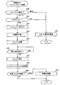
- the process of the controller 4 (engine start process) when a start request is received will be described.
- a flowchart of the processing is shown in FIG.
- the processing shown in FIG. 2 (and the processing shown in FIGS. 3 and 4) is pre-programmed in the controller 4.
- the controller 4 checks whether or not the charging plug 32 is connected to the socket 33 based on the signal CPR from the plug detection sensor 34 provided in the socket 33 (S2). If the charging plug 32 is not connected, normal engine start processing is executed (S2: NO, S3). Since normal engine start processing is also performed in a conventional hybrid vehicle, the description thereof is omitted here.
- the controller 4 checks whether charging is in progress, that is, whether power is supplied from the external power supply 31 (S4). If charging is in progress (S4: YES), the controller 4 rejects the request regardless of whether the start request is a remote start request or an in-vehicle start request, and ends the process (S7). Even when charging is not being performed (S4: NO) and the start request is an in-vehicle start request (S5: in-vehicle), the controller 4 rejects the start request (S7).
- step S6 when charging is not being performed (S4: NO) and the start request is a remote start request (S5: remote), the controller 4 checks the position of the shift lever 26 (S6). As described above, the controller 4 specifies the position of the shift lever based on the sensor data of the shift position sensor 24. If the position of the shift lever 26 is other than “parking” in the process of step S6, the controller 4 again rejects the start request (S6: NO, S12). In the figure, “P” in step S6 means “parking”. The same applies to other figures.
- the controller 4 locks the shift lever 26 and starts the engine 19 (S6: YES, S8, S9).
- “locking the shift lever 26” means that the solenoid 25 is driven so that the shift lever 26 does not move from the parking position.
- the controller 4 supplies fuel to the engine 19 while locking the axle 15 and driving the motor 12. Thus, the engine 19 is started.
- the controller 4 if the controller 4 receives a start request while the charging plug 32 is connected, the controller 4 turns off the engine 19 if charging is not performed and the shift lever 26 is in the “parking” position. Start. On the other hand, when the shift lever 26 is in a position other than “parking”, the controller 4 rejects the remote start request. When the start request is an in-vehicle start request, the controller 4 always rejects the start request if the charging plug 32 is connected.
- the hybrid vehicle 100 starts the engine 19 only in the case of a remote start request if safety is confirmed even while the charging plug 32 is connected.
- the charging plug 32 is often connected the night before and charging is set with a timer. In such a case, if charging is completed, the user can start the engine 19 using the remote switch 41 while the charging plug 32 is connected the next morning.
- the controller 4 locks the shift lever 26 after starting the engine 19 (S8). In other words, the controller 4 prohibits the shift lever 26 from moving from “parking”. This process reliably prevents the vehicle from moving while the engine 19 is running.
- FIG. 3 shows a flowchart of the process (remote start monitoring process) of the controller 4 at that time.
- step S23 is a countermeasure when the charge plug 32 is inserted again after the charge plug 32 is once pulled out.
- the controller 4 repeats the remote start monitoring process until the engine 19 stop condition is satisfied (S25: NO).
- the stop condition is typically the following condition. (1) A predetermined time has elapsed since the engine was started. (2) The driver's seat door was opened. (3) The shift lever was moved. (4) The brake pedal was depressed. (5) An engine stop request is received. (The engine stop request is sent from the remote switch 41 or another switch provided in the driver's seat.)
- the controller 4 stops the engine 19 and releases the shift lever 26 (S25: YES, S26, S27). After that, the controller 4 stops all the systems of the vehicle except for some always-operated devices (such as security devices).
- the controller 4 releases the lock of the shift lever 26 when it detects that the charging plug 32 has been pulled out. For example, when the user who has started the engine with the remote switch 41 tries to drive the car by directly pulling out the charging plug 32, the user does not need to perform an operation for unlocking and can quickly start the car. it can.
- FIG. 4 shows a flowchart of the process of the modification.
- the process of FIG. 4 is a process executed subsequent to the case where charging is being performed in step S4 of FIG. 2 (S4: YES).
- the controller 4 checks whether the start request is “remote” or “in-vehicle” (S32). When the start request is “inside the vehicle”, the controller 4 rejects the start request as in the case of FIG. 2 (S37). If the start request is “remote”, the controller 4 next checks whether or not the position of the shift lever 26 is “parking” (S33). When the position of the shift lever 26 is other than “parking”, the controller 4 again rejects the start request (S33: NO, S37).
- the controller 4 locks the shift lever 26 (S34), interrupts charging (S35), and starts the engine 19 (S36).
- the controller 4 After starting the engine 19, the controller 4 waits until the stop condition is satisfied (42: NO).
- the stop condition is as described with reference to FIG.
- the controller 4 stops the engine 19 (S43) and unlocks the shift lever 26 (S44).
- the controller 4 confirms that the charging plug 32 is connected (S45: YES), and resumes charging (S46).
- the controller 4 complete
- the user can start the engine using the remote switch 41 even when the vehicle is being charged. Also in the process of FIG. 4, the start request from the main switch 22 in the driver's seat is rejected (S32: in the vehicle, S37). The start request is also rejected when the position of the shift lever 26 is other than “parking” (S33: NO, S37). Therefore, hybrid vehicle 100 can safely start the engine in response to a remote start request from remote switch 41.
- the user can safely start the engine 19 by the remote switch 41 even when the charging plug 32 is connected.
- step S6 in FIG. 2 when the position of the shift lever is other than “parking”, the vehicle controller may move the shift lever to the “parking” position by the actuator. In that case, if the start request is remote, the engine can always be started.
- the controller 4 gives priority to charging and rejects the remote start request during quick charging or when the SOC of the main battery 5 is lower than a predetermined SOC threshold. May be programmed as follows.
- the controller 4 displays a message indicating the start request rejection on the monitor 23 (see FIG. 1) provided in the driver's seat.
- the shift lever 26 is not limited to the “gate type”.
- the technology disclosed in this specification can also be applied to a “shift-by-wire” shift mechanism and a hybrid vehicle having a joystick shift mechanism. Therefore, the mechanism for prohibiting the movement of the shift lever is not limited to the solenoid 25, and may be realized by another type of actuator.
- the configuration of the hybrid vehicle is not limited to the configuration shown in FIG.
- the technique disclosed in this specification is also preferably applied to a hybrid vehicle having an engine and a plurality of motors.
Landscapes
- Engineering & Computer Science (AREA)
- Mechanical Engineering (AREA)
- Transportation (AREA)
- Power Engineering (AREA)
- Chemical & Material Sciences (AREA)
- Combustion & Propulsion (AREA)
- Automation & Control Theory (AREA)
- General Engineering & Computer Science (AREA)
- Sustainable Energy (AREA)
- Sustainable Development (AREA)
- Life Sciences & Earth Sciences (AREA)
- Electric Propulsion And Braking For Vehicles (AREA)
- Hybrid Electric Vehicles (AREA)
- Control Of Vehicle Engines Or Engines For Specific Uses (AREA)
Abstract
Description
(1)車両外部のリモートスイッチからエンジン始動の要求を示す信号を受信した場合には、充電が行われておらず、かつ、シフトレバーのポジションが「パーキング」のポジションであればエンジンを始動し、「パーキング」以外のポジションであればリモートスタート要求を拒絶する。なお、「車両外部のリモートスイッチが送信する、エンジン始動の要求を示す信号」を以下では「リモートスタート要求」と称する。
(2)車両に備えられたスイッチからのエンジン始動の要求を示す信号は拒絶する。なお、「車両に備えられたスイッチから送られる、エンジン始動の要求を示す信号」を以下では「車内スタート要求」と称する。
(1)エンジン始動から予め定められた時間が経過した。
(2)運転席のドアが開けられた。
(3)シフトレバーが動かされた。
(4)ブレーキペダルが踏まれた。
(5)エンジン停止要求を受信した。(エンジン停止要求は、リモートスイッチ41、あるいは、運転席に備えられた他のスイッチから送られる。)
Claims (4)
- 外部の電源から充電可能なハイブリッド車であり、ハイブリッド車のコントローラが、外部の電源から電力を供給するためのプラグが車両に接続されている間に、
(1)車両外部のリモートスイッチからエンジン始動の要求(リモートスタート要求)を受信した場合、充電は行われておらず、かつ、シフトレバーのポジションがパーキングのポジションであればエンジンを始動し、パーキング以外のポジションであればリモートスタート要求を拒絶し、
(2)車両に備えられたスイッチからのエンジン始動の要求は拒絶する、
ことを特徴とするハイブリッド車。 - コントローラは、リモートスタート要求に応答してエンジンを始動する場合、パーキングポジションからのシフトレバーの移動を禁止することを特徴とする請求項1に記載のハイブリッド車。
- コントローラは、リモートスタート要求に応答してエンジンを始動したのち、前記プラグが外されたことを検知したら、シフトレバーの移動の禁止を解除することを特徴とする請求項2に記載のハイブリッド車。
- コントローラは、
外部の電源によって充電中にリモートスタート要求を受信した場合、シフトレバーのポジションがパーキングのポジションであれば充電を中止してエンジンを始動し、パーキング以外のポジションであればリモートスタート要求を拒絶し、
リモートスイッチからエンジン停止の要求を受信した場合、又は、予め定められた制限時間に達した場合、エンジンを停止するとともに充電を再開する、
ことを特徴とする請求項1から3のいずれか1項に記載のハイブリッド車。
Priority Applications (5)
| Application Number | Priority Date | Filing Date | Title |
|---|---|---|---|
| CN201180004762.3A CN103201152B (zh) | 2011-11-08 | 2011-11-08 | 混合动力车辆 |
| PCT/JP2011/075720 WO2013069094A1 (ja) | 2011-11-08 | 2011-11-08 | ハイブリッド車 |
| US13/509,115 US9051886B2 (en) | 2011-11-08 | 2011-11-08 | Hybrid vehicle |
| JP2012512143A JP5263452B1 (ja) | 2011-11-08 | 2011-11-08 | ハイブリッド車 |
| EP11838991.5A EP2778002B1 (en) | 2011-11-08 | 2011-11-08 | Hybrid vehicle |
Applications Claiming Priority (1)
| Application Number | Priority Date | Filing Date | Title |
|---|---|---|---|
| PCT/JP2011/075720 WO2013069094A1 (ja) | 2011-11-08 | 2011-11-08 | ハイブリッド車 |
Publications (1)
| Publication Number | Publication Date |
|---|---|
| WO2013069094A1 true WO2013069094A1 (ja) | 2013-05-16 |
Family
ID=48288681
Family Applications (1)
| Application Number | Title | Priority Date | Filing Date |
|---|---|---|---|
| PCT/JP2011/075720 Ceased WO2013069094A1 (ja) | 2011-11-08 | 2011-11-08 | ハイブリッド車 |
Country Status (5)
| Country | Link |
|---|---|
| US (1) | US9051886B2 (ja) |
| EP (1) | EP2778002B1 (ja) |
| JP (1) | JP5263452B1 (ja) |
| CN (1) | CN103201152B (ja) |
| WO (1) | WO2013069094A1 (ja) |
Cited By (4)
| Publication number | Priority date | Publication date | Assignee | Title |
|---|---|---|---|---|
| CN104228586A (zh) * | 2013-06-18 | 2014-12-24 | 北汽福田汽车股份有限公司 | 纯电动汽车的控制方法、系统及纯电动汽车 |
| JP2016055842A (ja) * | 2014-09-12 | 2016-04-21 | 日野自動車株式会社 | エンジンの始動装置 |
| CN112572345A (zh) * | 2020-12-04 | 2021-03-30 | 浙江吉利控股集团有限公司 | 一种混合动力汽车远程启动的方法及系统 |
| JP2023008131A (ja) * | 2021-07-05 | 2023-01-19 | トヨタ自動車株式会社 | 車両制御装置 |
Families Citing this family (12)
| Publication number | Priority date | Publication date | Assignee | Title |
|---|---|---|---|---|
| US9061598B2 (en) * | 2013-08-29 | 2015-06-23 | Ford Global Technologies, Llc | Method and system for providing charging cord reminder and fault override for plug-in electric vehicles |
| SE538693C2 (en) * | 2015-02-18 | 2016-10-18 | Scania Cv Ab | Method and control system for charging a hybrid vehicle |
| DE102015115649A1 (de) * | 2015-09-16 | 2017-03-16 | Claas Tractor Sas | Landwirtschaftliches Arbeitsfahrzeug |
| US20170241308A1 (en) * | 2016-02-24 | 2017-08-24 | Ford Global Technologies, Llc | Oil maintenance strategy for electrified vehicles |
| JP6553556B2 (ja) * | 2016-08-08 | 2019-07-31 | トヨタ自動車株式会社 | 自動車 |
| DE102017100771A1 (de) * | 2017-01-17 | 2018-07-19 | Hoppecke Advanced Battery Technology Gmbh | Batteriesystem für ein Fahrzeug |
| JP6631556B2 (ja) * | 2017-02-23 | 2020-01-15 | トヨタ自動車株式会社 | 車両及び電力伝送システム |
| CN107901757A (zh) * | 2017-11-17 | 2018-04-13 | 颐和轩智能农机(深圳)有限公司 | 履带机挂档装置及其方法 |
| US10764174B2 (en) * | 2018-01-25 | 2020-09-01 | Vmware, Inc. | Reusing domain-specific rules in a cloud-based internet of things system |
| CN110410494A (zh) * | 2019-06-05 | 2019-11-05 | 浙江鸿吉智能控制有限公司 | 一种智能集成式线控换挡系统及控制方法 |
| US11873787B2 (en) * | 2019-09-10 | 2024-01-16 | Carey Treesh | Push to start remote start system |
| CN112162546A (zh) * | 2020-06-24 | 2021-01-01 | 上汽通用五菱汽车股份有限公司 | 遥控车辆的方法、系统和存储介质 |
Citations (5)
| Publication number | Priority date | Publication date | Assignee | Title |
|---|---|---|---|---|
| JPH0986218A (ja) * | 1995-09-20 | 1997-03-31 | Tokai Rika Co Ltd | 車両機器制御装置 |
| JPH11178109A (ja) * | 1997-12-04 | 1999-07-02 | Toyota Motor Corp | ハイブリッド駆動装置 |
| JP2003042045A (ja) * | 2001-07-27 | 2003-02-13 | Matsushita Electric Ind Co Ltd | 自動車用エンジン遠隔始動装置 |
| JP2009118658A (ja) | 2007-11-07 | 2009-05-28 | Toyota Motor Corp | 電動車両 |
| JP2010119168A (ja) | 2008-11-11 | 2010-05-27 | Toyota Motor Corp | 車両およびその制御方法並びに駆動装置 |
Family Cites Families (16)
| Publication number | Priority date | Publication date | Assignee | Title |
|---|---|---|---|---|
| US6786846B2 (en) * | 2002-11-19 | 2004-09-07 | Wintecronics Co., Ltd. | Safety device for a remotely-activated power supplying system of a manual transmission vehicle |
| US7022943B1 (en) * | 2003-12-01 | 2006-04-04 | Barta Justin M | Engine block heater system and method of operation |
| JP4529738B2 (ja) | 2004-04-19 | 2010-08-25 | 株式会社デンソー | 車載機器制御装置及び車載機器制御システム |
| JP4165466B2 (ja) | 2004-07-02 | 2008-10-15 | トヨタ自動車株式会社 | 自動車およびその制御方法 |
| US7342762B2 (en) | 2005-11-10 | 2008-03-11 | Littelfuse, Inc. | Resettable circuit protection apparatus |
| EP2059899A4 (en) | 2005-12-30 | 2012-07-04 | Steven Kays | MODEL OF ADAPTATION TO ENGINEERING |
| JP4775952B2 (ja) | 2006-02-27 | 2011-09-21 | トヨタ自動車株式会社 | 建物の電力供給システム |
| JP2007245999A (ja) * | 2006-03-17 | 2007-09-27 | Toyota Motor Corp | 車両の制御装置および車両 |
| JP4279854B2 (ja) * | 2006-06-28 | 2009-06-17 | トヨタ自動車株式会社 | 車両用電源制御装置 |
| JP4483989B2 (ja) * | 2008-10-15 | 2010-06-16 | トヨタ自動車株式会社 | ハイブリッド車両 |
| JP2010104141A (ja) | 2008-10-23 | 2010-05-06 | Fujitsu Ten Ltd | 制御装置、充電制御装置、及び充電制御システム |
| JP5177060B2 (ja) | 2009-04-02 | 2013-04-03 | トヨタ自動車株式会社 | 暖機装置ならびにプラグインハイブリッド車両 |
| JP2010276003A (ja) | 2009-06-01 | 2010-12-09 | Toyota Motor Corp | 内燃機関の暖機装置 |
| US8924057B2 (en) * | 2010-03-19 | 2014-12-30 | GM Global Technology Operations LLC | Method for starting a hybrid vehicle |
| CN201816591U (zh) * | 2010-09-01 | 2011-05-04 | 浙江吉利汽车研究院有限公司 | 混合动力汽车远程遥控和安全监控系统 |
| US8527114B2 (en) * | 2011-02-25 | 2013-09-03 | Ford Global Technologies, Llc | Silent key start climate control demand |
-
2011
- 2011-11-08 CN CN201180004762.3A patent/CN103201152B/zh active Active
- 2011-11-08 JP JP2012512143A patent/JP5263452B1/ja active Active
- 2011-11-08 EP EP11838991.5A patent/EP2778002B1/en active Active
- 2011-11-08 WO PCT/JP2011/075720 patent/WO2013069094A1/ja not_active Ceased
- 2011-11-08 US US13/509,115 patent/US9051886B2/en active Active
Patent Citations (5)
| Publication number | Priority date | Publication date | Assignee | Title |
|---|---|---|---|---|
| JPH0986218A (ja) * | 1995-09-20 | 1997-03-31 | Tokai Rika Co Ltd | 車両機器制御装置 |
| JPH11178109A (ja) * | 1997-12-04 | 1999-07-02 | Toyota Motor Corp | ハイブリッド駆動装置 |
| JP2003042045A (ja) * | 2001-07-27 | 2003-02-13 | Matsushita Electric Ind Co Ltd | 自動車用エンジン遠隔始動装置 |
| JP2009118658A (ja) | 2007-11-07 | 2009-05-28 | Toyota Motor Corp | 電動車両 |
| JP2010119168A (ja) | 2008-11-11 | 2010-05-27 | Toyota Motor Corp | 車両およびその制御方法並びに駆動装置 |
Cited By (5)
| Publication number | Priority date | Publication date | Assignee | Title |
|---|---|---|---|---|
| CN104228586A (zh) * | 2013-06-18 | 2014-12-24 | 北汽福田汽车股份有限公司 | 纯电动汽车的控制方法、系统及纯电动汽车 |
| JP2016055842A (ja) * | 2014-09-12 | 2016-04-21 | 日野自動車株式会社 | エンジンの始動装置 |
| CN112572345A (zh) * | 2020-12-04 | 2021-03-30 | 浙江吉利控股集团有限公司 | 一种混合动力汽车远程启动的方法及系统 |
| JP2023008131A (ja) * | 2021-07-05 | 2023-01-19 | トヨタ自動車株式会社 | 車両制御装置 |
| JP7663037B2 (ja) | 2021-07-05 | 2025-04-16 | トヨタ自動車株式会社 | 車両制御装置 |
Also Published As
| Publication number | Publication date |
|---|---|
| JPWO2013069094A1 (ja) | 2015-04-02 |
| US20140236402A1 (en) | 2014-08-21 |
| CN103201152B (zh) | 2015-11-25 |
| JP5263452B1 (ja) | 2013-08-14 |
| EP2778002B1 (en) | 2017-12-20 |
| US9051886B2 (en) | 2015-06-09 |
| EP2778002A4 (en) | 2016-11-30 |
| EP2778002A1 (en) | 2014-09-17 |
| CN103201152A (zh) | 2013-07-10 |
Similar Documents
| Publication | Publication Date | Title |
|---|---|---|
| JP5263452B1 (ja) | ハイブリッド車 | |
| US9090177B2 (en) | Uncertified battery replacement countermeasure apparatus for electric vehicle | |
| US8538616B2 (en) | Power supply system for electrically powered vehicle, electrically powered vehicle, and method for controlling the same | |
| JP5740269B2 (ja) | 車両用制御装置 | |
| CN106004471B (zh) | 延长电动车辆中电池使用寿命的电池热调节 | |
| CN107933321B (zh) | 车辆 | |
| US11767912B2 (en) | Park lock system with added safety features | |
| US10670145B2 (en) | Electric vehicle powertrain and parking control method thereof | |
| WO2012117550A1 (ja) | 車両のシフトロック装置 | |
| CN105246751B (zh) | 插电混合动力车辆的控制装置 | |
| JP2007245999A (ja) | 車両の制御装置および車両 | |
| JP2008167618A (ja) | 車両およびその制御方法ならびに車両の制御方法をコンピュータに実行させるためのプログラムを記録したコンピュータ読取可能な記録媒体 | |
| WO2011161780A1 (ja) | 車両用制御装置および車両用制御方法 | |
| JP2014107968A (ja) | 車両の電源システム | |
| JP2009118658A (ja) | 電動車両 | |
| JP5625715B2 (ja) | 車両の制御装置および制御方法 | |
| JP2002176704A (ja) | 二電源系を有するハイブリッド自動車の駆動装置 | |
| JP2020043689A (ja) | 車両の電源システム | |
| US20150307079A1 (en) | Electrified vehicle neutral engine start | |
| JP5391805B2 (ja) | ハイブリッド自動車および異常判定方法 | |
| JP5998672B2 (ja) | 車両の充電ケーブル接続時における移動制限装置 | |
| WO2012137301A1 (ja) | 車両およびその制御方法 | |
| JP2009291016A (ja) | 車両用電源装置および車両 | |
| JP2015162968A (ja) | 車両の走行インターロックシステム | |
| US20260103166A1 (en) | Enhanced vehicle securement system |
Legal Events
| Date | Code | Title | Description |
|---|---|---|---|
| ENP | Entry into the national phase |
Ref document number: 2012512143 Country of ref document: JP Kind code of ref document: A |
|
| WWE | Wipo information: entry into national phase |
Ref document number: 13509115 Country of ref document: US |
|
| WWE | Wipo information: entry into national phase |
Ref document number: 2011838991 Country of ref document: EP |
|
| 121 | Ep: the epo has been informed by wipo that ep was designated in this application |
Ref document number: 11838991 Country of ref document: EP Kind code of ref document: A1 |
|
| NENP | Non-entry into the national phase |
Ref country code: DE |