WO2013069254A1 - 冷蔵庫 - Google Patents
冷蔵庫 Download PDFInfo
- Publication number
- WO2013069254A1 WO2013069254A1 PCT/JP2012/007092 JP2012007092W WO2013069254A1 WO 2013069254 A1 WO2013069254 A1 WO 2013069254A1 JP 2012007092 W JP2012007092 W JP 2012007092W WO 2013069254 A1 WO2013069254 A1 WO 2013069254A1
- Authority
- WO
- WIPO (PCT)
- Prior art keywords
- cooling fan
- refrigerator
- cold air
- discharge port
- chamber
- Prior art date
- Legal status (The legal status is an assumption and is not a legal conclusion. Google has not performed a legal analysis and makes no representation as to the accuracy of the status listed.)
- Ceased
Links
Images


Classifications
-
- F—MECHANICAL ENGINEERING; LIGHTING; HEATING; WEAPONS; BLASTING
- F25—REFRIGERATION OR COOLING; COMBINED HEATING AND REFRIGERATION SYSTEMS; HEAT PUMP SYSTEMS; MANUFACTURE OR STORAGE OF ICE; LIQUEFACTION SOLIDIFICATION OF GASES
- F25D—REFRIGERATORS; COLD ROOMS; ICE-BOXES; COOLING OR FREEZING APPARATUS NOT OTHERWISE PROVIDED FOR
- F25D17/00—Arrangements for circulating cooling fluids; Arrangements for circulating gas, e.g. air, within refrigerated spaces
- F25D17/04—Arrangements for circulating cooling fluids; Arrangements for circulating gas, e.g. air, within refrigerated spaces for circulating air, e.g. by convection
- F25D17/06—Arrangements for circulating cooling fluids; Arrangements for circulating gas, e.g. air, within refrigerated spaces for circulating air, e.g. by convection by forced circulation
- F25D17/062—Arrangements for circulating cooling fluids; Arrangements for circulating gas, e.g. air, within refrigerated spaces for circulating air, e.g. by convection by forced circulation in household refrigerators
- F25D17/065—Arrangements for circulating cooling fluids; Arrangements for circulating gas, e.g. air, within refrigerated spaces for circulating air, e.g. by convection by forced circulation in household refrigerators with compartments at different temperatures
-
- F—MECHANICAL ENGINEERING; LIGHTING; HEATING; WEAPONS; BLASTING
- F04—POSITIVE - DISPLACEMENT MACHINES FOR LIQUIDS; PUMPS FOR LIQUIDS OR ELASTIC FLUIDS
- F04D—NON-POSITIVE-DISPLACEMENT PUMPS
- F04D29/00—Details, component parts, or accessories
- F04D29/40—Casings; Connections of working fluid
- F04D29/52—Casings; Connections of working fluid for axial pumps
- F04D29/54—Fluid-guiding means, e.g. diffusers
- F04D29/541—Specially adapted for elastic fluid pumps
-
- F—MECHANICAL ENGINEERING; LIGHTING; HEATING; WEAPONS; BLASTING
- F25—REFRIGERATION OR COOLING; COMBINED HEATING AND REFRIGERATION SYSTEMS; HEAT PUMP SYSTEMS; MANUFACTURE OR STORAGE OF ICE; LIQUEFACTION SOLIDIFICATION OF GASES
- F25D—REFRIGERATORS; COLD ROOMS; ICE-BOXES; COOLING OR FREEZING APPARATUS NOT OTHERWISE PROVIDED FOR
- F25D2317/00—Details or arrangements for circulating cooling fluids; Details or arrangements for circulating gas, e.g. air, within refrigerated spaces, not provided for in other groups of this subclass
- F25D2317/06—Details or arrangements for circulating cooling fluids; Details or arrangements for circulating gas, e.g. air, within refrigerated spaces, not provided for in other groups of this subclass with forced air circulation
- F25D2317/063—Details or arrangements for circulating cooling fluids; Details or arrangements for circulating gas, e.g. air, within refrigerated spaces, not provided for in other groups of this subclass with forced air circulation with air guides
-
- F—MECHANICAL ENGINEERING; LIGHTING; HEATING; WEAPONS; BLASTING
- F25—REFRIGERATION OR COOLING; COMBINED HEATING AND REFRIGERATION SYSTEMS; HEAT PUMP SYSTEMS; MANUFACTURE OR STORAGE OF ICE; LIQUEFACTION SOLIDIFICATION OF GASES
- F25D—REFRIGERATORS; COLD ROOMS; ICE-BOXES; COOLING OR FREEZING APPARATUS NOT OTHERWISE PROVIDED FOR
- F25D2317/00—Details or arrangements for circulating cooling fluids; Details or arrangements for circulating gas, e.g. air, within refrigerated spaces, not provided for in other groups of this subclass
- F25D2317/06—Details or arrangements for circulating cooling fluids; Details or arrangements for circulating gas, e.g. air, within refrigerated spaces, not provided for in other groups of this subclass with forced air circulation
- F25D2317/068—Details or arrangements for circulating cooling fluids; Details or arrangements for circulating gas, e.g. air, within refrigerated spaces, not provided for in other groups of this subclass with forced air circulation characterised by the fans
- F25D2317/0681—Details thereof
-
- F—MECHANICAL ENGINEERING; LIGHTING; HEATING; WEAPONS; BLASTING
- F25—REFRIGERATION OR COOLING; COMBINED HEATING AND REFRIGERATION SYSTEMS; HEAT PUMP SYSTEMS; MANUFACTURE OR STORAGE OF ICE; LIQUEFACTION SOLIDIFICATION OF GASES
- F25D—REFRIGERATORS; COLD ROOMS; ICE-BOXES; COOLING OR FREEZING APPARATUS NOT OTHERWISE PROVIDED FOR
- F25D2500/00—Problems to be solved
- F25D2500/02—Geometry problems
Definitions
- the present invention relates to a refrigerator, and more particularly, to a structure that efficiently circulates cold air from a cooling fan into a refrigerator in a refrigerator that circulates cold air generated by a cooler into the refrigerator by an internal fan.
- the present invention relates to a refrigerator that cools a storage room by forcibly circulating cool air generated by a cooler.
- the present invention also relates to a refrigerator, and more particularly, to a structure that efficiently circulates cool air discharged from a cooling fan into a refrigerator in a refrigerator that circulates cool air generated by a cooler into the refrigerator by a cooling fan.
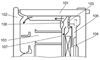
- FIG. 16 is a cross-sectional view around the cooling fan of a conventional refrigerator.
- FIG. 17 is an enlarged cross-sectional view of the vicinity of the rectifying unit of a conventional refrigerator.
- the refrigerator main body 101 is configured by a heat insulating wall, and includes at least one storage chamber 103 that opens at the front and is closed by a heat insulating door 102.
- the back of the storage chamber 103 is connected in series with a compressor (not shown), a condenser (not shown), and a decompression device (not shown), and houses a cooler 104 that constitutes a refrigerant circuit.
- an axial flow or mixed flow cooling fan 105 that circulates the cold air generated by the cooler 104 into the storage chamber 103 is provided.
- a duct 107 is provided at a position facing the cooling fan 105.
- the duct 107 is provided with a rectifying unit 106 protruding in a substantially truncated cone shape on the cooling fan 105 side.
- the duct 107 partitions the storage chamber 103 from the cooling chamber 108 having the cooler 104 and the cooling fan 105.
- a slit 109 that communicates between the storage chamber 103 and the cooling chamber 108 is provided in the flat portion of the duct 107, and the slit 109 guides the cold air discharged from the cooling fan 105 into the storage chamber 103.
- the cooling fan 105 is operated to guide the cold air generated by the cooler 104 to the storage chamber 103.
- axial flow and mixed flow fans have a flow in the direction opposite to the main flow at the central portion near the cool air discharge side of the fan due to the lower pressure inside the blades near the fan. As a result, a vortex is generated. As a result, there are problems such as increased pressure loss, increased fan noise, and reduced air volume (see, for example, Patent Document 1).
- a protruding conical rectification unit 6 is provided at a portion of the duct 107 facing the cooling fan 105.
- the rotation axis of the cooling fan 105 is inclined from the horizontal direction so that the suction direction faces the cooler side.
- the rotation axis of the cooling fan 105 is inclined from the horizontal direction so that the suction direction faces the cooler side.
- the rectifying unit 106 when the plane portion of the duct 107 is in a direction perpendicular to the rotation axis of the cooling fan 105, the space on the cold air discharge side of the cooling fan 105 is reduced, and the duct There was a risk that the pressure loss in 107 would increase, the air volume would decrease, and the noise would increase.
- the present invention provides a refrigerator with high cooling efficiency and low noise by increasing the air volume of the cooling fan by efficiently arranging the cooling fan and the rectifying unit in the cooling chamber.
- FIG. 18 is a plan sectional view of a conventional refrigerator.
- a cooling chamber 112 that generates cool air is disposed on the back surface of the storage chamber 111, and the cooling chamber 112 is separated from the other spaces by a cooling chamber cover 113.
- a cooling device 114 is disposed in the cooling chamber 112, and a cooling fan 115 is connected to the cooling fan motor 116 above the cooler 114.
- a partition plate 117 separates the air passage through which the cool air discharged from the cooling fan 115 passes and the storage chamber 111 in front of the cooling chamber cover 113.
- the partition plate 117 is integrally formed with a rectifying guide plate 118 having a conical shape at a position facing the cooling fan 115 and a discharge port 119 in a plane portion.
- the cold air flows radially along the conical surface of the rectifying guide plate 118. To do. And after diffusing radially, the cold air is sent to the storage chamber 111 through the discharge port 119.
- the rectifying guide plate 118 is integrally provided on the partition plate 117 on the front surface of the cooling fan 115, so that the discharged cold air is only in a radial flow.
- a backflow toward the center of the cooling fan 115 can be prevented, and at the same time, the rectified cool air can be sent directly from the discharge port 119 to the storage chamber 111.
- the present invention provides a refrigerator capable of efficiently cooling the storage room by delivering the cool air discharged from the cooling fan to the center of the storage room without loss.
- FIG. 19 is a cross-sectional view around the cooling fan of a conventional refrigerator.
- FIG. 20 is a front view around a cooling fan of a conventional refrigerator.
- the refrigerator 121 is formed of a heat insulating wall, and includes a freezer room 123 that opens forward and is closed by a freezer door 122 and a refrigerator room 125 that is closed by a refrigerator door 124.
- a compressor 126 (not shown), a condenser (not shown), and a decompression device (not shown) are connected in series, and a cooler 126 constituting a refrigerant circuit is accommodated.
- an axial flow type or mixed flow type cooling fan 127 that circulates the cold air generated by the cooler 126 is provided.
- a duct 129 is provided at a position facing the cooling fan 127.
- the duct 129 is formed with a rectifying portion 128 projecting substantially conically on the cooling fan 127 side.
- the duct 129 partitions the freezing chamber 123 from the cooling chamber 130 having the cooler 126 and the cooling fan 127.
- the flat portion of the duct 129 is provided with a slit 131 that allows the freezing chamber 123 and the cooling chamber 130 to communicate with each other, and cool air discharged from the cooling fan 127 is guided into the freezing chamber 123 through the slit 131.
- the heat insulation wall on the back of the freezer compartment 123 is provided with a refrigerator compartment air passage 132 so that the refrigerator compartment 123 and the refrigerator compartment 125 communicate with each other, and the cold air discharged from the cooling fan 127 is passed through the refrigerator compartment air passage 132 into the refrigerator compartment 125.
- a refrigerator compartment air passage 132 so that the refrigerator compartment 123 and the refrigerator compartment 125 communicate with each other, and the cold air discharged from the cooling fan 127 is passed through the refrigerator compartment air passage 132 into the refrigerator compartment 125.
- the cooling fan 127 is operated to guide the cold air generated by the cooler 124 to the freezer compartment 123 and the refrigerator compartment 125.
- axial flow and mixed flow fans have a flow in the direction opposite to the main flow at the central portion near the cool air discharge side of the fan due to the lower pressure inside the blades near the fan. As a result, a vortex is generated. As a result, there are problems such as increased pressure loss, increased fan noise, and reduced airflow.
- a protruding substantially conical rectifying portion 128 is provided in a portion of the duct 129 facing the cooling fan 127.
- the cold air discharged from the cooling fan 127 is blown out radially from the cooling fan 127, and the cold air passing through the slit 131 also flows radially.
- the cold air blown out from the slit 131 above the cooling fan 127 directly hits the heat insulating wall that partitions the freezer compartment 123 and the refrigerator compartment 125, and the temperature of the heat insulating wall decreases.
- the refrigerator compartment 125 is cooled by the cold air that cools the freezer compartment 123 due to heat conduction, and the freezer compartment 123 may not be efficiently cooled.
- the refrigerating room air passage 132 opens at a position opposite to the blowing direction of the cooling fan 127, and the flow direction changes by 180 degrees, so that the pressure loss of the air passage increases and flows into the refrigerating room 125. There was a risk that the air volume of the cold air would decrease.
- the cooling fan 127, the slit 131, and the refrigerator compartment air passage 132 are efficiently arranged. This increases the air volume of the cooling fan 127, reduces heat transfer from the refrigerator compartment 125 to the freezer compartment 133, and provides a refrigerator with high cooling efficiency.
- the refrigerator of the present invention includes a storage room surrounded by a heat insulating wall and having an opening on the front surface, a heat insulating door that closes the opening, and a cooler housed on the back of the storage room. Furthermore, a cooling fan that circulates the cool air generated by the cooler into the storage chamber, and a duct having a rectifying unit that protrudes toward the cooling fan at a position facing the cooling fan. And the rectification
- the refrigerator of the present invention includes a storage room, a cooler that generates cool air for cooling the storage room, a cooling fan that forcibly blows the cool air generated by the cooler to the storage room, a storage room, and a cooling fan. And a partition member positioned between the two.
- the partition member has a discharge port for sending cool air to the storage chamber, and a cool air rectifying unit that projects a portion facing the cooling fan toward the cooling fan, and at least a part of the discharge port is inside the cool air rectifying unit. Has been placed. Thereby, the cold air discharged from the cooling fan is rectified radially by the cold air rectification unit, and is discharged to the storage chamber without loss.
- the cold air discharged is discharged toward the front surface of the cooling fan.
- the cool air can be guided to the center of the storage chamber in front of the cooling fan, which conventionally could not send the cool air directly, so that the stored items can be cooled effectively.
- the refrigerator of the present invention includes a refrigerating room, a freezing room provided below the refrigerating room, a cooler provided in the freezing room, a duct partitioning the cooler and the freezing room, and cooling that circulates the cool air of the cooler.
- a fan Provides a fan.
- a rectifying unit provided at a position facing the cooling fan of the duct, a freezer compartment side discharge port for discharging cold air to the freezer compartment, and a refrigerating room side discharge port for guiding the cold air to the refrigerating chamber are provided.
- the freezer compartment discharge port is provided below the center of the cooling fan
- the refrigerator compartment discharge port is provided above the center of the cooling fan.
- cooling fan cold air from the cooling fan is blown out radially by the rectifier, and the cold air blown above the cooling fan flows to the refrigerator compartment, and the cold air blown below the cooling fan flows to the freezer compartment.
- the cool air from the cooling fan can be efficiently cooled to each chamber, so that the cooling capacity can be increased and energy saving can be achieved.
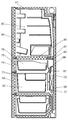
- FIG. 1 is a cross-sectional view of the refrigerator according to the first embodiment of the present invention.
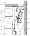
- FIG. 2 is a sectional view around the cooling fan of the refrigerator in the first embodiment of the present invention.
- FIG. 3 is an enlarged cross-sectional view of the periphery of the rectification unit of the refrigerator in the first embodiment of the present invention.
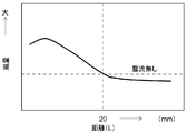
- FIG. 4 is a correlation diagram showing the relationship between the distance between the cooling fan and the rectifying unit of the refrigerator and the cooling fan air volume in the first embodiment of the present invention.
- FIG. 5 is a correlation diagram showing the relationship between the angle of the inclined portion of the rectifying unit of the refrigerator and the cooling fan air volume in the first embodiment of the present invention.
- FIG. 6 is a front view of the refrigerator in the second embodiment of the present invention.
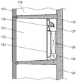
- FIG. 7 is a longitudinal sectional view of the refrigerator in the second embodiment of the present invention.
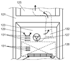
- FIG. 8 is a front view of an essential part in the second embodiment of the present invention.
- FIG. 9 is an enlarged view of a main part longitudinal section in the second embodiment of the present invention.
- FIG. 10 is a plan cross-sectional view of the main part in the second embodiment of the present invention.
- FIG. 11 is a perspective view of the storage compartment side partition member in the second embodiment of the present invention.
- FIG. 12 is a longitudinal sectional view of a refrigerator in the third embodiment of the present invention.
- FIG. 13 is sectional drawing of the refrigerator in the 4th Embodiment of this invention.
- FIG. 14 is a cross-sectional view of the vicinity of the refrigerator outlet of the refrigerator according to the fourth embodiment of the present invention.
- FIG. 15 is sectional drawing of the ice-making room side discharge port vicinity of the refrigerator in the 4th Embodiment of the same invention.
- FIG. 16 is a cross-sectional view around a cooling fan of a conventional refrigerator.
- FIG. 17 is an enlarged cross-sectional view of the vicinity of the rectifying unit of a conventional refrigerator.
- FIG. 18 is a plan sectional view of another conventional refrigerator.
- FIG. 19 is an enlarged cross-sectional view of the vicinity of a rectifying unit of still another conventional refrigerator.
- FIG. 20 is a front view of the freezer compartment of another conventional refrigerator.
- FIG. 1 is a cross-sectional view of the refrigerator in the first embodiment of the present invention.
- FIG. 2 is a cross-sectional view around the cooling fan of the same embodiment.
- FIG. 3 is an enlarged cross-sectional view of the periphery of the rectifying unit according to the embodiment.
- FIG. 4 is a correlation diagram showing the relationship between the distance between the cooling fan and the rectifying unit and the cooling fan air volume according to the embodiment.
- FIG. 5 is a correlation diagram showing the relationship between the angle of the inclined portion of the rectifying unit and the cooling fan air volume in the same embodiment.
- the duct 7 divides the cooling chamber 6 and the storage chamber 3 and has a rectifying unit 8 at a position facing the cooling fan 5.
- the cooling fan 5 is a rectangular axial fan, and includes a motor part 5a and a blade part 5b.
- the rotation axis is horizontal so that the lower end is close to the heat insulating door 2 and the upper end is far from the heat insulating door 2. Inclined with respect to the direction.
- the rectifying unit 8 has a substantially frustoconical shape having an inclined part 9 and a flat part 10, and is smoothly connected to the duct 7 by a connecting part 11.
- the rectifying unit 8 and the cooling fan 5 are installed in a positional relationship such that the distance between the plane unit 10 and the central portion on the blowing side of the cooling fan 5 is 20 mm or less, preferably about 10 mm to 15 mm.
- angle formed by the inclined portion 9 and the plane of the flat portion 10 is 20 degrees or less, preferably 10 to 15 degrees.
- the central portion of the flat surface portion 10 of the rectifying portion 8 and the rotation axis of the cooling fan 5 are arranged and configured so as to be substantially on the same line.
- the maximum dimension of the flat portion 10 of the rectifying unit 8 is equal to or smaller than the dimension of the motor unit 5a of the cooling fan 5.
- the diameter of the plane portion 10 is equal to or smaller than the diameter of the motor portion 5a of the cooling fan 5.
- the cooling fan 5 operates to guide the cold air generated by the cooler 4 to the storage chamber 3.
- the rectifying unit 8 is provided at a position facing the cooling fan 5 in order to suppress vortices generated in the vicinity of the cooling air discharge side of the cooling fan 5. Thereby, pressure loss can be reduced, the air volume of the cooling fan 5 can be increased, and noise can be reduced.
- the cooling efficiency of the cooler 4 is improved and the inside of the storage chamber 3 can be efficiently cooled.
- the rotating shaft of the cooling fan 5 is installed to be inclined with respect to the horizontal direction, so that the lower end of the cooling fan 5 is positioned forward, so that the space on the suction side of the cooling fan 5 can be increased. it can.
- a refrigerator such as a refrigerator with a short depth that does not allow a large space on the suction side of the cooling fan 5
- the pressure loss on the discharge side of the cooling fan 5 is reduced while the pressure loss on the suction side of the cooling fan 5 is reduced.
- the air volume of the cooling fan 5 can be increased.
- the rectifying unit 8 can be configured while the basic plane of the duct 7 is set to the vertical direction, the pressure loss on the discharge side of the cooling fan 5 can be reduced without increasing the pressure loss in the duct 7, and the cooling fan The air volume of 5 can be increased.
- the rectifying portion 8 of the duct 7 has a substantially truncated cone shape having the flat portion 10, the depth dimension of the duct 7 can be reduced, and the space in the storage chamber 3 can be effectively used.
- straightening part 8 shall be 20 mm or less. According to the study of the present inventor, as shown in FIG. 4, with respect to the specification of a typical cooling fan used in a refrigerator, if the distance is too large, the effect of rectification cannot be obtained, and the air volume starts from about 20 mm. The result that the effect of increase appears.
- the pressure loss can be reduced, the air volume of the cooling fan 5 can be further increased, and the noise can be reduced. . Therefore, a refrigerator with higher cooling efficiency and lower noise can be obtained.
- the angle formed by the inclined portion 9 of the rectifying portion 8 and the flat portion 10 is set to 20 degrees or less. According to the study of the present inventor, as shown in FIG. 5, for the use of a typical cooling fan used in a refrigerator, if the angle is too large, the effect of rectification cannot be obtained, and from around 20 degrees. The result that the effect of air volume increase appears.
- the pressure loss can be reduced, the air volume of the cooling fan 5 is increased, and the noise is also reduced. be able to. Therefore, a refrigerator with higher cooling efficiency and lower noise can be obtained.
- the vortex is generated on the discharge side on the blade side than the motor unit 5a, and if the diameter of the plane unit 10 is larger than that of the motor unit 5a, the pressure loss is rather. Increases, and the air volume of the cooling fan 5 is reduced.
- the diameter of the flat surface portion 10 of the rectifying portion 8 is equal to or smaller than the diameter of the motor portion 5a of the cooling fan 5, so that pressure loss can be reduced and the air volume of the cooling fan 5 can be further reduced. The noise can be reduced while increasing. Therefore, a refrigerator with higher cooling efficiency and lower noise can be obtained.
- the joint between the connecting portion 11 and the duct 7 can be smoothly connected with a curve having a radius as large as possible, thereby minimizing pressure loss due to sudden expansion and contraction.
- the effect of reducing pressure loss can be increased.
- the rectifying unit 8 and the duct 7 have been described as an integral configuration, but the same effect can be obtained by configuring the rectifying unit 8 with separate parts and retrofitting the duct 7.
- the refrigerator can be excellent in design.
- the cooling efficiency increases as the air volume of the cooling fan 5 increases.
- the rotation speed of the cooling fan 5 is reduced to ensure the same air volume by the increase in the air volume.
- the input of the cooling fan 5 can be reduced, and a refrigerator with low power consumption can be obtained.
- the diameter of the plane part 10 was demonstrated as a structure made into below the diameter of the motor part 5a of the cooling fan 5, for example, the motor part 5a of the cooling fan 5 is larger than the motor part 5a.
- the same effect can be obtained by setting the diameter of the flat portion 10 to be equal to or less than the diameter of the safety guard.
- FIG. 6 is a front view of the refrigerator according to the second embodiment of the present invention
- FIG. 7 is a sectional view taken along line 7-7 in FIG. 8 is a front view of a main part in the same embodiment
- FIG. 9 is an enlarged view of the main part in FIG.
- FIG. 10 is a plan sectional view of an essential part in the embodiment
- FIG. 11 is a perspective view of a storage chamber side partition member.
- the heat insulating box 21 that is the refrigerator main body of the refrigerator 20 includes an outer box 22 mainly using a steel plate and an inner box 23 formed of a resin such as ABS. Furthermore, the heat insulation box 21 has a foam heat insulating material such as hard foam urethane filled in the space between the outer box 22 and the inner box 23, is insulated from the surroundings, and is partitioned into a plurality of storage chambers. Yes.
- a refrigeration room 24 as a first storage room is provided at the top, and a second freezing room 25 as a fourth storage room and an ice making room 26 as a fifth storage room are provided side by side under the refrigeration room 24. ing.
- a first freezing room 27 as a second storage room is arranged below the second freezing room 25 and the ice making room 26, and a vegetable room 28 as a third storage room is arranged at the bottom.
- the refrigerating room 24 includes a refrigerating room right door 24a and a refrigerating room left door 24b, which are rotary doors, and a refrigerating room shelf 24c and a refrigerating room case 24d are appropriately disposed therein to easily organize the storage space. is doing.
- the other storage chambers have drawer doors, each of which has a second freezer compartment case 25c stored in the second freezer compartment door 25a, and an icemaker case (not shown) in the ice compartment door 26a. It is stored.
- An upper freezer compartment case 27b and a lower freezer compartment case 27c are placed on a frame (not shown) attached to the first freezer compartment door 27a.
- An upper vegetable compartment case 28b and a lower vegetable compartment case 28c are placed on a frame (not shown) attached to the vegetable compartment door 28a.
- the refrigerated room 24 is set in a refrigerated temperature zone that is a temperature that does not freeze for refrigerated storage, and is usually 1 ° C to 5 ° C.
- the vegetable room 28 has a refrigeration temperature range equivalent to the refrigeration room 24 or a vegetable temperature range of 2 ° C. to 7 ° C. that is set at a slightly higher temperature.
- the first freezer compartment 27 is set in a freezing temperature zone, and is usually set at ⁇ 22 ° C. to ⁇ 15 ° C. for frozen storage. For improving the frozen storage state, for example, ⁇ 30 ° C. It may be set at a low temperature of -25 ° C.
- the second freezer compartment 25 is a first storage compartment having a freezing temperature range equivalent to that of the first freezer compartment 27 or a slightly higher temperature setting of ⁇ 20 ° C. to ⁇ 12 ° C.
- the ice making chamber 26 makes ice with water supplied from a water storage tank (not shown) in the refrigerator compartment 24 by an automatic ice making machine (not shown) provided at the upper part of the room, and the ice is put into an ice making case 26b. Store.
- the top surface portion of the heat insulating box 21 has a stepped recess shape toward the back of the refrigerator, and a machine room 21a is formed in the stepped recess portion.
- the machine chamber 21a accommodates high-pressure components of the refrigeration cycle such as the compressor 29 and a dryer (not shown) for removing moisture. That is, the machine room 21 a in which the compressor 29 is disposed is formed by biting into the uppermost rear region in the refrigerator compartment 24.
- the compressor 29 is arranged, so that the user can use the conventional refrigerator.
- the space in the machine room at the bottom of the easy-to-use heat insulation box 21 can be effectively used as the storage room capacity, and the storage performance and usability can be greatly improved.
- the refrigeration cycle is formed of a series of refrigerant flow passages that are sequentially provided with a compressor 29, a condenser, a capillary as a decompressor, and a cooler 32, and a hydrocarbon-based refrigerant such as isobutane is enclosed as a refrigerant. Yes.
- Compressor 29 is a reciprocating compressor that compresses refrigerant by reciprocating a piston in a cylinder.
- these functional parts may be disposed in the machine room 21a.
- the decompressor constituting the refrigeration cycle is a capillary, but an electronic expansion valve that can freely control the flow rate of the refrigerant driven by the pulse motor may be used.
- the matters relating to the main part of the invention described below are the types in which the compressor 29 is disposed by providing a machine room in the rear region of the lowermost storage room of the heat insulating box 21 that has been conventionally common. It may be applied to other refrigerators.
- a cooling chamber 30 for generating cold air is provided on the back surface of the first freezing chamber 27, and the storage chamber composed of the second freezing chamber 25, the ice making chamber 26, and the first freezing chamber 27 is separated from the cooling chamber 30. Therefore, the partition member 31 is configured.
- a cooler 32 is disposed in the cooling chamber 30, and generates cold air by exchanging heat with air heated by exchanging heat with the storage chamber.
- the partition member 31 includes a storage chamber side partition member 31 a and a cooling chamber side partition member 31 b, and the cooling chamber side partition member 31 b includes a cooling fan 33.
- a space between the storage chamber side partition member 31a and the cooling chamber side partition member 31b is an air duct 31c.
- the air duct 31c guides the cold air forced out by the cooling fan 33 to the refrigerator compartment 24, the second freezer compartment 25, the ice making compartment 26, the first freezer compartment 27, and the vegetable compartment 28.
- a radiant heating means 34 made of glass tube is provided for defrosting the frost and ice adhering to the cooler 32 and its surroundings during cooling.
- a drain pan 35 for receiving defrosted water generated during defrosting is provided below the radiant heating means 34.
- a drain tube 36 penetrating from the deepest part of the drain pan 35 to the outside of the chamber is provided, and an evaporating dish 37 is provided outside the chamber on the downstream side thereof.
- the cooling fan 33 is an axial fan that rotates clockwise as viewed from the discharge surface.
- the rotation direction of the cooling fan 33 is used as a reference.
- the discharge surface of the cooling fan 33 is attached with an angle with respect to the front surface of the refrigerator 20, and the cool air is arranged to blow up obliquely upward. Further, when viewed from the front of the first freezer compartment 27, the center of the cooling fan 33 is located on the left side with respect to the central vertical line in the left-right direction of the first freezer compartment 27, and is above the upper end of the rear surface of the upper freezer compartment case 27b. Located in.
- the portion of the storage chamber side partition member 31a that faces the cooling fan 33 constitutes a cold air rectifying unit 31d that protrudes toward the cooling fan 33 side.
- the cool air rectifying unit 31 d has a substantially truncated cone shape with the rotation axis of the cooling fan 33 as the center.
- the tip of the cool air rectifying unit 31 d is configured by a plane parallel to the discharge surface of the cooling fan 33, and the diameter thereof is substantially the same as the boss diameter of the cooling fan 33.
- the part except the cold air rectification part 31d of the storage chamber side partition member 31a is configured by a substantially flat surface.
- the storage chamber side partition member 31 a is provided with a discharge port 31 e that sends cold air to the first freezer compartment 27.
- the discharge port 31e is below the center of the cool air rectifying unit 31d, above the upper end of the upper surface of the upper freezer compartment case 27b, below the lower surface of the upper freezer compartment case 27b, and behind the lower freezer compartment case 27c. Located at two locations above the top of the surface. Further, a plurality of rows of horizontally long holes are provided in one place or in a plurality of stages. Further, at least a part of the discharge port 31e is formed across the cold air rectifying unit 31d.
- the upper center hole of the discharge port 31e has a wind direction rib 39 that passes through the center of the first freezing chamber 27 and is perpendicular to the side farther from the cold air rectifying unit 31d toward the storage chamber when viewed from the front.
- the discharge port 31e by changing the position, number, and shape of the discharge port 31e, it is possible to provide an efficient air path that matches the capacity and position of the cooling fan 33, the structure of the storage room, the set temperature, and the like.
- the air direction can be controlled with higher accuracy by providing a cold air guide portion such as an air direction rib in any hole, not limited to the central hole.
- the upper discharge port 40 is provided between the partition wall 38 that partitions the refrigerator compartment 24 and the other storage chamber and the storage chamber-side partition member 31a, and cool air is sent to the second freezing chamber 25 and the ice making chamber 26.
- the partition wall 38 is provided with a damper 41, and the cold air that has passed through the damper 41 is further divided into a refrigerator compartment duct 42 and a vegetable compartment duct (not shown). 28.
- the refrigeration cycle is operated by a signal from a control device (not shown) according to the set temperature in the refrigerator, and the cooling operation is performed.
- the high-temperature and high-pressure refrigerant discharged by the operation of the compressor 29 is condensed to some extent by a condenser (not shown). Further, the refrigerant prevents condensation of the heat insulating box 21 via the side and rear surfaces of the heat insulating box 21 that is the main body of the refrigerator and a refrigerant pipe (not shown) disposed at the front opening of the heat insulating box 21. It is condensed and liquefied and reaches a capillary tube (not shown). After that, the capillary tube is depressurized while exchanging heat with a suction pipe (not shown) to the compressor 29 and becomes a low-temperature and low-pressure liquid refrigerant and reaches the cooler 32.
- the air in each storage chamber collected by the operation of the cooling fan 33 is heat-exchanged with the liquid refrigerant by the cooler 32, and the refrigerant in the cooler 32 evaporates.
- the air returned from each storage chamber becomes cool air for cooling each storage chamber again in the cooling chamber 30.
- the low-temperature cold air is diverted from the cooling fan 33 through the air duct 31c and using an air passage or a damper, and passes through the refrigerator compartment 24, the second freezer compartment 25, the ice making compartment 26, the first freezer compartment 27, and the vegetable compartment 28. Cool to each target temperature range.
- the cooling fan 33 is an axial fan that rotates clockwise, the discharged cool air flows conically so as to spread radially while turning clockwise. Therefore, by forming the cool air rectifying unit 31d according to the flow of the discharged cool air, the cool air can be smoothly sent into the air duct 31c without generating vortices. In addition, on the discharge side of the axial fan, an air flow returning toward the center is generated, but this return air flow is suppressed by making the upper surface diameter of the truncated cone of the cold air rectifying unit 31d substantially the same as the boss diameter of the fan. be able to. For this reason, the energy given to cold air from the cooling fan 33 can be utilized for ventilation without waste.
- the angle formed between the conical surface formed by the discharged cool air and the rotation axis of the cooling fan 33 differs depending on the flow rate and the number of rotations of the cooling fan 33, the angle of the conical surface of the cool air rectifying unit 31d is changed to optimize the design flow rate. Design can be done. For example, when the cooling fan 33 having a blade diameter of 90 to 110 mm is rotated around 1200 to 3000 rpm and an air volume of 0.5 to 1.0 m 3 / min is obtained, according to the experiment, the rotating shaft and the cold air rectifying unit 31d The angle formed by the conical surface is preferably 50 to 85 °.
- the kinetic energy of the discharged cold air can be efficiently recovered as pressure energy, so the discharge pressure can be increased without increasing the work of the cooling fan 33.
- a portion of the cold air that has spread along the cold air rectification unit 31d is discharged into the first freezer compartment 27 from the discharge port 31e provided in the cold air rectification unit 31d.
- a force acting along the cool air rectifying unit 31d is applied to the cool air due to the Coanda effect. Therefore, the cool air discharged from the discharge port provided in the cool air rectifying unit 31 d is smoothly discharged toward the front of the cooling fan 33. Therefore, it is possible to send the cool air to the front of the cooling fan 33, which has conventionally been difficult to send the cool air directly.
- the discharge port 31e Since the discharge port 31e has a horizontally long shape, it is strongly influenced by the cold air rectifying unit 31d, flows from the cold air toward the front of the cooling fan 33, flows through the plane portion of the storage chamber side partition member 31a, and has a high centrifugal component speed. Until continuously changing. Therefore, it is possible to obtain a wide band-shaped cold air extending from the front surface of the cooling fan 33 to the wall of the storage chamber, and to suppress temperature unevenness in the storage chamber to a minimum.
- the discharge port 31e at a position close to the side surface of the inner box 23, or just above the lower freezer compartment case 27c, the position away from the cooling fan 33, cold air can be delivered to a wider range.
- the discharge port 31e is provided below the cold air rectifying unit 31d.
- the cool air discharged from the cooling fan 33 is discharged radially along the cool air rectifying unit 31d. Therefore, cool air having a downward speed is discharged from the discharge port 31e provided below the cool air rectifying unit 31d. Since the upper hole of the discharge port 31e is disposed above the upper freezer compartment case 27b and the lower hole is disposed above the lower freezer compartment case 27c, the cold air discharged from the discharge port 31e The air is blown down inside. Therefore, since the inside of the case can be directly cooled, the stored item can be rapidly cooled.
- the upper center hole of the discharge port 31e is located at the lower right of the cooling fan 33 and is located at the center of the first freezer compartment 27. Since the cooling fan 33 is a clockwise axial fan, the cold air spreads radially while turning clockwise. At this time, since the cooling fan 33 is located on the left side with respect to the center of the first freezer compartment 27 when viewed from the front of the refrigerator 20, the center in the left-right direction of the first freezer compartment 27 corresponding to the right side of the cooling fan 33. In the vicinity, the cold air has a large downward speed.
- the cold air blown into the upper freezer compartment case 27b from the upper central hole of the discharge port 31e located at the center of the first freezer compartment 27 is discharged so as to blow down toward the center of the case, and the stored product is more effectively stored. Can be cooled.
- the hole of the upper stage center of the discharge outlet 31e is not necessarily 1st freezer compartment. It is not necessary to pass through the center of 27, and it is also possible to arrange it on the right side so that it does not completely come out of the cold air rectifying plate.
- the hole at the upper center of the discharge port 31e has the wind direction rib 39 perpendicular to the side farther from the cold air rectifying unit 31d toward the storage chamber, the component of the cold air speed spreading radially is also present in the storage chamber. Can be directed to. For this reason, it is possible to increase the amount of cold air flowing into the upper freezer compartment case 27b and cool the stored item more rapidly. Since the wind direction rib 39 can be molded integrally with the storage chamber side partition member 31a without increasing the number of parts, a structure capable of suppressing variation in the wind direction due to the solid can be made at low cost.
- wind direction rib 39 Since the wind direction rib 39 is provided only perpendicularly to the side farther from the cool air rectifying unit 31d, there is a concern that even when condensation occurs in the discharge port 31e due to a temperature difference, the condensation accumulates and grows as ice. Absent. Therefore, a quality refrigerator can be provided. If the wind direction rib 39 is configured horizontally, dew condensation does not flow down, there is a possibility that the discharge port 31e is blocked by repeating the phenomenon of being cooled by the discharged cool air and becoming ice.
- the wind direction rib 39 is provided on the storage chamber side, but may be provided on the cooling chamber side.
- the shape of the cold air guide part is not limited to the rib, and the discharge port 31e itself may protrude from the flat part of the partition member 31 toward the storage chamber, or the air path shape to the discharge port 31e may be streamlined. A similar effect can be obtained. Even at this time, it is possible to prevent the growth of ice by adopting a configuration that does not have a horizontal plane or a portion that is only partially lowered.
- At least a part of the discharge port 31e is disposed across the cold air rectifying unit 31d, so that the cold air discharged from the cooling fan 33 is radially radiated by the cold air rectifying unit 31d. It is rectified and discharged into the storage room without loss. Further, at this time, a force acts on the cool air along the cool air rectifying unit 31d due to the Coanda effect, so that the cool air when discharged is discharged toward the front of the cooling fan 33, so that conventionally, the cool air is directly sent. Since the cool air can be guided to the center of the storage chamber in front of the cooling fan 33, the stored product can be effectively cooled.
- the discharge port 31e has the cold air guide portion constituted by the wind direction rib 39, the cold air can be reliably sent to the center of the upper freezer compartment case 27b.
- the cold air guide portion can be molded integrally with the discharge port 31e, and there is no need to increase the number of parts, so that a structure that can suppress the variation in the wind direction due to the solid can be provided at low cost.
- it can be set as the structure which does not accumulate the condensation which tends to adhere to the discharge outlet 31e of the refrigerator 20, a good quality refrigerator can be provided.
- the first freezer compartment 27 is provided with an upper freezer compartment case 27b and a lower freezer compartment case 27c for storing stored items, and the cooling fan 33 is located at the upper end of the rear surface of the upper freezer compartment case 27b and the lower freezer compartment case 27c. It is arranged above. Further, since the discharge port 31e is provided below the center of the cool air rectifying unit 31d, the cool air discharged downward from the cooling fan 33 can be guided to the first freezer compartment 27. For this reason, since it becomes possible to blow cold air into the freezer compartment case from above the freezer compartment case, the stored item can be cooled more effectively.
- the discharge port 31e is disposed at a position where the center of the first freezer compartment 27 passes, and the cooling fan 33, which is a clockwise axial fan, is disposed on the left side of the center of the first freezer compartment 27.
- the cool air discharged from the cooling fan 33 spreads radially while turning clockwise. For this reason, the discharge port 31e is provided in a place where the swirl component of the speed of the cold air is downward, and the cold air can be blown downward more effectively into the upper freezer compartment case 27b.
- FIG. 12 is a longitudinal sectional view of a refrigerator according to the third embodiment of the present invention. It should be noted that the description of the parts to which the same configuration and the same technical idea as the second embodiment of the present invention can be applied is omitted, but the configuration of the second embodiment of the present invention is not limited as long as there is no problem. It is possible to apply the embodiments in combination.
- a cold room duct 51 for conveying cold air generated in the cooling room 30 to the cold room 24 is provided on the back surface of the cold room 24, and the cold room 24 is separated by the cold room partition member 52. And partitioned.
- the refrigerator compartment partition member 52 includes a front partition member 52a and a back partition member 52b, and the refrigerator compartment duct 51 is divided into a front duct 51a and a back duct 51b.
- the front partition member 52a is made of a resin molded product such as polypropylene
- the back partition member 52b is made of a foamed resin molded product having high heat insulation.
- the rear partition member 52 b is provided with a refrigerator cooling fan 53, which assists the function of the refrigerator cooling fan 33 provided in the cooling chamber 30 and circulates cold air throughout the refrigerator compartment 24.
- the refrigerator compartment cooling fan 53 is an axial fan that rotates clockwise as viewed from the discharge surface.
- the portion of the front partition member 52a that faces the refrigerating room cooling fan 53 constitutes a refrigerating room cool air rectification unit 52c that protrudes toward the refrigerating room cooling fan 53.
- the refrigerating room cool air rectification unit 52 c has a substantially truncated cone shape with the rotation axis of the refrigerating room cooling fan 53 as the center.
- the tip of the cold room refrigeration unit 52c is formed by a surface parallel to the discharge surface of the cold room cooling fan 53, and the diameter thereof is substantially the same as the boss diameter of the cold room cooling fan 53.
- the upper part of the inner box 23 constituting the refrigerator compartment 24 has a convex portion on the inner side in accordance with the shape of the machine room 21a provided on the upper part of the refrigerator 20. Therefore, the upper end of the front partition member 52 a is curved according to the shape of the inner box 23.
- the front partition member 52 a includes a refrigerating room discharge port 52 d that sends cold air to the refrigerating room 24.
- the refrigerating room discharge ports 52d are arranged in two places, upper and lower, inside the refrigerating room cold air rectification unit 52c.
- the refrigerator compartment shelf 24c is arranged at an appropriate interval so as to sandwich the two refrigerator compartment discharge ports 52d.
- the heat exchange with the cooler 32 is performed, and the generated cold air is discharged to the blower duct 31c by the cooling fan 33. A part of it is blown up, passes through the damper 41, and flows into the back duct 51b. The cold air flowing into the back duct 51b is discharged to the front duct 51a by the function of the refrigerator cooling fan 53.
- the refrigerating chamber cooling fan 53 is an axial fan that rotates clockwise, the discharged cool air flows conically so as to spread radially while turning clockwise. Therefore, the cold air can be smoothly fed into the front duct 51a without generating a vortex by making the cold room rectification unit 52c in accordance with the flow of the discharged cold air.
- the upper surface diameter of the truncated cone of the cold room rectification unit 52c is set to be substantially the same as the boss diameter of the fan. As a result, the return airflow can be suppressed, so that the energy given to the cold air from the cold room cooling fan 53 can be utilized for blowing without waste.
- a part of the cold air that spreads along the cold room cold air rectification unit 52c is discharged into the cold room 24 from the cold room discharge port 52d provided in the cold room cold air rectification unit 52c.
- a force along the refrigerating room cool air rectification unit 52c is applied to the cool air due to the Coanda effect. Therefore, the cold air discharged from the discharge port provided in the cold room refrigeration unit 52 c is smoothly discharged toward the front of the cold room cooling fan 53. Therefore, it is possible to send the cool air to the front of the refrigerating room cooling fan 53, which has conventionally been difficult to send the cool air directly.
- the refrigerator compartment shelf 24c serves as a cold air guide, and guides the cold air discharged in the vertical direction to the front. Can be cooled.
- the refrigerator compartment shelf 24c is generally configured so that the user can arbitrarily change the height, but in that case, too, the cold air will be led to the place where the stored items are placed according to the use situation. The same effect can be exhibited in any situation.
- the vertical velocity distribution of the cold air discharged from one outlet is obtained. Becomes larger. This is because the cool air discharged from the part close to the cold room rectification unit 52c goes to the front of the cold room cooling fan 53 as described above, whereas the cold air discharged from the part away from the cold room rectification unit 52c is This is because the velocity component in the radial direction, that is, the vertical velocity component increases. Therefore, by making the shape of the refrigerating chamber discharge port 52d up and down, the discharge angle of the cool air in the vertical direction can be widened, and the refrigerating chamber can be evenly cooled.
- the refrigerating room discharge port 52d is disposed inside the refrigerating room cool air rectifying unit 52c, so that the cold air discharged from the refrigerating room cooling fan 53 is refrigerated.
- the air is rectified radially by the room cold air rectification unit 52c and is discharged to the refrigerating room 24 without loss.
- the cold air discharged is discharged toward the front of the refrigerating room cooling fan 53. Accordingly, since the cool air can be guided to the center of the refrigerating chamber in front of the refrigerating chamber cooling fan 53, which has not been able to send the cool air directly in the past, the stored items can be effectively cooled.
- the refrigerator compartment shelf 24c serves as a cold air guide, and can reliably send cold air forward.
- FIG. 13 is a cross-sectional view of the refrigerator in the fourth embodiment of the present invention.
- FIG. 14 is a cross-sectional view of the vicinity of the refrigerator outlet of the refrigerator according to the embodiment.
- FIG. 15 is a cross-sectional view of the vicinity of the ice making chamber side outlet of the refrigerator in the same embodiment.
- symbol is attached
- the refrigerator 61 is closed by a drawer-type freezer compartment door 62, has a freezer case 73 inside, and has a freezer compartment 63 cooled to around minus 20 degrees.
- a refrigerating compartment 65 is closed by a rotary refrigerating compartment door 64 and cooled to about 5 degrees, and a drawer-type ice making compartment door 74 is provided between the freezing compartment 63 and the refrigerating compartment 65.
- An ice making chamber 76 that is closed and includes an ice making case 75 is provided.
- ice having a melting point of 0 degrees is stored as compared with a freezing room storing a stored product having a melting point of minus 10 degrees or less, such as ice cream. Relatively high temperature.
- the freezer compartment 63 is separated from the freezer compartment 63 by a duct 77 to form a cooling chamber 70 that houses a cooler 66 and a cooling fan 67.
- the duct 77 includes a rectifying unit 68 that protrudes in a substantially truncated cone shape at a position facing the cooling fan 67.
- the duct 77 includes a freezer compartment discharge port 78 communicating with the inside of the freezer compartment 63 and the cooling chamber 70 below the center of the cooling fan 67.
- An ice making chamber side discharge port 79 communicating with the inside of the ice making chamber 76 is provided.
- a partition wall 80 is provided between the ice making chamber 76 and the refrigerating chamber 65, and a partition wall 80 is provided between the ice making chamber 76 and the refrigerating chamber 65.
- a cooling chamber side discharge port 81 communicating the cooling chamber 70 and the refrigerating chamber 65 is provided in the cooling chamber 70 of the partition wall 80. It has.
- a damper 82 for selectively closing and opening the refrigerator compartment side discharge port 81 is provided in the refrigerator compartment side discharge port 81.
- the ice making chamber side discharge port 79 and the refrigerator compartment side discharge port 81 are opened at positions shifted left and right as viewed from the front of the refrigerator.
- the ice making chamber side discharge port 79 is provided on the front side of the refrigerator 61 with respect to the basic plane of the duct 77, and the refrigerator side discharge port 81 is provided on the back side.
- a wind direction adjusting rib 83 is provided on the upper side of the opening at an angle such that the cold air flows horizontally or downward.
- the cooling fan 67 operates to guide the cold air generated by the cooler 66 to each room.
- the rectifying unit 68 is provided at a position facing the cooling fan 67.
- the cold air blown into the freezing chamber 63 flows downward, and flows into the freezing case 73, thereby cooling the stored items in the freezing case 73 and not cooling the partition wall 80 directly.
- the partition wall 80 may be cooled and heat loss may occur.
- the ice making chamber 76 only needs to be cooled to a temperature higher than that of the freezer compartment 63, and the air volume of the cold air is reduced by making the area of the ice making chamber side discharge port 79 smaller than the area of the freezing chamber side discharge port 78. is doing. Therefore, even if the internal temperature is high and cold air directly hits the partition wall 80, heat loss can be reduced as compared with the case where the cold air hits the freezer compartment 3.
- the wind direction adjusting rib 83 directs the flow of cool air downward from the horizontal to guide the cool air into the ice making case 75, and the partition wall 80 is not directly cooled by the cool air.
- a damper 82 closes and opens the refrigerating chamber side discharge port 81 in the refrigerating chamber side discharge port 81 in order to selectively flow cold air to the refrigerating chamber 65. It has.
- the ice making chamber side outlet 79 and the refrigeration chamber side outlet 81 are shifted from side to side when viewed from the front of the refrigerator 61 and are shifted back and forth when viewed from the side. . Further, the duct 77 is inclined to each of the ice making chamber side outlet 79 and the refrigerator compartment side outlet 81 to smoothly connect them.
- the ice making chamber 76 is described as being between the freezing chamber 63 and the refrigerating chamber 65.
- a chiller chamber having a high temperature of around 0 degrees a greater effect can be obtained. It is done.
- the ice making chamber 76 is provided between the freezing chamber 63 and the refrigerating chamber 65.
- the ice making chamber 76 and the chiller chamber are provided side by side, and the refrigerating chamber side discharge port 81 is provided. By providing outlets for cooling each room on the left and right sides, it is possible to support a multi-door refrigerator.
- the damper 82 is described as being provided only in the refrigerator-side discharge port 81, but more accurate temperature control can be performed by providing the ice-making chamber-side discharge port 79 with a damper. it can. Furthermore, by controlling the cooling fan 67 and the number of rotations of the compressor according to the opening / closing of the damper, useless cooling can be eliminated and a more efficient refrigerator can be obtained.
- the present invention includes a storage chamber surrounded by a heat insulating wall and having an opening on the front surface, a heat insulating door that closes the opening, a cooler housed on the back of the storage chamber, and cool air generated by the cooler into the storage chamber.
- a cooling fan to circulate is provided.
- straightening part protruded to the cooling fan side in the position facing a cooling fan is provided,
- straightening part is made into the substantially truncated cone shape provided with the inclination part and the plane part.
- the basic plane of the duct is substantially vertical, the cooling fan is inclined with respect to the vertical direction, and the rectifying unit is inclined so that the rectifying unit faces the cooling fan.
- the present invention can reduce the pressure loss on the blow-out side without increasing the pressure loss on the suction side of the cooling fan while suppressing the depth dimension of the cooling chamber, and further increases the storage efficiency and the cooling efficiency. Can provide a refrigerator with low noise.
- the present invention is configured such that the substantially central portion of the flat portion of the rectifying portion and the rotation axis of the cooling fan are substantially on the same line. With this configuration, the present invention can enhance the rectification effect of the rectification unit while effectively utilizing the space of the cooling chamber.
- the distance between the flat portion and the cooling fan front end surface is 20 mm or less.
- the angle between the inclined portion of the rectifying portion and the plane perpendicular to the rotation axis of the cooling fan is set to 20 degrees or less.
- the maximum dimension of the flat part of the rectifying part is equal to or less than the dimension of the motor part of the cooling fan.
- the refrigerator of the present invention includes a storage room, a cooler that generates cool air for cooling the storage room, a cooling fan that forcibly blows the cool air generated by the cooler to the storage room, a storage room, and a cooling fan. And a partition member positioned between the two. And the partition member has a discharge port for sending cool air to the storage chamber, and a cool air rectification unit that projects a portion facing the cooling fan to the cooling fan side, and at least a part of the discharge port is in the cold air rectification unit Has been placed. Thereby, the cold air discharged from the cooling fan is rectified radially by the cold air rectification unit, and is discharged to the storage chamber without loss.
- the cold air discharged is discharged toward the front surface of the cooling fan.
- the cool air can be guided to the center of the storage chamber in front of the cooling fan, which conventionally could not send the cool air directly, so that the stored items can be cooled effectively.
- the discharge port is provided with a cold air guide part.
- the present invention can arbitrarily control the direction of the cool air discharged from the discharge port.
- the cold air guide portion is constituted by a rib provided on the partition member.
- the present invention can form the cold air guide part integrally with the discharge port, and it is not necessary to increase the number of parts. Can do.
- it can be set as the structure which does not accumulate the condensation which tends to adhere to the discharge outlet of a refrigerator, a quality refrigerator can be provided.
- the storage chamber includes one or a plurality of storage cases for storing stored items, and the cooling fan is disposed above the upper end of at least one back surface of the storage case. Furthermore, the discharge port arrange
- straightening part is provided below the center of a cold air rectification
- the present invention can guide the cold air discharged downward from the cooling fan to the storage chamber, so that it becomes possible to blow cold air into the storage case from above the storage case. The storage can be effectively cooled.
- the cooling fan is arranged on the opposite side to the rotation direction with respect to the central vertical line in the horizontal direction of the storage room when viewed from the front of the refrigerator main body.
- the refrigerator of the present invention includes a refrigerator compartment, a freezer compartment provided below the refrigerator compartment, a cooler provided in the refrigerator compartment, a duct separating the cooler and the freezer compartment, and cooling for circulating the cooler air. Equipped with a fan. And the rectification
- an ice making chamber is provided between the refrigerator compartment and the freezer compartment, and an ice making chamber discharge port for discharging cold air to the ice making chamber is provided.
- the ice making chamber side discharge port is provided on the front side
- the refrigerator compartment side discharge port is provided on the back side
- the duct is provided near the refrigerator compartment side discharge port on the back side, while the ice making chamber side discharge port
- the neighborhood is inclined to the front side.
- a wind direction adjusting unit is provided at the upper part of the ice making chamber side outlet so that the discharged cool air flows horizontally or downward.
- the present invention does not apply cold air from the cooling fan to the heat insulating wall between the refrigerator compartment and the ice making room, so that cold air can be efficiently blown out to each room, and a refrigerator with higher cooling efficiency is provided. Can do.
- the present invention is useful as refrigerators of various types and sizes for home use and business use. Further, the present invention can be applied to any cooling device provided with a cooling fan.
Landscapes
- Engineering & Computer Science (AREA)
- Mechanical Engineering (AREA)
- General Engineering & Computer Science (AREA)
- Chemical & Material Sciences (AREA)
- Combustion & Propulsion (AREA)
- Physics & Mathematics (AREA)
- Thermal Sciences (AREA)
- Cold Air Circulating Systems And Constructional Details In Refrigerators (AREA)
Abstract
本発明は、貯蔵室背面に収納された冷却器と、冷却器で生成した冷気を貯蔵室内へ循環させる冷却ファン(5)を備える。また、冷却ファン(5)と対向する位置に冷却ファン(5)側へ突出した整流部(8)を有したダクト(7)とを備える。さらに、整流部(8)は傾斜部(9)と平面部(10)とを備えた略円錐台状とする。このことにより、ダクト(7)の奥行き寸法を抑えながら、冷却ファン(5)の吸い込み側の圧力損失を増加させずに、吹き出し側の圧力損失を低減することができる。さらに、収納効率および冷却効率が高く、騒音の低い冷蔵庫を提供することができる。
Description
本発明は、冷蔵庫に関し、特に、冷却器で生成した冷気を庫内ファンによって庫内に循環させる冷蔵庫において、冷却ファンの冷気を庫内へ効率よく循環させる構造に関する。
また、本発明は、冷却器で生成した冷気を強制循環させて貯蔵室を冷却する冷蔵庫に関するものである。
また、本発明は、冷蔵庫に関し、特に、冷却器で生成した冷気を冷却ファンによって庫内に循環させる冷蔵庫において、冷却ファンから吐出する冷気を庫内へ効率よく循環させる構造に関する。
図16は、従来の冷蔵庫の冷却ファン周囲の断面図である。図17は従来の冷蔵庫の整流部周辺を拡大した断面図である。図16、図17において、冷蔵庫本体101は断熱壁により構成され、前部に開口し、断熱扉102により閉塞された貯蔵室103を少なくとも一つ備える。貯蔵室103の背面には圧縮機(図示せず)、凝縮器(図示せず)、減圧装置(図示せず)と直列に接続され、冷媒回路を構成する冷却器104を収納する。冷却器104の上部には、冷却器104により生成された冷気を貯蔵室103内へと循環させる、軸流式または斜流式の冷却ファン105を備えている。冷却器104の断熱扉102側には、冷却ファン105と対向する位置に、冷却ファン105側に略円錐台状に突出した整流部106を設けたダクト107を備えている。このダクト107は貯蔵室103を冷却器104及び冷却ファン105のある冷却室108と仕切っている。
また、ダクト107の平面部分には、貯蔵室103と冷却室108を連通するスリット109を設け、このスリット109が冷却ファン105から吐出した冷気を貯蔵室103内へと導いている。
冷蔵庫運転中、冷却器104で生成された冷気を貯蔵室103へと導くべく冷却ファン105が運転する。一般的に、軸流式、斜流式ファンは、ファン近傍の羽根部よりも内側の圧力が低くなることにより、ファンの冷気吐出側近傍の中心部で、主流とは逆方向の流れが生じることにより、渦が発生する。これにより、圧力損失が大きくなり、ファンの騒音が高くなったり、風量が減少したりするなどの課題があった(例えば、特許文献1参照)。
従来の冷蔵庫では、この課題を解決するために、ダクト107の冷却ファン105と対向する部分に、突出した円錐状の整流部6を設けている。
しかしながら、例えば奥行きの短い冷蔵庫においては冷却ファン105の吸い込み側の空間を大きく取るために、冷却ファン105の回転軸を、吸い込み方向が冷却器側を向くように、水平方向から傾けて配置する場合がある。この場合、上記従来の構成では、ダクト107の平面部分を鉛直方向としたとき、冷却ファン105の下部が上部に比べてダクト107の平面部分に近づくことになる。このため、整流部106と冷却ファン105の下の隙間が小さく、上の隙間が大きくなる。その結果、整流部106による圧力損失低減効果が小さくなり、風量が低下したり、騒音が大きくなったりする恐れがあった。
また、整流部106による圧力低減効果を大きくするために、ダクト107の平面部分を冷却ファン105の回転軸と垂直方向とした場合には、冷却ファン105の冷気吐出側の空間が小さくなり、ダクト107内での圧力損失が増加し、風量が低下したり、騒音が大きくなったりする恐れがあった。
本発明は、冷却室内で冷却ファンと整流部を効率良く配置することにより、冷却ファンの風量を増加させ、冷却効率が高く、騒音の低い冷蔵庫を提供する。
また、省エネルギに対する要求が厳しくなる中、冷却器で生成した冷気を強制循環させて貯蔵室を冷却する冷蔵庫においては、その冷却器の冷凍効率だけでなく、冷却ファン冷却ファンの送風効率も重視されている。そのため、冷却ファン冷却ファンから吐出された冷気を効率よく運搬する送風技術が重要となる。従来は冷却ファン冷却ファンの吐出側に整流部を設ける構成が用いられている(例えば、特許文献1参照)。
以下、図面を参照しながら従来の冷蔵庫を説明する。
図18は従来の冷蔵庫の平面断面図である。図において、貯蔵室111の背面には、冷気を生成する冷却室112が配設され、冷却室カバー113により、冷却室112とその他の空間を隔てている。冷却室112には、冷却器114が配設され、その上方において、冷却ファン115が、冷却ファンモータ116に接続されている。さらに、冷却室カバー113の前面には、仕切板117が、冷却ファン115より吐出された冷気の通る風路と貯蔵室111を隔てている。仕切板117には、冷却ファン115に対向する位置に円錐形状を有する整流案内板118と、平面部分に吐出口119とを一体で形成する。
以上のように構成された冷蔵庫について、以下その動作を説明する。
冷却室112内の空気が冷却器114により冷却され、冷気となって冷却ファン115によって整流案内板118に向けて吐出されると、その冷気は整流案内板118の円錐面に沿って放射状に流出する。そして放射状に拡散し後、冷気は吐出口119を通って貯蔵室111に送られる。
以上のように、従来の冷蔵庫では、冷却ファン115の前面の仕切板117に整流案内板118を一体に設けることで、吐出冷気を放射状の流れのみとする。そのことで、冷却ファン115の中心に向かう逆流する流れを防止すると同時に、整流された冷気を直接吐出口119より貯蔵室111に送ることができる。更に、それと同時に冷気の損失を最小限に押さえ、効率よく貯蔵室を冷却できる冷蔵庫を提供することができる。
しかしながら、従来の冷蔵庫の構成では、冷気は、仕切板117の平面部分に設けられた吐出口119より吐出される際、放射状に整流されていることから、外向きに広がろうとする力が大きい。このために、貯蔵物が多い貯蔵室111の中央である冷却ファン115の正面を冷やしにくいという問題があった。
さらに、外向きに吐出された冷気は貯蔵室111の内壁に沿って流れるため、冷蔵庫本体の壁を通した外気との熱交換が促進され、消費電力を増大させる可能性があった。
本発明は、冷却ファンより吐出された冷気をロスなく貯蔵室中央に届け、効率よく貯蔵室を冷却することができる冷蔵庫を提供する。
また、図19は、従来の冷蔵庫の冷却ファン周囲の断面図である。図20は従来の冷蔵庫の冷却ファン周囲の正面図である。
図19、図20において、冷蔵庫121は断熱壁により構成され、前方を開口し冷凍室扉122により閉塞された冷凍室123と冷蔵室扉124により閉塞された冷蔵室125を備える。冷凍室123の背面には、圧縮機(図示せず)、凝縮器(図示せず)、減圧装置(図示せず)と直列に接続され、冷媒回路を構成する冷却器126を収納する。冷却器126の上部には、冷却器126により生成された冷気を循環させる、軸流式または斜流式の冷却ファン127を備えている。冷却器126の冷凍室扉122側には、冷却ファン127と対向する位置に、冷却ファン127側に略円錐状に突出した整流部128を形成したダクト129を備える。そして、ダクト129は、冷凍室123を冷却器126及び冷却ファン127のある冷却室130と仕切っている。
ダクト129の平面部分には、冷凍室123と冷却室130を連通するスリット131を設け、冷却ファン127から吐出した冷気を、スリット131を通して冷凍室123内へと導いている。
また、冷凍室123背面の断熱壁には冷凍室123と冷蔵室125が連通するように冷蔵室風路132を設け、冷却ファン127から吐出した冷気を、冷蔵室風路132を通して冷蔵室125内へと導いている。
冷蔵庫運転中、冷却器124で生成された冷気を冷凍室123及び冷蔵室125へと導くべく冷却ファン127を運転する。一般的に、軸流式、斜流式ファンは、ファン近傍の羽根部よりも内側の圧力が低くなることにより、ファンの冷気吐出側近傍の中心部で、主流とは逆方向の流れが生じることにより、渦が発生する。これにより、圧力損失が大きくなり、ファンの騒音が高くなったり、風量が減少したりするなどの課題があった。
従来の冷蔵庫では、この課題を解決するために、ダクト129の冷却ファン127と対向する部分に、突出した略円錐状の整流部128を設けている。
しかしながら、上記従来の構成では、冷却ファン127から吐出する冷気は、冷却ファン127から放射状に吹き出され、スリット131を通過した冷気も放射状に流れる。この時、冷却ファン127よりも上にあるスリット131から吹き出された冷気は、冷凍室123と冷蔵室125を仕切る断熱壁に直接当たり、断熱壁の温度が低下する。これにより、熱伝導により、冷凍室123を冷却する冷気により冷蔵室125が冷却されることになり、冷凍室123を効率よく冷却できなくなる恐れがあった。
また、冷蔵室風路132は、冷却ファン127の吹き出し方向と逆向きの位置に開口しており、流れ方向が180度変化することにより、風路の圧力損失が大きくなり、冷蔵室125へ流れる冷気の風量が低下する恐れがあった。
本発明は、冷却ファン127とスリット131、冷蔵室風路132を効率良く配置する。このことにより、冷却ファン127の風量を増加させるとともに、冷蔵室125から冷凍室133への熱移動を小さくし、冷却効率が高い冷蔵庫を提供する。
本発明の冷蔵庫は、断熱壁で囲われ前面に開口部を有した貯蔵室と、開口部を閉塞する断熱扉と、貯蔵室背面に収納された冷却器を有する。更に冷却器で生成した冷気を貯蔵室内へ循環させる冷却ファンと、冷却ファンと対向する位置に冷却ファン側へ突出した整流部を有したダクトとを備える。そして、整流部は傾斜部と平面部とを備えた略円錐台状とした。
これにより、ダクトの奥行き寸法を抑えながら、冷却ファンの吸い込み側の圧力損失を増加させずに、吹き出し側の圧力損失を低減することができ、収納効率および冷却効率が高く、騒音の低い冷蔵庫を提供することができる。
また、本発明の冷蔵庫は、貯蔵室と、貯蔵室を冷却する冷気を生成する冷却器と、冷却器で生成された冷気を強制的に貯蔵室に送風する冷却ファンと、貯蔵室と冷却ファンとの間に位置する仕切部材とを備える。仕切部材は、冷気を貯蔵室へ送る吐出口と、冷却ファンに対向する部分を冷却ファン側に突出させた冷気整流部とを有し、吐出口の少なくとも一部が、冷気整流部の内部に配置されている。これにより、冷却ファンより吐出された冷気は冷気整流部によって放射状に整流され、そのままロスすることなく貯蔵室へ吐出される。またこのとき、冷気にはコアンダ効果により冷気整流部に沿うように力が働くため、吐出される際の冷気は冷却ファン正面に向けて吐出される。これにより従来では直接冷気を送ることができなかった冷却ファン正面の貯蔵室中央へ冷気を導くことができるため、効果的に貯蔵物を冷却することができる。
また、本発明の冷蔵庫は、冷蔵室と、冷蔵室より下部に備えた冷凍室と、冷凍室内に備えた冷却器と、冷却器と冷凍室を仕切るダクトと、冷却器の冷気を循環させる冷却ファンを設ける。さらに、ダクトの冷却ファンと対向する位置に備えた整流部と、冷気を冷凍室へ吐出する冷凍室側吐出口と、冷気を冷蔵室へと導く冷蔵室側吐出口とを設ける。それに加えて、冷凍室側吐出口を冷却ファンの中心よりも下に設け、冷蔵室側吐出口を冷却ファンの中心よりも上に設ける。
これにより、冷却ファンによる冷気を整流部により放射状に吹き出し、冷却ファンより上へ吹き出した冷気は冷蔵室へ、冷却ファンより下へ吹き出した冷気は冷凍室へと流れる。このことにより、冷却ファンからの冷気を各室へ効率よく冷却することができるので、冷却能力を高めることができるとともに、省エネを図ることができる。
以下、本発明の第1の実施の形態における冷蔵庫について、図面を参照しながら説明する。なお、この実施の形態によってこの発明が限定されるものではない。
(第1の実施の形態1)
図1は本発明の第1の実施の形態における冷蔵庫の断面図である。図2は同実施の形態の冷却ファン周囲の断面図である。図3は同実施の形態の整流部周囲を拡大した断面図である。図4は同実施の形態の冷却ファンと整流部の距離と冷却ファン風量の関係を示した相関図である。図5は同実施の形態の整流部の傾斜部の角度と冷却ファン風量の関係を示した相関図である。
図1は本発明の第1の実施の形態における冷蔵庫の断面図である。図2は同実施の形態の冷却ファン周囲の断面図である。図3は同実施の形態の整流部周囲を拡大した断面図である。図4は同実施の形態の冷却ファンと整流部の距離と冷却ファン風量の関係を示した相関図である。図5は同実施の形態の整流部の傾斜部の角度と冷却ファン風量の関係を示した相関図である。
図1から図3に示すように、ダクト7は、冷却室6と貯蔵室3を仕切るとともに、冷却ファン5と対向する位置に整流部8を有する。
冷却ファン5は、矩形状の軸流ファンで、モーター部5aと羽根部5bから構成されており、下端が断熱扉2側に近く、上端が断熱扉2から遠くなるように、回転軸が水平方向に対して傾いて配設されている。
整流部8は、傾斜部9と平面部10を有した略円錐台状の形状をしており、連結部11によってダクト7と滑らかに繋がっている。
次に整流部8の詳細な構成について説明する。整流部8と冷却ファン5は、平面部10と冷却ファン5の吹き出し側中心部との距離が20mm以下、好ましくは10mmから15mm程度となるような位置関係で設置されている。
また、傾斜部9と平面部10の面とがなす角度は20度以下、好ましくは10度から15度程度の角度となるような構成としている。
また、整流部8の平面部10の略中心部と冷却ファン5の回転軸とが略同一線上となるように配置構成している。
また、整流部8の平面部10の最大寸法を、冷却ファン5のモーター部5aの寸法と同等以下としている。具体的には、平面部10の直径は、冷却ファン5のモーター部5aの直径の同等以下としている。
以上のように構成された冷蔵庫について、以下その動作を説明する。
冷蔵庫運転中、冷却器4で生成された冷気を貯蔵室3へと導くべく冷却ファン5が運転する。この時、冷却ファン5の冷気の吐出側近傍に発生する渦を抑制すべく、冷却ファン5と対向する位置に整流部8を設けている。これにより、圧力損失を低くすることができ、冷却ファン5の風量を増加させることができるとともに、騒音を低減することができる。
冷却ファン5の風量が増加すると、冷却器4の冷却効率が向上し、貯蔵室3内を効率よく冷却することができる。
ここで、冷却ファン5の回転軸は、水平方向に対して傾いて設置されていることにより、冷却ファン5の下端が前方に位置するため、冷却ファン5の吸い込み側の空間を大きくとることができる。これにより、奥行きが短い冷蔵庫など、冷却ファン5の吸い込み側の空間を大きく取れない冷蔵庫において、冷却ファン5の吸い込み側の圧力損失を低減しつつ、冷却ファン5の吐出側の圧力損失を低減することができ、冷却ファン5の風量を増加させることができる。一方、ダクト7の基本平面を鉛直方向としつつ整流部8を構成できるため、ダクト7内での圧力損失を増加させることなく冷却ファン5の吐出側の圧力損失を低減することができ、冷却ファン5の風量を増加させることができる。
従って、冷却室6、ダクト7全体としての圧力損失を低減することができ、冷却効率が高く、騒音の低い冷蔵庫とすることができる。
また、ダクト7の整流部8は平面部10を有した略円錐台状の形状をしているので、ダクト7の奥行寸法を小さくでき、貯蔵室3内のスペースの有効活用が可能となる。
また、本実施の形態においては、整流部8の平面部10との距離は、20mm以下としている。本発明者の検討によれば、図4に示すように、冷蔵庫に使用される代表的な冷却ファンの仕様に対しては、距離が大きすぎると整流の効果は得られず、20mm前後から風量増加の効果が現れてくるとの結果を得ている。
よって、整流部8の平面部10と冷却ファン5の距離を20mm以下としたことにより、圧力損失を低減することができ、より冷却ファン5の風量を増加させるとともに、騒音も低くすることができる。従って、より冷却効率が高く騒音の低い冷蔵庫とすることができる。
また、本実施の形態においては、整流部8の傾斜部9と平面部10がなす角度は20度以下としている。本発明者の検討によれば、図5に示すように、冷蔵庫に使用される代表的な冷却ファンの使用に対しては、角度が大きすぎると整流の効果は得られず、20度前後から風量増加の効果が現れてくるとの結果を得ている。
よって、整流部8の、傾斜部9と平面部10のなす角度を20度以下としたことにより、圧力損失を低減することができ、より冷却ファン5の風量を増加させるとともに、騒音も低くすることができる。従って、より冷却効率が高く騒音の低い冷蔵庫とすることができる。
また、軸流式ファンや斜流式ファンにおいて、吐出側で渦が発生するのは、モーター部5aよりも羽根側であり、モーター部5aよりも平面部10の直径が大きいと、かえって圧力損失が大きくなり、冷却ファン5の風量を低下させることになる。本実施の形態においては、整流部8の平面部10の直径を、冷却ファン5のモーター部5aの直径と同等以下としているため、圧力損失を低減することができ、より冷却ファン5の風量を増加させるとともに、騒音も低くすることができる。従って、より冷却効率が高く騒音の低い冷蔵庫とすることができる。
尚、本実施の形態では、連結部11とダクト7との繋ぎ目を、できるだけ大きな半径の曲線で滑らかに繋ぐことにより、急拡大、急縮小による圧力損失を最小限にすることができる、より圧力損失低減効果を高くすることができる。
また、本実施の形態では、整流部8とダクト7は一体の構成として説明したが、別部品で整流部8を構成し、ダクト7に後付けする構成としても、同様の効果が得られる。
また、ダクト7の整流部8による凹みを化粧版などで隠すことにより、貯蔵室3内奥面の凹凸が無くなり、デザイン性に優れた冷蔵庫とすることができる。
また、本実施の形態では、冷却ファン5の風量が増加することにより、冷却効率が高くなるとして説明したが、風量増加した分、冷却ファン5の回転数を低くして同等風量を確保することにより、冷却ファン5の入力を低くでき、消費電力量の低い冷蔵庫とすることもできる。
また、本実施の形態においては、平面部10の直径を、冷却ファン5のモーター部5aの直径以下とする構成として説明したが、例えば冷却ファン5のモーター部5aに、モーター部5aよりも大きな直径の安全ガードのような部品が取り付けられている場合には、平面部10の直径は安全ガードの直径以下とすることで同様の効果が得られる。
次に本発明の第2および第3の実施の形態について、図面を参照しながら説明する。なお、この実施の形態によってこの発明が限定されるものではない。
(第2の実施の形態)
図6は本発明の第2の実施の形態1における冷蔵庫の正面図、図7は図6における7-7断面図である。また、図8は同実施の形態における要部正面図、図9は図7における要部拡大図である。また、図10は同実施の形態における要部平面断面図、図11は貯蔵室側仕切部材の斜視図である。
図6は本発明の第2の実施の形態1における冷蔵庫の正面図、図7は図6における7-7断面図である。また、図8は同実施の形態における要部正面図、図9は図7における要部拡大図である。また、図10は同実施の形態における要部平面断面図、図11は貯蔵室側仕切部材の斜視図である。
図6から図11に示すように、冷蔵庫20の冷蔵庫本体である断熱箱体21は、主に鋼板を用いた外箱22と、ABSなどの樹脂で成型された内箱23を有する。さらに、断熱箱体21は、外箱22と内箱23との間の空間に発泡充填される硬質発泡ウレタンなどの発泡断熱材を有し、周囲と断熱され、複数の貯蔵室に区画されている。
最上部に第一の貯蔵室としての冷蔵室24、その冷蔵室24の下部に第四の貯蔵室としての第二の冷凍室25と第五の貯蔵室としての製氷室26が横並びに設けられている。その第二の冷凍室25と製氷室26の下部には第二の貯蔵室としての第一の冷凍室27、そして最下部に第三の貯蔵室としての野菜室28が配置されている。
冷蔵室24は、回転扉である冷蔵室右扉24aと冷蔵室左扉24bを備え、内部には、冷蔵室棚24cや冷蔵室ケース24dが適切に配設され、貯蔵空間を整理し易く構成している。一方、その他の貯蔵室は引き出し式扉を有し、それぞれ第二の冷凍室扉25aには第二の冷凍室ケース25cが収納され、製氷室扉26aには製氷室ケース(図示せず)が収納されている。第一の冷凍室扉27aに取り付けられたフレーム(図示せず)には上段冷凍室ケース27bおよび下段冷凍室ケース27cが載置せれている。また、野菜室扉28aに取り付けられたフレーム(図示せず)には上段野菜室ケース28bおよび下段野菜室ケース28cが、載置されている。
冷蔵室24は冷蔵保存のために凍らない温度である冷蔵温度帯に設定されており、通常1℃から5℃となっている。野菜室28は冷蔵室24と同等の冷蔵温度帯もしくは若干高い温度設定の野菜温度帯2℃から7℃としている。第一の冷凍室27は冷凍温度帯に設定されており、冷凍保存のために通常-22℃から-15℃で設定されているが、冷凍保存状態の向上のために、例えば-30℃や-25℃の低温で設定されることもある。
第二の冷凍室25は、第一の冷凍室27と同等の冷凍温度帯または若干高い温度設定-20℃から-12℃の第一の収納区画である。製氷室26は、冷蔵室24内の貯水タンク(図示せず)から送られた水で室内上部に設けられた自動製氷機(図示せず)で氷を作り、その氷を製氷室ケース26bに貯蔵する。
断熱箱体21の天面部は冷蔵庫の背面方向に向かって階段状に凹みを設けた形状であり、この階段状の凹部に機械室21aを形成している。機械室21aには、圧縮機29、水分除去を行うドライヤ(図示せず)等の冷凍サイクルの高圧側構成部品が収容されている。すなわち、圧縮機29を配設する機械室21aは、冷蔵室24内の最上部の後方領域に食い込んで形成されている。
このように、手が届きにくくデッドスペースとなっていた断熱箱体21の最上部の貯蔵室後方領域に機械室21aを設けて圧縮機29を配置することにより、従来の冷蔵庫で、使用者が使いやすい断熱箱体21の最下部にあった機械室のスペースを貯蔵室容量として有効に利用することができ、収納性や使い勝手を大きく改善することができる。
冷凍サイクルは、圧縮機29と凝縮器と減圧器であるキャピラリーと冷却器32とを順に備えた一連の冷媒流路から形成されており、冷媒として炭化水素系冷媒である例えばイソブタンが封入されている。
圧縮機29はピストンがシリンダ内を往復動することで冷媒の圧縮を行う往復動型圧縮機である。断熱箱体21に、三方弁や切替弁を用いる冷凍サイクルの場合は、それらの機能部品が機械室21a内に配設されている場合もある。
また、本実施の形態では冷凍サイクルを構成する減圧器をキャピラリーとしたが、パルスモーターで駆動する冷媒の流量を自由に制御できる電子膨張弁を用いてもよい。
なお、本実施の形態における、以下に述べる発明の要部に関する事項は、従来一般的であった断熱箱体21の最下部の貯蔵室後方領域に機械室を設けて圧縮機29を配置するタイプの冷蔵庫に適用しても構わない。
第一の冷凍室27の背面には冷気を生成する冷却室30が設けられ、第二の冷凍室25および製氷室26、第一の冷凍室27からなる貯蔵室と冷却室30とを区画するために仕切部材31が構成されている。冷却室30内には、冷却器32が配設されており、貯蔵室と熱交換して温められた空気と熱交換して冷気を生成している。仕切部材31は、貯蔵室側仕切部材31aと冷却室側仕切部材31bとから構成され、冷却室側仕切部材31bは、冷却ファン33を備える。貯蔵室側仕切部材31aと冷却室側仕切部材31bとの間の空間は、送風ダクト31cである。送風ダクト31cは冷却ファン33により強制的に送り出された冷気を冷蔵室24、第二の冷凍室25、製氷室26、第一の冷凍室27、野菜室28に導く。
また、冷却器32の下部空間には冷却時に冷却器32やその周辺に付着する霜や氷を除霜するためのガラス管製のラジアント加熱手段34が設けられる。ラジアント加熱手段34の下部には除霜時に生じる除霜水を受けるためのドレンパン35が設けられている。ドレンパン35の最深部から庫外に貫通したドレンチューブ36が設けられ、その下流側の庫外には蒸発皿37が設けてある。
ここで、冷却ファン33は、吐出面からみて時計回りをする軸流ファンである。以下、冷蔵庫の左右方向の位置を指定する場合、冷却ファン33の回転方向を基準とする。回転方向が反時計回りの冷却ファンを使用する場合は、左右を反転させることで同様の効果を得ることができる。
冷却ファン33の吐出面は冷蔵庫20の正面に対し角度を持って取り付けられ、冷気は斜め上向きに吹き上げるように配設されている。また、第一の冷凍室27正面より見て、冷却ファン33の中心は、第一の冷凍室27の左右方向の中心垂線に対し左側に位置し、上段冷凍室ケース27bの奥面上端より上方に位置する。
貯蔵室側仕切部材31aの冷却ファン33に対向する部分は、冷却ファン33側に突出した冷気整流部31dを構成する。冷気整流部31dは冷却ファン33の回転軸を中心とする略円錐台形状をしている。冷気整流部31dの先端は冷却ファン33吐出面に平行な平面で構成され、その径は冷却ファン33のボス径と略同径である。貯蔵室側仕切部材31aの冷気整流部31dを除く部分は、略平面により構成される。
また、貯蔵室側仕切部材31aには、図8に示すように、第一の冷凍室27へ冷気を送る吐出口31eを備える。吐出口31eは冷気整流部31dの中心よりも下方で、且つ、上段冷凍室ケース27bの奥面上端の上方、および、上段冷凍室ケース27bの下面よりも下方で、且つ下段冷凍室ケース27c奥面上端の上方の二箇所に位置する。また、各箇所には、横長の孔が一段または複数段で複数列設けられる。また吐出口31eの少なくとも一部は、冷気整流部31dに跨って形成されている。
吐出口31eの上段中央の孔は、正面より見て、第一の冷凍室27の中心を通り、冷気整流部31dより遠い側の辺に垂直に、貯蔵室に向けて風向リブ39を有する。
なお、吐出口31eの位置及び個数、形状を変更することで、冷却ファン33の能力や位置、貯蔵室の構造や設定温度などに合わせた、効率のよい風路とすることが可能である。また、中央の孔に限らず、いずれの孔にも風向リブ等の冷気ガイド部を設けることで、より精度良く風向を制御することができる。
冷蔵室24と他貯蔵室とを区画する仕切壁38と貯蔵室側仕切部材31aとの間には上部吐出口40を有し、第二の冷凍室25および製氷室26へ冷気を送る。仕切壁38には、ダンパ41が配設され、ダンパ41を通った冷気は、さらに冷蔵室ダクト42および野菜室ダクト(図示せず)に分流され、それぞれの吐出口から冷蔵室24および野菜室28に送られる。
なお、本実施の形態における、以下に述べる発明の要部に関する事項は、いずれの貯蔵室においても回転扉を有し、内箱23に貯蔵ケースが載置される構造を有するタイプの冷蔵庫に適用しても構わない。
以上のように構成された本実施の形態の冷蔵庫20について、以下その動作、作用を説明する。
まず、冷凍サイクルの動作について説明する。庫内の設定された温度に応じて制御装置(図示せず)からの信号により冷凍サイクルが動作して冷却運転が行われる。圧縮機29の動作により吐出された高温高圧の冷媒は、凝縮器(図示せず)である程度凝縮液化する。さらに冷媒は冷蔵庫本体である断熱箱体21の側面や背面、また断熱箱体21の前面間口に配設された冷媒配管(図示せず)などを経由し断熱箱体21の結露を防止しながら凝縮液化し、キャピラリーチューブ(図示せず)に至る。その後、キャピラリーチューブでは圧縮機29への吸入管(図示せず)と熱交換しながら減圧されて低温低圧の液冷媒となって冷却器32に至る。
ここで、冷却室30では、冷却ファン33の動作により集められた各貯蔵室内の空気が、冷却器32により液冷媒と熱交換され、冷却器32内の冷媒は蒸発気化する。この時、各貯蔵室から戻ってきた空気は、冷却室30内で再び各貯蔵室を冷却するための冷気となる。低温の冷気は冷却ファン33から送風ダクト31cを通り、風路やダンパを用いて分流され、冷蔵室24、第二の冷凍室25、製氷室26、第一の冷凍室27、野菜室28をそれぞれの目的温度帯に冷却する。
冷却ファン33は、時計回りに回転する軸流ファンであることから、吐出された冷気は、時計回りに旋回しながら放射状に広がるように円錐状に流れる。したがって、冷気整流部31dを吐出冷気の流れに合わせた形状にすることで、渦を発生させることなく、冷気を送風ダクト31c内にスムーズに送り出すことができる。また、軸流ファンの吐出側では、中心に向かって戻る気流が発生するが、冷気整流部31dの円錐台上面径をファンのボス径と略同径とすることで、この戻り気流を抑制することができる。このため、冷却ファン33より冷気に与えられたエネルギを無駄なく送風に生かすことができる。
吐出冷気の作る円錐面と冷却ファン33の回転軸のなす角は冷却ファン33の送る流量や回転数により異なるため、冷気整流部31dの円錐面の角度を変えることで、設計流量に応じた最適設計を行うことができる。例えば、羽根径が90から110mmの冷却ファン33を1200から3000rpm前後で回転させ、0.5から1.0m3/minの風量を得る場合、実験に因れば、回転軸と冷気整流部31dの円錐面とのなす角は50から85°が望ましい。半径方向に広がるにつれ徐々に冷却ファン33との距離を大きくすることで、吐出冷気の持つ運動エネルギを圧力エネルギとして効率よく回収することができるため、冷却ファン33の仕事を増やすことなく吐出圧力を高めることができる。本実施の形態のように、貯蔵室が多く、送風回路が多岐にわたり、ダンパ41のように風路抵抗になる部品を多く必要とする風路では、冷却ファン33の仕事が大きくなるため、冷気整流部31dの果たす役割はより大きいものとなる。
冷気整流部31dに沿って広がった冷気の一部は、冷気整流部31d内に設けられた吐出口31eより第一の冷凍室27内に吐出される。このとき、冷気にはコアンダ効果により冷気整流部31dに沿うような力が働いている。従って、冷気整流部31d内に設けられた吐出口から吐出された冷気は冷却ファン33の正面方向に向かってスムーズに吐出される。従って、従来冷気を直接送ることが難しかった冷却ファン33の正面にも冷気を送ることが可能となる。
吐出口31eは、横長の形状を持つため、冷気整流部31dの影響を強く受け冷却ファン33正面に向かう冷気から、貯蔵室側仕切部材31aの平面部分を流れ、遠心成分が大きい速度を持つ冷気まで、連続して変化する。そのため、冷却ファン33の正面から、貯蔵室内壁まで広がる、幅広い帯状の冷気を得ることができ、貯蔵室内の温度ムラを最小限に抑制することができる。
さらに、内箱23の側面に近い位置や、下段冷凍室ケース27cの直上など、冷却ファン33から離れた位置にも吐出口31eを設けることで、より広範囲に冷気を届けることができる。
また、吐出口31eは、冷気整流部31dよりも下方に設けられている。冷却ファン33より吐出された冷気は、冷気整流部31dに沿って、放射状に吐出される。従って、冷気整流部31dよりも下方に設けられた吐出口31eからは、下向きの速度を持った冷気が吐出される。吐出口31eの上段の孔は上段冷凍室ケース27bの上方に配置され、下段の孔は下段冷凍室ケース27cの上方に配設されているため、吐出口31eより吐出された冷気は、各ケース内部に吹き降ろすように送風される。従って、直接ケース内部を冷却することが可能となるため、貯蔵物を急速に冷却することができる。
さらに、吐出口31e上段中央の孔は、冷却ファン33の右下であり、第一の冷凍室27の中心に位置する。冷却ファン33は時計回りの軸流ファンであるため、冷気は時計回りに旋回しながら放射状に広がる。このとき、冷却ファン33は、冷蔵庫20正面より見て、第一の冷凍室27の中心に対し左側に位置しているため、冷却ファン33の右側にあたる、第一の冷凍室27の左右方向中心付近では冷気は下方向の速度が大きい。従って、第一の冷凍室27の中心に位置する吐出口31e上段中央の孔から上段冷凍室ケース27bに吹き込む冷気はケースの中央に向かって吹き降ろす様に吐出され、より効果的に貯蔵物を冷却することができる。
なお、冷却ファン33と吐出口31e上段中央の孔との関係をそのままに、第一の冷凍室27に対する位置を変更することで、任意の箇所を重点的に冷却することが可能である。また、本実施の形態では、吐出口31e上段中央の孔から出た冷気は、冷却ファン33正面に向かって吐出する効果が得られるため、吐出口31e上段中央の孔は必ずしも第一の冷凍室27の中心を通る必要はなく、冷気整流板から完全に出ない程度に、右側に配置することも可能である。
また、吐出口31e上部中央の孔には、冷気整流部31dより遠い側の辺に垂直に、貯蔵室に向けて風向リブ39を有するため、冷気の速度のうち放射状に広がる成分も貯蔵室内部へ向けることができる。このため、上段冷凍室ケース27b内部に向かう冷気を増やすことができ、さらに急速に貯蔵物を冷却することができる。風向リブ39は部品点数を増やすことなく、貯蔵室側仕切部材31aと一体に成型することが可能であるため、固体による風向のばらつきを小さく抑えることができる構造を安価に作ることができる。
風向リブ39は冷気整流部31dより遠い側の辺に垂直にのみ設けられているため、万が一、温度差により吐出口31eに結露が生じた際も、その結露が溜まって氷として成長する心配がない。そのため、品質の良い冷蔵庫を提供することができる。もし、風向リブ39が水平に構成されていれば、結露が流れ落ちず、吐出される冷気により冷やされ氷となる現象を繰り返し、吐出口31eを塞ぐ恐れがある。
なお、本実施の形態では、風向リブ39は貯蔵室側に設けたが、冷却室側に設けてもよい。また、冷気ガイド部形状としては、リブに限らず、吐出口31eそのものを仕切部材31の平面部よりも貯蔵室側へ突出させたり、吐出口31eまでの風路形状を流線型にしたりすることでも、同様の効果が得られる。このときも、水平面や、一部だけ低い場所を持たない構成にすることで、氷の成長を防ぐことが可能である。
以上のように、本実施の形態では、吐出口31eの少なくとも一部が、冷気整流部31dに跨って配置されていることにより、冷却ファン33より吐出された冷気が冷気整流部31dによって放射状に整流され、そのままロスすることなく貯蔵室へ吐出される。またこのとき、冷気にはコアンダ効果により冷気整流部31dに沿うように力が働くため、吐出される際の冷気は冷却ファン33正面に向けて吐出されることにより、従来では直接冷気を送ることができなかった冷却ファン33正面の貯蔵室中央へ冷気を導くことができるため、効果的に貯蔵物を冷却することができる。
また、吐出口31eが、風向リブ39により構成された冷気ガイド部を持つことにより、確実に上段冷凍室ケース27bの中心に冷気を送ることができる。その際、冷気ガイド部を吐出口31eと一体に成型することが可能であり、部品点数を増やす必要はないため、固体による風向のばらつき小さく抑えることができる構造を安価に提供することができる。さらに、冷蔵庫20の吐出口31eに付着しやすい結露を溜めない構造とすることができるため、品質の良い冷蔵庫を提供することができる。
また、第一の冷凍室27は貯蔵物を収納する上段冷凍室ケース27bと下段冷凍室ケース27cとを備え、冷却ファン33は上段冷凍室ケース27bおよび下段冷凍室ケース27cの奥面上端よりも上方に配置されている。さらに、吐出口31eが、冷気整流部31dの中心よりも下方に設けられたことにより、冷却ファン33より下方向に吐出された冷気を第一の冷凍室27へと導くことができる。このため、冷凍室ケースの上から、冷凍室ケースの中に冷気を吹き込むことが可能となるため、より効果的に貯蔵物を冷却することができる。
また、吐出口31eは第一の冷凍室27の中心が通る位置に、時計回りの軸流ファンである冷却ファン33は第一の冷凍室27の中心よりも左側に配設されていることにより、冷却ファン33より吐出された冷気は時計回りに旋回しながら放射状に広がる。このため、冷気の持つ速度の旋回成分が下向きの場所に吐出口31eを設けることになり、より効果的に上部冷凍室ケース27b内に冷気を下向きに吹き付けることができる。
(第3の実施の形態)
図12は本発明の第3の実施の形態の冷蔵庫の縦断面図である。なお、本発明の第2の実施の形態と同様の構成および同様の技術思想が適用できる部分については、説明を省略するが、不具合がない限り本発明の第2の実施の形態の構成に本実施の形態を組み合わせて適用することが可能である。
図12は本発明の第3の実施の形態の冷蔵庫の縦断面図である。なお、本発明の第2の実施の形態と同様の構成および同様の技術思想が適用できる部分については、説明を省略するが、不具合がない限り本発明の第2の実施の形態の構成に本実施の形態を組み合わせて適用することが可能である。
図12に示すように、冷蔵室24の背面には、冷却室30で生成された冷気を冷蔵室24に搬送するための冷蔵室ダクト51が設けられ、冷蔵室仕切部材52により、冷蔵室24と区画される。冷蔵室仕切部材52は前仕切部材52aと奥仕切部材52bにより構成され、冷蔵室ダクト51は前ダクト51aと奥ダクト51bに区画される。前仕切部材52aは、ポリプロピレンなどの樹脂成型品により、奥仕切部材52bは断熱性の高い発泡樹脂成型品により構成されることが多い。
奥仕切部材52bには、冷蔵室冷却ファン53が配設され、冷却室30に設けられた冷蔵室冷却ファン33の働きを補助し、冷蔵室24全体に冷気を循環させる。ここで、冷蔵室冷却ファン53は、吐出面からみて時計回りをする軸流ファンである。
前仕切部材52aの冷蔵室冷却ファン53に対向する部分は、冷蔵室冷却ファン53側に突出した冷蔵室冷気整流部52cを構成する。冷蔵室冷気整流部52cは冷蔵室冷却ファン53の回転軸を中心とする略円錐台形状をしている。冷蔵室冷気整流部52cの先端は冷蔵室冷却ファン53吐出面に平行な面で構成され、その径は冷蔵室冷却ファン53のボス径と略同径である。冷蔵室24を構成する内箱23の上部は、冷蔵庫20上部に設けられた機械室21aの形状に合わせ、内側に凸部を有する。従って、前仕切部材52aの上端は、内箱23の形状に合わせて湾曲している。
また、前仕切部材52aは、冷蔵室24へ冷気を送る冷蔵室吐出口52dを備える。冷蔵室吐出口52dは冷蔵室冷気整流部52cの内部に、上下2箇所に配設される。冷蔵室棚24cは、二つの冷蔵室吐出口52dを間に挟むように適度に間隔を空けて配置される。
なお、冷蔵室吐出口52dの位置及び個数、形状を変更することで、冷蔵室冷却ファン53の能力や位置、冷蔵室24の構造や設定温度などに合わせた、効率のよい風路とすることが可能である。
以上のように構成された本発明の第3の実施の形態における冷蔵庫について、以下その動作を説明する。
冷却器32と熱交換を行い、生成された冷気は、冷却ファン33により送風ダクト31cに吐出される。その一部が吹き上げられ、ダンパ41を通過し奥ダクト51bに流れ込む。冷蔵室冷却ファン53の働きにより、奥ダクト51bに流れ込んだ冷気は前ダクト51aに吐出される。このとき、冷蔵室冷却ファン53は、時計回りに回転する軸流ファンであることから、吐出された冷気は、時計回りに旋回しながら放射状に広がるように円錐状に流れる。したがって、冷蔵室冷気整流部52cを吐出冷気の流れに合わせた形状にすることで、渦を発生させることなく、冷気を前ダクト51a内にスムーズに送り出すことができる。また、軸流ファンの吐出側では、中心に向かって戻る気流が発生するが、冷蔵室冷気整流部52cの円錐台上面径をファンのボス径と略同径とする。このことで、この戻り気流を抑制することができるため、冷蔵室冷却ファン53より冷気に与えられたエネルギを無駄なく送風に生かすことができる。
冷蔵室冷気整流部52cに沿って広がった冷気の一部は、冷蔵室冷気整流部52c内に設けられた冷蔵室吐出口52dより冷蔵室24内に吐出される。このとき、冷気にはコアンダ効果により冷蔵室冷気整流部52cに沿うような力が働いている。従って、冷蔵室冷気整流部52c内に設けられた吐出口から吐出された冷気は冷蔵室冷却ファン53の正面方向に向かってスムーズに吐出される。従って、従来冷気を直接送ることが難しかった冷蔵室冷却ファン53の正面にも冷気を送ることが可能となる。
冷蔵室吐出口52dは冷蔵室冷却ファン53の上下に配設されているため、放射状に吐出される冷気は、吐出口付近においてそれぞれ上下方向の速度成分を持つ。このとき、冷蔵室棚24cが冷蔵室吐出口52dの上下に配設されているため、冷蔵室棚24cが冷気ガイドの役目を果たし、上下方向に吐出される冷気を正面方向に導き、貯蔵物を冷却することが可能となる。冷蔵室棚24cは一般的に使用者が任意に高さを変更できるように構成されるが、その場合も、使用状況に合わせて貯蔵物の載置される場所に冷気を導くことになるため、どのような状況でも同様の効果を発揮することができる。
なお、冷蔵室吐出口52dの形状を上下に長くし、冷蔵室冷気整流部52cの内部から外部にまで及ぶ形状にすることで、一つの吐出口から吐出される冷気の持つ上下方向の速度分布が大きくなる。なぜなら、冷蔵室冷気整流部52cに近い部分から吐出される冷気は、前述の通り冷蔵室冷却ファン53正面に向かうのに対し、冷蔵室冷気整流部52cから離れた部分から吐出される冷気は、放射状に広がる方向、つまり上下方向の速度成分が大きくなるためである。従って、冷蔵室吐出口52dの形状を上下に長くすることで、冷気の上下方向の吐出角度を広げることができ、冷蔵室内をムラなく冷却することが可能となる。
以上のように、本実施の形態では、冷蔵室吐出口52dの少なくとも一部が、冷蔵室冷気整流部52cの内部に配置されていることにより、冷蔵室冷却ファン53より吐出された冷気が冷蔵室冷気整流部52cによって放射状に整流され、そのままロスすることなく冷蔵室24へ吐出される。またこのとき、冷気にはコアンダ効果により冷蔵室冷気整流部52cに沿うように力が働くため、吐出される際の冷気は冷蔵室冷却ファン53の正面に向けて吐出される。このことにより、従来では直接冷気を送ることができなかった冷蔵室冷却ファン53正面の冷蔵室中央へ冷気を導くことができるため、効果的に貯蔵物を冷却することができる。
また、冷蔵室棚24cが、冷気ガイドの役割を果たし、確実に前方に冷気を送ることができる。
以下、本発明の第4の実施の形態について、図面を参照しながら説明する。なお、この実施の形態によってこの発明が限定されるものではない。
(第4の実施の形態)
図13は本発明の第4の実施の形態における冷蔵庫の断面図である。図14は同実施の形態における冷蔵庫の冷蔵室側吐出口近傍の断面図である。図15は同実施の形態における冷蔵庫の製氷室側吐出口近傍の断面図である。尚、従来と同一構成については、同一符号を付し、詳細な説明は省略する。
図13は本発明の第4の実施の形態における冷蔵庫の断面図である。図14は同実施の形態における冷蔵庫の冷蔵室側吐出口近傍の断面図である。図15は同実施の形態における冷蔵庫の製氷室側吐出口近傍の断面図である。尚、従来と同一構成については、同一符号を付し、詳細な説明は省略する。
図13から図15に示すように、冷蔵庫61は引き出し式の冷凍室扉62により閉塞され、内部に冷凍ケース73を備え、マイナス20度前後に冷却された冷凍室63を備えている。その冷凍室63より上部には、回転式の冷蔵室扉64により閉塞され、5度前後に冷却された冷蔵室65と、冷凍室63と冷蔵室65の間に引き出し式の製氷室扉74により閉塞され、内部に製氷ケース75を備えた製氷室76を備えている。ここで、製氷室76では、アイスクリームなど、融点がマイナス10度以下となる貯蔵物を貯蔵する冷凍室と比べ、融点が0度の氷を貯蔵するため、室内の温度はマイナス15度前後と比較的高温となる。
冷凍室63内にはダクト77により冷凍室63と仕切られ、冷却器66、冷却ファン67を収納する冷却室70を構成している。
ダクト77は、冷却ファン67と対向する位置に略円錐台状に突出した整流部68を備える。また、ダクト77は冷却ファン67の中心より下側には、冷却室70と冷凍室63内を連通する冷凍室側吐出口78を備え、冷却ファン67の中心より上側には、冷却室70と製氷室76内を連通する製氷室側吐出口79を備えている。
製氷室76と冷蔵室65の間には両室を仕切る、仕切壁80を備えると共に、仕切壁80の冷却室70内には、冷却室70と冷蔵室65を連通する冷蔵室側吐出口81を備えている。冷蔵室側吐出口81内には、冷蔵室側吐出口81を選択的に閉塞、開放するダンパ82を備えている。
ここで、製氷室側吐出口79と冷蔵室側吐出口81は、冷蔵庫正面から見て、左右にずれた位置に開口している。
さらに、ダクト77の基本平面に対して冷蔵庫61の前面側に製氷室側吐出口79を備え、背面側に冷蔵室側吐出口81を備えており、整流部68から製氷室側吐出口79、冷蔵室側吐出口81それぞれへとダクト77を傾斜させることにより、滑らかに繋いでいる。
また、製氷室側吐出口79の製氷室76側には、開口部の上側に、冷気が水平または下側へと流れるような角度で風向調節リブ83を設けている。
以上のように構成された冷蔵庫について、以下その動作を説明する。
冷蔵庫運転中、冷却器66で生成された冷気を各室へと導くべく冷却ファン67が運転する。この時、冷却ファン67の吐出側近傍に発生する渦を抑制すべく、冷却ファン67と対向する位置に整流部68を設けている。これにより、冷却ファン67の吐出側に生じる渦を抑制し、圧力損失を低くすることができ、冷却ファン67の風量を増加させるとともに、冷却ファン67による冷気が放射状に均一に吐出される。
これにより、冷却ファン67より下側の冷気は下側へと流れ、冷却ファン67より上側の冷気は上側へと流れることになる。
本実施の形態における冷蔵庫61においては、冷却ファン67より下側の冷気は全て冷凍室側吐出口78から冷凍室63へと流れ、上側の冷気は製氷室側吐出口79から製氷室76へ流れ、冷蔵室側吐出口81から冷蔵室65へと流れる。
従って、冷凍室63へと吹き出された冷気は下向きの流れとなり、冷凍ケース73内へと流れることにより冷凍ケース73内の貯蔵物を冷却するとともに、仕切壁80を直接冷却することがない。
また、冷蔵室65へと吹き出される冷気は、上向きの流れのため、スムーズに冷蔵室65へと流れることにより、風路の損失を小さくできる。
ここで、製氷室76へと吹き出された冷気は上向きの流れとなるため、仕切壁80を冷却し、熱損失を発生させる恐れがある。しかしながら、製氷室76は冷凍室63よりも高い温度に冷却すればよく、製氷室側吐出口79の面積を冷凍室側吐出口78の面積に比べて小さくすることなどにより、冷気の風量を少なくしている。よって、庫内の温度も高く、仕切壁80に直接冷気が当たったとしても、冷凍室3内で冷気が当たった場合と比べると、熱損失を小さくできる。さらに、風向調節リブ83により、冷気の流れを水平より下側に向けることにより、製氷ケース75内へと冷気を導き、仕切壁80を冷気により直接冷却しない構成としている。
従って、冷蔵室65と製氷室76の熱損失を低減でき、効率の高い冷蔵庫とすることができる。
次に、製氷室側吐出口79と冷蔵室側吐出口81の冷気の分配について説明する。冷蔵庫運転中、冷却器66はマイナス25度からマイナス30度となり、冷却ファン67による冷気はマイナス20度前後となる。この冷気により冷蔵室65を5度前後に冷却するため、冷蔵室側吐出口81には、冷蔵室65へと冷気を選択的に流すために冷蔵室側吐出口81を閉塞、開放するダンパ82を備えている。ダンパ82が閉塞している時には、冷却ファン67により上に吐出された冷気は、製氷室側吐出口79のみに流れ、ダンパ82が開放している時には、冷却ファン67より上に吐出された冷気は、製氷室側吐出口79と冷蔵室側吐出口81へと分流される。
本実施の形態における冷蔵庫61においては、製氷室側吐出口79と冷蔵室側吐出口81を、冷蔵庫61前面から見て左右にずらして配置しているとともに、側面から見て前後にずらしている。さらに、製氷室側吐出口79、冷蔵室側吐出口81それぞれへとダクト77を傾斜させることにより、滑らかに繋いでいる。
これにより、冷却ファン67から製氷室側吐出口79及び冷蔵室側吐出口81への風路損失を低減することができる。
従って、冷却ファン67の圧力損失を低減することができ、効率の高い冷蔵庫とすることができる。
尚、本実施の形態では、冷凍室63と冷蔵室65の間に製氷室76がある構成として説明したが、例えば、温度が0度前後と高いチラー室とすることで、さらに大きな効果が得られる。
また、本実施の形態では、冷凍室63と冷蔵室65の間には、製氷室76のみがあるとして説明したが、製氷室76と横並びに、チラー室などを設け、冷蔵室側吐出口81の左右にそれぞれの部屋を冷却する吐出口を設けることで、より多ドアの冷蔵庫にも対応できる。
また、本実施の形態では、ダンパ82を冷蔵室側吐出口81のみに備えた構成で説明したが、製氷室側吐出口79にもダンパを備えることにより、より正確な温度制御を行うことができる。さらに、ダンパの開閉に応じて冷却ファン67及び圧縮機の回転数を制御することにより、無駄な冷却を無くし、さらに効率の高い冷蔵庫とすることができる。
本発明は、断熱壁で囲われ前面に開口部を有した貯蔵室と、開口部を閉塞する断熱扉と、貯蔵室背面に収納された冷却器と、冷却器で生成した冷気を貯蔵室内へ循環させる冷却ファンを備える。そして、冷却ファンと対向する位置に冷却ファン側へ突出した整流部を有したダクトとを備え、その整流部を傾斜部と平面部とを備えた略円錐台状としたものである。この構成により、本発明はダクトの奥行き寸法を抑えながら、冷却ファンの吸い込み側の圧力損失を増加させずに、吹き出し側の圧力損失を低減することができ、収納効率および冷却効率が高く、騒音の低い冷蔵庫を提供することができる。
また、本発明は、ダクトの基本平面を略鉛直方向とし、冷却ファンを鉛直方向に対して傾斜配置するとともに、整流部が冷却ファンと対向するように整流部を傾斜配置したものである。この構成により、本発明は冷却室の奥行き寸法を抑えながら、冷却ファンの吸い込み側の圧力損失を増加させずに、吹き出し側の圧力損失を低減することができ、さらに収納効率および冷却効率が高く、騒音の低い冷蔵庫を提供することができる。
また、本発明は、整流部の平面部の略中心部と冷却ファンの回転軸とが略同一線上となるように構成する。この構成により、本発明は冷却室のスペースの有効活用を図りながら、整流部の整流効果を高めることができる。
また、本発明は、平面部と冷却ファン先端面との距離を20mm以下とするものである。この構成により、本発明は圧力損失を効率的に低減することができ、より冷却ファンの風量を増加させるとともに、騒音も低くすることができる。
また、本発明は、整流部の傾斜部と、冷却ファンの回転軸と垂直な平面との角度を20度以下とするものである。この構成により、本発明は圧力損失を効率的に低減することができ、より冷却ファンの風量を増加させるとともに、騒音も低くすることができる。
また、本発明は、整流部の平面部の最大寸法を、冷却ファンのモーター部の寸法と同等以下とするものである。この構成により、本発明は圧力損失を効率的に低減することができ、より冷却ファンの風量を増加させるとともに、騒音も低くすることができる。
さらに、本発明の冷蔵庫は、貯蔵室と、貯蔵室を冷却する冷気を生成する冷却器と、冷却器で生成された冷気を強制的に貯蔵室に送風する冷却ファンと、貯蔵室と冷却ファンとの間に位置する仕切部材とを備える。そして、その仕切部材が、冷気を貯蔵室へ送る吐出口と、冷却ファンに対向する部分を冷却ファン側に突出させた冷気整流部とを有し、吐出口の少なくとも一部が冷気整流部に配置されている。これにより、冷却ファンより吐出された冷気は冷気整流部によって放射状に整流され、そのままロスすることなく貯蔵室へ吐出される。またこのとき、冷気にはコアンダ効果により冷気整流部に沿うように力が働くため、吐出される際の冷気は冷却ファン正面に向けて吐出される。これにより従来では直接冷気を送ることができなかった冷却ファン正面の貯蔵室中央へ冷気を導くことができるため、効果的に貯蔵物を冷却することができる。
また、本発明は、吐出口が、冷気ガイド部を備えたる。この構成により、本発明は吐出口から吐出される冷気の向きを任意に制御することが可能となる。
また、本発明は、冷気ガイド部が、仕切部材に設けられたリブにより構成する。この構成により、本発明は冷気ガイド部を吐出口と一体に成型することが可能であり、部品点数を増やす必要はないため、固体による風向のばらつき小さく抑えることができる構造を安価に提供することができる。また、冷蔵庫の吐出口に付着しやすい結露を溜めない構造とすることができるため、品質の良い冷蔵庫を提供することができる。
また、本発明は、貯蔵室は貯蔵物を収納する一つまたは複数の貯蔵ケースを備え、冷却ファンが該貯蔵ケースの少なくとも一つの奥面上端よりも上方に配置される。さらに、冷気整流部に配置される吐出口が、冷気整流部の中心よりも下方で、且つ、貯蔵ケース奥面上端よりも上方に設けられる。この構成により、本発明は冷却ファンより下方向に吐出された冷気を貯蔵室へと導くことができるため、貯蔵ケースの上から、貯蔵ケースの中に冷気を吹き込むことが可能となるため、より効果的に貯蔵物を冷却することができる。
また、本発明は、冷却ファンは、冷蔵庫本体正面より見た場合、貯蔵室の左右方向の中心垂線に対して、回転方向と反対側に配置する。この構成により、本発明は冷却ファンより吐出された冷気は冷却ファンの回転方向に旋回しながら放射状に広がるため、貯蔵室の中心線上で、冷気の持つ速度の旋回成分が下向きとなるため、より効果的に冷気をケース内に吹き込むことができる。
さらに、本発明の冷蔵庫は、冷蔵室と、冷蔵室より下部に備えた冷凍室と、冷凍室内に備えた冷却器と、冷却器と冷凍室を仕切るダクトと、冷却器の冷気を循環させる冷却ファンを備える。そして、ダクトの冷却ファンと対向する位置に備えた整流部と、冷気を冷凍室へ吐出する冷凍室側吐出口と、冷気を冷蔵室へと導く冷蔵室側吐出口とを備える。さらに、冷凍室側吐出口を冷却ファンの中心よりも下に設け、冷蔵室側吐出口を冷却ファンの中心よりも上に設ける。この構成により、本発明は冷却ファンによる冷気を冷蔵室と冷凍室の間の断熱壁に当てないことにより、冷気を効率よく各室へ吹き出すことができ、冷却効率の高い冷蔵庫を提供することができる。
また、本発明の冷蔵庫は、冷蔵室と冷凍室の間に製氷室を設け、冷気を製氷室へと吐出する製氷室側吐出口を設ける。そして、冷却ファンの中心よりも上で、製氷室側吐出口を前面側に、冷蔵室側吐出口を背面側に設け、ダクトを冷蔵室側吐出口付近は背面側へ、製氷室側吐出口付近は前面側に傾斜させる。この構成により、本発明は冷却ファンによる冷気を効率よく各室へ吹き出すことができ、さらに冷却効率の高い冷蔵庫を提供することができる。
また、本発明は、製氷室側吐出口の上部に、吐出された冷気が水平または下方向へと流れるように風向調節部を設けたものである。この構成により、本発明は冷却ファンによる冷気を冷蔵室と製氷室の間の断熱壁に当てないことにより、冷気を効率よく各室へ吹き出すことができ、さらに冷却効率の高い冷蔵庫を提供することができる。
本発明は、家庭用および業務用など様々な種類及び大きさの冷蔵庫等として有用である。また、本発明は、冷却ファンを備えたあらゆる冷却機器にも適用できる。
1 冷蔵庫
2 断熱扉
3 貯蔵室
4 冷却器
5 冷却ファン
5a モーター部
5b 羽根部
6 冷却室
7 ダクト
8 整流部
9 傾斜部
10 平面部
11 連結部
20 冷蔵庫
21 断熱箱体
21a 機械室
22 外箱
23 内箱
24 冷蔵室
24a 冷蔵室右扉
24b 冷蔵室左扉
24c 冷蔵室棚
24d 冷蔵室ケース
25 第二の冷凍室
25a 第二の冷凍室扉
26 製氷室
26a 製氷室扉
27 第一の冷凍室
27a 第一の冷凍室扉
27b 上段冷凍室ケース
27c 下段冷凍室ケース
28 野菜室
28a 野菜室扉
28b 上段野菜室ケース
28c 下段野菜室ケース
29 圧縮機
30 冷却室
31 仕切部材
31a 貯蔵室側仕切部材
31b 冷却室側仕切部材
31c 送風ダクト
31d 冷気整流部
31e 吐出口
32 冷却器
33 冷却ファン
34 ラジアント加熱手段
35 ドレンパン
36 ドレンチューブ
37 蒸発皿
38 仕切壁
39 風向リブ(冷気ガイド)
40 吐出口
41 ダンパ
42 冷蔵室ダクト
51 冷蔵室ダクト
51a 前ダクト
51b 奥ダクト
52 冷蔵室仕切部材
52a 前仕切部材
52b 奥仕切部材
52c 冷蔵室冷気整流部
52d 冷蔵室吐出口
53 冷蔵室冷却ファン
202 冷蔵室仕切部材
61 冷蔵庫
63 冷凍室
66 冷却器
67 冷却ファン
68 整流部
70 冷却室
73 冷凍ケース
74 製氷室扉
75 製氷ケース
76 製氷室
77 ダクト
78 冷凍室側吐出口
79 製氷室側吐出口
80 仕切壁
81 冷蔵室側吐出口
82 ダンパ
83 風向調節リブ
101 冷蔵庫
102 断熱扉
103 貯蔵室
104 冷却器
105 冷却ファン
106 整流部
107 ダクト
108 冷却室
109 スリット
111 貯蔵室
112 冷却室
113 冷却室カバー
114 冷却器
115 冷却ファン
116 冷却ファンモータ
117 仕切板
118 整流案内板
119 吐出口
121 冷蔵庫
123 冷凍室
124 冷却器
125 冷蔵室
126 冷却器
127 冷却ファン
128 整流部
129 ダクト
130 冷却室
131 スリット
132 冷蔵室風路
Claims (14)
- 断熱壁で囲われ前面に開口部を有した貯蔵室と、前記開口部を閉塞する断熱扉と、前記貯蔵室背面に収納された冷却器と、前記冷却器で生成した冷気を前記貯蔵室内へ循環させる冷却ファンと、前記冷却ファンと対向する位置に前記冷却ファン側へ突出した整流部を有したダクトとを備え、前記整流部は傾斜部と平面部とを備えた略円錐台状とした冷蔵庫。
- 前記ダクトの基本平面を略鉛直方向とし、前記冷却ファンを鉛直方向に対して傾斜配置するとともに、前記整流部が前記冷却ファンと対向するように前記整流部を傾斜配置した請求項1に記載の冷蔵庫。
- 前記整流部の平面部の略中心部と冷却ファンの回転軸とが略同一線上となるように構成した請求項2に記載の冷蔵庫。
- 前記平面部と冷却ファン先端面との距離を20mm以下とする請求項1または2のいずれか一項に記載の冷蔵庫。
- 前記整流部の傾斜部と、冷却ファンの回転軸と垂直な平面との角度を20度以下とする請求項1または2のいずれか一項に記載の冷蔵庫。
- 前記整流部の平面部の最大寸法を、冷却ファンのモーター部の寸法と同等以下とする請求項1または2のいずれか一項に記載の冷蔵庫。
- 貯蔵室と、前記貯蔵室を冷却する冷気を生成する冷却器と、前記冷却器で生成された冷気を強制的に貯蔵室に送風する冷却ファンと、前記貯蔵室と前記冷却ファンとの間に位置する仕切部材とを備える冷蔵庫において、前記仕切部材は、冷気を貯蔵室へ送る吐出口と、前記冷却ファンに対向する部分を冷却ファン側に突出させた冷気整流部とを有し、前記吐出口の少なくとも一部が該冷気整流部に配置されている冷蔵庫。
- 前記吐出口は、冷気ガイド部を有する請求項7に記載の冷蔵庫。
- 前記冷気ガイド部は、前記仕切部材に設けられたリブである請求項8に記載の冷蔵庫。
- 前記貯蔵室は貯蔵物を収納する一つまたは複数の貯蔵ケースを備え、前記冷却ファンが該貯蔵ケースの少なくとも一つの奥面上端よりも上方に配置され、前記冷気整流部に配置される吐出口は、前記冷気整流部の中心よりも下方で、且つ、前記貯蔵ケース奥面上端よりも上方に設けられた請求項7または8のいずれか一項に記載の冷蔵庫。
- 前記冷却ファンは、前記冷蔵庫本体正面より見た場合、前記貯蔵室の左右方向の中心垂線に対して、回転方向と反対側に配置した請求項7または8のいずれか一項に記載の冷蔵庫。
- 冷蔵室と、前記冷蔵室より下部に備えた冷凍室と、前記冷凍室内に備えた冷却器と、前記冷却器と前記冷凍室を仕切るダクトと、前記冷却器の冷気を循環させる冷却ファンと、前記ダクトの前記冷却ファンと対向する位置に備えた整流部と、冷気を前記冷凍室へ吐出する冷凍室側吐出口と、冷気を前記冷蔵室へと導く冷蔵室側吐出口とを設け、前記冷凍室側吐出口を前記冷却ファンの中心よりも下に設け、前記冷蔵室側吐出口を前記冷却ファンの中心よりも上に設けた冷蔵庫。
- 前記冷蔵室と前記冷凍室の間に製氷室を設け、冷気を前記製氷室へと吐出する製氷室側吐出口を設け、冷却ファンの中心よりも上で、前記製氷室側吐出口を前面側に、冷蔵室側吐出口を背面側に設け、前記ダクトを前記冷蔵室側吐出口付近は背面側へ、前記製氷室側吐出口付近は前面側に傾斜させた請求項12に記載の冷蔵庫。
- 前記製氷室側吐出口の上部に、吐出された冷気が水平または下方向へと流れるように風向調節部を設けた請求項13に記載の冷蔵庫。
Priority Applications (2)
| Application Number | Priority Date | Filing Date | Title |
|---|---|---|---|
| CN201280055268.4A CN103930740B (zh) | 2011-11-10 | 2012-11-06 | 冷藏库 |
| EP12848550.5A EP2778577B1 (en) | 2011-11-10 | 2012-11-06 | Refrigerator |
Applications Claiming Priority (6)
| Application Number | Priority Date | Filing Date | Title |
|---|---|---|---|
| JP2011-246055 | 2011-11-10 | ||
| JP2011246056A JP5838300B2 (ja) | 2011-11-10 | 2011-11-10 | 冷蔵庫 |
| JP2011246055A JP2013100973A (ja) | 2011-11-10 | 2011-11-10 | 冷蔵庫 |
| JP2011-246056 | 2011-11-10 | ||
| JP2012023601A JP5895145B2 (ja) | 2012-02-07 | 2012-02-07 | 冷蔵庫 |
| JP2012-023601 | 2012-02-07 |
Publications (1)
| Publication Number | Publication Date |
|---|---|
| WO2013069254A1 true WO2013069254A1 (ja) | 2013-05-16 |
Family
ID=48289423
Family Applications (1)
| Application Number | Title | Priority Date | Filing Date |
|---|---|---|---|
| PCT/JP2012/007092 Ceased WO2013069254A1 (ja) | 2011-11-10 | 2012-11-06 | 冷蔵庫 |
Country Status (3)
| Country | Link |
|---|---|
| EP (1) | EP2778577B1 (ja) |
| CN (1) | CN103930740B (ja) |
| WO (1) | WO2013069254A1 (ja) |
Cited By (5)
| Publication number | Priority date | Publication date | Assignee | Title |
|---|---|---|---|---|
| JP2017096546A (ja) * | 2015-11-24 | 2017-06-01 | パナソニックIpマネジメント株式会社 | 冷蔵庫 |
| JP2017517713A (ja) * | 2014-06-11 | 2017-06-29 | 合肥華凌股▲フン▼有限公司 | 空冷式冷蔵庫 |
| CN108955042A (zh) * | 2018-05-23 | 2018-12-07 | 长虹美菱股份有限公司 | 一种冰箱风道装置及控制方法 |
| JP2019011901A (ja) * | 2017-06-30 | 2019-01-24 | シャープ株式会社 | 冷蔵庫 |
| JP2022013048A (ja) * | 2020-07-03 | 2022-01-18 | 日立グローバルライフソリューションズ株式会社 | 冷蔵庫 |
Families Citing this family (3)
| Publication number | Priority date | Publication date | Assignee | Title |
|---|---|---|---|---|
| BR102013016743A2 (pt) * | 2013-06-28 | 2015-08-25 | Whirlpool Sa | Sistema de circulação de ar |
| CN105736477B (zh) * | 2014-12-08 | 2020-09-18 | 博西华电器(江苏)有限公司 | 制冷器具以及用于制冷器具的风扇组件 |
| KR102720463B1 (ko) * | 2019-02-01 | 2024-10-23 | 삼성전자주식회사 | 냉장고 |
Citations (6)
| Publication number | Priority date | Publication date | Assignee | Title |
|---|---|---|---|---|
| JPH1114230A (ja) * | 1997-06-26 | 1999-01-22 | Toshiba Corp | 冷蔵庫 |
| JP2003148853A (ja) * | 2001-11-14 | 2003-05-21 | Toshiba Corp | 冷凍冷蔵庫 |
| JP3631316B2 (ja) | 1996-01-30 | 2005-03-23 | 三菱電機株式会社 | 冷蔵庫 |
| JP2005291577A (ja) * | 2004-03-31 | 2005-10-20 | Mitsubishi Electric Corp | ファンおよびそれを用いた冷蔵庫 |
| JP2006183894A (ja) * | 2004-12-27 | 2006-07-13 | Hitachi Home & Life Solutions Inc | 冷蔵庫 |
| JP2011007452A (ja) * | 2009-06-29 | 2011-01-13 | Hitachi Appliances Inc | 冷蔵庫 |
Family Cites Families (3)
| Publication number | Priority date | Publication date | Assignee | Title |
|---|---|---|---|---|
| JP2006308259A (ja) * | 2005-05-02 | 2006-11-09 | Mitsubishi Electric Corp | 冷凍冷蔵庫 |
| JP2010230286A (ja) * | 2009-03-30 | 2010-10-14 | Sharp Corp | ファンモータの取り付け構造及び冷蔵庫 |
| JP5103452B2 (ja) * | 2009-09-09 | 2012-12-19 | 日立アプライアンス株式会社 | 冷蔵庫 |
-
2012
- 2012-11-06 EP EP12848550.5A patent/EP2778577B1/en active Active
- 2012-11-06 WO PCT/JP2012/007092 patent/WO2013069254A1/ja not_active Ceased
- 2012-11-06 CN CN201280055268.4A patent/CN103930740B/zh active Active
Patent Citations (6)
| Publication number | Priority date | Publication date | Assignee | Title |
|---|---|---|---|---|
| JP3631316B2 (ja) | 1996-01-30 | 2005-03-23 | 三菱電機株式会社 | 冷蔵庫 |
| JPH1114230A (ja) * | 1997-06-26 | 1999-01-22 | Toshiba Corp | 冷蔵庫 |
| JP2003148853A (ja) * | 2001-11-14 | 2003-05-21 | Toshiba Corp | 冷凍冷蔵庫 |
| JP2005291577A (ja) * | 2004-03-31 | 2005-10-20 | Mitsubishi Electric Corp | ファンおよびそれを用いた冷蔵庫 |
| JP2006183894A (ja) * | 2004-12-27 | 2006-07-13 | Hitachi Home & Life Solutions Inc | 冷蔵庫 |
| JP2011007452A (ja) * | 2009-06-29 | 2011-01-13 | Hitachi Appliances Inc | 冷蔵庫 |
Non-Patent Citations (1)
| Title |
|---|
| See also references of EP2778577A4 * |
Cited By (8)
| Publication number | Priority date | Publication date | Assignee | Title |
|---|---|---|---|---|
| JP2017517713A (ja) * | 2014-06-11 | 2017-06-29 | 合肥華凌股▲フン▼有限公司 | 空冷式冷蔵庫 |
| US10712076B2 (en) | 2014-06-11 | 2020-07-14 | Hefei Hualing Co., Ltd | Air-cooled refrigerator |
| JP2017096546A (ja) * | 2015-11-24 | 2017-06-01 | パナソニックIpマネジメント株式会社 | 冷蔵庫 |
| JP2019011901A (ja) * | 2017-06-30 | 2019-01-24 | シャープ株式会社 | 冷蔵庫 |
| CN108955042A (zh) * | 2018-05-23 | 2018-12-07 | 长虹美菱股份有限公司 | 一种冰箱风道装置及控制方法 |
| CN108955042B (zh) * | 2018-05-23 | 2024-04-30 | 长虹美菱股份有限公司 | 一种冰箱风道装置及控制方法 |
| JP2022013048A (ja) * | 2020-07-03 | 2022-01-18 | 日立グローバルライフソリューションズ株式会社 | 冷蔵庫 |
| JP7291672B2 (ja) | 2020-07-03 | 2023-06-15 | 日立グローバルライフソリューションズ株式会社 | 冷蔵庫 |
Also Published As
| Publication number | Publication date |
|---|---|
| CN103930740A (zh) | 2014-07-16 |
| EP2778577A1 (en) | 2014-09-17 |
| CN103930740B (zh) | 2016-08-24 |
| EP2778577A4 (en) | 2015-08-26 |
| EP2778577B1 (en) | 2020-04-08 |
Similar Documents
| Publication | Publication Date | Title |
|---|---|---|
| JP5838300B2 (ja) | 冷蔵庫 | |
| WO2013069254A1 (ja) | 冷蔵庫 | |
| CN102803876B (zh) | 冰箱 | |
| EP3745056B1 (en) | Refrigerator | |
| US9382909B2 (en) | Refrigerator having centrifugal fan-duct assembly | |
| CN103629880A (zh) | 冰箱 | |
| KR102492165B1 (ko) | 냉장고 | |
| CN107202462B (zh) | 冰箱 | |
| AU2007339559A1 (en) | Cooling a separate room in a refrigerator | |
| JP6145684B2 (ja) | 冷蔵庫 | |
| CN109708377A (zh) | 冰箱 | |
| JP4945365B2 (ja) | 冷蔵庫 | |
| CN103629878B (zh) | 冰箱 | |
| JP6028216B2 (ja) | 冷蔵庫 | |
| JP5895145B2 (ja) | 冷蔵庫 | |
| KR101645731B1 (ko) | 냉장고 | |
| KR20190019428A (ko) | 냉장고 | |
| JP2018179469A (ja) | 冷蔵庫 | |
| CN201047692Y (zh) | 冰箱 | |
| CN104160226B (zh) | 冷藏库 | |
| KR100597292B1 (ko) | 냉장고 | |
| JP5320477B2 (ja) | 冷蔵庫 | |
| KR20120072775A (ko) | 냉기토출구를 가지는 냉장고 | |
| KR100296255B1 (ko) | 냉기의유동방향을개선한냉장고의냉각덕트 | |
| KR20000019915A (ko) | 냉장고 |
Legal Events
| Date | Code | Title | Description |
|---|---|---|---|
| 121 | Ep: the epo has been informed by wipo that ep was designated in this application |
Ref document number: 12848550 Country of ref document: EP Kind code of ref document: A1 |
|
| WWE | Wipo information: entry into national phase |
Ref document number: 2012848550 Country of ref document: EP |
|
| NENP | Non-entry into the national phase |
Ref country code: DE |