WO2013069691A1 - 色信号伝送装置、無線映像伝送システム及び送信装置 - Google Patents
色信号伝送装置、無線映像伝送システム及び送信装置 Download PDFInfo
- Publication number
- WO2013069691A1 WO2013069691A1 PCT/JP2012/078860 JP2012078860W WO2013069691A1 WO 2013069691 A1 WO2013069691 A1 WO 2013069691A1 JP 2012078860 W JP2012078860 W JP 2012078860W WO 2013069691 A1 WO2013069691 A1 WO 2013069691A1
- Authority
- WO
- WIPO (PCT)
- Prior art keywords
- mode
- unit
- color
- transmission
- video
- Prior art date
- Legal status (The legal status is an assumption and is not a legal conclusion. Google has not performed a legal analysis and makes no representation as to the accuracy of the status listed.)
- Ceased
Links
Images



Classifications
-
- A—HUMAN NECESSITIES
- A61—MEDICAL OR VETERINARY SCIENCE; HYGIENE
- A61B—DIAGNOSIS; SURGERY; IDENTIFICATION
- A61B1/00—Instruments for performing medical examinations of the interior of cavities or tubes of the body by visual or photographical inspection, e.g. endoscopes; Illuminating arrangements therefor
- A61B1/00002—Operational features of endoscopes
- A61B1/00011—Operational features of endoscopes characterised by signal transmission
- A61B1/00016—Operational features of endoscopes characterised by signal transmission using wireless means
-
- A—HUMAN NECESSITIES
- A61—MEDICAL OR VETERINARY SCIENCE; HYGIENE
- A61B—DIAGNOSIS; SURGERY; IDENTIFICATION
- A61B1/00—Instruments for performing medical examinations of the interior of cavities or tubes of the body by visual or photographical inspection, e.g. endoscopes; Illuminating arrangements therefor
- A61B1/00002—Operational features of endoscopes
- A61B1/00004—Operational features of endoscopes characterised by electronic signal processing
- A61B1/00006—Operational features of endoscopes characterised by electronic signal processing of control signals
-
- A—HUMAN NECESSITIES
- A61—MEDICAL OR VETERINARY SCIENCE; HYGIENE
- A61B—DIAGNOSIS; SURGERY; IDENTIFICATION
- A61B1/00—Instruments for performing medical examinations of the interior of cavities or tubes of the body by visual or photographical inspection, e.g. endoscopes; Illuminating arrangements therefor
- A61B1/04—Instruments for performing medical examinations of the interior of cavities or tubes of the body by visual or photographical inspection, e.g. endoscopes; Illuminating arrangements therefor combined with photographic or television appliances
- A61B1/045—Control thereof
-
- A—HUMAN NECESSITIES
- A61—MEDICAL OR VETERINARY SCIENCE; HYGIENE
- A61B—DIAGNOSIS; SURGERY; IDENTIFICATION
- A61B8/00—Diagnosis using ultrasonic, sonic or infrasonic waves
- A61B8/12—Diagnosis using ultrasonic, sonic or infrasonic waves in body cavities or body tracts, e.g. by using catheters
-
- A—HUMAN NECESSITIES
- A61—MEDICAL OR VETERINARY SCIENCE; HYGIENE
- A61B—DIAGNOSIS; SURGERY; IDENTIFICATION
- A61B8/00—Diagnosis using ultrasonic, sonic or infrasonic waves
- A61B8/56—Details of data transmission or power supply
-
- H—ELECTRICITY
- H04—ELECTRIC COMMUNICATION TECHNIQUE
- H04N—PICTORIAL COMMUNICATION, e.g. TELEVISION
- H04N23/00—Cameras or camera modules comprising electronic image sensors; Control thereof
- H04N23/50—Constructional details
- H04N23/555—Constructional details for picking-up images in sites, inaccessible due to their dimensions or hazardous conditions, e.g. endoscopes or borescopes
-
- H—ELECTRICITY
- H04—ELECTRIC COMMUNICATION TECHNIQUE
- H04N—PICTORIAL COMMUNICATION, e.g. TELEVISION
- H04N7/00—Television systems
- H04N7/16—Analogue secrecy systems; Analogue subscription systems
- H04N7/173—Analogue secrecy systems; Analogue subscription systems with two-way working, e.g. subscriber sending a programme selection signal
-
- H—ELECTRICITY
- H04—ELECTRIC COMMUNICATION TECHNIQUE
- H04N—PICTORIAL COMMUNICATION, e.g. TELEVISION
- H04N7/00—Television systems
- H04N7/18—Closed-circuit television [CCTV] systems, i.e. systems in which the video signal is not broadcast
- H04N7/183—Closed-circuit television [CCTV] systems, i.e. systems in which the video signal is not broadcast for receiving images from a single remote source
- H04N7/185—Closed-circuit television [CCTV] systems, i.e. systems in which the video signal is not broadcast for receiving images from a single remote source from a mobile camera, e.g. for remote control
-
- A—HUMAN NECESSITIES
- A61—MEDICAL OR VETERINARY SCIENCE; HYGIENE
- A61B—DIAGNOSIS; SURGERY; IDENTIFICATION
- A61B8/00—Diagnosis using ultrasonic, sonic or infrasonic waves
- A61B8/54—Control of the diagnostic device
-
- H—ELECTRICITY
- H04—ELECTRIC COMMUNICATION TECHNIQUE
- H04N—PICTORIAL COMMUNICATION, e.g. TELEVISION
- H04N23/00—Cameras or camera modules comprising electronic image sensors; Control thereof
- H04N23/60—Control of cameras or camera modules
- H04N23/66—Remote control of cameras or camera parts, e.g. by remote control devices
Definitions
- the present invention relates to a color signal transmission device, a wireless video transmission system, and a transmission device for transmitting an image from a transmission device to a reception device.
- Patent Document 3 a technique capable of performing normal light observation and special light observation is disclosed (for example, Patent Document 3).
- a color signal transmission device includes a first color signal generation unit that generates a first color signal among a plurality of color signals for generating an image, and an image for generating an image.
- Second color signal generating means for generating a second color signal among a plurality of color signals, and a first diagnostic image using the first color signal and the second color signal
- a diagnostic mode selecting means capable of selecting a first diagnostic mode and a second diagnostic mode for generating a second diagnostic image different from the first diagnostic mode; and selected by the diagnostic mode selecting means
- Priority determining means for prioritizing the superiority of information with respect to the color signals generated by the first color signal generating means and the second color signal generating means according to the diagnostic mode; and
- the first color signal generation according to the priority order given priority by the determining means A transmission rate changing unit that changes a transmission rate of the second color signal generated by the first color signal generated by the stage and the second color signal generating unit, and the transmission rate changing unit And a color signal transmission means for transmitting the first color signal and the second color signal
- a transmission apparatus is a transmission apparatus used in a wireless video transmission system that transmits and receives a video signal obtained by converting an image acquired by an endoscope apparatus by wireless communication.
- the communication status detection unit for monitoring the communication status of wireless communication and the communication status detection unit detect a change in the communication status, according to the mode when the endoscope device acquires an image,
- An editing unit that edits a video signal, and a transmission unit that transmits the video signal output from the editing unit to a receiving device.
- a wireless video transmission system comprising: a transmission device that wirelessly transmits a video signal obtained by converting a video acquired by an endoscope device; and the transmission device.
- a wireless video transmission system including a reception device having a display unit for displaying a received video signal, wherein the transmission device communicates with a communication status detection unit for monitoring a communication status of wireless communication and the communication status detection unit.
- an editing unit that edits the video signal according to a mode in which the endoscope device acquires a video, and the video signal output from the editing unit
- a transmission unit that transmits the signal to the display unit, and the reception device edits the video signal received from the transmission device into a format to be displayed on the display unit and detects a communication status. Characterized in that it comprises a part.
- an endoscopic image when transmitted / received by wireless communication, it is possible to continue communication by appropriately editing data to be transmitted / received according to the characteristics of the endoscopic image to be transmitted / received.
- FIG. 1 is an overall configuration diagram of a wireless video transmission system according to an embodiment. It is a block diagram of a processor concerning an embodiment. It is a block diagram of a monitor concerning an embodiment. It is a figure explaining the setting method of diagnostic mode. It is a figure which shows the example of a format of the packet which notifies an error rate. It is a figure which shows the structural example of the edit table of the color data used when taking the method of thinning out a bit. It is a figure which shows the example of a signal which a processor transmits when color data are edited based on the edit table of FIG. It is a figure which shows the structural example of the edit table of the color data used when taking the method of thinning out a pixel.
- FIG. 6 is a flowchart showing color data editing processing by a color data editing unit. It is a figure which shows the example of a specific sequence in the case of transmitting / receiving an endoscopic image between a processor and a monitor.
- FIG. 1 is an overall configuration diagram of a wireless video transmission system according to the present embodiment.
- a wireless video transmission system 100 shown in FIG. 1 includes a processor 10 and a monitor 20, and transmits and receives video signals to and from each other by wireless communication.
- the configuration related to the video signal transmission / reception method according to the present embodiment is mainly described, and the other configurations are omitted.
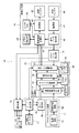
- the processor 10 includes a processor main circuit 11, an operation unit 12, a transmission data processing unit 13, and a video transmission unit 14, and performs image processing of an endoscopic image acquired by the endoscope 1.
- the operation unit 12, the transmission data processing unit 13, and the video transmission unit 14 may be configured to be built in the processor or configured as external units. Details of each component in the processor 10 will be described in detail with reference to FIG.
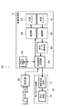
- the monitor 20 includes a video reception unit 21, an operation unit 22, and a monitor main circuit 23, and displays a video signal received from the processor 10 side on the display unit.
- the video receiving unit 21 and the operation unit 22 may be configured to be built in the monitor 20 or configured as external units. Details of each component of the monitor 20 will be described in detail with reference to FIG.
- the wireless video transmission system 100 shown in FIG. 1 detects the deterioration of the wireless communication status while transmitting the endoscope image from the processor 10 to the monitor 20 by wireless communication.
- the color data in the video signal is edited in accordance with the characteristics of the endoscope image being transmitted.
- the wireless video transmission system 100 suppresses the amount of data to be transmitted / received depending on the status of wireless communication, and continues to transmit the video signal.
- FIG. 2 is a block diagram of the processor according to the present embodiment.
- the processor 10 illustrated in FIG. 2 includes an operation unit 12, a mode setting unit 16, a mode display unit 18, a memory 17, a processor main circuit 11, a transmission data processing unit 13, a video transmission unit 14, and an error rate detection unit 15.
- the processor main circuit 11 of the processor 10 includes an imaging circuit 51 and an image processing circuit 52.
- the processor main circuit 11 performs image processing in the image processing circuit 52 on the endoscopic image input from the imaging circuit 51 provided at the distal end of the insertion portion of the endoscope 1.
- the processor main circuit 11 has color signal generation means for generating a color signal for each of a plurality of color signals for generating an image.
- the operation unit 12 accepts various settings related to wireless communication and a diagnostic mode based on an input operation by a user of the wireless video transmission system 100, and displays setting contents and a communication state.
- the diagnostic mode represents the type of image output from the processor main circuit 11 of FIG. 2, for example, a normal mode representing a normal endoscope observation image, or an NBI (Narrow Band Imaging) mode (narrowband light observation image) ( Special light mode) and an ultrasonic mode representing an ultrasonic observation image.
- Various settings relating to wireless communication and diagnostic mode include, for example, a scope switch, a touch panel of the processor 10 main body, a panel switch of the processor 10 main body and LED (Light Emitting Diode) display, and input from an external device via serial communication. By doing.
- the scope switch is provided so that an operator who performs endoscopic surgery or the like using the endoscope 1 can perform a setting operation from the sterilized area.
- the mode setting unit 16 stores the diagnosis mode set via the operation unit 12 in the memory 17 and causes the mode display unit 18 to output and display the set diagnosis mode. Further, the mode setting unit 16 notifies the transmission data processing unit 13 of the diagnosis mode notified from the operation unit 12.
- the transmission data processing unit 13 processes video such as an endoscopic image. Specifically, when the communication status is deteriorated, the transmission data processing unit 13 edits color data in the video data according to the diagnosis mode notified from the mode setting unit 16.
- the transmission data processing unit 13 includes an image automatic detection unit 31, a timer 32, a timing adjustment unit 33, an image multiplexing unit 34, a video memory 35, a memory 36, and a color data editing unit 37.
- the diagnostic mode can be set to be automatically detected by the processor 10 via the operation unit 12.
- the automatic image detection unit 31 of the transmission data processing unit 13 analyzes the video input from the processor main circuit 11 and determines the diagnosis mode.
- the diagnosis mode determination method will be described in detail later with reference to FIG. Furthermore, the image automatic detection unit 31 performs chattering processing using the timer 32 so that the diagnostic mode is not frequently switched by the automatic detection processing of the diagnostic mode.
- the timing adjustment unit 33 synchronizes the video input from the processor main circuit 11 with the OSD (On-Screen Display) image input from the mode display unit 18.
- OSD On-Screen Display
- the image multiplexing unit 34 multiplexes the video synchronized with the timing adjustment unit 33 and the OSD image.
- the memory 35 of the transmission data processing unit 13 is used to temporarily store an image for multiplexing processing.
- the color data editing unit 37 refers to the editing table 38 of the memory 36, and among the video data input from the processor main circuit 11 according to the communication status, the color data The amount of data is edited according to the diagnosis mode, and the amount of data transmitted to and received from the monitor 20 is reduced. In the embodiment, the ratio of the color data is changed according to the error rate. The deterioration of the communication status is determined based on a notification from an error rate detection unit 15 described later.
- the color data editing unit 37 edits the color data according to the diagnostic mode, and the video transmission unit 14 edits the video signal and the video signal in any ratio. Outputs information indicating whether or not A specific method for editing color data will be described in detail with reference to FIGS.
- the video transmission unit 14 includes a wireless communication management unit 41, a modulation unit 42, a memory 43, a video memory 44, a transmission antenna 45, a reception antenna 46, a demodulation unit 47, and a reception data analysis unit 48.
- the video transmission unit 14 performs necessary processing on the video signal in which necessary color data has been edited by the transmission data processing unit 13 and transmits the video signal wirelessly.
- the video transmission unit 14 receives a radio signal from the monitor 20 for the transmitted video signal and performs necessary processing.
- the wireless communication management unit 41 manages wireless communication with the monitor 20 according to a communication method set via the operation unit 12. Specifically, the wireless communication management unit 41 executes wireless connection (link) processing and transaction (retransmission control) processing. Information necessary for wireless communication, for example, information such as the MAC address (Media Access Control address) of the monitor 20 that is the connection destination is stored in the memory 43.
- wireless modulation schemes such as QAM (Quadrature Amplitude Modulation) and QPSK (Quadrature Phase Shift Keying), and wireless transmission schemes such as polarization scheme and MIMO (Multiple Input Multiple Output) are particularly specified. Any method can be adopted. In addition, there are also methods for avoiding errors when a wireless communication error occurs, such as frequency band change, transmission method change, retransmission control, etc., but there is no particular limitation, and any method can be adopted.
- the modulation unit 42 modulates the video signal input from the transmission data processing unit 13.
- the video memory 44 is used to store a video when the modulation unit 42 executes a modulation process.
- the transmission antenna 45 transmits the modulation signal input from the modulation unit 42 to the outside as a radio signal. In this way, the video signal for the endoscopic image is transmitted to the monitor 20 in FIG.
- the monitor 20 receives the radio signal from the processor 10, the monitor 20 returns the packet including the error rate to the processor 10.
- the receiving antenna 46 receives the radio signal transmitted from the monitor 20 in this way.
- the demodulator 47 demodulates the radio signal received by the receiving antenna 46.
- the reception data analysis unit 48 analyzes the reception data obtained by demodulation, and notifies each unit such as the wireless communication management unit 41 and the error rate detection unit 15 of necessary information.
- the information notified to the wireless communication management unit 41 is information necessary for maintaining wireless communication with the monitor 20, and since this is a known technique, a detailed description thereof is omitted here.
- the error rate detector 15 is notified of the detected error rate.
- the error rate detection unit 15 needs to notify the error rate to the color data editing unit 37 of the transmission data processing unit 13 by comparing the error rate notified from the reception data analysis unit 48 of the video transmission unit 14 with a predetermined threshold. It is determined whether or not there is. When it is determined that the error rate needs to be notified, the error rate detection unit 15 notifies the color data editing unit 37. When the mode display unit 18 has a function of displaying a communication state such as an error rate, the error rate detection unit 15 may instruct the operation unit 12 to display on the mode display unit 18.
- FIG. 3 is a block diagram of the monitor according to the present embodiment.
- the monitor 20 shown in FIG. 3 includes a video receiving unit 21, a monitor main circuit 23, and an operation unit 22, receives a video signal transmitted from the processor 10 through wireless communication, and displays an endoscopic image or the like on the screen. .
- the operation unit 22 receives various settings related to wireless communication with the processor 10 based on an input operation by a user of the wireless video transmission system 100, and displays the set contents.
- Various settings relating to wireless communication are performed, for example, by accepting input from an external device via a touch panel of the monitor 20 main body, similarly a panel switch and LED display of the monitor 20 main body, and serial communication.
- the monitor main circuit 23 has an image processing circuit 71 and a display circuit 72, performs image processing on the video signal received from the processor 10 via the video receiving unit 21 in the image processing circuit 71, and the display circuit 72 Display on the screen.
- the video reception unit 21 includes a reception antenna 61, a demodulation unit 62, a reception data analysis unit 63, a wireless communication management unit 64, a memory 65, a modulation unit 66, and a transmission antenna 67.
- the video receiving unit 21 receives a video signal and the like from the processor 10 and performs necessary processing, and also performs necessary processing on the signal transmitted to the processor 10 to transmit the signal wirelessly.
- the receiving antenna 61 receives a radio signal transmitted from the processor 10 in FIG.
- the demodulator 62 demodulates the radio signal received by the receiving antenna 61.
- the received data analysis unit 63 analyzes the data obtained by demodulation and calculates an error rate.
- the error rate is obtained, for example, by measuring the baud rate.
- the received data analysis unit 63 edits the video signal of the received signals into a video format that can be received by the monitor main circuit 23 and outputs the edited video format to the monitor main circuit 23.
- a video format editing method will be described with reference to FIG.
- the wireless communication management unit 64 manages wireless communication with the processor 10 using a communication method set via the operation unit 22. Specifically, the wireless communication management unit 64 executes wireless connection (link) processing and transaction (retransmission control) processing. Information necessary for wireless communication, for example, information such as the MAC address of the processor 10 that is the connection destination is stored in the memory 65.
- the modulation unit 66 modulates a signal to be transmitted to the processor 10.
- the transmission antenna 67 transmits the modulation signal input from the modulation unit 66 to the outside as a radio signal.
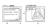
- the setting menu 82 is superimposed and displayed on the screen of the monitor 20 in the endoscopic image 81 as in the example of the menu screen shown in FIG.
- the diagnostic mode 83 set in the endoscopic image 81 is displayed in OSD. The user can set the diagnostic mode through the screen of the monitor 20 displaying the endoscopic image 81 even during endoscopic surgery or the like.
- the processor 10 determines the data amount accordingly. And the communication is continued by changing the color data ratio of the video signal.
- the processor 10 that is the transmission source of the video signal detects the deterioration of the communication status from the packet that notifies the error rate from the monitor 20.
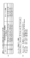
- FIG. 5 is a diagram illustrating a format example of a packet for notifying an error rate.
- a predetermined field of a packet received by the processor 10 from the monitor 20 includes data indicating an error rate.
- FIG. 5 illustrates a case where data representing an error rate is stored in the field “Error Rate”. In the example shown in the figure, when data “00h” is stored, the error rate is 0%, data “32h” has an error rate of 50%, and data “4Bh” has an error rate of 75%. It represents that.
- the value stored in the field “Error Rate” several values may be prepared as illustrated in FIG. In this case, when the error rate value measured by the wireless communication management unit 64 of the monitor 20 exceeds the prepared value, the maximum value of the prepared values is stored in the field and notified to the processor 10. Alternatively, the error rate value measured by the wireless communication management unit 64 of the monitor 20 may be stored in the field as it is and notified to the processor 10.
- the received data analysis unit 48 of the processor 10 notifies the error rate detection unit 15 of the value stored in the field “Error Rate” of the received packet.
- the error rate detection unit 15 notifies the error rate to the color data editing unit 37 of the transmission data processing unit 13.
- 50% and 75% are set as the threshold values.
- the color data editing unit 37 determines a location to be referred to in the editing table 38 based on the error rate notified from the error rate detection unit 15.
- the processor 10 changes the ratio of the color data transmitted to the monitor 20 to a value corresponding to the transmission rate.
- the endoscopic image is selected according to the diagnostic mode, that is, according to what kind of observation image the endoscopic image is.
- the amount of data is reduced by changing the color data ratio in a way that reduces the effect on image quality.
- a method of changing the ratio of the color data there is a first method by thinning out bits and a second method by thinning out pixels. Next, a method for changing the ratio of these color data will be specifically described with reference to FIGS.
- FIG. 6 is a diagram showing a configuration example of the color data editing table 38 used when the bit thinning method is used. With reference to FIG. 6, one method for setting the ratio of color data according to the error rate and the diagnostic mode will be described.
- the edit table 38 shows that the diagnostic mode is “normal mode”, “NBI mode”, and “0” for the error rates “0 percent”, “50 percent”, and “75 percent”, respectively. It is defined how to thin out bits of color data depending on which of the “ultrasonic mode” is set.
- the error rate has changed from 0 percent to more than 50 percent when transmitting an endoscopic image in the normal mode.
- the error rate is 0%
- the color data ratio is determined by referring to the first row L1 and the first column C1 in the editing table 38.
- bit thinning is not performed, and all (100 percent) bits of luminance Y and color differences Pb and Pr are transmitted among the bits of the video signal input from the processor main circuit 11.
- the error rate exceeds 50%, the reference location of the edit table 38 is changed to the second row L2 and the first column C1.
- the bits are thinned out, and among the bits of the video signal input from the processor main circuit 11, the luminance Y bit is reduced to 80%, and the color difference Pb and color difference Pr bits are reduced to 25% and 45%, respectively. To do.
- the corresponding rows L1 to L3 and columns C1 to C3 of the editing table 38 are referred to, and the luminance Y, color differences Pb, Pr are used at the ratios defined in the reference locations. Thinning out the bits.
- the ratio is set.
- information that prioritizes information according to the diagnostic mode that is, the characteristics of the observation image, is set for each of the plurality of color signals in the editing table 38.
- the image in the ultrasonic mode is basically a monochrome image, even if the information on the color differences Pb and Pr is cut to some extent, it is difficult for a user such as an operator to observe the image.
- the ratio of the color data is set so that Pr information having a strong correlation with red color is preferentially transmitted so that troubles in image observation are less likely to occur. It is set higher than Pb.
- the ratio of color data is set so that Pb is higher than Pr so that information of Pb having a strong correlation with blue is preferentially transmitted.
- FIG. 6 shows an example of a method for setting the ratio of the luminance Y, the color differences Pb, and Pr, and is not limited to this.
- the ratio may be determined as appropriate according to the error rate according to the characteristics of the image in each diagnosis mode.
- the present invention is not limited to this.
- the color data ratio may be defined for different error rates, or the color data ratio may be defined for other diagnostic modes.
- the error rate value does not need to be 0 percent, 50 percent, and 75 percent, and other values may be set. Furthermore, it is not always necessary to define all diagnostic modes and error rates shown in FIG.
- the color data editing unit 37 of the transmission data processing unit 13 edits the color data in accordance with the definition of the editing table 38 shown in FIG. 6, and the edited video signal is transmitted to the video transmission unit. 14
- the color data editing unit 37 generates format information indicating what ratio the color data of the video signal is edited, and passes the format information to the video transmission unit 14.
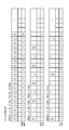
- FIG. 7 is a diagram illustrating an example of signals transmitted by the processor 10 when color data is edited based on the editing table 38 of FIG. Referring to FIG. 7, when editing the ratio of color data according to the definition of edit table 38 of FIG. 6, how processor 10 is editing the ratio of the video signal and the color data of the video signal. A method for transmitting information representing the above to the monitor 20 will be specifically described.
- FIG. 7A illustrates a signal output from the transmission data processing unit 13 of the processor 10 to the video transmission unit 14.
- a configuration example of a signal corresponding to each error rate when the diagnosis mode is the “normal mode” is shown.
- a signal transmitted to the monitor 20 via the video transmission unit 14 of the processor 10 represents format information indicating a ratio of color data, that is, a video signal (a) representing an endoscopic image and color data of the video signal. Signal.
- the video signal a includes bits thinned out in accordance with the definition of the editing table 38 in FIG.
- FIG. 7A shows a video signal edited according to row L1 and columns C1 to C3 in the editing table 38 of FIG.
- FIG. 7A illustrates the video signal a corresponding to each error rate when the diagnostic mode is set to “normal mode”, but the error rate is 0 for diagnostic modes other than the normal mode.
- the number of bits in the case of percentage is reduced according to the thinning rate defined in the reference location in the editing table 38 of FIG. A known technique is used as a method of thinning out the bits.
- the format information (2) information indicating how many bits of the luminance Y, color difference Pb, and Pr are thinned out of the video signal a is stored. For example, when the error rate is 50% in the normal mode, information indicating that the data thinned out to the luminance Y of 80%, the color difference Pb of 25%, and the color difference Pr of 45% is transmitted as the video signal a is stored.
- the format information is transmitted in the format shown in FIG.
- the first field “Operation Mode” stores a value indicating the diagnosis mode
- the subsequent fields “Y data length”, “Pb data length”, and “Pr data length” contain the data length of luminance Y, color difference Pb, and Pr, respectively.
- the data length of each color data of luminance Y and color differences Pb and Pr is set to 100 percent in the uncompressed state where the error rate is 0 percent, and how much bit length is included in the video signal a. Is expressed as a percentage.
- the format information is transmitted using, for example, a blanking period of a video frame including the video signal a.
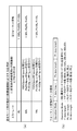
- FIG. 8 is a diagram illustrating a configuration example of the color data editing table 38 used when the pixel thinning method is used. With reference to FIG. 8, another method for setting the ratio of the color data according to the error rate and the diagnostic mode will be described.
- FIG. 8 only the edit table 38 for the normal mode is shown.
- the same value as the value in the case of thinning out the bits of FIG. 6 is set as the ratio of compressing the color data at each error rate.
- the color data is also compressed with the same value as the ratio in each error rate when bits in FIG.
- the color data of the pixels constituting each video frame is set to a predetermined ratio by not transmitting the predetermined number of pixels defined by the editing table 38 among the pixels constituting each video frame. It has been reduced.
- FIG. 8 shows an example of a pixel thinning method. Which of the luminance Y and the color differences Pb and Pr for which pixel is to be transmitted is determined at a predetermined ratio (for example, in the normal mode).
- a predetermined ratio for example, in the normal mode.
- the luminance Y can be arbitrarily set as long as 80%, the color difference Pb is 25%, and the color difference Pr is 45%.
- the edit table 38 for thinning out pixels it is possible to arbitrarily set how many diagnostic modes and error rates are defined, as in the edit table for thinning out bits in FIG. In addition, it is possible to arbitrarily set which diagnostic mode is defined and which value is set as the error rate value.
- FIG. 9 is a diagram showing an example of signals transmitted by the processor 10 when color data is edited based on the editing table 38 of FIG.
- the processor 10 edits the ratio of the video signal and the ratio of the color data of the video signal.
- a method for transmitting information indicating whether or not to the monitor 20 will be specifically described. Here, the description will focus on points different from the signal example shown in FIG.
- FIG. 9A illustrates a signal output from the transmission data processing unit 13 of the processor 10 to the video transmission unit 14.
- a signal configuration example for each error rate when the diagnosis mode is the “normal mode” is shown.
- the signal transmitted to the monitor 20 includes a video signal (referred to as b) and a signal representing format information, as in the method of thinning out the bits.
- color data of a predetermined pixel number is thinned out according to the editing table 38 of FIG.
- the format information (2) the same information as that shown in FIG. 7A is stored.
- the format of the format information is the same as the format in the case of taking a bit thinning method (FIG. 7B).
- the data lengths of Y and color differences Pb and Pr are stored. Regarding the data length of the luminance Y and the color differences Pb and Pr, here, how many pixels are included in the video signal b out of the pixels constituting one video frame is expressed as a percentage.
- the monitor 20 determines how much the luminance Y and the color differences Pb and Pr are thinned based on the received format information. To do. Then, the wireless communication management unit 64 of the video receiving unit 21 interpolates the bits or pixels that are thinned out with respect to the video signals a and b based on the ratio of the luminance Y and the color differences Pb and Pr being thinned out. To display the obtained video signal on the screen.
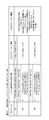
- FIG. 10 is a diagram illustrating a process of interpolating and outputting color data from a signal received from the processor 10 in the wireless communication management unit 64 of the monitor 20.
- Each column in FIG. 10 includes (1) a video signal a or b input to the wireless communication management unit 64 of the monitor 20, (2) format information input to the wireless communication management unit 64, and (3) wireless communication.
- generates is shown.
- the wireless communication management unit 64 (2)
- the video signals a and b in (1) are interpolated based on the format information received from the processor 10 and edited into a video format that can be processed by the monitor main circuit 23 in FIG.
- the output format information of (3) can be obtained by appropriately executing an interpolation process such as filling the thinned bits with “0” if the bits are thinned.
- the interpolation process such as copying the contents of the previous pixel (pixel) or filling the thinned pixel with a specific value (for example, 0) is executed as appropriate. To do.
- the automatic image detection unit 31 of the transmission data processing unit 13 may determine the diagnosis mode by analyzing the color information of the video input from the processor main circuit 11. .
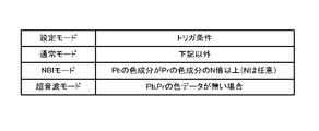
- FIG. 11 is a diagram illustrating a method of determining the diagnosis mode from the color information of the video in the image automatic detection unit 31.
- the image automatic detection unit 31 may determine that the diagnostic mode is the NBI mode when the color component of the color difference Pb is N times or more than the color component of the color difference Pr.
- the diagnostic mode is the ultrasonic mode.
- the diagnosis mode is neither the NBI mode nor the ultrasonic mode, it is determined that the normal mode is set.
- a timer is used in order to prevent frequent switching of the diagnostic mode as described with reference to FIG. It is desirable to perform the chattering process using 32.
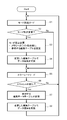
- FIG. 12 is a flowchart showing color data editing processing by the color data editing unit 37 of the processor 10 according to this embodiment.
- the color data editing unit 37 starts the wireless communication between the processor 10 and the monitor 20 and the series of processing shown in FIG. 12 is triggered by the video input from the processor main circuit 11 to the transmission data processing unit 13. To start.
- step S1 the diagnostic mode stored in the memory 17 is read via the mode setting unit 16.
- step S2 it is determined whether or not the set diagnosis mode has been changed by the operation unit 12.
- the determination in step S2 is performed based on, for example, whether or not the diagnostic mode stored in the memory 36 of the transmission data processing unit 13 matches the diagnostic mode read in step S1. If there is no change in the diagnosis mode, if necessary, the color data is edited by a method defined in a reference location set in advance in the editing table 38, and the process proceeds to step S5. If the diagnosis mode has been changed, the process proceeds to step S3.
- step S3 various settings are changed according to the diagnostic mode read in step S1. Specifically, the diagnostic mode read in step S1 is written into the memory 36 of the transmission data processing unit 13 and the reference location in the editing table 38 is changed.
- step S4 when information is read from the corresponding part of the edited editing table 38 and the color data is edited according to this information, the process proceeds to step S5.
- step S5 the error rate is read from the memory 36.
- step S6 it is determined whether or not the error rate has changed. The determination in step S6 is made based on whether or not the read error rate exceeds the threshold (whether or not it is lower), with the error rate value set in the editing table 38 as a threshold.
- the memory 36 holds the latest error rate notified from the error rate detection unit 15. If there is no change in the error rate, a video signal including color data is output to the video transmission unit 14, and the process returns to step S1. If there is a change in the error rate, the process proceeds to step S7.
- step S7 the reference location in the editing table 38 is changed.
- step S8 when information is read from the corresponding part of the editing table 38 and color data is edited according to the information, a video signal including the color data is output to the video transmission unit 14, and the process returns to step S1.
- the color data editing unit 37 is referred to when there is a change in the set diagnostic mode or when the error rate notified from the monitor 20 changes beyond a predetermined threshold.
- the reference location of the edit table 38 to be changed is changed. Then, the color data is edited by the method defined in the changed reference location.
- FIG. 12 shows processing when the automatic detection function of the diagnostic mode by the image automatic detection unit 31 is not executed.
- the color data editing unit 37 receives the notification of the diagnosis mode from the automatic image detection unit 31 in step S1 of FIG. Run in the same way as
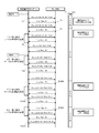
- FIG. 13 is a diagram showing a specific sequence example when the endoscope image is transmitted and received between the processor 10 and the monitor 20 by the above-described method.
- the transmission rate is 100%, so the monitor 20 notifies the processor 10 that the error rate is 0% by the packet P1 or the like.
- the packet that the monitor 20 returns to the processor 10 for the frame with the frame number N is denoted as “packet PN”.
- the monitor 20 After the transmission rate drops to 50%, the monitor 20 notifies that the error rate is 50% for packets after the packet P2.
- the processor 10 determines that the error rate has exceeded the first threshold (50%), and changes the reference location of the editing table 38. For frames subsequent to the frame F4 after the change processing of the reference portion is completed, for example, the luminance Y is compressed to 80%, the color difference Pb is compressed to 25%, and the color difference Pr is compressed to 45% and transmitted. Similarly, while the transmission rate is 50%, the monitor 20 returns the frame for which the notification with the error rate of 50% is received.
- the processor 10 changes the reference location of the editing table 38. After the change of the reference location, for example, the brightness Y is compressed to 80%, the color difference Pb is compressed to 45%, and the color difference Pr is compressed to 25%, and the frame F101 and subsequent frames are transmitted.
- the monitor 20 notifies that the error rate is 75% after the packet P1000.
- the processor 10 determines that the error rate has exceeded the second threshold (75%), and changes the reference location of the editing table 38. For frame F1002 and subsequent frames after the reference location change processing is completed, for example, the luminance Y is compressed to 50 percent, the color difference Pb is compressed to 15 percent, and the color difference Pr is transmitted to 10 percent and transmitted.
- the monitor 20 After that, when the error in wireless communication is resolved and the transmission rate returns to 100%, the monitor 20 notifies that the error rate is 0% for packets P1999 and thereafter.
- the processor 10 When the processor 10 receives the packet P1999, the processor 10 changes the reference location of the editing table 38, assuming that the error rate falls below the first and second thresholds. After the change of the reference location, for example, all of the luminance Y and the color differences Pb and Pr are transmitted as they are (without compression), and the frames F2001 and later are transmitted.
- the color data editing of the transmission data processing unit 13 is performed when the communication status changes while transmitting a video signal by wireless communication.
- the unit 37 reduces the color data to be transmitted by a method according to the error rate and the diagnosis mode, and continues communication.
- the compression ratio of the color data is set by a method that can reduce the influence on the image quality according to the diagnostic mode, that is, according to the characteristics of the endoscopic image. For this reason, the endoscope image displayed on the monitor 20 is ensured with sufficient image quality for the user of the radio video transmission system 100 such as an operator to perform endoscopic observation.
- the present invention can be variously improved and changed without departing from the gist of the present invention.
- some components may be deleted from the overall configuration shown in each of the above-described embodiments, and different components in each embodiment may be combined as appropriate.
Landscapes
- Health & Medical Sciences (AREA)
- Life Sciences & Earth Sciences (AREA)
- Engineering & Computer Science (AREA)
- Surgery (AREA)
- Biomedical Technology (AREA)
- Heart & Thoracic Surgery (AREA)
- Biophysics (AREA)
- Nuclear Medicine, Radiotherapy & Molecular Imaging (AREA)
- Veterinary Medicine (AREA)
- Pathology (AREA)
- Radiology & Medical Imaging (AREA)
- Public Health (AREA)
- General Health & Medical Sciences (AREA)
- Physics & Mathematics (AREA)
- Medical Informatics (AREA)
- Molecular Biology (AREA)
- Animal Behavior & Ethology (AREA)
- Optics & Photonics (AREA)
- Signal Processing (AREA)
- Computer Networks & Wireless Communication (AREA)
- Multimedia (AREA)
- Endoscopes (AREA)
- Instruments For Viewing The Inside Of Hollow Bodies (AREA)
- Closed-Circuit Television Systems (AREA)
Abstract
Description
Claims (7)
- 画像を生成するための複数の色信号のうち第1の色信号を生成する第1の色信号生成手段と、
画像を生成するための複数の色信号のうち第2の色信号を生成する第2の色信号生成手段と、
前記第1の色信号と前記第2の色信号とを用いて第1の診断画像を生成するための第1の診断モードと、該第1の診断モードとは異なる第2の診断画像を生成するための第2の診断モードとを選択可能な診断モード選択手段と、
前記診断モード選択手段で選択された診断モードに応じて、前記第1の色信号生成手段及び前記第2の色信号生成手段で生成される色信号に対して情報の優位性を優先付けする優先順位決定手段と、
前記優先順位決定手段で優先付けされた優先順位に応じて前記第1の色信号生成手段で生成された前記第1の色信号及び前記第2の色信号生成手段で生成された前記第2の色信号の伝送割合を変更する伝送割合変更手段と、
前記伝送割合変更手段で変更された伝送割合に応じて、前記第1の色信号及び前記第2の色信号を伝送する色信号伝送手段と、
を具備したことを特徴とする色信号伝送装置。 - 内視鏡装置において取得した映像を変換して得られる映像信号を無線通信にて送受する無線映像伝送システムにおいて使用される送信装置であって、
無線通信の通信状況を監視する通信状況検出部と、
前記通信状況検出部において通信状況の変化を検出した場合は、前記内視鏡装置が映像を取得するときのモードに応じて、前記映像信号を編集する編集部と、
前記編集部から出力される前記映像信号を、受信装置に向けて送信する送信部と
を備えることを特徴とする送信装置。 - 通常の内視鏡診断を行うときの通常モード、特殊光による内視鏡診断を行うときの特殊光モード及び超音波による内視鏡診断を行うときの超音波モードの中から、前記内視鏡装置において設定されているモードを判定するモード判定部と、
前記通常モード、特殊光モード及び超音波モードのそれぞれについての色データの間引きの割合を表す情報を記憶する記憶部と、
を更に備え、
前記編集部は、前記映像信号を編集するときは、前記モード判定部により判定されたモードに対応する色データの間引きの割合を表す情報を前記記憶部から取得して、該取得した情報にしたがって、色データの割合を編集する
ことを特徴とする請求項2記載の送信装置。 - 前記編集部は、前記通信状況検出部において通信状況が悪化したことを検出した場合に、前記モードが通常モードであるときは、映像信号のうち、Pr成分をPb成分よりも高い割合となるように編集を行う
ことを特徴とする請求項3記載の送信装置。 - 前記編集部は、前記通信状況検出部において通信状況が悪化したことを検出した場合に、前記モードが特殊光モードであるときは、映像信号のうち、Pb成分をPr成分よりも高い割合となるように編集を行う
ことを特徴とする請求項3記載の送信装置。 - 前記編集部は、前記通信状況検出部において通信状況が悪化したことを検出した場合に、前記モードが超音波モードであるときは、映像信号のうち、Y成分が高い割合となるように編集を行う
ことを特徴とする請求項3記載の送信装置。 - 内視鏡装置において取得した映像を変換して得られる映像信号を無線通信にて送信する送信装置と、該送信装置から受信した映像信号を表示する表示部を有する受信装置とを有する無線映像伝送システムであって、
前記送信装置は、
無線通信の通信状況を監視する通信状況検出部と、
前記通信状況検出部において通信状況の変化を検出した場合は、前記内視鏡装置が映像を取得するときのモードに応じて、前記映像信号を編集する編集部と、
前記編集部から出力される前記映像信号を、受信装置に向けて送信する送信部と
を備え、
前記受信装置は、
前記送信装置から受信した映像信号を編集して前記表示部に表示するフォーマットに編集するとともに、通信状況を検知する解析部と
を備えることを特徴とする無線映像伝送システム。
Priority Applications (4)
| Application Number | Priority Date | Filing Date | Title |
|---|---|---|---|
| EP12848491.2A EP2679143B1 (en) | 2011-11-11 | 2012-11-07 | Wireless image transmission system |
| JP2013528155A JP5362156B1 (ja) | 2011-11-11 | 2012-11-07 | 色信号伝送装置、無線映像伝送システム及び送信装置 |
| CN201280018803.9A CN103476324B (zh) | 2011-11-11 | 2012-11-07 | 色彩信号传输装置、无线影像传输系统以及发送装置 |
| US13/922,730 US8957952B2 (en) | 2011-11-11 | 2013-06-20 | Color signal transmission device, wireless image transmission system, and transmitter |
Applications Claiming Priority (2)
| Application Number | Priority Date | Filing Date | Title |
|---|---|---|---|
| JP2011-247913 | 2011-11-11 | ||
| JP2011247913 | 2011-11-11 |
Related Child Applications (1)
| Application Number | Title | Priority Date | Filing Date |
|---|---|---|---|
| US13/922,730 Continuation US8957952B2 (en) | 2011-11-11 | 2013-06-20 | Color signal transmission device, wireless image transmission system, and transmitter |
Publications (1)
| Publication Number | Publication Date |
|---|---|
| WO2013069691A1 true WO2013069691A1 (ja) | 2013-05-16 |
Family
ID=48290065
Family Applications (1)
| Application Number | Title | Priority Date | Filing Date |
|---|---|---|---|
| PCT/JP2012/078860 Ceased WO2013069691A1 (ja) | 2011-11-11 | 2012-11-07 | 色信号伝送装置、無線映像伝送システム及び送信装置 |
Country Status (5)
| Country | Link |
|---|---|
| US (1) | US8957952B2 (ja) |
| EP (1) | EP2679143B1 (ja) |
| JP (1) | JP5362156B1 (ja) |
| CN (1) | CN103476324B (ja) |
| WO (1) | WO2013069691A1 (ja) |
Cited By (7)
| Publication number | Priority date | Publication date | Assignee | Title |
|---|---|---|---|---|
| WO2015190443A1 (ja) * | 2014-06-13 | 2015-12-17 | オリンパス株式会社 | 固体撮像装置及び撮像方法 |
| CN105744241A (zh) * | 2016-04-07 | 2016-07-06 | 珠海格力电器股份有限公司 | 一种拍摄方法、拍摄装置及电子设备 |
| JP2016123825A (ja) * | 2015-01-08 | 2016-07-11 | オリンパス株式会社 | 内視鏡システム |
| CN107076937A (zh) * | 2014-09-23 | 2017-08-18 | 康宁光电通信有限责任公司 | 具有磁性附件的光学连接器和互补光学插孔 |
| JP2019098048A (ja) * | 2017-12-07 | 2019-06-24 | ソニー・オリンパスメディカルソリューションズ株式会社 | 医療用内視鏡装置、および医療用観察システム |
| WO2020250776A1 (ja) * | 2019-06-11 | 2020-12-17 | ソニー株式会社 | 医療用システム、通信方法、撮影装置、情報処理装置、及び、内視鏡システム |
| US11245884B2 (en) | 2017-01-06 | 2022-02-08 | Sony Corporation | Control apparatus, control system, and control method for transmission of a biological image |
Families Citing this family (17)
| Publication number | Priority date | Publication date | Assignee | Title |
|---|---|---|---|---|
| JP6177087B2 (ja) * | 2013-10-16 | 2017-08-09 | オリンパス株式会社 | 体外端末、カプセル内視鏡システム、カプセル内視鏡制御方法およびプログラム |
| CN105765958B (zh) * | 2014-02-10 | 2018-11-02 | 奥林巴斯株式会社 | 无线图像传送系统以及无线图像传送方法 |
| JP2015160098A (ja) * | 2014-02-28 | 2015-09-07 | 富士フイルム株式会社 | 内視鏡システム |
| JP2016087248A (ja) * | 2014-11-07 | 2016-05-23 | ソニー株式会社 | 観察装置及び観察システム |
| JP6062112B2 (ja) * | 2015-01-05 | 2017-01-18 | オリンパス株式会社 | 内視鏡システム |
| CN106999022A (zh) * | 2015-01-22 | 2017-08-01 | 奥林巴斯株式会社 | 内窥镜系统 |
| CN110325098A (zh) | 2016-11-28 | 2019-10-11 | 适内有限责任公司 | 具有可分离一次性轴的内窥镜 |
| JP7237095B2 (ja) * | 2019-01-22 | 2023-03-10 | オリンパス株式会社 | ビデオプロセッサ、内視鏡システムおよび内視鏡装置の画像処理装置の作動方法 |
| JP7187585B2 (ja) * | 2019-01-31 | 2022-12-12 | オリンパス株式会社 | ビデオプロセッサ、内視鏡システム、内視鏡および画像処理方法 |
| USD1018844S1 (en) | 2020-01-09 | 2024-03-19 | Adaptivendo Llc | Endoscope handle |
| WO2021172131A1 (ja) * | 2020-02-28 | 2021-09-02 | 富士フイルム株式会社 | 内視鏡システム、及び内視鏡システムの作動方法 |
| USD1051380S1 (en) | 2020-11-17 | 2024-11-12 | Adaptivendo Llc | Endoscope handle |
| USD1031035S1 (en) | 2021-04-29 | 2024-06-11 | Adaptivendo Llc | Endoscope handle |
| USD1070082S1 (en) | 2021-04-29 | 2025-04-08 | Adaptivendo Llc | Endoscope handle |
| USD1066659S1 (en) | 2021-09-24 | 2025-03-11 | Adaptivendo Llc | Endoscope handle |
| CN114337865A (zh) * | 2021-12-28 | 2022-04-12 | 重庆金山医疗技术研究院有限公司 | 胶囊内镜通信检测设备和方法 |
| CN115670349B (zh) * | 2022-11-11 | 2026-01-02 | 杭州海康慧影科技有限公司 | 一种医用内窥镜系统的自检方法、装置及医用内窥镜系统 |
Citations (7)
| Publication number | Priority date | Publication date | Assignee | Title |
|---|---|---|---|---|
| JPH03118025A (ja) * | 1989-10-02 | 1991-05-20 | Olympus Optical Co Ltd | 内視鏡画像データ圧縮装置 |
| JPH03121036A (ja) * | 1989-10-05 | 1991-05-23 | Olympus Optical Co Ltd | 内視鏡画像データ記録再生装置 |
| JP2005058576A (ja) * | 2003-08-19 | 2005-03-10 | Shimadzu Corp | 超音波診断装置 |
| JP2006122586A (ja) | 2004-11-01 | 2006-05-18 | Olympus Corp | カプセル型超音波診断装置 |
| JP2008023101A (ja) * | 2006-07-21 | 2008-02-07 | Fujifilm Corp | 電子内視鏡システム |
| JP2009172280A (ja) | 2008-01-28 | 2009-08-06 | Olympus Corp | 内視鏡装置 |
| JP2011041758A (ja) | 2009-08-24 | 2011-03-03 | Olympus Medical Systems Corp | 医療機器 |
Family Cites Families (30)
| Publication number | Priority date | Publication date | Assignee | Title |
|---|---|---|---|---|
| US5331551A (en) | 1989-10-02 | 1994-07-19 | Olympus Optical Co., Ltd. | Endoscope image recording system for compressing and recording endoscope image data |
| US5209220A (en) | 1989-10-05 | 1993-05-11 | Olympus Optical Co., Ltd. | Endoscope image data compressing apparatus |
| US5408263A (en) * | 1992-06-16 | 1995-04-18 | Olympus Optical Co., Ltd. | Electronic endoscope apparatus |
| JPH07264621A (ja) * | 1994-03-18 | 1995-10-13 | Sony Corp | 映像信号混合回路 |
| JP3902806B2 (ja) * | 1996-01-26 | 2007-04-11 | キヤノン株式会社 | ビデオカメラ |
| US7030904B2 (en) * | 1997-10-06 | 2006-04-18 | Micro-Medical Devices, Inc. | Reduced area imaging device incorporated within wireless endoscopic devices |
| US7260826B2 (en) * | 2000-05-31 | 2007-08-21 | Microsoft Corporation | Resource allocation in multi-stream IP network for optimized quality of service |
| US7197329B2 (en) * | 2002-03-25 | 2007-03-27 | Canon Kabushiki Kaisha | Wireless communication apparatus, cordless telephone, display operation control method, program, and storage medium |
| US20030216626A1 (en) * | 2002-03-28 | 2003-11-20 | Fuji Photo Film Co., Ltd. | Fluorescence judging method and apparatus |
| US7179221B2 (en) * | 2002-03-28 | 2007-02-20 | Fuji Photo Film Co., Ltd. | Endoscope utilizing fiduciary alignment to process image data |
| JP3792601B2 (ja) * | 2002-05-29 | 2006-07-05 | 日本放送協会 | 映像信号の圧縮装置およびその方法ならびに映像信号の復元装置およびその方法 |
| US6899672B2 (en) * | 2002-11-08 | 2005-05-31 | Scimed Life Systems, Inc. | Endoscopic imaging system including removable deflection device |
| JP4286123B2 (ja) * | 2003-12-22 | 2009-06-24 | 三洋電機株式会社 | カラー撮像素子およびカラー信号処理回路 |
| KR100583250B1 (ko) * | 2004-03-05 | 2006-05-24 | 한국전기연구원 | 개선된 영상 검출 모듈을 갖는 형광 내시경 장치 |
| JP2006109120A (ja) * | 2004-10-06 | 2006-04-20 | Funai Electric Co Ltd | 赤外線撮像装置 |
| US20060217594A1 (en) * | 2005-03-24 | 2006-09-28 | Ferguson Gary W | Endoscopy device with removable tip |
| JP2007068918A (ja) * | 2005-09-09 | 2007-03-22 | Fujifilm Corp | 超音波プローブ、および超音波診断装置 |
| US7983458B2 (en) * | 2005-09-20 | 2011-07-19 | Capso Vision, Inc. | In vivo autonomous camera with on-board data storage or digital wireless transmission in regulatory approved band |
| US20080114247A1 (en) * | 2006-11-10 | 2008-05-15 | Penrith Corporation | Transducer array imaging system |
| JP4793449B2 (ja) * | 2006-11-10 | 2011-10-12 | 三菱電機株式会社 | ネットワーク映像合成表示システム |
| US20080177140A1 (en) * | 2007-01-23 | 2008-07-24 | Xillix Technologies Corp. | Cameras for fluorescence and reflectance imaging |
| JP4936528B2 (ja) * | 2007-03-28 | 2012-05-23 | 富士フイルム株式会社 | カプセル内視鏡システム、およびカプセル内視鏡システムの作動方法 |
| JP5096090B2 (ja) * | 2007-09-19 | 2012-12-12 | オリンパスメディカルシステムズ株式会社 | 生体内画像受信装置および生体内画像取得システム |
| MX2010010292A (es) * | 2008-03-18 | 2011-01-25 | Novadaq Technologies Inc | Sistema de formacion de imagenes para la reflectancia combinada de color completo y formacion de imagenes cercanas al infrarrojo. |
| KR100902170B1 (ko) * | 2008-05-19 | 2009-06-10 | (주)펨트론 | 표면형상 측정장치 |
| JP5390942B2 (ja) * | 2009-06-03 | 2014-01-15 | 富士フイルム株式会社 | 超音波診断装置及び信号処理プログラム |
| JP5874116B2 (ja) * | 2009-07-30 | 2016-03-02 | 国立研究開発法人産業技術総合研究所 | 画像撮影装置および画像撮影方法 |
| JP2011125404A (ja) * | 2009-12-15 | 2011-06-30 | Olympus Corp | 光制御装置、制御装置、光学スコープ及び光走査型光学装置 |
| US8891610B2 (en) * | 2010-05-05 | 2014-11-18 | Samsung Electronics Co., Ltd. | Method and system for chroma partitioning and rate adaptation for uncompressed video transmission in wireless networks |
| JP5032646B2 (ja) * | 2010-11-24 | 2012-09-26 | 株式会社東芝 | 撮像装置、撮像装置の作動方法及び内視鏡装置 |
-
2012
- 2012-11-07 JP JP2013528155A patent/JP5362156B1/ja active Active
- 2012-11-07 WO PCT/JP2012/078860 patent/WO2013069691A1/ja not_active Ceased
- 2012-11-07 EP EP12848491.2A patent/EP2679143B1/en not_active Not-in-force
- 2012-11-07 CN CN201280018803.9A patent/CN103476324B/zh active Active
-
2013
- 2013-06-20 US US13/922,730 patent/US8957952B2/en active Active
Patent Citations (7)
| Publication number | Priority date | Publication date | Assignee | Title |
|---|---|---|---|---|
| JPH03118025A (ja) * | 1989-10-02 | 1991-05-20 | Olympus Optical Co Ltd | 内視鏡画像データ圧縮装置 |
| JPH03121036A (ja) * | 1989-10-05 | 1991-05-23 | Olympus Optical Co Ltd | 内視鏡画像データ記録再生装置 |
| JP2005058576A (ja) * | 2003-08-19 | 2005-03-10 | Shimadzu Corp | 超音波診断装置 |
| JP2006122586A (ja) | 2004-11-01 | 2006-05-18 | Olympus Corp | カプセル型超音波診断装置 |
| JP2008023101A (ja) * | 2006-07-21 | 2008-02-07 | Fujifilm Corp | 電子内視鏡システム |
| JP2009172280A (ja) | 2008-01-28 | 2009-08-06 | Olympus Corp | 内視鏡装置 |
| JP2011041758A (ja) | 2009-08-24 | 2011-03-03 | Olympus Medical Systems Corp | 医療機器 |
Non-Patent Citations (1)
| Title |
|---|
| See also references of EP2679143A4 |
Cited By (13)
| Publication number | Priority date | Publication date | Assignee | Title |
|---|---|---|---|---|
| JP5932173B2 (ja) * | 2014-06-13 | 2016-06-08 | オリンパス株式会社 | 固体撮像装置及び撮像方法 |
| US9661284B2 (en) | 2014-06-13 | 2017-05-23 | Olympus Corporation | Solid state imaging apparatus and imaging method |
| WO2015190443A1 (ja) * | 2014-06-13 | 2015-12-17 | オリンパス株式会社 | 固体撮像装置及び撮像方法 |
| CN107076937B (zh) * | 2014-09-23 | 2019-11-08 | 康宁光电通信有限责任公司 | 具有磁性附件的光学连接器和互补光学插孔 |
| CN107076937A (zh) * | 2014-09-23 | 2017-08-18 | 康宁光电通信有限责任公司 | 具有磁性附件的光学连接器和互补光学插孔 |
| JP2016123825A (ja) * | 2015-01-08 | 2016-07-11 | オリンパス株式会社 | 内視鏡システム |
| CN105744241A (zh) * | 2016-04-07 | 2016-07-06 | 珠海格力电器股份有限公司 | 一种拍摄方法、拍摄装置及电子设备 |
| US11245884B2 (en) | 2017-01-06 | 2022-02-08 | Sony Corporation | Control apparatus, control system, and control method for transmission of a biological image |
| JP2019098048A (ja) * | 2017-12-07 | 2019-06-24 | ソニー・オリンパスメディカルソリューションズ株式会社 | 医療用内視鏡装置、および医療用観察システム |
| JP7051408B2 (ja) | 2017-12-07 | 2022-04-11 | ソニー・オリンパスメディカルソリューションズ株式会社 | 医療用内視鏡装置、および医療用観察システム |
| US11839353B2 (en) | 2017-12-07 | 2023-12-12 | Sony Olympus Medical Solutions Inc. | Medical endoscope device and medical observation system |
| WO2020250776A1 (ja) * | 2019-06-11 | 2020-12-17 | ソニー株式会社 | 医療用システム、通信方法、撮影装置、情報処理装置、及び、内視鏡システム |
| US12274420B2 (en) | 2019-06-11 | 2025-04-15 | Sony Group Corporation | Medical system, communication method, imaging device, information processing device, and endoscope system |
Also Published As
| Publication number | Publication date |
|---|---|
| CN103476324B (zh) | 2015-09-02 |
| US8957952B2 (en) | 2015-02-17 |
| CN103476324A (zh) | 2013-12-25 |
| JP5362156B1 (ja) | 2013-12-11 |
| EP2679143A1 (en) | 2014-01-01 |
| EP2679143B1 (en) | 2017-09-27 |
| US20140002627A1 (en) | 2014-01-02 |
| EP2679143A4 (en) | 2015-07-15 |
| JPWO2013069691A1 (ja) | 2015-04-02 |
Similar Documents
| Publication | Publication Date | Title |
|---|---|---|
| JP5362156B1 (ja) | 色信号伝送装置、無線映像伝送システム及び送信装置 | |
| US8738809B2 (en) | Electronic device, display system, transmission method and display method | |
| CN103329520B (zh) | 图像处理装置 | |
| JP2013094269A (ja) | 内視鏡装置 | |
| JP4435029B2 (ja) | 内視鏡装置 | |
| JP6362116B2 (ja) | 表示装置及びその制御方法、プログラム、記憶媒体 | |
| CN102077564A (zh) | 由图像接收机和图像发送机构成的无线通信系统及其无线通信方法 | |
| WO2017086091A1 (ja) | 画像処理装置、画像処理方法およびプログラム | |
| JP5690457B1 (ja) | 無線通信システム及び通信方法 | |
| JP2014110592A (ja) | 画像処理装置 | |
| US7986920B2 (en) | Image communication apparatus | |
| JP2009172280A (ja) | 内視鏡装置 | |
| JP2006295835A (ja) | 画像伝送システム | |
| KR20070095188A (ko) | 디지털 전송 장치 | |
| JP5608109B2 (ja) | テレビジョンカメラ装置の伝送ケーブル状態表示方法 | |
| JP2011015079A (ja) | 送信装置 | |
| JP5005389B2 (ja) | リモート撮像システム | |
| JP2005197790A (ja) | 映像伝送システム | |
| JP2006304216A (ja) | 撮像制御システム | |
| JP7354884B2 (ja) | X線動画撮影システム及びx線動画撮影方法 | |
| JP2011146958A (ja) | 放送送受信装置、番組メニュー表示・生成方法 | |
| JP2007166316A (ja) | 映像表示装置及び映像表示システム | |
| JP2007235798A (ja) | 電力線通信装置 | |
| JP4709023B2 (ja) | 伝送状態表示方法 | |
| WO2017033617A1 (ja) | 動画像送受信システム |
Legal Events
| Date | Code | Title | Description |
|---|---|---|---|
| ENP | Entry into the national phase |
Ref document number: 2013528155 Country of ref document: JP Kind code of ref document: A |
|
| 121 | Ep: the epo has been informed by wipo that ep was designated in this application |
Ref document number: 12848491 Country of ref document: EP Kind code of ref document: A1 |
|
| REEP | Request for entry into the european phase |
Ref document number: 2012848491 Country of ref document: EP |
|
| WWE | Wipo information: entry into national phase |
Ref document number: 2012848491 Country of ref document: EP |
|
| NENP | Non-entry into the national phase |
Ref country code: DE |