WO2013073492A1 - 空気調和機およびリモコン - Google Patents
空気調和機およびリモコン Download PDFInfo
- Publication number
- WO2013073492A1 WO2013073492A1 PCT/JP2012/079234 JP2012079234W WO2013073492A1 WO 2013073492 A1 WO2013073492 A1 WO 2013073492A1 JP 2012079234 W JP2012079234 W JP 2012079234W WO 2013073492 A1 WO2013073492 A1 WO 2013073492A1
- Authority
- WO
- WIPO (PCT)
- Prior art keywords
- air conditioner
- sub
- machine
- main
- remote controller
- Prior art date
- Legal status (The legal status is an assumption and is not a legal conclusion. Google has not performed a legal analysis and makes no representation as to the accuracy of the status listed.)
- Ceased
Links
Images








Classifications
-
- G—PHYSICS
- G05—CONTROLLING; REGULATING
- G05D—SYSTEMS FOR CONTROLLING OR REGULATING NON-ELECTRIC VARIABLES
- G05D23/00—Control of temperature
- G05D23/19—Control of temperature characterised by the use of electric means
-
- F—MECHANICAL ENGINEERING; LIGHTING; HEATING; WEAPONS; BLASTING
- F24—HEATING; RANGES; VENTILATING
- F24F—AIR-CONDITIONING; AIR-HUMIDIFICATION; VENTILATION; USE OF AIR CURRENTS FOR SCREENING
- F24F11/00—Control or safety arrangements
- F24F11/62—Control or safety arrangements characterised by the type of control or by internal processing, e.g. using fuzzy logic, adaptive control or estimation of values
- F24F11/63—Electronic processing
- F24F11/65—Electronic processing for selecting an operating mode
-
- G—PHYSICS
- G08—SIGNALLING
- G08C—TRANSMISSION SYSTEMS FOR MEASURED VALUES, CONTROL OR SIMILAR SIGNALS
- G08C17/00—Arrangements for transmitting signals characterised by the use of a wireless electrical link
- G08C17/02—Arrangements for transmitting signals characterised by the use of a wireless electrical link using a radio link
-
- F—MECHANICAL ENGINEERING; LIGHTING; HEATING; WEAPONS; BLASTING
- F24—HEATING; RANGES; VENTILATING
- F24F—AIR-CONDITIONING; AIR-HUMIDIFICATION; VENTILATION; USE OF AIR CURRENTS FOR SCREENING
- F24F11/00—Control or safety arrangements
- F24F11/50—Control or safety arrangements characterised by user interfaces or communication
- F24F11/54—Control or safety arrangements characterised by user interfaces or communication using one central controller connected to several sub-controllers
-
- F—MECHANICAL ENGINEERING; LIGHTING; HEATING; WEAPONS; BLASTING
- F24—HEATING; RANGES; VENTILATING
- F24F—AIR-CONDITIONING; AIR-HUMIDIFICATION; VENTILATION; USE OF AIR CURRENTS FOR SCREENING
- F24F11/00—Control or safety arrangements
- F24F11/50—Control or safety arrangements characterised by user interfaces or communication
- F24F11/56—Remote control
-
- G—PHYSICS
- G08—SIGNALLING
- G08C—TRANSMISSION SYSTEMS FOR MEASURED VALUES, CONTROL OR SIMILAR SIGNALS
- G08C2201/00—Transmission systems of control signals via wireless link
- G08C2201/20—Binding and programming of remote control devices
Definitions
- the present invention relates to an air conditioner and a remote controller in which a plurality of air conditioner bodies are operated by a plurality of remote controllers.
- Patent Document 1 an air conditioner in which one air conditioner main body is operated by a plurality of remote controllers is known (see, for example, Patent Document 1).
- Patent Document 1 when one air conditioner body is operated with a plurality of infrared remote controllers and a driving operation is performed with one remote controller, driving information is transmitted to another remote controller to display the current driving situation. It is.
- Patent Document 2 Also known is an air conditioner in which a plurality of air conditioner bodies are operated by a plurality of remote controllers (see, for example, Patent Documents 2 and 3).
- Patent Document 2 when a plurality of air conditioner main bodies are installed in the same room, an air conditioner to be operated is selected and operated in order to individually operate each air conditioner main body with one remote controller. is there.
- Patent Document 3 is a multi-type air conditioner configured with a plurality of indoor units in one outdoor unit so that the operation of the air conditioner in the other room can be operated in the same manner as the air conditioner in the own room.
- a transmitter / receiver for the other room is provided in the remote controller and the air conditioner body.
- JP-A-4-273944 Japanese Patent Laid-Open No. 6-58601 JP 2004-340567 A
- air conditioners A, B, and C are air conditioners.
- the basic control contents are exactly the same except for the ability.
- RF remote controller high frequency wireless communication system remote controller
- a signal from the remote controller 1 may reach the air conditioners B and C, and the air conditioners B and C may be operated against the user's intention.
- the air conditioners that can be operated are usually limited by performing pairing settings on the air conditioner A such as the remote controller 1.
- the air conditioners B and C in other rooms can be operated with one remote controller 1.
- the air conditioner of the next room (bedroom) to be started can be started in advance, or the temperature of the air conditioner in the child room can be set, so that it is not necessary to leave the living room.
- the air conditioners can be operated with one remote controller, there is a problem that it becomes difficult to operate the air conditioner unless the operating state of the air conditioner immediately before the operation is recognized.
- the present invention has been made in view of the above, and in an air conditioner capable of operating a plurality of air conditioner bodies with a plurality of remote controllers, the operating state of the air conditioner body immediately before the operation can be recognized.
- An object is to provide an air conditioner and a remote control.
- an air conditioner according to the present invention includes a plurality of air conditioner bodies that perform air conditioning operation, a plurality of remote controllers that operate each of the air conditioner bodies,
- An air conditioner comprising: a pairing setting unit configured to pair each of the plurality of air conditioner bodies and the plurality of remote controllers, wherein the pairing setting unit includes the plurality of air conditioner bodies and the plurality of air conditioners.
- the operation of the air conditioner main body of the main machine with the remote control is performed in the main machine operation mode, and the operation of the air conditioner main body of the sub machine with the remote control is performed in the sub mode.
- the remote controller displays the operation information of all the air conditioner bodies registered as the sub machine in the respective air conditioner bodies. The driving information transmitted from the vehicle is received and acquired.
- the remote controller in the sub-unit operation mode, can operate any one of the sub-units or register all of the sub-units collectively. And can be operated.
- another air conditioner according to the present invention is characterized in that, in the above-mentioned invention, a display portion that is turned on when operated by the remote controller as the sub-machine is provided in the air conditioner body.
- the remote controller is a remote controller that performs pairing setting by a plurality of air conditioner main bodies and pairing setting means, and operates each of the plurality of air conditioner main bodies, wherein the pairing setting means A main machine registration function for registering a pair of the air conditioner main body and the remote control as a main machine among the plurality of air conditioner main bodies and the plurality of remote controls; and a main machine of the plurality of air conditioner main bodies.
- the air conditioner main body registered as a sub machine and a sub machine registration function for registering the remote controller not registered as a main machine as a sub machine, and the air conditioner registered by the sub machine registration function Operation information of the air conditioner main body registered by the sub unit registration function when moving to the setting screen for performing settings for the main body And obtaining and receiving the operation information transmitted from each of the air conditioner body.
- a plurality of air conditioner main bodies that perform air conditioning operation
- a plurality of air conditioner main bodies that perform air conditioning operation
- a plurality of remote controllers that operate each of the air conditioner main bodies
- An air conditioner comprising: a pairing setting unit configured to pair each of the plurality of air conditioner bodies and the plurality of remote controllers, wherein the pairing setting unit includes the plurality of air conditioner bodies and the plurality of air conditioners.
- the operation of the air conditioner of the main machine with the remote controller is operated in the main machine operation mode, and the operation of the air conditioner of the sub machine with the remote control is operated in the sub machine.
- the remote controller acquires operation information of all the air conditioner main bodies registered as the sub machine. For this reason, there exists an effect that the driving
- FIG. 1 is a schematic view showing an embodiment of an air conditioner according to the present invention.
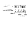
- FIG. 2 is a front view showing an example of a remote control according to the present invention.
- FIG. 3 is a block diagram of an air conditioner according to the present invention.
- FIG. 4 is a diagram illustrating an operation unit and an LED display unit of the air conditioner.
- FIG. 5A is a diagram showing a pairing setting procedure 1 in registration of the main machine.
- FIG. 5B is a diagram showing a pairing setting procedure 2 in registration of the main machine.
- FIG. 5C is a diagram showing a pairing setting procedure 3 in registration of the main machine.
- FIG. 5D is a diagram showing a pairing setting procedure 4 in registration of the main machine.
- FIG. 6 is a diagram showing a pairing setting procedure in the registration of the sub machine.
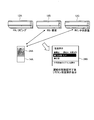
- FIG. 7 is a diagram for explaining the other room operation in the sub-machine operation mode.
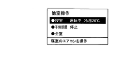
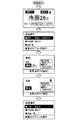
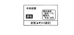
- FIG. 8A is a diagram illustrating an initial screen of the liquid crystal display unit immediately after the transition to the sub machine operation mode.
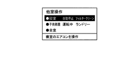
- FIG. 8B is a diagram illustrating an initial screen of the liquid crystal display unit immediately after the transition to the sub machine operation mode.
- FIG. 8C is a diagram illustrating an initial screen of the liquid crystal display unit immediately after the transition to the sub machine operation mode.
- FIG. 9 is a diagram showing screen transition of the liquid crystal display unit in the sub-machine operation mode.
- FIG. 10A is a diagram illustrating an operation content selection screen in the sub machine operation mode.
- FIG. 10B is a diagram illustrating an operation content selection screen in the sub machine operation mode.
- FIG. 10C is a diagram illustrating an operation content selection screen in the sub machine operation mode.
- FIG. 11 is a diagram illustrating a correspondence relationship between a plurality of air conditioners and a plurality of remote controllers.
- an air conditioner 10 includes a pair of indoor units (hereinafter referred to as air conditioners) 12A, 12B, and 12C arranged in a plurality of rooms RA, RB, and RC and respective indoor units not shown.
- the air conditioner main body including the outdoor unit and the remote controllers 14A, 14B, and 14C, and the functions of the air conditioners 12A, 12B, and 12C and the remote controllers 14A, 14B, and 14C are common.
- the air conditioner 10 can perform remote operation and various settings from the remote controller 14A to the air conditioners 12A to 12C, for example, using bidirectional wireless communication using an RF module.
- the remote controller 14A has a memory (not shown) that stores various operation information from the air conditioners 12A to 12C and a display unit 34A that displays the memory.
- the remote controller 14A acquires various types of driving information from the air conditioners 12A to 12C
- the remote controller 14A stores and displays the acquired driving information as new driving information and uses it for driving management and various settings.
- the remote controller 14A can wire-connect the acquired various types of operation information to a personal computer (not shown) via an external connection terminal (not shown), and can manage the operation information on the personal computer side. The same applies to the other remote controllers 12B and 12C.
- the air conditioners 12A to 12C control transmission / reception units 16A to 16C, LED display units 20A to 20C, and operation units 22A to 22C, which are RF modules that perform bidirectional wireless communication with the remote controllers 14A to 14C.
- Control units 24A to 24C are provided.
- the control units 24A to 24C control the respective units of the air conditioners 12A to 12C based on the received driving operation signals from the remote controllers 14A to 14C, and the current driving information data of the air conditioners 12A to 12C and the history of driving information.
- a memory (not shown) that calculates the operation time and power consumption (electricity cost) from the data and holds data for a certain period (for example, one month) is included.
- the LED display units 20A to 20C have main machine LEDs 26A to 26C and sub machine LEDs 28A to 28C, which are turned off when registered, and unregistered, respectively. Are controlled by the control units 24A to 24C so as to light up.
- the operation units 24A to 24C have a pairing registration button (not shown) used when registering in the remote controllers 14A to 14C as main machines and sub machines.
- the remote controllers 14A to 14C are connected to the transceiver units 16A to 16C of the air conditioners 12A to 12C.
- Liquid crystal display units 34A to 34C for displaying operation time, power consumption, etc.
- operation units 36A to 36C for operating the air conditioner
- control units 38A to 38C for controlling them.
- the transmission / reception units 30A to 30C of the remote controller are normally turned off to prevent the used battery from being consumed. Therefore, communication between the remote controller and the air conditioner is always performed after an operation signal is transmitted from the remote controller to the air conditioner to be operated.
- the air conditioner control units 24A to 24C and the remote control units 38A to 38C each include pairing setting means (not shown).
- the pairing setting means includes a main unit registration function for registering a pair of the plurality of air conditioners 12A to 12C and the plurality of remote controls 14A to 14C, for example, the air conditioner 12A and the remote controller 14A as a main unit (for own room), and other air conditioners. It has a sub machine registration function for registering the air conditioners 12B and 12C registered as main machines in the other remote controllers 14B and 14C of 12B and 12C as sub machines (for example, for other rooms).
- a pair of a plurality of air conditioners 12A to 12C and a plurality of remote controllers 14A to 14C can be registered as a main machine, and at least one remaining can be registered as a sub machine.
- the air conditioner 10 performs two-way wireless communication using the RF module between the remote controller and the air conditioner described above, the operation target device cannot be distinguished if there is another type of air conditioner nearby. Pairing settings need to be made.
- FIG. 5A A case where the air conditioner 12A is registered as a main machine in the remote controller 14A will be described as an example.
- the control unit 24A that detects that the air conditioner 12A is unregistered is used for the main machine of the LED display unit 20A as shown in FIG. 5B.
- the LED 26A and the sub-machine LED 28A are turned on to notify the user that the air conditioner is waiting for registration of the main machine, and the system automatically waits for pairing registration.
- the control unit 38A causes the liquid crystal display unit 34A to be connected to the main unit as shown in FIG. 5C. Displays the initial setting screen that guides the registration operation. Normally, the user operates according to this content. For example, after pressing a pairing registration button (not shown) provided on the operation unit 22A on the air conditioner side for 3 seconds and then simultaneously pressing the run / stop button 42A and the confirm button 44A on the remote control side, the air conditioner 12A serves as the main unit and the remote control 14A. Registered in When the registration operation is completed, the control unit 24A performs control to turn off the main machine LED 26A, and notifies the user that it has been registered as the main machine and not registered as the sub machine.
- the pairing setting will be specifically described.
- the remote control registration setting mode is set, and the air conditioner 12A A pairing display for displaying a procedure for pairing with the liquid crystal display unit 34A.
- the air conditioner 12A is displayed on the LED display unit 20A provided in the air conditioner 12A.
- the pairing execution status is indicated by a buzzer sounding, a lamp lighting, etc., and a pairing request signal on the air conditioner 12A side is sent from the transmitting / receiving unit 16A to the pairing target.
- the pairing is started.
- pairing display is displayed on the liquid crystal display unit 34A of the remote controller 14A
- start / stop button 42A and the confirm button 44A of the operation unit 36A of the remote controller 14A shown in FIG. A signal is sent from the transmitting / receiving unit 30A to the air conditioner 12A to be paired, and pairing is started. “Pairing registration in progress” is displayed on the liquid crystal display 34A of the remote controller 14A.
- communication for pairing is performed between the transmission / reception unit 30A of the remote controller 14A and the transmission / reception unit 16A of the air conditioner 12A, and it is confirmed whether the model can be registered for pairing.
- the remote controller 14A and the air conditioner 12A are paired, and a pairing completion signal indicating that the pairing is completed is transmitted from the transmitter / receiver 30A of the remote controller 14A to the controller 24A of the air conditioner 12A. At the same time, a pairing completion signal indicating that pairing is completed is transmitted from the transmission / reception unit 16A of the air conditioner 12A to the control unit 38A of the remote controller.
- an air conditioner model information request is transmitted as general-purpose data from the remote controller 14A to the air conditioner 12A.
- the air conditioner model information signal receivable from the air conditioner 12A includes a series name, a manufacturing year, a character string (up to 16 characters for the model name), an air conditioner ID (MAC address), and the like.
- the transmitting / receiving unit 16A on the air conditioner 12A side transmits a general-purpose data transmission completion signal to the remote controller 14A to notify that the transmission is successful.
- control unit 38A of the air conditioner 12A transfers the air conditioner model information to the remote controller 14A.
- the transmitting / receiving unit 30A transmits an information transfer completion signal to the air conditioner 12A to notify that the transmission is successful.
- the remote controller 14A performs the operation operation and various settings for the air conditioner 12A, and the operation status log (history) stored in the air conditioner 12A is remote controlled.
- a log can be acquired by requesting 14A.
- the pairing setting described above is the same when pairing the air conditioner 12B and the remote controller 14B, or when pairing the air conditioner 12C and the remote controller 14C. The same applies to the case of pairing the air conditioner 12A and the remote controller 14C as a sub machine.
- the control unit 24A of the air conditioner 12A is controlled by the remote controller 14B.
- the remote controller 14B receives that the air conditioner 12A is not registered as the main machine, the remote controller 14B displays the content of the registration error and the content prompting the air conditioner 12A to be registered as the main machine on the liquid crystal display unit 34B. Because it is unregistered, the user is informed that registration as a sub-device is impossible.
- the pairing registration button when the pairing registration button is pressed for a few tens of seconds, for example, the registration as the main machine and the sub machine may be deleted.
- the air conditioner to be paired first is registered as the main unit in the remote controller, and the air conditioner to be paired after this is sub-registered.
- the air conditioner to be paired is sub-registered.
- the air conditioner 12A and the remote controller 14A registered as the main machine are the air conditioner 12A registered in the remote controller 14A as the main body for the remote controller 14A, and the remote controller 14A registered in the air conditioner 12A as the main remote controller for the air conditioner 12A.
- the air conditioner 12B and the remote controller 14A registered as the remote controller 14A may be registered as the air conditioner 12B registered in the remote controller 14A as a sub-main body for the remote controller 14A and the remote controller 14A registered as the sub remote controller for the air conditioner 12B. .
- the pairing setting means included in the control units 38A to 38C of the remote controller includes main body registration means (or main body registration function) for registering one of a plurality of air conditioners as the main body, and other air conditioners.
- Sub-main body registration means (or sub-main body registration function) for registering at least one of them as a sub-main body
- the pairing setting means included in the control units 24A to 24C of the air conditioner includes a plurality of remote controllers.
- Main remote control registration means (or main remote control registration function) for registering one as a main remote control, and sub remote control registration means (or sub remote control registration function) for registering at least one of the other remote controls as a sub remote control It may be configured.
- the main body registration means registers the air conditioner in the remote control, and after the main remote control registration means registers the remote control in the air conditioner, the sub body registration means registers other air conditioners not registered in the remote control as the main body.
- the other remote controller that is not registered in the main body as the main remote controller may be registered by the sub remote controller registration means.
- the sub body may not be registered.
- the main machine and the sub machine can be easily distinguished and paired and registered.
- the sub remote controller may not be registered.
- pairing registration can be performed by easily distinguishing the main machine from the sub machine in the same manner as described above.
- the remote controller 14A of the living RA can basically perform all operations on the air conditioner 12A registered as the main machine, but is registered as a sub machine.
- the number of functions that can be operated such as switching between cooling and heating, is not possible, and only operation / stop and change of the set temperature can be operated. Or the kind is limited.
- control units 38A to 38C on the remote control side when operating the main machine or the sub machine with the remote controllers 14A to 14C, the control units 38A to 38C on the remote control side send control information signals (operation signals) to the main machine and the sub machine from the main unit.
- the control unit 24A to 24C of the main machine and the sub machine determines whether or not the operation content is directed to itself based on the recognition information included in the received control information signal. It is like that.
- control units 24A to 24C When it is determined that the operation content is directed to itself, the control units 24A to 24C perform control to execute the operation content. On the other hand, when it is determined that the operation content is not directed to itself, the control units 24A to 24C ignore the operation content.
- the remote controller 14A and another remote controller not shown in the figure are not always in a reception waiting state in order to suppress battery consumption. Therefore, as shown in FIG. 7, when the synchronization between the remote controller 14A and the main unit air conditioner 12A is not taken except when necessary, the air conditioner 12B can be changed by changing the setting content of the air conditioner 12B with another remote controller 14B not shown.
- the control information held in the control unit 24B and the control unit 38B of the remote control 14B may not match each other.
- the remote controller 14B and the air conditioner as its main unit are operated when a notification button 40B (see FIG. 2; notification switch) for confirming driving information provided on the operation unit 34B of the remote controller 14B is pressed.
- the driving information is acquired from 12B and stored and displayed as new driving information.
- the air conditioner to be operated by the remote controller transmits the driving information after receiving the driving operation signal to the remote controller.
- the remote control which received this driving information memorize stores the driving information of the air-conditioner used as driving operation object as new driving information. It should be noted that “please press the notification button” is periodically displayed on the liquid crystal display unit of the remote controller to inform the user of the contents to be operated and to prompt the user to acquire driving information.
- an air conditioner 12A to 12C may be provided with a notification display unit in which an LED is lit when operated as a main machine or a sub machine.
- This notification display section can be shared by the LED display sections 20A to 20C of FIG.
- the LED of the air conditioner of the operated sub unit may be turned on so that it can be confirmed that the sub unit has been operated.
- the user may be made aware that this operation is an error operation by turning on the LED of the main machine.
- a user who has confirmed the lighting of the LED indicating the main machine and recognized the error operation can synchronize operation information with the main machine by pressing the notification buttons 40A to 40C on the remote controller.
- the cause of the error or the result of synchronizing the operation information may be displayed on the liquid crystal display units 34A to 34C of the remote controller.
- the main unit operation mode (own room operation mode) is used when operating the air conditioner of the main unit with the remote control, and the sub unit is operated with the remote control.
- the case where the air conditioner is operated is set as a sub machine operation mode (another room operation mode). Switching between the main machine operation mode and the sub machine operation mode can be performed by operating a button on the operation unit of the remote controller.
- all air conditioners registered as sub units in the remote control can be operated, and any sub unit can be operated individually or all sub units can be operated in a batch.
- the user operates the operation unit 36A (not shown) while referring to the liquid crystal display unit 34A to select a sub machine to be operated.
- the right side of FIG. 7 illustrates a screen that enables selection of an operation target from a bedroom, a child room, or an air conditioner (sub machine) in all rooms.
- FIG. 8A to 8C show an example of an initial screen displayed on the liquid crystal display unit 34A of the remote controller 14A immediately after shifting to the sub machine operation mode.
- the operation information acquired from all the sub-machines when shifting to the sub-machine operation mode is reflected, and the current operation status of each room (each sub-machine) is displayed.
- FIG. 8A shows that the bedroom is in a cooling operation at a set temperature of 26 ° C., and the child's room is stopped. By moving the cursor in the liquid crystal display unit, it is possible to operate the air conditioner in the bedroom or to operate the air conditioners in all rooms at once (for example, start / stop operation).
- FIG. 9 is an example of the transition of the screen display of the liquid crystal display unit in the sub machine operation mode.
- the screen display of the liquid crystal display unit changes according to the operation of the operation button by the user as shown in FIG.
- the screen is switched and the operation content for the bedroom can be selected.
- FIGS. 10A to 10C show examples of selection screens for selecting the operation contents for the sub machine in the sub machine operation mode.
- FIG. 10A for example, when the air conditioner 12B in the bedroom is currently in the cooling operation, only the setting change of the set temperature in the range of 18 to 30 ° C. may be possible with the remote controller 14A.
- FIG. 10B when the air conditioner 12C in the child room is currently in automatic operation, only the setting change in the standard ⁇ 2 ° C. range may be possible with the remote controller 14A.
- FIG. 10C when the air conditioner 12C in the child room is currently stopped, only the operation can be started with the remote controller 14A, and the operation status of the air conditioner 12C can be reacquired after the operation is started. Good.
- a plurality of air conditioner bodies that perform air conditioning operation, a plurality of remote controllers that operate each of the air conditioner bodies, and the plurality of air conditioners.
- An air conditioner comprising: a main body and a pairing setting unit configured to pair each of the plurality of remote controllers, wherein the pairing setting unit includes a pair of the plurality of air conditioner bodies and the plurality of remote controllers.
- a main machine registration function for registering the air conditioner body and the remote control as a main machine, and the air conditioner body and the main machine registered as a main machine among the plurality of air conditioner bodies.
- a sub-device registration function for registering the remote controller as a sub-device, and the main device and the sub-device by the pairing setting means After the registration, the operation of operating the air conditioner main body of the main machine with the remote controller is the main machine operation mode, and the operation of operating the air conditioner main body of the sub machine with the remote control is the sub machine operation mode.
- the remote controller when the main machine operation mode is switched to the sub machine operation mode, the remote controller is operated so that the operation information of all the air conditioner bodies registered as the sub machine is transmitted from the respective air conditioner bodies. Receive and obtain information. For this reason, there exists an effect that the driving
- the air conditioner and the remote controller according to the present invention are useful for operating a plurality of air conditioners with a plurality of remote controllers, and in particular, only one of the plurality of air conditioner bodies is a main machine. It is suitable for an air conditioner that registers with the remote controller as well as at least one remaining as a sub machine.
Landscapes
- Engineering & Computer Science (AREA)
- Physics & Mathematics (AREA)
- Signal Processing (AREA)
- General Physics & Mathematics (AREA)
- Combustion & Propulsion (AREA)
- Chemical & Material Sciences (AREA)
- Mathematical Physics (AREA)
- Mechanical Engineering (AREA)
- General Engineering & Computer Science (AREA)
- Computer Networks & Wireless Communication (AREA)
- Fuzzy Systems (AREA)
- Automation & Control Theory (AREA)
- Air Conditioning Control Device (AREA)
- Selective Calling Equipment (AREA)
Abstract
Description
まず、本発明に係る空気調和機の概略構成について説明する。図1に示すように、本発明に係る空気調和機10は、複数の部屋RA、RB、RCに配置された室内機(以下、エアコン)12A、12B、12Cと図示しないそれぞれの室内機の対となる室外機とからなる空気調和機本体と、リモコン14A、14B、14Cとで構成され、各エアコン12A、12B、12Cおよび各リモコン14A、14B、14Cの機能は共通である。
次に、ペアリング設定における制御部24A~24C、38A~38C(ペアリング設定手段)の処理内容(メイン機登録機能およびサブ機登録機能)について説明する。
リモコン14Aにエアコン12Aをメイン機として登録する場合を例にとり説明する。
図5Aに示すように、メイン機が未登録の状態でエアコン12Aに電源を投入すると、未登録であることを検知した制御部24Aは、図5Bに示すようにLED表示部20Aのメイン機用LED26Aとサブ機用LED28Aとを点灯させ、エアコン側がメイン機の登録待ち状態であることをユーザーに報知して、自動的にペアリング登録待ちの状態となる。
まず、リモコン14Aの登録設定が選択された場合、あるいは、リモコン14Aの制御部38Aに搭載された図示しない不揮発性メモリにペアリング相手が記憶されていない場合は、リモコン登録設定モードとなり、エアコン12Aとペアリングを行う際の手順を表示するペアリング表示を液晶表示部34Aにする。同様に、エアコン12Aもペアリング登録がない場合は、エアコン12Aに備えられたLED表示部20Aで表示される。操作者がエアコン12Aにある図示しないペアリング登録ボタンを押下すると、ペアリング実行状態をブザーの鳴動、ランプの点灯等で示し、エアコン12A側のペアリング要求信号が送受信部16Aからペアリング対象となるリモコンに送られて、ペアリングが開始される。
次に、例えばメイン機として登録済みのエアコン12Aをサブ機として別のリモコン14Cに登録する場合には、図6に示すように、このリモコン14Cを操作して液晶表示部34Cに他室のエアコンの登録操作を案内する初期設定画面を表示させる。この表示内容に従って、例えば、エアコン側の操作部22Aのペアリング登録ボタンを3秒押した後、リモコン側の運転/停止ボタン42Aと確定ボタン44Aを同時に押すと、エアコン12Aがサブ機としてリモコン14Cに登録される。登録が認識されると制御部24Aはサブ機用LED28Aを消灯させる制御を行い、メイン機、サブ機として登録済みであることをユーザーに報知する。なお、このエアコン12Aがさらに別のリモコンにサブ機として登録可能であることは言うまでもない。
次に、ペアリング設定後の操作について説明する。
まず、本実施例では、制御部24A~24C、38A~38C(ペアリング設定手段)によるメイン機およびサブ機の登録後におけるリモコンからのサブ機に対する操作可能な機能の数を、メイン機に対する操作可能な機能の数よりも少なくしている。
次に、サブ機操作モード時の操作について説明する。
12A、12B、12C エアコン(室内機)
14A、14B、14C リモコン
16A、16B、16C 送受信部(エアコン側)
20A、20B、20C LED表示部
22A、22B、22C 操作部(エアコン側)
24A、24B、24C 制御部(エアコン側、ペアリング設定手段)
26A、26B、26C メイン機用LED
28A、28B、28C サブ機用LED
30A、30B、30C 送受信部(リモコン側)
34A、34B、34C 液晶表示部
36A、36B、36C 操作部(リモコン側)
38A、38B、38C 制御部(リモコン側、ペアリング設定手段)
40A、40B、40C お知らせボタン(運転情報確認ボタン)
42A、42B、42C 運転/停止ボタン
44A、44B、44C 確定ボタン
Claims (4)
- 空調運転を行う複数の空気調和機本体と、前記空気調和機本体それぞれを運転操作する複数のリモコンと、前記複数の空気調和機本体と前記複数のリモコンとをそれぞれペアリング設定するペアリング設定手段とを備える空気調和機であって、
前記ペアリング設定手段は、前記複数の空気調和機本体と前記複数のリモコンのうちの一対の前記空気調和機本体と前記リモコンをメイン機として登録するメイン機登録機能と、前記複数の空気調和機本体のうちのメイン機として登録されている前記空気調和機本体とメイン機として登録されていない前記リモコンをサブ機として登録するサブ機登録機能とを有するものであり、
前記ペアリング設定手段による前記メイン機および前記サブ機の登録後において、前記リモコンで前記メイン機の空気調和機本体を運転操作する場合をメイン機操作モード、前記リモコンで前記サブ機の空気調和機本体を運転操作する場合をサブ機操作モードとする場合に、メイン機操作モードからサブ機操作モードに切り換えたとき、前記リモコンは前記サブ機として登録してある全ての前記空気調和機本体の運転情報をそれぞれの空気調和機本体から送信される運転情報を受信して取得することを特徴とする空気調和機。 - サブ機操作モードにおいて、前記リモコンは任意の一つの前記サブ機を操作可能または前記サブ機として登録してある全てを一括して操作可能であることを特徴とする請求項1に記載の空気調和機。
- 前記サブ機としたリモコンで操作された場合に点灯する表示部を前記空気調和機本体に設けたことを特徴とする請求項1または2に記載の空気調和機。
- 複数の空気調和機本体とペアリング設定手段によりペアリング設定を行ない、前記複数の空気調和機本体をそれぞれ運転操作するリモコンであって、
前記ペアリング設定手段は、前記複数の空気調和機本体と前記複数のリモコンのうちの一対の前記空気調和機本体と前記リモコンをメイン機として登録するメイン機登録機能と、前記複数の空気調和機本体のうちのメイン機として登録されている前記空気調和機本体とメイン機として登録されていない前記リモコンをサブ機として登録するサブ機登録機能とを有するものであり、
前記サブ機登録機能により登録された前記空気調和機本体に対する設定を行なう設定画面に移行する際、前記サブ機登録機能により登録されている前記空気調和機本体の運転情報をそれぞれの空気調和機本体から送信される運転情報を受信して取得することを特徴とするリモコン。
Priority Applications (4)
| Application Number | Priority Date | Filing Date | Title |
|---|---|---|---|
| EP12849491.1A EP2782359B1 (en) | 2011-11-16 | 2012-11-12 | Air conditioner and remote control |
| AU2012337875A AU2012337875B2 (en) | 2011-11-16 | 2012-11-12 | Air conditioner and remote control |
| US14/359,077 US20140324231A1 (en) | 2011-11-16 | 2012-11-12 | Air conditioning system and remote controller |
| CN201280056651.1A CN103931208B (zh) | 2011-11-16 | 2012-11-12 | 空调机及遥控器 |
Applications Claiming Priority (2)
| Application Number | Priority Date | Filing Date | Title |
|---|---|---|---|
| JP2011251161A JP5278524B2 (ja) | 2011-11-16 | 2011-11-16 | 空気調和機およびリモコン |
| JP2011-251161 | 2011-11-16 |
Publications (1)
| Publication Number | Publication Date |
|---|---|
| WO2013073492A1 true WO2013073492A1 (ja) | 2013-05-23 |
Family
ID=48429551
Family Applications (1)
| Application Number | Title | Priority Date | Filing Date |
|---|---|---|---|
| PCT/JP2012/079234 Ceased WO2013073492A1 (ja) | 2011-11-16 | 2012-11-12 | 空気調和機およびリモコン |
Country Status (6)
| Country | Link |
|---|---|
| US (1) | US20140324231A1 (ja) |
| EP (1) | EP2782359B1 (ja) |
| JP (1) | JP5278524B2 (ja) |
| CN (1) | CN103931208B (ja) |
| AU (1) | AU2012337875B2 (ja) |
| WO (1) | WO2013073492A1 (ja) |
Cited By (2)
| Publication number | Priority date | Publication date | Assignee | Title |
|---|---|---|---|---|
| CN105757918A (zh) * | 2014-12-17 | 2016-07-13 | 张庆彬 | 一种便于老人或儿童使用的空调 |
| CN105793651A (zh) * | 2013-11-29 | 2016-07-20 | 大金工业株式会社 | 空调系统 |
Families Citing this family (21)
| Publication number | Priority date | Publication date | Assignee | Title |
|---|---|---|---|---|
| JP6183181B2 (ja) * | 2013-11-28 | 2017-08-23 | 株式会社富士通ゼネラル | 空気調和機 |
| JP6206135B2 (ja) * | 2013-11-28 | 2017-10-04 | 株式会社富士通ゼネラル | 空気調和機 |
| CN104165437B (zh) * | 2014-07-30 | 2017-02-08 | 广东美的集团芜湖制冷设备有限公司 | 空调器运行参数调整方法和系统 |
| US10082309B2 (en) * | 2015-01-19 | 2018-09-25 | Lennox Industries Inc. | Server integration with a heating, ventilation, and air conditioning system |
| JP2017096531A (ja) * | 2015-11-20 | 2017-06-01 | 三菱重工業株式会社 | 空気調和システム、及びその制御方法並びにプログラム |
| CN105551217B (zh) * | 2015-12-17 | 2021-07-16 | 杭州巨峰科技有限公司 | 一种无线遥控控制协议和无线遥控系统 |
| US10697659B2 (en) | 2016-02-12 | 2020-06-30 | Mitsubishi Electric Corporation | Air-conditioning control system and remote control device |
| US10907851B2 (en) * | 2016-09-26 | 2021-02-02 | Mitsubishi Electric Corporation | Air-conditioning remote controller |
| JP6895110B2 (ja) * | 2017-03-17 | 2021-06-30 | Toto株式会社 | トイレシステム |
| WO2018229908A1 (ja) * | 2017-06-14 | 2018-12-20 | 三菱電機株式会社 | 空気調和システムおよび携帯端末 |
| CN109405193B (zh) * | 2017-08-14 | 2021-09-07 | 大金工业株式会社 | 空调系统及其遥控器配对方法 |
| KR102393277B1 (ko) * | 2017-08-24 | 2022-05-03 | 삼성전자주식회사 | 에어컨 중계기, 에어컨 시스템 및 에어컨 시스템 제어 방법 |
| CN108662718B (zh) | 2018-04-13 | 2020-07-14 | 珠海格力电器股份有限公司 | 空调器的组网方法和装置 |
| CN108592302B (zh) * | 2018-04-13 | 2021-04-30 | 珠海格力电器股份有限公司 | 数据的发送方法,装置,多联机系统,存储介质 |
| CN108626849A (zh) * | 2018-04-25 | 2018-10-09 | 广东美的制冷设备有限公司 | 遥控方法、装置、遥控终端、空调器和可读存储介质 |
| DE112018007982B4 (de) * | 2018-09-14 | 2026-01-15 | Mitsubishi Electric Corporation | Klimatisierungssystem |
| WO2020202549A1 (ja) * | 2019-04-05 | 2020-10-08 | 三菱電機株式会社 | リモートコントローラおよび空気調和システム |
| CN110726208B (zh) * | 2019-09-11 | 2021-01-12 | 珠海格力电器股份有限公司 | 一种多台空调器的控制方法、装置、终端及可读存储介质 |
| JP7397641B2 (ja) * | 2019-12-04 | 2023-12-13 | オトモア株式会社 | 電子機器、送信機、及び、受信機 |
| JP7309084B2 (ja) * | 2020-11-27 | 2023-07-14 | 三菱電機株式会社 | 空気調和システム |
| CN115479359B (zh) * | 2022-09-28 | 2025-03-18 | 海信空调有限公司 | 一种空调器及其摆风控制方法 |
Citations (4)
| Publication number | Priority date | Publication date | Assignee | Title |
|---|---|---|---|---|
| JPH04273944A (ja) | 1991-02-28 | 1992-09-30 | Toshiba Corp | 空気調和機 |
| JPH05296546A (ja) * | 1992-04-15 | 1993-11-09 | Toshiba Corp | 空調システム |
| JPH0658601A (ja) | 1992-08-07 | 1994-03-04 | Matsushita Seiko Co Ltd | 空気調和機用リモートコントローラ |
| JP2004340567A (ja) | 2003-04-23 | 2004-12-02 | Sanyo Electric Co Ltd | マルチ型空気調和機 |
Family Cites Families (5)
| Publication number | Priority date | Publication date | Assignee | Title |
|---|---|---|---|---|
| JPH09200875A (ja) * | 1996-01-17 | 1997-07-31 | Toshiba Corp | 監視制御システムの遠隔操作装置 |
| US20050274131A1 (en) * | 2004-06-14 | 2005-12-15 | Lg Electronics Inc. | Air conditioner |
| JP4195889B2 (ja) * | 2005-08-23 | 2008-12-17 | マイクロテック株式会社 | リモートコントロール装置 |
| US9620002B2 (en) * | 2009-03-31 | 2017-04-11 | Nxp Usa, Inc. | Method and apparatus for selecting at least one device to be wirelessly controlled |
| US20110298581A1 (en) * | 2010-06-08 | 2011-12-08 | Wei Hsu | Universal remote controller |
-
2011
- 2011-11-16 JP JP2011251161A patent/JP5278524B2/ja active Active
-
2012
- 2012-11-12 AU AU2012337875A patent/AU2012337875B2/en active Active
- 2012-11-12 EP EP12849491.1A patent/EP2782359B1/en active Active
- 2012-11-12 US US14/359,077 patent/US20140324231A1/en not_active Abandoned
- 2012-11-12 WO PCT/JP2012/079234 patent/WO2013073492A1/ja not_active Ceased
- 2012-11-12 CN CN201280056651.1A patent/CN103931208B/zh active Active
Patent Citations (4)
| Publication number | Priority date | Publication date | Assignee | Title |
|---|---|---|---|---|
| JPH04273944A (ja) | 1991-02-28 | 1992-09-30 | Toshiba Corp | 空気調和機 |
| JPH05296546A (ja) * | 1992-04-15 | 1993-11-09 | Toshiba Corp | 空調システム |
| JPH0658601A (ja) | 1992-08-07 | 1994-03-04 | Matsushita Seiko Co Ltd | 空気調和機用リモートコントローラ |
| JP2004340567A (ja) | 2003-04-23 | 2004-12-02 | Sanyo Electric Co Ltd | マルチ型空気調和機 |
Non-Patent Citations (1)
| Title |
|---|
| See also references of EP2782359A4 |
Cited By (3)
| Publication number | Priority date | Publication date | Assignee | Title |
|---|---|---|---|---|
| CN105793651A (zh) * | 2013-11-29 | 2016-07-20 | 大金工业株式会社 | 空调系统 |
| CN105793651B (zh) * | 2013-11-29 | 2018-12-04 | 大金工业株式会社 | 空调系统 |
| CN105757918A (zh) * | 2014-12-17 | 2016-07-13 | 张庆彬 | 一种便于老人或儿童使用的空调 |
Also Published As
| Publication number | Publication date |
|---|---|
| US20140324231A1 (en) | 2014-10-30 |
| EP2782359A1 (en) | 2014-09-24 |
| AU2012337875B2 (en) | 2016-02-04 |
| JP2013104645A (ja) | 2013-05-30 |
| EP2782359A4 (en) | 2015-08-05 |
| CN103931208B (zh) | 2018-07-24 |
| JP5278524B2 (ja) | 2013-09-04 |
| CN103931208A (zh) | 2014-07-16 |
| EP2782359B1 (en) | 2018-06-13 |
| AU2012337875A1 (en) | 2014-07-03 |
Similar Documents
| Publication | Publication Date | Title |
|---|---|---|
| JP5278524B2 (ja) | 空気調和機およびリモコン | |
| KR101208212B1 (ko) | 네트워크 시스템 및 그 제어방법 | |
| US10764157B2 (en) | Control apparatus for controlling an operation of at least one electronic device | |
| CN101364343B (zh) | 远程控制器、远程控制系统和远程控制方法 | |
| JP5579090B2 (ja) | 家電機器システムおよび無線設定方法 | |
| US7471186B2 (en) | Radio remote control system | |
| US20160306509A1 (en) | Control apparatus | |
| JP5953818B2 (ja) | 空気調和機 | |
| US20160330040A1 (en) | Control apparatus and method for controlling the same | |
| US20140253301A1 (en) | Communications device and communications system | |
| US11435107B2 (en) | Air conditioning system | |
| JP5887856B2 (ja) | 空気調和機、空気調和機本体およびリモコン | |
| JP2015106760A (ja) | 空気調和機 | |
| JP6206135B2 (ja) | 空気調和機 | |
| US9189956B2 (en) | Remote controller and method of controlling light emission from light-emitting unit thereof | |
| JP5887855B2 (ja) | 空気調和機およびリモコン | |
| JP2006129150A (ja) | 機器制御装置及びこれを用いた遠隔制御システム | |
| JP4803287B2 (ja) | 照明用通信システム | |
| JP4981859B2 (ja) | 照明用通信システム | |
| JP2005352812A (ja) | 遠隔制御システム及びこれに用いられる機器制御装置 | |
| JP6111994B2 (ja) | 空気調和機 | |
| EP3468295A1 (en) | Communication system and communication system control method | |
| JP2021050832A (ja) | 空気調和機 |
Legal Events
| Date | Code | Title | Description |
|---|---|---|---|
| 121 | Ep: the epo has been informed by wipo that ep was designated in this application |
Ref document number: 12849491 Country of ref document: EP Kind code of ref document: A1 |
|
| NENP | Non-entry into the national phase |
Ref country code: DE |
|
| WWE | Wipo information: entry into national phase |
Ref document number: 14359077 Country of ref document: US |
|
| WWE | Wipo information: entry into national phase |
Ref document number: 2012849491 Country of ref document: EP |
|
| ENP | Entry into the national phase |
Ref document number: 2012337875 Country of ref document: AU Date of ref document: 20121112 Kind code of ref document: A |