WO2013076818A1 - 車体側部構造 - Google Patents
車体側部構造 Download PDFInfo
- Publication number
- WO2013076818A1 WO2013076818A1 PCT/JP2011/076936 JP2011076936W WO2013076818A1 WO 2013076818 A1 WO2013076818 A1 WO 2013076818A1 JP 2011076936 W JP2011076936 W JP 2011076936W WO 2013076818 A1 WO2013076818 A1 WO 2013076818A1
- Authority
- WO
- WIPO (PCT)
- Prior art keywords
- vehicle
- panel
- inner panel
- width direction
- bead
- Prior art date
- Legal status (The legal status is an assumption and is not a legal conclusion. Google has not performed a legal analysis and makes no representation as to the accuracy of the status listed.)
- Ceased
Links
Images







Classifications
-
- B—PERFORMING OPERATIONS; TRANSPORTING
- B62—LAND VEHICLES FOR TRAVELLING OTHERWISE THAN ON RAILS
- B62D—MOTOR VEHICLES; TRAILERS
- B62D25/00—Superstructure or monocoque structure sub-units; Parts or details thereof not otherwise provided for
- B62D25/20—Floors or bottom sub-units
- B62D25/2009—Floors or bottom sub-units in connection with other superstructure subunits
- B62D25/2036—Floors or bottom sub-units in connection with other superstructure subunits the subunits being side panels, sills or pillars
-
- B—PERFORMING OPERATIONS; TRANSPORTING
- B62—LAND VEHICLES FOR TRAVELLING OTHERWISE THAN ON RAILS
- B62D—MOTOR VEHICLES; TRAILERS
- B62D25/00—Superstructure or monocoque structure sub-units; Parts or details thereof not otherwise provided for
- B62D25/02—Side panels
- B62D25/025—Side sills thereof
Definitions
- the present invention relates to a side structure of a vehicle in which a rocker is joined to a center pillar and a floor panel.
- Patent Document 1 discloses a vehicle side structure having a reinforcing member that is joined to an inner panel and a floor panel and is inclined inward in the vehicle width direction from the inner panel to the floor panel.
- an object of the present invention is to provide a vehicle body side part structure capable of achieving both weight reduction and collision performance.
- a vehicle body side structure includes an outer panel that is disposed on the outer side in the vehicle width direction and extends in the vehicle front-rear direction, and an inner panel that is disposed on the inner side in the vehicle width direction and extends in the vehicle front-rear direction.
- a left and right high-rigidity portion having increased rigidity in the vehicle width direction is formed at the vehicle longitudinal direction central portion of at least one of the rocker and the reinforcing member.
- a front-rear high-rigidity portion having increased vehicle front-rear direction rigidity is formed at at least one vehicle front-rear direction end.
- the left and right high-rigidity portions and the front and rear high-rigidity portions are formed on at least one of the rocker and the reinforcing member, thereby increasing the vehicle width direction rigidity at the vehicle front-rear direction center and The rigidity in the vehicle front-rear direction at the direction end is increased. For this reason, the collision performance corresponding to various collision modes, such as a side collision and a front collision, can be improved, achieving weight reduction.
- a first outer panel concave portion that is recessed toward the inner panel side is formed in the vehicle longitudinal direction center portion of the outer panel, and the inner panel is recessed toward the outer panel side in the vehicle longitudinal direction center portion of the inner panel.
- One inner panel recess may be formed.
- the rigidity in the vehicle width direction at the vehicle front-rear direction center is increased.
- the first inner panel concave portion in the inner panel the vehicle width direction rigidity at the vehicle longitudinal direction central portion is enhanced.
- a 1st inner panel recessed part functions as a left-right highly rigid part.
- the present invention provides the first outer panel recess and the first inner panel recess when the outer panel is pulled upward in the vehicle vertical direction and inside in the vehicle width direction. It can be arranged at a position where it abuts.
- the outer panel is pulled by the center pillar in the vehicle vertical direction upper side and the vehicle width direction inner side. Therefore, by arranging the first inner panel concave portion and the first outer panel concave portion in this way, the first outer panel concave portion moves upward in the vehicle vertical direction and in the vehicle width direction first in the case of a side collision. Therefore, the outer panel can be prevented from being deformed.
- the first inner panel recess may be disposed above the first outer panel recess in the vehicle vertical direction.
- the first inner panel recess and the first outer panel recess when the outer panel is pulled upward in the vehicle vertical direction due to a side collision, the first outer panel recess is formed in the first inner panel recess. Can be reliably brought into contact with each other.
- the upper surface in the vehicle vertical direction of the first outer panel recess is an inclined surface facing inward in the vehicle width direction
- the vehicle lower surface in the first inner panel recess is outward in the vehicle width direction. It can be an inclined surface facing.
- the vehicle vertical direction lower surface of the first inner panel concave portion and the vehicle vertical direction upper surface of the first outer panel concave portion can face each other. it can.
- the vehicle vertical direction lower surface of the first inner panel recess and the vehicle upper direction upper surface of the first outer panel recess can be brought into surface contact with each other. And the movement to the vehicle width direction inner side can be inhibited effectively.
- the first outer panel recess can be reliably brought into contact with the inner panel recess.
- the first outer panel recess and the first inner panel recess may extend in the vehicle front-rear direction, and the deepest portion may be formed at the center in the vehicle front-rear direction.
- the function as the left and right high-rigidity portion can be further improved while simplifying and reducing the weight of the vehicle body side structure.
- the reinforcing member is a bulging portion in which the center portion in the vehicle front-rear direction bulges inward in the vehicle width direction.
- a pair of floor cross members extending in the vehicle width direction may be joined.
- the vehicle longitudinal direction center portion of the reinforcing member is used as a bulging portion, and a pair of floor cross members are joined in the vicinity of both ends of the bulging portion in the vehicle longitudinal direction.
- the rigidity of the is increased.
- the bulging portion functions as a left and right high-rigidity portion.
- the center pillar falls inward in the vehicle width direction, so that the rocker joined to the center pillar also deforms to fall inward in the vehicle width direction. Therefore, by forming the bulging portion on the reinforcing member in this manner, the bulging portion supports the rocker from the inner side in the vehicle width direction, so that the rocker can be prevented from falling into the inner side in the vehicle width direction. As a result, the cross-sectional deformation of the rocker is suppressed, and the rigidity of the vehicle body against the side collision is increased.
- the bulging portion can be inclined inward in the vehicle width direction from the joining position with the inner panel toward the joining position with the floor panel.
- the first closed cross section can be formed by the inner panel, the reinforcing member, and the floor panel.
- the first closed cross section with the inner panel, the reinforcing member, and the floor panel, it is possible to increase the rigidity in the vehicle longitudinal direction and the vehicle width direction while reducing the weight.
- a second inner panel recess that is recessed toward the outside in the vehicle width direction and extends in the vehicle front-rear direction is formed in at least one of both ends of the inner panel in the vehicle front-rear direction. At least one of the front and rear end portions is formed with a first reinforcing member convex portion that protrudes inward in the vehicle width direction and extends in the vehicle front and rear direction, and the second inner panel concave portion and the first reinforcing member convex portion.
- a second closed cross-section can be formed with the part.
- the rigidity in the vehicle longitudinal direction and the vehicle width direction at the vehicle longitudinal direction end portion is enhanced.
- the second closed cross section with the second inner panel concave portion and the first reinforcing member convex portion the rigidity in the vehicle front-rear direction and the vehicle width direction at the vehicle front-rear direction end is further enhanced. For this reason, a 2nd inner panel recessed part, a 1st reinforcement member convex part, and this 2nd closed cross section can be functioned as a front-back highly rigid part.
- the present invention provides a second reinforcing member projection that protrudes inward in the vehicle width direction and extends in the vehicle front-rear direction at at least one vehicle vertical direction lower end portion of the vehicle front-rear direction end portions of the reinforcing member. And a third closed section is formed by the second reinforcing member convex portion, the inner panel, and the floor panel.
- the rigidity in the vehicle front-rear direction and the vehicle width direction at the end portion in the vehicle front-rear direction is enhanced.
- the rigidity of the vehicle front-back direction in a vehicle front-back direction edge part is further improved by forming a 3rd closed cross section with a 2nd reinforcement member convex part, an inner panel, and a floor panel. For this reason, a 2nd reinforcement member convex part and this 3rd closed cross section can be functioned as a front-back highly rigid part.
- the third closed cross-section increases the rigidity of the joint between the inner panel and the floor panel and can suppress the bending of the inner panel with respect to the floor panel, further suppressing the rocker from falling inward in the vehicle width direction. can do.
- the present invention also provides an inner panel having an upper flange portion and a lower flange portion that are joined to the outer panel on the upper and lower sides in the vehicle vertical direction, a top side portion that extends inward in the vehicle width direction from the upper flange portion, and a vehicle width from the lower flange portion.
- a base part extending inward in the direction, and a side part connected to the top edge part and the vehicle width direction inner edge of the base part, and the reinforcing member is joined to the top part and the side part,
- the ridgeline between the side edges can be reinforced.
- the ridge line between the top side portion and the side side portion of the inner panel is reinforced by the reinforcing member, the shape maintaining rigidity of the ridge line is increased, and the inner panel can be prevented from being deformed.
- the rocker and the reinforcing portion can be higher in the vehicle vertical direction upper side than in the vehicle vertical direction lower side.
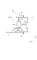
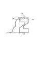
- FIG. 3 is a partial cross-sectional view taken along line III-III shown in FIGS. 1 and 2.
- FIG. 4 is a partial cross-sectional view taken along line IV-IV shown in FIGS. 1 and 2.
- FIG. 6 is a partial cross-sectional view taken along the line VI-VI shown in FIG. 5.
- FIG. 8 is a partial cross-sectional view taken along line VIII-VIII shown in FIG.
- FIG. 10 is a sectional view taken along line XX shown in FIG. 9. It is the figure which showed the deformation
- FIG. 14 is a partial cross-sectional view taken along line XIV-XIV shown in FIG. 13.
- FIG. 1 It is a perspective view which shows the member used for the vehicle body side part structure which concerns on 3rd Embodiment, (a) is an outer panel, (b) is an inner panel, (c) is a backup panel. It is a partial cross section figure of the vehicle body side part structure which concerns on 4th Embodiment.
- the vertical direction means the vertical direction in the vehicle vertical direction
- the front-rear direction means the front-rear direction in the vehicle front-rear direction.
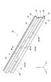
- FIG. 1 is a perspective view showing a part of the vehicle body side structure according to the first embodiment.
- FIG. 2 is a plan view showing a part of the vehicle body side part structure according to the first embodiment.
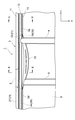
- FIG. 3 is a partial cross-sectional view taken along the line III-III shown in FIGS.
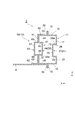
- FIG. 4 is a partial cross-sectional view taken along line IV-IV shown in FIGS.
- an arrow X indicates an inner side (vehicle interior side) direction in the vehicle width direction
- an arrow Y indicates a front side in the vehicle longitudinal direction
- an arrow Z indicates an upper direction in the vehicle vertical direction. Show.
- the vehicle body side structure 1 is joined to a center pillar 2 erected in the vehicle vertical direction at a vehicle longitudinal direction central portion and a lower end portion of the center pillar 2.
- a rocker 3 extending in the vehicle longitudinal direction, a front floor cross member 4 extending in the vehicle width direction and joined to the rocker 3, and a vehicle disposed in the vehicle longitudinal direction rear side of the front floor cross member 4
- a rear floor cross member 5 that extends in the width direction and is joined to the rocker 3.
- 1 and 2 show only the vehicle body side structure 1 on the left side of the vehicle, the center pillar 2 and the rocker 3 are also provided on the vehicle body side structure 1 on the right side of the vehicle.
- the center pillar 2 is joined to the outer side in the vehicle width direction (the vehicle outer side) of the rocker 3 at a position facing the rear floor cross member 5 with the rocker 3 interposed therebetween.
- the rocker 3 is disposed on the outer side of the rocker 3 in the vehicle width direction, on the inner panel 12 on the inner side of the outer panel 11 in the vehicle width direction (inside the vehicle compartment), and on the inner side of the inner panel 12 in the vehicle width direction.
- the backup panel 13 is provided.
- FIG. 5 is a perspective view showing a part of the outer panel.
- FIG. 6 is a partial cross-sectional view taken along line VI-VI shown in FIG.
- the outer panel 11 extends in the longitudinal direction of the vehicle and is joined to the center pillar 2 on the outer side in the vehicle width direction.
- the outer panel 11 and the center pillar 2 are joined by, for example, resistance welding such as spot welding.
- the outer panel 11 is formed by bending a single steel plate. That is, the outer panel 11 is disposed at the uppermost portion in the vehicle vertical direction and extends in the vehicle vertical direction, and the top side portion 16 extends from the vehicle vertical direction lower end edge of the upper flange portion 15 toward the vehicle width direction outer side.
- An upper side portion 17 extending from the outer edge in the vehicle width direction of the top portion 16 toward the lower side in the vehicle vertical direction, a lower flange portion 18 disposed at the lowermost portion in the vehicle vertical direction and extending in the vehicle vertical direction, and a lower flange portion 18 A bottom side 19 that extends from the vehicle vertical direction upper end edge toward the vehicle width direction outer side, a lower side side portion 20 that extends from the vehicle width direction outer side edge of the bottom side portion 19 toward the vehicle vertical direction upper side, and an upper side side portion 17
- An outer panel bead portion 21 that is recessed from the vehicle vertical direction upper end edge of the vehicle vertical direction lower end side portion 20 to the vehicle width direction inner side (inner panel 12 side).
- a ridge line extending in the vehicle front-rear direction is formed between the upper flange portion 15 and the top side portion 16.
- a ridge line extending in the vehicle front-rear direction is formed between the top side portion 16 and the upper side portion 17.
- a ridge line extending in the vehicle front-rear direction is formed between the lower flange portion 18 and the bottom side portion 19. Further, a ridge line extending in the vehicle front-rear direction is formed between the bottom side 19 and the lower side 20.
- the angle formed by the top side 16 and the upper side 17 is substantially a right angle. Further, the angle formed between the bottom side 19 and the lower side 20 is substantially a right angle. In addition, the top side 16 and the bottom side 19 are arranged substantially in parallel. Further, the upper side portion 17 and the lower side portion 20 are arranged in the same straight line. Actually, the upper side portion 17 and the lower side portion 20 are formed in a single flat plate shape, and the center portion in the vehicle vertical direction is recessed toward the inner side in the vehicle width direction so that the outer panel bead is formed. A portion 21 is formed.
- the outer panel bead portion 21 extends in the vehicle front-rear direction.
- the outer panel bead portion 21 is disposed at the vehicle front-rear direction central portion and extends in the vehicle front-rear direction
- the outer panel bead central portion 22 is disposed at both ends of the vehicle front-rear direction and extends in the vehicle front-rear direction.
- the outer panel bead central portion 22 and the pair of outer panel bead end portions 27 are formed in a single groove shape having no joints or steps.
- the outer panel bead central portion 22 of the outer panel bead portion 21 is a portion disposed approximately between the front floor cross member 4 and the rear floor cross member 5 (see FIG. 2).
- the outer panel bead central portion 22 has an outer panel bead upper side portion 23 that extends inward in the vehicle width direction from the vehicle vertical direction lower end edge of the upper side portion 17 and the vehicle of the lower side portion 20.
- the outer panel bead lower side portion 24 extending inward in the vehicle width direction from the upper edge in the vertical direction, the vehicle width direction inner side edge of the outer panel bead upper side portion 23, and the vehicle width direction inner side edge of the outer panel bead lower side portion 24.
- an outer panel bead base 25 extending in the vehicle vertical direction.
- a ridge line extending in the vehicle front-rear direction is formed between the upper side portion 17 and the outer panel bead upper side portion 23.
- a ridge line extending in the vehicle front-rear direction is formed between the upper side 23 of the outer panel bead and the bottom side 25 of the outer panel bead.
- a ridge line extending in the vehicle front-rear direction is formed between the outer panel bead bottom side 25 and the outer panel bead lower side 24.
- a ridge line extending in the vehicle front-rear direction is formed between the outer panel bead lower side 24 and the lower side 20.
- the upper surface 23a of the upper side 23 of the outer panel bead facing the upper side in the vehicle vertical direction is an inclined surface facing inward in the vehicle width direction.
- the inclination angle of the upper surface 23a toward the inner side in the vehicle width direction gradually changes so as to gradually decrease from the vehicle front-rear direction center to the pair of outer panel bead ends 27.
- the inclination angle of the upper surface 23 a toward the vehicle width direction inner side is 0 °
- the upper side bead upper edge 23 is the lower edge of the upper side 17 in the vehicle vertical direction. Extends only inward in the vehicle width direction.
- corner which the outer panel bead bottom side part 25 and the outer panel bead lower side part 24 comprise is a substantially right angle.
- corner which the outer panel bead lower part 24 and the lower side part 20 comprise is a substantially right angle.
- the depth recessed from the upper side portion 17 and the lower side portion 20 of the outer panel bead central portion 22 to the inside in the vehicle width direction is deepest in the vehicle front-rear direction central portion. That is, the center part of the outer panel bead center part 22 in the vehicle longitudinal direction is the deepest part of the depression. This depth gradually changes so as to gradually become shallower as it approaches the pair of outer panel bead ends 27. As shown in FIG. 5, the depth of the recess may be the same by a predetermined length in the vehicle longitudinal direction central portion of the outer panel bead central portion 22.
- the outer panel bead end portion 27 of the outer panel bead portion 21 includes an outer panel bead upper side portion 28 that extends inward in the vehicle width direction from the vehicle vertical direction lower end edge of the upper side portion 17, and a lower side portion.
- an outer panel bead lower side portion 29 extending inwardly in the vehicle width direction from an upper end edge in the vehicle vertical direction, an inner edge in the vehicle width direction of the upper side portion 28 of the outer panel bead, and an inner edge in the vehicle width direction of the lower side portion 29 of the outer panel bead.
- an outer panel bead base 30 extending in the vertical direction of the vehicle.
- a ridge line extending in the vehicle front-rear direction is formed between the upper side portion 17 and the outer panel bead upper side portion 28.
- a ridge line extending in the vehicle front-rear direction is formed between the upper side 28 of the outer panel bead and the bottom side 30 of the outer panel bead.
- a ridge line extending in the vehicle front-rear direction is formed between the outer panel bead bottom side portion 30 and the outer panel bead lower side portion 29.
- a ridge line extending in the vehicle front-rear direction is formed between the outer panel bead lower side portion 29 and the lower side portion 20.
- the angle formed by the upper side portion 17 and the outer panel bead upper side portion 28 is substantially a right angle. Further, the angle formed by the upper side 28 of the outer panel bead and the bottom side 30 of the outer panel bead is substantially a right angle. Further, the angle formed by the outer panel bead bottom side 30 and the outer panel bead lower side 29 is substantially a right angle.
- FIG. 7 is a perspective view showing a part of the inner panel.
- FIG. 8 is a partial cross-sectional view taken along line VIII-VIII shown in FIG.
- the inner panel 12 extends in the vehicle front-rear direction and is joined to the outer panel 11 on the outer side in the vehicle width direction.
- the outer panel 11 and the inner panel 12 are joined by, for example, resistance welding such as spot welding.
- the inner panel 12 is formed by bending a single steel plate. That is, the inner panel 12 is arranged at the uppermost part in the vehicle vertical direction and extends in the vehicle vertical direction, and the top side part 33 extends inward in the vehicle width direction from the vehicle vertical direction lower end edge of the upper flange part 32.
- the upper side portion 34 extending from the vehicle width direction inner side edge of the top side portion 33 toward the vehicle vertical direction lower side, the lower flange portion 35 disposed at the lowermost portion of the vehicle vertical direction and extending in the vehicle vertical direction, and the lower flange portion 35
- a bottom side portion 36 extending inward in the vehicle width direction from an upper end edge in the vehicle vertical direction
- a lower side portion 37 extending inward in the vehicle vertical direction from an inner edge in the vehicle width direction of the bottom portion 36
- An inner panel bead portion 38 that is recessed from the vehicle vertical direction lower end edge of 34 and the vehicle vertical direction upper end edge of the lower side portion 37 toward the vehicle width direction outer side (outer panel 11 side).
- a ridge line extending in the vehicle front-rear direction is formed between the upper flange portion 32 and the top side portion 33. Further, a ridge line extending in the vehicle front-rear direction is formed between the top side 33 and the upper side 34. A ridge line extending in the vehicle front-rear direction is formed between the lower flange portion 35 and the bottom side portion 36. A ridge line extending in the vehicle front-rear direction is formed between the bottom side portion 36 and the lower side portion 37.
- the angle formed by the top side 33 and the upper side 34 is substantially a right angle. Further, the angle formed by the bottom side part 36 and the lower side part 37 is substantially a right angle.
- the top side 33 and the bottom side 36 are arranged substantially in parallel.
- the upper side portion 34 and the lower side portion 37 are arranged in the same straight line.
- the upper side portion 34 and the lower side portion 37 are formed in a single flat plate shape, and the inner panel is formed by the depression of the vehicle vertical direction central portion toward the vehicle width direction outer side. A bead portion 38 is formed.
- the inner panel bead portion 38 extends in the vehicle front-rear direction. And the inner panel bead part 38 is arrange
- a pair of inner panel bead ends 44 extending in the front-rear direction.
- the inner panel bead central portion 39 and the pair of inner panel bead end portions 44 are formed in a single groove shape having no joints or steps.
- the inner panel bead central portion 39 of the inner panel bead portion 38 is a portion disposed approximately between the front floor cross member 4 and the rear floor cross member 5 as in the outer panel bead central portion 22 (see FIG. 2). ).
- the inner panel bead center portion 39 is formed from an inner panel bead upper side portion 40 that extends from the vehicle vertical direction lower end edge of the upper side portion 34 toward the vehicle width direction outer side, and from the vehicle vertical direction upper end edge of the lower side portion 37 to the vehicle vertical direction.
- An inner panel bead lower side 41 extending outward in the vehicle width direction while inclining upward in the direction, an outer edge in the vehicle width direction of the inner panel bead upper side 40, and an outer edge in the vehicle width direction of the inner panel bead lower side 41
- an inner panel bead bottom side 42 extending in the vehicle vertical direction.
- a ridge line extending in the vehicle front-rear direction is formed between the upper side portion 34 and the inner panel bead upper side portion 40. Further, a ridge line extending in the vehicle front-rear direction is formed between the upper side 40 of the inner panel bead and the bottom side 42 of the inner panel bead. Further, a ridge line extending in the vehicle front-rear direction is formed between the inner panel bead bottom side portion 42 and the inner panel bead lower side portion 41. Further, a ridge line extending in the vehicle front-rear direction is formed between the inner panel bead lower side portion 41 and the lower side portion 37.
- the lower surface 41a of the inner panel bead lower side 41 facing the lower side in the vehicle vertical direction is an inclined surface facing outward in the vehicle width direction.
- the inclination angle of the lower surface 41a to the outer side in the vehicle width direction gradually changes so as to gradually decrease as it approaches the pair of inner panel bead end portions 44 from the center portion in the vehicle longitudinal direction.
- the inclination angle of the lower surface 41a to the outside in the vehicle width direction is 0 °
- the inner panel bead lower side 41 is in the vehicle vertical direction of the upper side 34. It extends only from the lower edge to the outside in the vehicle width direction.
- the inclination angle of the lower surface 41a of the inner panel bead lower side part 41 is substantially the same as the inclination angle of the upper surface 23a of the outer panel bead upper side part 23.
- the angle formed by the upper side portion 34 and the inner panel bead upper side portion 40 is substantially a right angle.
- corner which the inner panel bead upper side part 40 and the inner panel bead bottom side part 42 comprise is a substantially right angle.
- the depth recessed from the upper side portion 34 and the lower side portion 37 of the inner panel bead center portion 39 outward in the vehicle width direction is deepest in the vehicle front-rear direction center portion. That is, the center part of the inner panel bead center part 39 in the vehicle front-rear direction is the deepest part of the depression.
- the depth gradually changes so as to gradually become shallower as it approaches the pair of inner panel bead ends 44.
- the outer panel bead central portion 22 of the outer panel 11 and the inner panel bead central portion 39 of the inner panel 12 are drawn when the outer panel 11 is pulled upward in the vehicle vertical direction and inward in the vehicle width direction.
- the outer panel bead central portion 22 is disposed at a position where it abuts on the inner panel bead central portion 39.
- the lower surface 41a of the inner panel bead lower side part 41 is arrange
- the lower surface 41a of the inner panel bead lower side portion 41 is disposed on the inner side in the vehicle width direction of the upper surface 23a of the outer panel bead upper side portion 23, and the upper surface 23a of the outer panel bead upper side portion 23 and the inner panel bead in a vehicle side view.
- the lower surface 41 a of the lower side portion 41 overlaps.
- the inner panel bead end portion 44 of the inner panel bead portion 38 includes an inner panel bead upper side portion 45 extending from the vehicle vertical direction lower end edge of the upper side portion 34 toward the vehicle width direction outer side, and a lower portion.
- Inner panel bead lower side portion 46 extending from the vehicle upper and lower upper end edge of side side portion 37 toward the vehicle width direction outer side, vehicle width direction outer side edge of inner panel bead upper side portion 45 and vehicle width of inner panel bead lower side portion 46.
- An inner panel bead base 47 that is connected to the outer edge of the direction and extends in the vehicle vertical direction.
- a ridge line extending in the vehicle front-rear direction is formed between the upper side portion 34 and the inner panel bead upper side portion 45. Further, a ridge line extending in the vehicle front-rear direction is formed between the inner panel bead upper side 45 and the inner panel bead bottom side 47. Further, a ridge line extending in the vehicle front-rear direction is formed between the inner panel bead bottom side 47 and the inner panel bead lower side 46. A ridge line extending in the vehicle front-rear direction is formed between the inner panel bead lower side portion 46 and the lower side portion 37.
- the angle formed by the upper side portion 34 and the inner panel bead upper side portion 45 is substantially a right angle.
- corner which the inner panel bead upper side part 45 and the inner panel bead bottom side part 47 comprise is a substantially right angle.
- the angle formed by the inner panel bead bottom side 47 and the inner panel bead lower side 46 is substantially a right angle.
- the angle formed by the inner panel bead lower side portion 46 and the lower side portion 37 is substantially a right angle.
- the inner panel 12 configured in this manner has the upper flange portion 32 joined to the upper flange portion 15 of the outer panel 11 and the lower flange portion 35 connected to the lower flange portion 18 of the outer panel 11. It is joined. Thereby, the outer panel 11 and the inner panel 12 form a closed cross section.
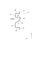
- FIG. 9 is a perspective view showing a part of the backup panel.
- 10 is a cross-sectional view taken along line XX shown in FIG.
- the backup panel 13 extends in the vehicle front-rear direction from the front end in the vehicle front-rear direction of the outer panel 11 and the inner panel 12 to the rear end in the vehicle front-rear direction.
- the backup panel 13 is joined to the inner panel 12 on the outer side in the vehicle width direction, and is joined to the floor panel 6 on the inner side in the vehicle width direction.
- the joining of the inner panel 12 and the backup panel 13 and the joining of the backup panel 13 and the floor panel are performed by, for example, resistance welding such as spot welding.
- the backup panel 13 is formed by bending a single steel plate.
- the backup panel 13 includes a backup panel center bulging portion 50 disposed in the vehicle longitudinal direction central portion, and a pair of backup panel end portions 59 disposed at both ends of the backup panel central bulging portion 50 in the vehicle longitudinal direction. It is equipped with.
- the backup panel central bulging portion 50 is a portion disposed approximately between the front floor cross member 4 and the rear floor cross member 5 and is located at a position facing the center pillar 2 with the outer panel 11 and the inner panel 12 interposed therebetween. Has been placed.
- the backup panel center bulging portion 50 only needs to be disposed at least between the front floor cross member 4 and the rear floor cross member 5, and extends to the front side in the vehicle front-rear direction from the front floor cross member 4.
- the rear floor cross member 5 may extend to the rear side in the vehicle front-rear direction.
- the backup panel center bulging portion 50 of the backup panel 13 is arranged at the uppermost portion in the vehicle vertical direction and extends in the vehicle width direction, and from the vehicle width direction inner edge of the upper flange portion 51 to the vehicle vertical direction lower side A side portion 52 extending toward the vehicle width, a widened portion 53 extending from the vehicle vertical direction lower end edge of the side portion 52 toward the vehicle width direction inner side, and a vehicle width direction inner end edge of the wide portion 53 to the vehicle width direction inner side.
- An upper inclined side portion 54 that extends toward the lower side in the vehicle vertical direction while inclining, a lower flange portion 55 that is disposed at the lowermost portion in the vehicle vertical direction and extends in the vehicle width direction, and a vehicle from an outer edge in the vehicle width direction of the lower flange portion 55.
- a lower inclined side portion 56 that extends upward in the vehicle vertical direction while inclining outward in the width direction, a vehicle vertical direction lower end edge of the upper inclined side portion 54, and a vehicle upper direction in the lower inclined side portion 56. It has been connected to the edge and the backup panel bead center portion 57 recessed toward the outside in the vehicle width direction, a.
- a ridge line extending in the vehicle front-rear direction is formed between the upper flange portion 51 and the side portion 52.
- a ridge line extending in the vehicle front-rear direction is formed between the side portion 52 and the widened portion 53.
- a ridge line that extends in the vehicle front-rear direction while being curved is formed between the widened portion 53 and the upper inclined side portion 54.
- a ridge line extending in the vehicle front-rear direction while being curved is formed between the upper inclined side portion 54 and the backup panel bead center portion 57.
- a ridge line that extends in the vehicle front-rear direction while being curved is formed between the backup panel bead center portion 57 and the lower inclined side portion 56.
- a ridge line extending in the vehicle front-rear direction while being curved is formed between the lower inclined side portion 56 and the lower flange portion 55.
- the angle formed by the upper flange portion 51 and the side portion 52 is substantially a right angle. Further, the angle formed by the side portion 52 and the widened portion 53 is substantially a right angle. Further, the upper inclined side portion 54 and the lower inclined side portion 56 are arranged on the same straight line. Actually, the upper inclined side portion 54 and the lower inclined side portion 56 are formed as a single flat plate, and the center portion of the vehicle in the vertical direction is recessed outward in the vehicle width direction so that the backup panel is formed. A bead central portion 57 is formed.
- the width that bulges inward in the vehicle width direction from the side portion 52 of the widened portion 53 is widest at the center in the vehicle longitudinal direction. That is, the center part in the vehicle front-rear direction of the widened portion 53 bulges most inside in the vehicle width direction.
- the width gradually changes so as to gradually narrow as the pair of backup panel end portions 59 approaches.
- the inclination angle of the upper inclined side portion 54 and the lower inclined side portion 56 in the vehicle width direction is gradually changed so as to gradually decrease from the center portion in the vehicle longitudinal direction toward the pair of backup panel end portions 59.
- the inclination angle of the upper inclined side portion 54 and the lower inclined side portion 56 in the vehicle width direction is 0 °, and the upper inclined side portion 54 becomes the widened portion 53.
- the lower inclined side portion 56 extends only from the outer edge in the vehicle width direction of the lower flange portion 55 to the upper side in the vehicle vertical direction.
- the backup panel bead central portion 57 extends in the vehicle front-rear direction.
- the shape of the backup panel bead central portion 57 may be any shape. In the drawing, the backup panel bead central portion 57 is formed only on a part of the backup panel central bulge portion 50, but the backup panel bead central portion 57 is formed on the entire backup panel central bulge portion 50. Also good.
- the backup panel central bulging portion 50 configured as described above has an upper flange portion 51 joined to the top side portion 33 of the inner panel 12 and a side portion 52 which is the upper side portion of the inner panel 12.
- the lower flange portion 55 is joined to the floor panel 6.
- a closed cross section is formed by the inner panel 12, the backup panel central bulging portion 50, and the floor panel 6.
- the backup panel center bulging portion 50 is joined to the inner panel 12 in this way, so that the upper flange portion 51 and the side portion 52 provide a space between the top side portion 33 and the upper side portion 34 of the inner panel 12.
- the ridgeline is reinforced.
- the backup panel end portion 59 of the backup panel 13 is arranged at the top in the vehicle vertical direction and extends in the vehicle width direction, and from the vehicle width direction inner edge of the upper flange portion 60 toward the vehicle vertical direction lower side.
- An upper side 61 that extends in the vehicle vertical direction
- a lower flange 62 that extends in the vehicle width direction
- a lower side that extends from the outer edge in the vehicle width direction of the lower flange 62 toward the upper side in the vehicle vertical direction.
- a backup panel bead end portion 64 that is connected to a vehicle vertical direction lower end edge of the upper side portion 61 and a vehicle vertical direction upper end edge of the lower side portion 63 and protrudes inward in the vehicle width direction. I have.
- a ridge line extending in the vehicle front-rear direction is formed between the upper flange portion 60 and the upper side portion 61. Further, a ridge line extending in the vehicle front-rear direction is formed between the lower flange portion 62 and the lower side portion 63.
- the angle formed by the upper flange portion 60 and the upper side portion 61 is substantially a right angle. Further, the angle formed by the lower flange portion 62 and the lower side portion 63 is substantially a right angle. Further, the upper side portion 61 and the lower side portion 63 are arranged in the same straight line.
- the upper inclined side portion 54 and the lower inclined side portion 56 are formed as a single flat plate, and the center portion of the vehicle in the vertical direction is recessed outward in the vehicle width direction so that the backup panel is formed. A bead central portion 57 is formed.
- the upper flange portion 60 of the backup panel end portion 59 is connected to the upper flange portion 51 of the backup panel central bulge portion 50, and the upper side portion 61 of the backup panel end portion 59 is bulged in the backup panel central bulge portion 50.
- the lower side flange portion 62 of the backup panel center bulge portion 50 is connected to the lower flange portion 55 of the backup panel end portion 59. ing.
- the backup panel bead end portion 64 extends in the vehicle front-rear direction.
- the backup panel bead end portion 64 is formed on the entire backup panel end portion 59, but the backup panel bead end portion 64 may be formed only on a part of the backup panel end portion 59.
- the backup panel bead end portion 64 includes a backup panel bead upper side portion 65 extending inward in the vehicle width direction from the vehicle vertical direction lower end edge of the upper side portion 61, and a vehicle width from the vehicle vertical direction upper end edge of the lower side portion 63.
- the vehicle is connected in the vehicle width direction inner edge of the backup panel bead lower side portion 66 extending inward in the direction of the vehicle, the vehicle width direction inner side edge of the backup panel bead upper side portion 65, and the vehicle panel in the vehicle vertical direction.
- An extended backup panel bead top side 67 is an extended backup panel bead top side 67.
- a ridge line extending in the vehicle front-rear direction is formed between the upper side portion 61 and the backup panel bead upper side portion 65. Further, a ridge line extending in the vehicle front-rear direction is formed between the backup panel bead upper side portion 65 and the backup panel bead top side portion 67. A ridge line extending in the vehicle front-rear direction is formed between the backup panel bead top side 67 and the backup panel bead lower side 66. A ridge line extending in the vehicle front-rear direction is formed between the backup panel bead lower side portion 66 and the lower side portion 63.
- the angle formed by the upper side 61 and the upper side 65 of the backup panel bead is substantially a right angle. Further, the angle formed by the upper side 65 of the backup panel bead and the top side 67 of the backup panel bead is substantially a right angle. Further, the angle formed between the backup panel bead top side 67 and the backup panel bead lower side 66 is substantially a right angle. Further, the angle formed between the lower side portion 66 of the backup panel bead and the lower side portion 63 is substantially a right angle.
- the backup panel end portion 59 configured in this way has an upper flange portion 60 joined to the top side portion 33 of the inner panel 12, and an upper side portion 61 as an upper side portion of the inner panel 12. 34, the lower side part 63 is joined to the lower side part 37 of the inner panel 12, and the lower flange part 62 is joined to the floor panel 6.
- a closed cross section is formed by the backup panel bead end portion 64 of the backup panel end portion 59 and the inner panel bead end portion 44 of the inner panel 12.
- the upper flange portion 60 and the upper side portion 61 provide a space between the top side portion 33 and the upper side portion 34 of the inner panel 12.
- the ridgeline is reinforced.
- the front floor cross member 4 and the rear floor cross member 5 are joined to the central bulging portion 50 of the backup panel. More specifically, the front floor cross member 4 is joined to the front side portion of the backup panel center bulging portion 50 in the vehicle front-rear direction, and the rear floor cross member 5 is front and rear of the backup panel center bulging portion 50 in the vehicle. It is joined to the direction rear side part. Joining of the backup panel center bulging portion 50 to the front floor cross member 4 and the rear floor cross member 5 is performed by, for example, resistance welding such as spot welding.
- the front floor cross member 4 is formed at substantially the same height as the central bulging portion 50 of the backup panel.
- the rear floor cross member 5 is disposed at the foot of a rear occupant who gets on the rear seat, the rear floor cross member 5 is formed at a height lower than the central bulging portion 50 of the backup panel.
- the rear floor cross member 5 is formed at a height that is half or less of the backup panel center bulge 50.
- the front floor cross member 4 and the rear floor cross member 5 extend in the vehicle width direction from the backup panel center bulge 50 on the right side of the vehicle to the backup panel center bulge 50 on the left side of the vehicle.
- the rocker 3 increases the rigidity in the vehicle width direction and the vehicle front-rear direction. Collision performance corresponding to various collision modes can be improved.
- the outer panel bead central portion 22 is formed on the outer panel 11 and the inner panel bead central portion 39 is formed on the inner panel 12. The rigidity of the is increased.
- the vehicle body side structure 1 includes an outer panel bead central portion 22 and an inner panel bead central portion 39 that are arranged such that when the outer panel 11 is pulled upward in the vehicle vertical direction and inward in the vehicle width direction, the outer panel bead central portion 22 is the inner panel. It is arranged at a position where it abuts against the bead central portion 39. Thereby, at the time of a side collision, the inner panel bead central portion 39 inhibits the movement of the outer panel bead central portion 22 in the vehicle vertical direction upper side and the vehicle width direction inner side, so that the deformation of the outer panel 11 is suppressed.
- the inner panel bead central portion 39 is disposed above the outer panel bead central portion 22 in the vehicle vertical direction, the inner panel bead central portion is pulled when the outer panel 11 is pulled upward in the vehicle vertical direction.
- the outer panel bead central portion 22 can be reliably brought into contact with 39.
- the upper surface 23a of the outer panel bead central portion 22 is an inclined surface facing inward in the vehicle width direction, and the lower surface 41a of the inner panel bead central portion 39 is inclined toward the outer side in the vehicle width direction.
- the upper surface 23a and the lower surface 41a can face each other. Thereby, since the upper surface 23a and the lower surface 41a can be brought into surface contact at the time of a side collision, the outer panel bead central portion 22 is effectively inhibited from moving in the vehicle vertical direction upper side and the vehicle width direction inner side, The rotational displacement of the rocker 3 can be further suppressed.
- the inner panel bead central portion 39 is pulled when the outer panel 11 is pulled inward in the vehicle width direction.
- the outer panel bead central portion 22 can be reliably brought into contact with 39.
- the vehicle body side structure 1 has a vehicle body side structure because the outer panel bead central portion 22 and the inner panel bead central portion 39 extend in the vehicle front-rear direction and the deepest portion is formed in the vehicle front-rear direction central portion.
- the rigidity in the vehicle width direction at the center portion in the vehicle front-rear direction can be enhanced while achieving simplification and weight reduction.
- the outer panel bead end portion 27 extending in the vehicle front-rear direction is formed on the outer panel 11
- the inner panel bead end portion 44 extending in the vehicle front-rear direction is formed on the inner panel 12. The rigidity in the vehicle front-rear direction at the vehicle front-rear direction end is increased.
- the vehicle body side structure 1 includes a backup panel center bulging portion 50 at the center of the backup panel 13 in the vehicle front-rear direction, and a front floor cloth in the vicinity of both ends of the backup panel central bulging portion 50 in the vehicle front-rear direction. Since the member 4 and the rear floor cross member 5 are joined, the rigidity in the vehicle width direction at the center portion in the vehicle front-rear direction is increased. Moreover, at the time of a side collision, the backup panel center bulging portion 50 supports the rocker 3 from the inside in the vehicle width direction, so that the rocker 3 is prevented from falling inward in the vehicle width direction. As a result, the cross-sectional deformation of the rocker 3 is suppressed, and the rigidity of the vehicle body against a side collision is increased.
- the rocker 3 is further prevented from falling inward in the vehicle width direction.
- the vehicle body side structure 1 since the first closed cross section is formed by the inner panel 12, the backup panel central bulging portion 50, and the floor panel 6, the vehicle longitudinal direction and the vehicle width at the vehicle longitudinal direction central portion. Directional rigidity is increased.
- a second closed cross section is formed by an inner panel bead end portion 44 formed on the inner panel 12 and a backup panel bead end portion 64 formed on the backup panel 13. .
- the rigidity in the vehicle front-rear direction and the vehicle width direction at the end portion in the vehicle front-rear direction is enhanced by the second closed cross section.
- the number of ridge lines extending in the vehicle front-rear direction is increased. ing. For this reason, when there is a load input in the vehicle longitudinal direction, the input load can be shared by the increased ridgeline. Thereby, collision performance can be improved.
- the ridge line between the top side 33 and the upper side 34 of the inner panel 12 is reinforced by the upper flange 51 and the side 52 of the backup panel center bulge 50. ing. For this reason, the shape maintenance rigidity of this ridgeline is improved, and it can suppress that the inner panel 12 deform
- the side part 52 is joined to the upper side part 34 of the inner panel 12, and the angle formed by the side part 52 and the widened part 53 is substantially a right angle, so that the side part 52 and the widened part are widened.
- the angle formed by the side part 52 and the widened part 53 is substantially a right angle, so that the side part 52 and the widened part are widened.
- FIG. 11 is a diagram showing a deformation mode at the time of a side collision in the conventional vehicle body side part structure.
- FIG. 12 is a view showing a deformation mode at the time of a side collision in the vehicle body side part structure according to the first embodiment.
- the rocker 101 used in the conventional vehicle body side structure 100 includes an outer panel 102 disposed on the outer side in the vehicle width direction and an inner panel 103 disposed on the inner side in the vehicle width direction. Yes.
- the outer panel 102 and the inner panel 103 are joined together to form a rectangular closed cross section.
- a rear floor cross member 5 is disposed on the inner side in the vehicle width direction of the center pillar 2 with the rocker 101 interposed therebetween. For this reason, the rear floor cross member 5 tries to support the rocker 101 from which the rocker 101 is about to fall inward in the vehicle width direction.
- the rear floor cross member 5 is lower than the backup panel center bulge 50. Therefore, the rear floor cross member 5 cannot support the rocker 101 where the rocker 101 tries to fall inward in the vehicle width direction, and the rocker 101 falls down inward in the vehicle width direction so as to rotate.
- the rocker 3 includes a backup panel central bulging portion 50 of the backup panel 13 and an upper inclined side of the backup panel central bulging portion 50.
- the inner panel bead central portion 39 of the inner panel bead portion 38 enhances the rigidity in the vehicle width direction. For this reason, compared with the conventional vehicle body side part structure 100, while the deformation amount of the rocker 3 becomes small, the fall amount to the inner side of the center pillar 2 in the vehicle width direction becomes small.
- the outer panel bead central portion 22 contacts the inner panel bead central portion 39, so that the rocker 3 is deformed to fall inward in the vehicle width direction. Be blocked. For this reason, as compared with the conventional vehicle body side structure 100, the amount of deformation of the rocker 3 is further reduced, and the amount of the center pillar 2 falling inward in the vehicle width direction is further reduced.
- FIG. 13 is a perspective view showing a part of the vehicle body side part structure according to the second embodiment.
- 14 is a partial cross-sectional view taken along line XIV-XIV shown in FIG.
- the vehicle body side part structure 71 according to the second embodiment is basically the same as the vehicle body side part structure 1 according to the first embodiment, and the vehicle back-and-forth direction of the backup panel is shown. Only the end structure is different. For this reason, in the following description, only the part different from the first embodiment will be described, and the description of the same part as the first embodiment will be omitted.
- the backup panel 72 of the rocker 3 constituting the vehicle body side part structure 71 according to the second embodiment is basically the same as the backup panel 13 of the rocker 3 constituting the vehicle body side part structure 1 according to the first embodiment. Only the point that the backup panel end portion 59 is changed to the backup panel end portion 74 is different from the vehicle body side portion structure 1 according to the first embodiment.
- the backup panel end portion 74 is disposed at the uppermost vehicle vertical direction and extends in the vehicle width direction, and the upper side extends from the vehicle width direction inner edge of the upper flange portion 75 downward in the vehicle vertical direction.
- the lower bead top side 79 extending from the upper end in the vehicle vertical direction of the lower bead side portion 78 toward the vehicle width direction outer side and the vehicle width direction outer end edge of the lower bead top side 79 extending upward in the vehicle vertical direction.
- a bag that is connected to the vehicle vertical direction lower end edge of the lower side part 80 and the upper side part 76 and the vehicle vertical direction upper end edge of the lower side part 80 and protrudes inward in the vehicle width direction.
- a ridge line extending in the vehicle front-rear direction is formed between the lower flange portion 77 and the lower bead side portion 78. Further, a ridge line extending in the vehicle front-rear direction is formed between the lower bead side portion 78 and the lower bead top portion 79. In addition, a ridge line extending in the vehicle front-rear direction is formed between the lower bead top portion 79 and the lower side portion 80.
- the angle formed by the upper flange portion 75 and the upper side portion 76 is substantially a right angle.
- the angle formed by the lower flange portion 77 and the lower bead side portion 78 is substantially a right angle.
- the angle formed by the lower bead side portion 78 and the lower bead top portion 79 is substantially a right angle.
- the angle formed by the lower bead top side 79 and the lower side 80 is substantially a right angle.
- the lower bead side portion 78 and the lower bead top portion 79 are bead-shaped convex portions that protrude from the lower flange portion 77 and the lower side portion 80 upward in the vehicle vertical direction and inward in the vehicle width direction.
- the lower bead side portion 78 and the lower bead top portion 79 extend in the vehicle front-rear direction.
- the lower bead side portion 78 and the lower bead top portion 79 are formed substantially on the entire backup panel end portion 74, but the lower bead side portion 78 and the lower bead portion are formed on the entire backup panel end portion 74.
- the top side 79 may be formed, and the lower bead side side 78 and the lower bead top side 79 may be formed only at the vehicle longitudinal direction end of the backup panel end 74.
- the backup panel end 74 configured as described above has an upper flange portion 75 joined to the top side portion 33 of the inner panel 12, and an upper side portion 76 joined to the upper side portion 34 of the inner panel 12.
- the side part 80 is joined to the lower side part 37 of the inner panel 12, and the lower flange part 77 is joined to the floor panel 6.
- a closed cross section is formed by the backup panel bead end portion 82 of the backup panel end portion 74 and the inner panel bead end portion 44 of the inner panel 12, and the lower bead side portion 78 and the lower portion of the backup panel end portion 74 are formed.
- a closed cross section is formed by the bead top side 79, the lower side 37 of the inner panel 12, and the floor panel 6. Further, by joining the backup panel end 74 to the inner panel 12 in this way, the upper flange portion 75 and the upper side portion 76 provide a space between the top side portion 33 and the upper side portion 34 of the inner panel 12.
- the ridgeline is reinforced.
- the rigidity in the vehicle front-rear direction and the vehicle width direction at the end portion in the vehicle front-rear direction is increased.
- a plurality of ridge lines extending in the vehicle front-rear direction are formed in the lower bead side portion 78 and the lower bead top portion 79 of the backup panel end 74 forming the second closed section, thereby extending in the vehicle front-rear direction.
- the number of ridges has been increased. For this reason, when there is a load input in the vehicle longitudinal direction, the input load can be shared by the increased ridgeline. Thereby, collision performance can be improved.
- this closed cross section increases the rigidity of the joint portion between the inner panel 12 and the floor panel 6, and the bending of the inner panel 12 with respect to the floor panel 6 can be suppressed, so that the rocker 3 falls inward in the vehicle width direction. Can be further suppressed.
- FIG. 15 is a perspective view showing members used in the vehicle body side part structure according to the third embodiment, wherein (a) is an outer panel, (b) is an inner panel, and (c) is a backup panel.
- the outer panel 11a, the inner panel 12a, and the backup panel 13a used in the vehicle body side structure according to the third embodiment have the strength changed in the vehicle vertical direction.
- the strength of the upper part A of the outer panel 11a, the inner panel 12a and the backup panel 13a in the upper and lower direction of the vehicle by heat treatment or the like is increased by the upper and lower parts of the inner panel 12a and the backup panel 13a. It is higher than the strength of the lower part B in the lower direction.
- the weight of the entire rocker can be reduced while ensuring the strength of the upper portion in the vehicle vertical direction.
- FIG. 16 is a partial cross-sectional view of the vehicle body side structure according to the fourth embodiment.
- the thickness of the outer panel 11b, the inner panel 12b, and the backup panel 13b used in the vehicle body side structure according to the fourth embodiment is changed in the vehicle vertical direction.
- the thickness of the outer panel 11b, the inner panel 12b, and the backup panel 13b is gradually increased from the lower edge in the vehicle vertical direction toward the upper edge in the vehicle vertical direction.
- left and right high-rigidity parts and the front and rear high-rigidity parts have been described, but the present invention does not need to include all of these, and it is sufficient that at least one is included.
- the left and right high-rigidity parts and the front and rear high-rigidity parts of the present invention are not limited to those described in the above embodiment, and any aspect can be used as long as the rigidity in the vehicle width direction and the vehicle front-rear direction can be increased. There may be.
- left and right high-rigidity portions and the front and rear high-rigidity portions of the present invention need not be formed on all of the outer panel, inner panel, and backup panel, and may be formed on at least one of the outer panel, inner panel, and backup panel.
- the backup panel 13 extends from the front end in the vehicle front-rear direction of the outer panel 11 and the inner panel 12 to the rear end in the vehicle front-rear direction, but at least from the front end in the vehicle front-rear direction of the outer panel 11 and the inner panel 12. It suffices if the outer panel 11 and the inner panel 12 are extended to a position closer to the rear end portion side in the vehicle front-rear direction than 2.
- the second closed section and the third closed section are described as being formed at both ends in the vehicle front-rear direction, but may be formed only at one end in the vehicle front-rear direction.
- the inner panel bead end portion 44 is formed only at one end portion of the inner panel 12 in the vehicle front-rear direction
- the backup panel bead end portion 64 is formed only at one end portion of the backup panel 13 in the vehicle front-rear direction.
- the second closed cross section can be formed only at one end in the vehicle front-rear direction.
- a third closed cross section is formed on the vehicle. It can be formed only at one end in the front-rear direction.
- the present invention can be used for a vehicle side structure in which a rocker is joined to a center pillar and a floor panel.
- SYMBOLS 1 Car body side part structure which concerns on 1st Embodiment, 2 ... Center pillar, 3 ... Rocker, 4 ... Front side floor cross member, 5 ... Rear side floor cross member, 6 ... Floor panel, 11 ... Outer panel, 11a ... Outer panel 11b ... Outer panel, 12 ... Inner panel, 12a ... Inner panel, 12b ... Inner panel, 13 ... Backup panel (reinforcing member), 13a ... Backup panel, 13b ... Backup panel, 15 ... Upper flange part, 16 ... Top side part, DESCRIPTION OF SYMBOLS 17 ... Upper side part, 18 ... Lower flange part, 19 ... Bottom side part, 20 ...
- Upper flange part, 52 ... Side edge part 53 ... Widening part, 54 ... Upper inclined side part, 55 ... Lower flange part, 56 ... Lower inclined side part, 57 ... Backup panel bead central part, 59 ... Backup panel end part, 60 ... Upper flange part, 61 ... Upper side Side, 62 ... Lower flange, 63 ... Lower side, 64 ... Backup panel bead end (first reinforcing member convex part), 65 ... Backup panel bead upper side, 66 ... Backup panel bead lower side, 67 ... Backup panel bead top side portion, 71 ... vehicle body side structure according to the second embodiment, 72 ... backup panel, 74 ... bar Edge of the cuckup panel, 75 ...
Landscapes
- Engineering & Computer Science (AREA)
- Chemical & Material Sciences (AREA)
- Combustion & Propulsion (AREA)
- Transportation (AREA)
- Mechanical Engineering (AREA)
- Body Structure For Vehicles (AREA)
Abstract
Description
図1は、第1の実施形態に係る車体側部構造の一部を示す斜視図である。図2は、第1の実施形態に係る車体側部構造の一部を示す平面図である。図3は、図1及び図2に示したIII-III線における一部断面図である。図4は、図1及び図2に示したIV-IV線における一部断面図である。なお、全図において、矢印Xは、車幅方向における内側(車室内側)方向を示しており、矢印Yは、車両前後方向における前方を示しており、矢印Zは、車両上下方向における上方を示している。
図13は、第2の実施形態に係る車体側部構造の一部を示す斜視図である。図14は、図13に示したXIV-XIV線における一部断面図である。
図15は、第3の実施形態に係る車体側部構造に用いる部材を示す斜視図であり、(a)はアウタパネル、(b)はインナパネル、(c)はバックアップパネルである。
図16は、第4の実施形態に係る車体側部構造の一部断面図である。
Claims (13)
- 車幅方向外側に配置されて車両前後方向に延設されるアウタパネルと車幅方向内側に配置されて車両前後方向に延設されるインナパネルとを備え、センタピラーに接合されるロッカと、
前記ロッカの車両上下方向下部に接合されるフロアパネルと、
少なくとも前記ロッカの前端部から前記センタピラーよりも前記ロッカの後端部側まで延設されて、前記インナパネル及び前記フロアパネルに接合される補強部材と、
有し、
前記ロッカ及び前記補強部材のうち少なくとも一方の車両前後方向中央部に、車幅方向の剛性が高められた左右高剛性部が形成され、
前記ロッカ及び前記補強部材のうち少なくとも一方の車両前後方向端部に、車両前後方向の剛性が高められた前後高剛性部が形成される、
車体側部構造。 - 前記アウタパネルの車両前後方向中央部に、前記インナパネル側へ向けて窪む第一のアウタパネル凹部が形成され、
前記インナパネルの車両前後方向中央部に、前記アウタパネル側へ向けて窪む第一のインナパネル凹部が形成される、
請求項1に記載の車体側部構造。 - 前記第一のアウタパネル凹部及び前記第一のインナパネル凹部は、前記アウタパネルが車両上下方向上側かつ車幅方向内側に引っ張られた際に、前記第一のアウタパネル凹部が前記第一のインナパネル凹部に当接する位置に配置されている、
請求項2に記載の車体側部構造。 - 前記第一のインナパネル凹部は、車両上下方向において前記第一のアウタパネル凹部の上方に配置される、
請求項3に記載の車体側部構造。 - 前記第一のアウタパネル凹部の車両上下方向上面が、車幅方向内側へ向いた傾斜面となっており、
前記第一のインナパネル凹部の車両上下方向下面が、車幅方向外側へ向いた傾斜面となっている、
請求項4に記載の車体側部構造。 - 前記第一のアウタパネル凹部及び前記第一のインナパネル凹部は、車両前後方向に延在し、車両前後方向中央部で最深部が形成されている、
請求項2~5の何れか一項に記載の車体側部構造。 - 前記補強部材は、車両前後方向中央部が車幅方向内側へ向けて膨出する膨出部となっており、
前記補強部材における前記膨出部の車両前後方向両端部付近に、それぞれ車幅方向に延設される一対のフロアクロスメンバが接合される、
請求項1~6の何れか一項に記載の車体側部構造。 - 前記膨出部は、前記インナパネルとの接合位置から前記フロアパネルとの接合位置へ向けて車幅方向内側に傾斜する、
請求項7に記載の車体側部構造。 - 前記インナパネルと前記補強部材と前記フロアパネルとで第一の閉断面が形成される、
請求項1~8の何れか一項に記載の車体側部構造。 - 前記インナパネルの車両前後方向両端部のうち少なくとも一方に、車幅方向外側へ向けて窪んで車両前後方向に延在する第二のインナパネル凹部が形成され、
前記補強部材の車両前後方向両端部のうち少なくとも一方に、車幅方向内側へ向けて突出して車両前後方向に延在する第一の補強部材凸部が形成され、
前記第二のインナパネル凹部と前記第一の補強部材凸部とで第二の閉断面が形成される、
請求項1~9の何れか一項に記載の車体側部構造。 - 前記補強部材の車両前後方向両端部のうち少なくとも一方の車両上下方向下側端部に、車幅方向内側へ向けて突出して車両前後方向に延在する第二の補強部材凸部が形成され、
前記前記第二の補強部材凸部と前記インナパネルと前記フロアパネルとで第三の閉断面が形成される、
請求項1~10の何れか一項に記載の車体側部構造。 - 前記インナパネルは、車両上下方向上側及び下側において前記アウタパネルと接合されるアッパーフランジ部及びロアフランジ部と、前記アッパーフランジ部から車幅方向内側へ延びる天辺部と、前記ロアフランジ部から車幅方向内側へ延びる底辺部と、前記天辺部及び前記底辺部の車幅方向内側端縁に接続される側辺部と、を備え、
前記補強部材は、前記天辺部及び前記側辺部に接合されて、前記天辺部と前記側辺部との間の稜線を補強する、
請求項1~11の何れか一項に記載の車体側部構造。 - 前記ロッカ及び前記補強部の強度が、車両上下方向下側よりも車両上下方向上側の方が高い、
請求項1~12の何れか一項に記載の車体側部構造。
Priority Applications (11)
| Application Number | Priority Date | Filing Date | Title |
|---|---|---|---|
| CN201180075007.4A CN103946102B (zh) | 2011-11-22 | 2011-11-22 | 车身侧部结构 |
| PCT/JP2011/076936 WO2013076818A1 (ja) | 2011-11-22 | 2011-11-22 | 車体側部構造 |
| KR1020147013463A KR101553187B1 (ko) | 2011-11-22 | 2011-11-22 | 차체 측부 구조 |
| AU2011381713A AU2011381713B2 (en) | 2011-11-22 | 2011-11-22 | Structure for side portion of vehicle body |
| JP2013545693A JP5673856B2 (ja) | 2011-11-22 | 2011-11-22 | 車体側部構造 |
| RU2014119970/11A RU2014119970A (ru) | 2011-11-22 | 2011-11-22 | Конструкция боковой части кузова транспортного средства |
| MX2014006132A MX2014006132A (es) | 2011-11-22 | 2011-11-22 | Estructura de parte lateral de cuerpo de vehiculo. |
| BR112014012133A BR112014012133A8 (pt) | 2011-11-22 | 2011-11-22 | estrutura de parte lateral de carroceria |
| US14/359,454 US9139234B2 (en) | 2011-11-22 | 2011-11-22 | Vehicle-body side part structure |
| EP11876324.2A EP2783948A1 (en) | 2011-11-22 | 2011-11-22 | Structure for side portion of vehicle body |
| PH12014501156A PH12014501156A1 (en) | 2011-11-22 | 2014-05-22 | Vehicle-body side part structure |
Applications Claiming Priority (1)
| Application Number | Priority Date | Filing Date | Title |
|---|---|---|---|
| PCT/JP2011/076936 WO2013076818A1 (ja) | 2011-11-22 | 2011-11-22 | 車体側部構造 |
Publications (1)
| Publication Number | Publication Date |
|---|---|
| WO2013076818A1 true WO2013076818A1 (ja) | 2013-05-30 |
Family
ID=48469297
Family Applications (1)
| Application Number | Title | Priority Date | Filing Date |
|---|---|---|---|
| PCT/JP2011/076936 Ceased WO2013076818A1 (ja) | 2011-11-22 | 2011-11-22 | 車体側部構造 |
Country Status (11)
| Country | Link |
|---|---|
| US (1) | US9139234B2 (ja) |
| EP (1) | EP2783948A1 (ja) |
| JP (1) | JP5673856B2 (ja) |
| KR (1) | KR101553187B1 (ja) |
| CN (1) | CN103946102B (ja) |
| AU (1) | AU2011381713B2 (ja) |
| BR (1) | BR112014012133A8 (ja) |
| MX (1) | MX2014006132A (ja) |
| PH (1) | PH12014501156A1 (ja) |
| RU (1) | RU2014119970A (ja) |
| WO (1) | WO2013076818A1 (ja) |
Cited By (4)
| Publication number | Priority date | Publication date | Assignee | Title |
|---|---|---|---|---|
| JP2013112180A (ja) * | 2011-11-29 | 2013-06-10 | Toyota Motor Corp | 車体側部構造 |
| WO2016146694A1 (en) | 2015-03-17 | 2016-09-22 | Autotech Engineering A.I.E. | Rockers for vehicles and vehicles comprising such rockers |
| JP2020040642A (ja) * | 2018-09-11 | 2020-03-19 | 現代自動車株式会社Hyundai Motor Company | 車両の車体フロア |
| JP7240648B1 (ja) | 2021-12-09 | 2023-03-16 | いすゞ自動車株式会社 | 車両のパネル構造 |
Families Citing this family (7)
| Publication number | Priority date | Publication date | Assignee | Title |
|---|---|---|---|---|
| FR3050167B1 (fr) * | 2016-04-14 | 2018-04-13 | Peugeot Citroen Automobiles Sa | Plancher avec des moyens anti sousmarinage |
| JP6958399B2 (ja) * | 2018-02-05 | 2021-11-02 | トヨタ自動車株式会社 | 車両骨格構造 |
| JP6713497B2 (ja) * | 2018-03-06 | 2020-06-24 | 株式会社豊田自動織機 | 車両用センタピラー |
| US11427261B2 (en) * | 2018-06-05 | 2022-08-30 | Nissan Motor Co., Ltd. | Vehicle body structure and method for manufacturing vehicle body |
| DE102018127368A1 (de) * | 2018-11-02 | 2020-05-07 | Benteler Automobiltechnik Gmbh | Schweller und Fahrzeugrahmen einer Fahrzeugkarosserie und Verfahren zur Herstellung eines Schwellers |
| US11084538B2 (en) * | 2019-05-24 | 2021-08-10 | GM Global Technology Operations LLC | Multi-flange extrusion member |
| JP7172887B2 (ja) * | 2019-07-02 | 2022-11-16 | トヨタ自動車株式会社 | 車体下部構造 |
Citations (9)
| Publication number | Priority date | Publication date | Assignee | Title |
|---|---|---|---|---|
| JPH0242875U (ja) * | 1988-09-20 | 1990-03-23 | ||
| JPH057585U (ja) * | 1991-07-15 | 1993-02-02 | 日産自動車株式会社 | 車体骨格部材構造 |
| JPH05262264A (ja) | 1992-03-19 | 1993-10-12 | Nissan Shatai Co Ltd | 車体の側部構造 |
| JPH09323669A (ja) * | 1996-04-04 | 1997-12-16 | Toyota Motor Corp | 車両の下部車体構造 |
| JP2004314845A (ja) * | 2003-04-17 | 2004-11-11 | Kikuchi Co Ltd | 車両のセンターピラー構造 |
| JP2007008398A (ja) * | 2005-07-04 | 2007-01-18 | Mazda Motor Corp | スライドドア車の下部車体構造 |
| JP2007314131A (ja) * | 2006-05-29 | 2007-12-06 | Toyota Motor Corp | 車体下部構造 |
| JP2009227104A (ja) * | 2008-03-24 | 2009-10-08 | Mazda Motor Corp | 自動車のフレーム構造 |
| JP2011136621A (ja) * | 2009-12-28 | 2011-07-14 | Honda Motor Co Ltd | 車体側部構造 |
Family Cites Families (14)
| Publication number | Priority date | Publication date | Assignee | Title |
|---|---|---|---|---|
| JPS5144023A (ja) | 1974-10-13 | 1976-04-15 | Masahisa Shimazaki | Zemukuritsupukyonyuki* |
| US4572571A (en) * | 1984-06-11 | 1986-02-25 | General Motors Corporation | Vehicle body floor pan assembly |
| JPH0547752Y2 (ja) * | 1987-08-04 | 1993-12-16 | ||
| JPH0242875A (ja) | 1988-05-24 | 1990-02-13 | Ricoh Co Ltd | カラー画像読取り装置 |
| JP2566466B2 (ja) | 1989-08-11 | 1996-12-25 | 日本スタッドウェルディング株式会社 | 締結部材の溶接方法 |
| JP2532325Y2 (ja) * | 1990-03-30 | 1997-04-16 | マツダ株式会社 | 車両の下部車体構造 |
| JP2707859B2 (ja) * | 1991-03-25 | 1998-02-04 | トヨタ自動車株式会社 | 車両のフロントボデー構造 |
| JPH057585A (ja) | 1991-07-04 | 1993-01-19 | Toshiba Corp | 頭部固定具 |
| US5388885A (en) * | 1993-02-01 | 1995-02-14 | General Motors Corporation | Body structure of a motor vehicle |
| US6126219A (en) * | 1998-08-31 | 2000-10-03 | Ford Global Technologies, Inc. | Underbody assembly for motor vehicles |
| JP4535850B2 (ja) * | 2004-11-18 | 2010-09-01 | ダイハツ工業株式会社 | 自動車の車体側部における補強構造 |
| DE602006008702D1 (de) | 2005-07-04 | 2009-10-08 | Mazda Motor | Unterbodenaufbau von einem Kraftfahrzeug mit Schiebetüren |
| JP4078657B1 (ja) * | 2006-11-24 | 2008-04-23 | いすゞ自動車株式会社 | 車両のボディサイド構造 |
| EP2527233B1 (en) * | 2007-04-04 | 2014-05-14 | Nippon Steel & Sumitomo Metal Corporation | Strength member for an automobile body |
-
2011
- 2011-11-22 EP EP11876324.2A patent/EP2783948A1/en not_active Withdrawn
- 2011-11-22 CN CN201180075007.4A patent/CN103946102B/zh not_active Expired - Fee Related
- 2011-11-22 RU RU2014119970/11A patent/RU2014119970A/ru not_active Application Discontinuation
- 2011-11-22 WO PCT/JP2011/076936 patent/WO2013076818A1/ja not_active Ceased
- 2011-11-22 AU AU2011381713A patent/AU2011381713B2/en not_active Ceased
- 2011-11-22 BR BR112014012133A patent/BR112014012133A8/pt not_active IP Right Cessation
- 2011-11-22 US US14/359,454 patent/US9139234B2/en not_active Expired - Fee Related
- 2011-11-22 JP JP2013545693A patent/JP5673856B2/ja not_active Expired - Fee Related
- 2011-11-22 KR KR1020147013463A patent/KR101553187B1/ko not_active Expired - Fee Related
- 2011-11-22 MX MX2014006132A patent/MX2014006132A/es unknown
-
2014
- 2014-05-22 PH PH12014501156A patent/PH12014501156A1/en unknown
Patent Citations (9)
| Publication number | Priority date | Publication date | Assignee | Title |
|---|---|---|---|---|
| JPH0242875U (ja) * | 1988-09-20 | 1990-03-23 | ||
| JPH057585U (ja) * | 1991-07-15 | 1993-02-02 | 日産自動車株式会社 | 車体骨格部材構造 |
| JPH05262264A (ja) | 1992-03-19 | 1993-10-12 | Nissan Shatai Co Ltd | 車体の側部構造 |
| JPH09323669A (ja) * | 1996-04-04 | 1997-12-16 | Toyota Motor Corp | 車両の下部車体構造 |
| JP2004314845A (ja) * | 2003-04-17 | 2004-11-11 | Kikuchi Co Ltd | 車両のセンターピラー構造 |
| JP2007008398A (ja) * | 2005-07-04 | 2007-01-18 | Mazda Motor Corp | スライドドア車の下部車体構造 |
| JP2007314131A (ja) * | 2006-05-29 | 2007-12-06 | Toyota Motor Corp | 車体下部構造 |
| JP2009227104A (ja) * | 2008-03-24 | 2009-10-08 | Mazda Motor Corp | 自動車のフレーム構造 |
| JP2011136621A (ja) * | 2009-12-28 | 2011-07-14 | Honda Motor Co Ltd | 車体側部構造 |
Cited By (9)
| Publication number | Priority date | Publication date | Assignee | Title |
|---|---|---|---|---|
| JP2013112180A (ja) * | 2011-11-29 | 2013-06-10 | Toyota Motor Corp | 車体側部構造 |
| WO2016146694A1 (en) | 2015-03-17 | 2016-09-22 | Autotech Engineering A.I.E. | Rockers for vehicles and vehicles comprising such rockers |
| US10202150B2 (en) | 2015-03-17 | 2019-02-12 | Autotech Engineering A.I.E. | Rockers for vehicles and vehicles comprising such rockers |
| JP2020040642A (ja) * | 2018-09-11 | 2020-03-19 | 現代自動車株式会社Hyundai Motor Company | 車両の車体フロア |
| US10710644B2 (en) | 2018-09-11 | 2020-07-14 | Hyundai Motor Company | Body floor of vehicle |
| JP7125334B2 (ja) | 2018-09-11 | 2022-08-24 | 現代自動車株式会社 | 車両の車体フロア |
| JP7240648B1 (ja) | 2021-12-09 | 2023-03-16 | いすゞ自動車株式会社 | 車両のパネル構造 |
| WO2023105864A1 (ja) * | 2021-12-09 | 2023-06-15 | いすゞ自動車株式会社 | 車両のパネル構造 |
| JP2023085883A (ja) * | 2021-12-09 | 2023-06-21 | いすゞ自動車株式会社 | 車両のパネル構造 |
Also Published As
| Publication number | Publication date |
|---|---|
| AU2011381713B2 (en) | 2015-07-16 |
| CN103946102A (zh) | 2014-07-23 |
| CN103946102B (zh) | 2016-01-20 |
| KR101553187B1 (ko) | 2015-09-14 |
| KR20140080545A (ko) | 2014-06-30 |
| AU2011381713A1 (en) | 2014-06-12 |
| RU2014119970A (ru) | 2015-12-27 |
| US9139234B2 (en) | 2015-09-22 |
| EP2783948A1 (en) | 2014-10-01 |
| PH12014501156A1 (en) | 2014-08-11 |
| JP5673856B2 (ja) | 2015-02-18 |
| BR112014012133A2 (pt) | 2017-06-13 |
| JPWO2013076818A1 (ja) | 2015-04-27 |
| MX2014006132A (es) | 2015-04-16 |
| US20140333092A1 (en) | 2014-11-13 |
| BR112014012133A8 (pt) | 2017-06-20 |
Similar Documents
| Publication | Publication Date | Title |
|---|---|---|
| JP5673856B2 (ja) | 車体側部構造 | |
| US10603999B2 (en) | Lower vehicle body structure | |
| JP4272626B2 (ja) | 車体下側部構造 | |
| JP6040630B2 (ja) | 車両の側部車体構造 | |
| JP5812119B2 (ja) | 車体下部構造 | |
| JP5590232B2 (ja) | 車体骨格構造 | |
| JP5051320B2 (ja) | 車両の骨格構造 | |
| US20090146457A1 (en) | Vehicle body lower structure | |
| CN102774427B (zh) | 车辆上部后端结构 | |
| US20120080907A1 (en) | Vehicle floor frame structure | |
| JP5751340B2 (ja) | センタピラーとルーフサイドレールとの結合構造 | |
| JP2019127099A (ja) | 車両の上部車体構造 | |
| JP4989443B2 (ja) | 車体側部構造 | |
| JP5660014B2 (ja) | 車体側部構造 | |
| JP4081777B2 (ja) | キャブバックパネル | |
| JP2011189794A (ja) | フロア構造 | |
| JP6384257B2 (ja) | 車両フロア構造 | |
| JP4725249B2 (ja) | 自動車の車体構造 | |
| JP6680444B2 (ja) | リアサイドメンバの補強構造 | |
| JP2010030546A (ja) | 車両用フロア構造 | |
| JP2009120063A (ja) | 車両の車体構造 | |
| JP2004090856A (ja) | 車体フロア構造 | |
| JP6893747B2 (ja) | 車両構造 | |
| JP2009179217A (ja) | ロッカの車両前方側端部構造 | |
| JP2009101768A (ja) | 車体構造 |
Legal Events
| Date | Code | Title | Description |
|---|---|---|---|
| 121 | Ep: the epo has been informed by wipo that ep was designated in this application |
Ref document number: 11876324 Country of ref document: EP Kind code of ref document: A1 |
|
| ENP | Entry into the national phase |
Ref document number: 2013545693 Country of ref document: JP Kind code of ref document: A |
|
| ENP | Entry into the national phase |
Ref document number: 20147013463 Country of ref document: KR Kind code of ref document: A |
|
| WWE | Wipo information: entry into national phase |
Ref document number: 14359454 Country of ref document: US |
|
| WWE | Wipo information: entry into national phase |
Ref document number: IDP00201402966 Country of ref document: ID Ref document number: MX/A/2014/006132 Country of ref document: MX |
|
| NENP | Non-entry into the national phase |
Ref country code: DE |
|
| WWE | Wipo information: entry into national phase |
Ref document number: 12014501156 Country of ref document: PH Ref document number: 2011876324 Country of ref document: EP |
|
| ENP | Entry into the national phase |
Ref document number: 2011381713 Country of ref document: AU Date of ref document: 20111122 Kind code of ref document: A |
|
| ENP | Entry into the national phase |
Ref document number: 2014119970 Country of ref document: RU Kind code of ref document: A |
|
| REG | Reference to national code |
Ref country code: BR Ref legal event code: B01A Ref document number: 112014012133 Country of ref document: BR |
|
| ENP | Entry into the national phase |
Ref document number: 112014012133 Country of ref document: BR Kind code of ref document: A2 Effective date: 20140520 |