WO2013076842A1 - 空燃比検出装置及び空燃比検出方法 - Google Patents
空燃比検出装置及び空燃比検出方法 Download PDFInfo
- Publication number
- WO2013076842A1 WO2013076842A1 PCT/JP2011/077054 JP2011077054W WO2013076842A1 WO 2013076842 A1 WO2013076842 A1 WO 2013076842A1 JP 2011077054 W JP2011077054 W JP 2011077054W WO 2013076842 A1 WO2013076842 A1 WO 2013076842A1
- Authority
- WO
- WIPO (PCT)
- Prior art keywords
- air
- fuel ratio
- output
- sensor
- exhaust gas
- Prior art date
- Legal status (The legal status is an assumption and is not a legal conclusion. Google has not performed a legal analysis and makes no representation as to the accuracy of the status listed.)
- Ceased
Links
Images




Classifications
-
- F—MECHANICAL ENGINEERING; LIGHTING; HEATING; WEAPONS; BLASTING
- F02—COMBUSTION ENGINES; HOT-GAS OR COMBUSTION-PRODUCT ENGINE PLANTS
- F02D—CONTROLLING COMBUSTION ENGINES
- F02D41/00—Electrical control of supply of combustible mixture or its constituents
- F02D41/22—Safety or indicating devices for abnormal conditions
-
- F—MECHANICAL ENGINEERING; LIGHTING; HEATING; WEAPONS; BLASTING
- F02—COMBUSTION ENGINES; HOT-GAS OR COMBUSTION-PRODUCT ENGINE PLANTS
- F02D—CONTROLLING COMBUSTION ENGINES
- F02D41/00—Electrical control of supply of combustible mixture or its constituents
- F02D41/02—Circuit arrangements for generating control signals
- F02D41/14—Introducing closed-loop corrections
- F02D41/1438—Introducing closed-loop corrections using means for determining characteristics of the combustion gases; Sensors therefor
- F02D41/1439—Introducing closed-loop corrections using means for determining characteristics of the combustion gases; Sensors therefor characterised by the position of the sensor
- F02D41/1441—Plural sensors
-
- F—MECHANICAL ENGINEERING; LIGHTING; HEATING; WEAPONS; BLASTING
- F01—MACHINES OR ENGINES IN GENERAL; ENGINE PLANTS IN GENERAL; STEAM ENGINES
- F01N—GAS-FLOW SILENCERS OR EXHAUST APPARATUS FOR MACHINES OR ENGINES IN GENERAL; GAS-FLOW SILENCERS OR EXHAUST APPARATUS FOR INTERNAL-COMBUSTION ENGINES
- F01N3/00—Exhaust or silencing apparatus having means for purifying, rendering innocuous, or otherwise treating exhaust
- F01N3/08—Exhaust or silencing apparatus having means for purifying, rendering innocuous, or otherwise treating exhaust for rendering innocuous
- F01N3/10—Exhaust or silencing apparatus having means for purifying, rendering innocuous, or otherwise treating exhaust for rendering innocuous by thermal or catalytic conversion of noxious components of exhaust
- F01N3/101—Three-way catalysts
-
- F—MECHANICAL ENGINEERING; LIGHTING; HEATING; WEAPONS; BLASTING
- F01—MACHINES OR ENGINES IN GENERAL; ENGINE PLANTS IN GENERAL; STEAM ENGINES
- F01N—GAS-FLOW SILENCERS OR EXHAUST APPARATUS FOR MACHINES OR ENGINES IN GENERAL; GAS-FLOW SILENCERS OR EXHAUST APPARATUS FOR INTERNAL-COMBUSTION ENGINES
- F01N9/00—Electrical control of exhaust gas treating apparatus
-
- F—MECHANICAL ENGINEERING; LIGHTING; HEATING; WEAPONS; BLASTING
- F02—COMBUSTION ENGINES; HOT-GAS OR COMBUSTION-PRODUCT ENGINE PLANTS
- F02D—CONTROLLING COMBUSTION ENGINES
- F02D41/00—Electrical control of supply of combustible mixture or its constituents
- F02D41/02—Circuit arrangements for generating control signals
- F02D41/14—Introducing closed-loop corrections
- F02D41/1438—Introducing closed-loop corrections using means for determining characteristics of the combustion gases; Sensors therefor
- F02D41/1444—Introducing closed-loop corrections using means for determining characteristics of the combustion gases; Sensors therefor characterised by the characteristics of the combustion gases
- F02D41/1454—Introducing closed-loop corrections using means for determining characteristics of the combustion gases; Sensors therefor characterised by the characteristics of the combustion gases the characteristics being an oxygen content or concentration or the air-fuel ratio
- F02D41/1456—Introducing closed-loop corrections using means for determining characteristics of the combustion gases; Sensors therefor characterised by the characteristics of the combustion gases the characteristics being an oxygen content or concentration or the air-fuel ratio with sensor output signal being linear or quasi-linear with the concentration of oxygen
-
- F—MECHANICAL ENGINEERING; LIGHTING; HEATING; WEAPONS; BLASTING
- F01—MACHINES OR ENGINES IN GENERAL; ENGINE PLANTS IN GENERAL; STEAM ENGINES
- F01N—GAS-FLOW SILENCERS OR EXHAUST APPARATUS FOR MACHINES OR ENGINES IN GENERAL; GAS-FLOW SILENCERS OR EXHAUST APPARATUS FOR INTERNAL-COMBUSTION ENGINES
- F01N2560/00—Exhaust systems with means for detecting or measuring exhaust gas components or characteristics
- F01N2560/02—Exhaust systems with means for detecting or measuring exhaust gas components or characteristics the means being an exhaust gas sensor
- F01N2560/025—Exhaust systems with means for detecting or measuring exhaust gas components or characteristics the means being an exhaust gas sensor for measuring or detecting O2, e.g. lambda sensors
-
- F—MECHANICAL ENGINEERING; LIGHTING; HEATING; WEAPONS; BLASTING
- F01—MACHINES OR ENGINES IN GENERAL; ENGINE PLANTS IN GENERAL; STEAM ENGINES
- F01N—GAS-FLOW SILENCERS OR EXHAUST APPARATUS FOR MACHINES OR ENGINES IN GENERAL; GAS-FLOW SILENCERS OR EXHAUST APPARATUS FOR INTERNAL-COMBUSTION ENGINES
- F01N2900/00—Details of electrical control or of the monitoring of the exhaust gas treating apparatus
- F01N2900/04—Methods of control or diagnosing
- F01N2900/0408—Methods of control or diagnosing using a feed-back loop
-
- F—MECHANICAL ENGINEERING; LIGHTING; HEATING; WEAPONS; BLASTING
- F01—MACHINES OR ENGINES IN GENERAL; ENGINE PLANTS IN GENERAL; STEAM ENGINES
- F01N—GAS-FLOW SILENCERS OR EXHAUST APPARATUS FOR MACHINES OR ENGINES IN GENERAL; GAS-FLOW SILENCERS OR EXHAUST APPARATUS FOR INTERNAL-COMBUSTION ENGINES
- F01N2900/00—Details of electrical control or of the monitoring of the exhaust gas treating apparatus
- F01N2900/04—Methods of control or diagnosing
- F01N2900/0416—Methods of control or diagnosing using the state of a sensor, e.g. of an exhaust gas sensor
-
- F—MECHANICAL ENGINEERING; LIGHTING; HEATING; WEAPONS; BLASTING
- F02—COMBUSTION ENGINES; HOT-GAS OR COMBUSTION-PRODUCT ENGINE PLANTS
- F02M—SUPPLYING COMBUSTION ENGINES IN GENERAL WITH COMBUSTIBLE MIXTURES OR CONSTITUENTS THEREOF
- F02M17/00—Carburettors having pertinent characteristics not provided for in, or of interest apart from, the apparatus of preceding main groups F02M1/00 - F02M15/00
- F02M17/08—Carburettors having one or more fuel passages opening in a valve-seat surrounding combustion-air passage, the valve being opened by passing air
-
- Y—GENERAL TAGGING OF NEW TECHNOLOGICAL DEVELOPMENTS; GENERAL TAGGING OF CROSS-SECTIONAL TECHNOLOGIES SPANNING OVER SEVERAL SECTIONS OF THE IPC; TECHNICAL SUBJECTS COVERED BY FORMER USPC CROSS-REFERENCE ART COLLECTIONS [XRACs] AND DIGESTS
- Y02—TECHNOLOGIES OR APPLICATIONS FOR MITIGATION OR ADAPTATION AGAINST CLIMATE CHANGE
- Y02T—CLIMATE CHANGE MITIGATION TECHNOLOGIES RELATED TO TRANSPORTATION
- Y02T10/00—Road transport of goods or passengers
- Y02T10/10—Internal combustion engine [ICE] based vehicles
- Y02T10/12—Improving ICE efficiencies
-
- Y—GENERAL TAGGING OF NEW TECHNOLOGICAL DEVELOPMENTS; GENERAL TAGGING OF CROSS-SECTIONAL TECHNOLOGIES SPANNING OVER SEVERAL SECTIONS OF THE IPC; TECHNICAL SUBJECTS COVERED BY FORMER USPC CROSS-REFERENCE ART COLLECTIONS [XRACs] AND DIGESTS
- Y02—TECHNOLOGIES OR APPLICATIONS FOR MITIGATION OR ADAPTATION AGAINST CLIMATE CHANGE
- Y02T—CLIMATE CHANGE MITIGATION TECHNOLOGIES RELATED TO TRANSPORTATION
- Y02T10/00—Road transport of goods or passengers
- Y02T10/10—Internal combustion engine [ICE] based vehicles
- Y02T10/40—Engine management systems
Definitions
- the present invention relates to an air-fuel ratio detection device and an air-fuel ratio detection method. More specifically, the present invention relates to an air-fuel ratio detection device and an air-fuel ratio detection method for detecting an air-fuel ratio based on an output of an air-fuel ratio sensor installed downstream of a catalyst in an exhaust path of an internal combustion engine.
- Patent Document 1 discloses a system in which air-fuel ratio sensors are respectively installed upstream and downstream of a catalyst in an exhaust path of an internal combustion engine. In this system, a feedback correction coefficient is calculated based on the outputs of the air-fuel ratio sensors upstream and downstream of the catalyst, and air-fuel ratio feedback control using this is performed.
- Japanese Unexamined Patent Publication No. 2005-248914 Japanese Unexamined Patent Publication No. 2006-291893 Japanese Unexamined Patent Publication No. 2006-002579 Japanese Unexamined Patent Publication No. 2003-097334 Japanese Laid-Open Patent Publication No. 11-093744 Japanese Unexamined Patent Publication No. 2006-010883
- catalysts Due to recent exhaust gas regulations, etc., catalysts have high purification performance. Accordingly, the concentration of the component detected by the air-fuel ratio sensor in the exhaust gas flowing out downstream of the catalyst is very low. That is, the air-fuel ratio sensor arranged on the downstream side of the catalyst uses the air-fuel ratio of the exhaust gas having a very low concentration as a detection target. Therefore, in the downstream air-fuel ratio sensor, for example, even when a very small amount of oxygen leak occurs, it is conceivable that the output is greatly shifted due to the influence thereof.
- the feedback correction coefficient is calculated based on the output of the air-fuel ratio sensor arranged before and after the catalyst as in the above prior art, if an output error occurs in the downstream air-fuel ratio sensor, the correction coefficient is correctly calculated. Therefore, the accuracy of the air-fuel ratio feedback control is lowered. In this respect, a system is desired in which the air-fuel ratio is detected more accurately from the output of the downstream air-fuel ratio sensor that detects a very low concentration gas.
- An object of the present invention is to provide an improved air-fuel ratio detection apparatus and an air-fuel ratio detection method that are capable of more accurately detecting an air-fuel ratio based on the output of an air-fuel ratio sensor downstream of the catalyst. is there.
- the present invention provides an air-fuel ratio detection apparatus according to the present invention, which is an output of a downstream sensor that is a limiting current type air-fuel ratio sensor installed downstream of a catalyst in an exhaust path of an internal combustion engine. And means for calculating the exhaust gas air-fuel ratio downstream of the catalyst according to the output of the downstream sensor.
- the relationship between the output of the downstream sensor and the air-fuel ratio calculated by the calculating means is The correspondence between the output of the upstream sensor, which is the same sensor as the downstream sensor installed on the upstream side of the catalyst in the exhaust path, and the air-fuel ratio is shifted to the rich side.
- the present invention detects the output of the downstream sensor, which is a limiting current type air-fuel ratio sensor installed downstream of the catalyst in the exhaust path of the internal combustion engine, and outputs the downstream sensor.
- the air-fuel ratio detection method for calculating the air-fuel ratio of the exhaust gas downstream of the catalyst, and when the output of the downstream sensor is within a predetermined range including the output corresponding to the stoichiometric air-fuel ratio,
- the relationship between the air-fuel ratio calculated in accordance with the output is the correspondence between the output of the upstream sensor, which is the same sensor as the downstream sensor installed upstream of the catalyst in the exhaust path of the internal combustion engine, and the air-fuel ratio. Therefore, it is shifted to the rich side.
- the upstream sensor does not necessarily indicate an air-fuel ratio sensor upstream of the catalyst installed in the exhaust path of the same internal combustion engine. That is, the “correspondence between the output of the upstream sensor and the air-fuel ratio” may be, for example, the correspondence between the output and the air-fuel ratio when the downstream sensor is used upstream of the catalyst.
- the output and air-fuel ratio used when calculating the air-fuel ratio from the output of the upstream sensor It may be a correspondence relationship.
- the fact that the relationship between the output of the downstream sensor and the calculated air-fuel ratio has shifted to a richer side than the correspondence between the output of the upstream sensor and the air-fuel ratio means that according to the output of the downstream sensor
- the calculated air-fuel ratio may be shifted so as to be a richer value than the air-fuel ratio corresponding to the output having the same value as the output in the correspondence relationship of the upstream sensor.
- the relationship between the output of the downstream sensor and the calculated air-fuel ratio has shifted to a richer side than the correspondence relationship between the output of the upstream sensor and the air-fuel ratio, depending on the output of the downstream sensor.
- the output value of the downstream sensor is greater than the output value of the upstream sensor. It may be shifted so as to have a lean value.
- the air-fuel ratio detection apparatus of the present invention may further include means for detecting or estimating the temperature of the element portion of the downstream sensor.
- the relationship between the output of the downstream sensor and the air-fuel ratio calculated based on the output is such that the temperature of the element unit is low when the temperature of the element unit is high. It is good also as what shifted
- the relationship between the output of the downstream sensor and the calculated air-fuel ratio may be shifted so that it gradually becomes a richer value as the temperature of the element portion increases.
- the temperature range is lower than that temperature range. It may be a stepwise one that is shifted to the rich side as compared with the case where it is in the temperature region.
- the air-fuel ratio detection apparatus of the present invention may further include means for detecting or estimating the flow rate of exhaust gas discharged to the exhaust path of the internal combustion engine.
- the relationship between the output of the downstream sensor and the air-fuel ratio calculated based on the output is greater than when the exhaust gas flow rate is small and the exhaust gas flow rate is high.
- it may be shifted to the rich side.
- the relationship between the output of the downstream sensor and the calculated air-fuel ratio may be gradually shifted so as to become richer as the exhaust gas flow rate decreases.
- the exhaust gas flow rate is smaller than that region. It may be a stepwise one that is shifted to the rich side as compared to the case where it is in the region.
- the air-fuel ratio detection apparatus of the present invention may further include means for detecting or estimating the exhaust gas temperature discharged to the exhaust path of the internal combustion engine.
- the relationship between the output of the downstream sensor and the air-fuel ratio calculated based on the output is greater than when the exhaust gas temperature is high and when the exhaust gas temperature is low. May be shifted to the rich side.
- the relationship between the output of the downstream sensor and the calculated air-fuel ratio may be gradually shifted to the rich side as the exhaust gas temperature increases.
- the temperature region lower than that temperature region It may be a step-wise one that is shifted to the richer side than in the case of.
- the relationship between the output and the air-fuel ratio in the relationship between the temperature of the element portion of the downstream sensor, the exhaust gas flow rate, or the exhaust gas temperature is “shifted to the rich side” as described above.
- the air / fuel ratio calculated by the calculating means according to the output of the downstream sensor is shifted so that the air / fuel ratio corresponding to the output having the same value as the output in the correspondence relationship of the upstream sensor becomes a richer value.
- the downstream sensor The output value may be shifted so as to be a leaner value than the output value of the upstream sensor.
- the computing means is a first means for computing the air-fuel ratio according to the output of the downstream sensor based on the relationship similar to the correspondence relation of the upstream sensor, and when the output of the downstream sensor is within a predetermined range, Second means for correcting the calculated air-fuel ratio so as to be the rich air-fuel ratio may be provided.
- the means when the calculating means includes the second means that is a correcting means, the means further includes a means for detecting or estimating the temperature of the element portion of the downstream sensor, and the second means When the temperature is high, the air-fuel ratio may be corrected to the rich side than when the temperature of the element portion is low.
- the amount of correction to the rich side by the second means may gradually increase as the temperature of the element portion increases, and a plurality of temperature regions are set with respect to the temperature of the element portion. The correction amount may be changed stepwise for each temperature region.
- the calculating means further includes means for detecting or estimating the flow rate of the exhaust gas discharged from the internal combustion engine, and the second means includes the exhaust gas flow rate.
- the air-fuel ratio may be corrected to the rich side as compared with the case where the exhaust gas flow rate is large.
- the correction amount to the rich side by the second means may gradually increase as the exhaust gas flow rate decreases, or a plurality of temperature regions are set for the exhaust gas flow rate, and the temperature It may be one that changes step by step for each region.
- the calculating means further includes means for detecting or estimating the temperature of the exhaust gas exhausted from the internal combustion engine, and the second means includes the exhaust gas.
- the second means includes the exhaust gas.
- the correction amount to the rich side by the second means may be gradually increased as the exhaust gas temperature becomes higher, or a plurality of temperature regions are set for the exhaust gas temperature, and the temperature The correction amount may be changed stepwise for each region.
- the computing means corrects the output to a rich side value, and the correspondence relationship of the upstream sensor according to the corrected output. And a fourth means for calculating the air-fuel ratio based on the same relationship.
- the calculating means further includes means for detecting or estimating the temperature of the element portion of the downstream sensor, and the third means is that the temperature of the element portion is When the temperature is high, the output may be corrected to a richer side than when the temperature of the element portion is low.
- the amount of correction to the rich side by the third means may be gradually increased as the temperature of the element portion increases, and a plurality of temperature regions are set with respect to the temperature of the element portion. The correction amount may be changed stepwise for each temperature region.
- the calculation means when the calculation means includes third means that is correction means, the calculation means further includes means for detecting or estimating the exhaust gas flow rate discharged from the internal combustion engine, and the third means includes the exhaust gas flow rate.
- the output When the amount is small, the output may be corrected to the rich side as compared with the case where the exhaust gas flow rate is large.
- the correction amount to the rich side by the third means may gradually increase as the exhaust gas flow rate decreases, or a plurality of temperature regions are set for the exhaust gas flow rate, and the temperature It may be one that changes step by step for each region.
- the calculation means when the calculation means includes third means that is correction means, the calculation means further includes means for detecting or estimating the temperature of the exhaust gas exhausted from the internal combustion engine, and the third means includes the exhaust gas.
- the output When the temperature is high, the output may be corrected to the rich side than when the exhaust gas temperature is low.
- the amount of correction to the rich side by the third means may gradually increase as the exhaust gas temperature increases, or a plurality of temperature regions are set for the exhaust gas temperature, and the temperature The correction amount may be changed stepwise for each region.
- the air-fuel ratio detection method of the present invention first, based on the relationship similar to the correspondence relationship of the upstream sensor, the air-fuel ratio according to the output of the downstream sensor is calculated, and when the output of the downstream sensor is within a predetermined range, The calculated air-fuel ratio may be corrected to the rich side.
- the air-fuel ratio detection method of the present invention first, when the output of the downstream sensor is within a predetermined range, the output is corrected to the rich side value, and the output of the upstream sensor is determined according to the corrected output.
- the air-fuel ratio may be calculated based on a relationship similar to the correspondence relationship with the air-fuel ratio.
- the air-fuel ratio detection method of the present invention detects or estimates the temperature of the element portion of the downstream sensor, and calculates the air-fuel ratio calculated according to the output of the downstream sensor when the output of the downstream sensor is within a predetermined range.
- the value may be set to a richer value than the air-fuel ratio calculated according to the output having the same value as the output when the temperature of the element part is low.
- the air-fuel ratio calculated according to the same output is gradually shifted to the rich side value as the temperature of the element portion increases.
- a plurality of temperature regions may be set with respect to the temperature of the element portion, and the air-fuel ratio may be set to be a rich value stepwise for each temperature region.
- the air-fuel ratio detection method of the present invention detects or estimates the flow rate of exhaust gas discharged to the exhaust path of an internal combustion engine, and determines the air-fuel ratio according to the output of the downstream sensor when the output of the downstream sensor is within a predetermined range.
- the value may be a richer value than the air-fuel ratio calculated according to the output having the same value as the output when the exhaust gas flow rate is large.
- the air-fuel ratio calculated according to the same output may be gradually shifted to a rich value as the exhaust gas flow rate decreases.
- a plurality of regions may be set for the exhaust gas flow rate, and the air-fuel ratio may be set so as to gradually become a rich value for each region.
- the air-fuel ratio detection method of the present invention detects or estimates the exhaust gas temperature discharged to the exhaust path of the internal combustion engine, and determines the air-fuel ratio according to the output of the downstream sensor when the output of the downstream sensor is within a predetermined range.
- the value may be set to a richer value than the air-fuel ratio calculated according to the output having the same value as the output when the exhaust gas temperature is low.
- the air-fuel ratio calculated according to the same output may be gradually shifted to a richer value as the exhaust gas temperature becomes higher.
- a plurality of regions may be set with respect to the exhaust gas temperature, and the air-fuel ratio may be set so as to gradually increase to the rich value for each region.
- the concentration of exhaust gas detected by the air-fuel ratio sensor is particularly low near the stoichiometric air-fuel ratio. For this reason, in the vicinity of the theoretical air-fuel ratio, the air-fuel ratio obtained from the output of the conventional air-fuel ratio sensor is likely to shift to the lean side due to the influence of a slight change in oxygen concentration due to oxygen leakage.
- the air-fuel ratio detection device and the air-fuel ratio detection method of the present invention when the air-fuel ratio is at or near the theoretical air-fuel ratio, the relationship between the output of the air-fuel ratio sensor downstream of the catalyst and the air-fuel ratio is Shifted to the richer side than usual. As a result, the influence of oxygen leakage can be offset and a more accurate air-fuel ratio can be obtained.
- the amount of oxygen leakage increases as the temperature of the element portion and the exhaust gas temperature increase. For this reason, the influence of the change in the oxygen concentration in the vicinity of the stoichiometric air-fuel ratio becomes larger as the temperature of the element section and the exhaust gas temperature are higher.
- the temperature of the element unit or the exhaust gas temperature of the present invention is high, if the relationship between the output and the air-fuel ratio is shifted to the rich side, The influence of leak can be offset and the air-fuel ratio can be obtained more accurately.
- the exhaust gas flow rate in the vicinity of the downstream air-fuel ratio sensor increases and the influence of leaked oxygen decreases.
- the calculated air-fuel ratio is shifted to the rich side when the exhaust gas flow rate of the present invention is small, the difference in the influence of the leaked oxygen due to the difference in the exhaust gas flow rate is considered.
- the air-fuel ratio can be obtained more accurately.
- Embodiment 1 of this invention It is a schematic diagram for demonstrating the whole structure of the system in Embodiment 1 of this invention. It is a schematic diagram for demonstrating the structure of the air fuel ratio sensor in Embodiment 1 of this invention. It is a figure for demonstrating the relationship between the output of the upstream sensor in Embodiment 1 of this invention, and an air fuel ratio. It is a figure for demonstrating the relationship between the output of the downstream sensor in Embodiment 1 of this invention, and an air fuel ratio. It is a figure for demonstrating the relationship between the output of the downstream sensor in Embodiment 2 of this invention, and an air fuel ratio. It is a figure for demonstrating the relationship between the output of the downstream sensor in Embodiment 3 of this invention, and an air fuel ratio.
- FIG. 1 is a schematic diagram for explaining the overall configuration of a system according to an embodiment of the present invention.
- the system of FIG. 1 is used by being mounted on a vehicle or the like.
- a three-way catalyst 6 is installed in the exhaust path 4 of the internal combustion engine 2.
- the three-way catalyst 6 is a catalyst that purifies exhaust gas by oxidizing carbon monoxide (CO) and hydrocarbons (HC) discharged from the internal combustion engine 2 and reducing nitrogen oxides (NOx).
- An air-fuel ratio sensor 8 is installed upstream of the three-way catalyst 6 in the exhaust path 4, and an air-fuel ratio sensor 10 is installed downstream of the three-way catalyst 6 in the exhaust path 4.
- Both the air-fuel ratio sensors 8 and 10 are limit current type one-cell type air-fuel ratio sensors, and include a lean component (NOx, O 2, etc.) and a rich component (CO, HC, etc.) contained in the exhaust gas. It is a sensor that emits an output according to the component concentration.
- the air-fuel ratio sensor 8 on the upstream side of the three-way catalyst 6 is referred to as “upstream sensor”, and the air-fuel ratio sensor 10 on the downstream side is referred to as “ Also referred to as “downstream sensor”.
- the control device 12 comprehensively controls the entire system of the internal combustion engine 2.
- Various actuators are connected to the output side of the control device 12, and various sensors such as air-fuel ratio sensors 8, 10 are connected to the input side.
- the control device 12 receives various sensor signals, detects the air-fuel ratio of the exhaust gas, the engine speed, and other various information necessary for the operation of the internal combustion engine 2, and operates each actuator according to a predetermined control program.
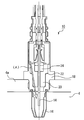
- FIG. 2 is a schematic diagram for explaining the configuration of air-fuel ratio sensors 8 and 10 according to Embodiment 1 of the present invention.
- the downstream sensor 10 will be described as an example, but in the first embodiment, the upstream sensor 8 and the downstream sensor 10 have the same configuration.
- the downstream sensor 10 includes an element unit 14.
- the element part 14 has a tubular structure with one end closed.
- An atmosphere side electrode (not shown) is formed on the inner surface of the element portion 14 formed in a tubular shape. Outside air flows into the inside of the tubular portion, whereby the atmosphere side electrode is in contact with the outside air.
- an exhaust side electrode (not shown) is formed on the outer surface of the tubular portion.
- the element unit 14 is installed in the exhaust path 4 while being covered with the cover 16.
- the cover 16 is provided with a plurality of vent holes (not shown) for introducing exhaust gas therein.
- the exhaust side electrode of the element portion 14 is exposed to the exhaust gas flowing into the cover 16 from the vent hole.
- the cover 16 is fixed to the wall surface 4 a of the exhaust path 4 by a housing 18. More specifically, the housing 18 is engaged with the cover 16 at a portion attached to the exhaust path 4, and the downstream sensor 10 is fixed and held on the exhaust path wall surface 4a with the upper edge portion of the cover 16 being caulked. Yes.
- the inside of the housing 18 is sealed with various members so that air does not leak inside the cover 16, and the element portion 14 is supported.
- a ceramic 20 is fitted inside the housing 18 to hold the element portion 14.
- a talc material 22 is embedded in the gap between the ceramic 20 and the housing 18.
- a glass 24 or the like is disposed on the ceramic 20. In this way, the atmosphere side electrode (inner tubular portion inner surface) side and the exhaust side electrode side of the downstream sensor 10 are shielded, and gas leakage is prevented between the atmosphere side and the exhaust gas side.
- the upstream sensor 8 and the downstream sensor 10 are installed in the exhaust path 4 and are exposed to high-temperature exhaust gas during use. For this reason, even if the atmosphere side and the exhaust gas side are separated from each other, as shown by the arrow (A) in FIG. The atmosphere leaks into the exhaust gas in the cover 16 although the amount is very small.
- the control executed by the control device 12 in the system of the first embodiment includes detection of an air-fuel ratio based on the outputs of the upstream sensor 8 and the downstream sensor 10 and various controls using the detection.
- detecting the air-fuel ratio a predetermined voltage is applied to each of the upstream sensor 8 and the downstream sensor 10.
- the upstream sensor 8 and the downstream sensor 10 emit an output that is a current value according to the concentration of the rich component and the lean component (hereinafter also referred to as “component concentration”) that affect the output of the air-fuel ratio sensor in the exhaust gas.
- component concentration concentration of the rich component and the lean component
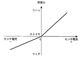
- FIG. 3 is a diagram for explaining the correspondence between the sensor output of the upstream sensor 8 and the air-fuel ratio according to the first embodiment of the present invention.
- the horizontal axis represents the sensor output
- the vertical axis represents the air-fuel ratio.
- the relationship between the sensor output of the upstream sensor 8 and the air-fuel ratio is the same as that of a normal limit current type sensor, and is theoretically obtained.
- the output zero point is set as a stoichiometric (theoretical air-fuel ratio) point, and as the output becomes smaller than zero, the corresponding air-fuel ratio becomes smaller, indicating a richer air-fuel ratio.
- the corresponding air-fuel ratio increases, indicating a leaner air-fuel ratio. Due to the characteristics of the air-fuel ratio sensor, the slope differs from the zero point, but the sensor output and the air-fuel ratio show a substantially proportional relationship.
- the upstream sensor 8 detects the exhaust gas discharged from the internal combustion engine 2 before passing through the three-way catalyst 6. Therefore, the exhaust gas component concentration is also high. Under such circumstances, even if some oxygen leakage occurs as described above, the sensor output is hardly affected, and oxygen leakage can be ignored. Therefore, for the upstream sensor 8, the relationship between the output and the air-fuel ratio as shown in the theoretical relationship of FIG. 3 is stored in the control device 12 as a function or a map. In actual use, the air-fuel ratio corresponding to the output of the upstream sensor 8 is detected based on this function, map, and the like.
- FIG. 4 is a diagram for explaining the relationship between the sensor output of the downstream sensor 10 of the first embodiment and the air-fuel ratio.
- the horizontal axis represents the sensor output
- the vertical axis represents the air-fuel ratio.
- the downstream sensor 10 is installed downstream of the three-way catalyst 6 and uses exhaust gas purified by the three-way catalyst 6 as a detection target.
- the purification rate of the three-way catalyst 6 is also high. Therefore, downstream of the three-way catalyst 6, there are very few components in the exhaust gas, and the component concentration is very thin. For this reason, in the vicinity of stoichiometry, oxygen that leaks very slightly affects the sensor output. As a result, in the vicinity of the stoichiometry, the output of the downstream sensor 10 is shifted to the lean side from the output corresponding to the actual air-fuel ratio of the exhaust gas.
- the air-fuel ratio with respect to the output of the downstream sensor 10 is the upstream sensor 8 (see the broken line (a) in FIG. 4).
- the relationship between the output and the air-fuel ratio is set so as to be shifted to the rich side as compared with. That is, the relationship between the output and the air-fuel ratio is set to be shifted to the rich side within a predetermined range including the zero point as shown in FIG.
- Such a relationship between the output of the downstream sensor 10 and the air-fuel ratio is obtained by experiments or the like. Specifically, for example, an evaluation gas having a very low concentration assuming the downstream of the three-way catalyst 6 in which 100% N 2 or rich gas and lean gas are completely burned at an equivalent ratio is supplied as an evaluation gas to the air-fuel ratio sensor. Then, the sensor output is detected. Similarly, the air-fuel ratio concentration is continuously changed from the gas to the rich side and the lean side within a predetermined range as shown in FIG. Based on the relationship between the output and the air-fuel ratio, the relationship between the output of the downstream sensor 10 and the air-fuel ratio in a predetermined range is determined. The determined relationship is stored in the control device 12 in advance.
- the outputs of the upstream sensor 8 and the downstream sensor 10 are detected, respectively, and the relationship between the respective outputs and the air-fuel ratio stored corresponding to the upstream sensor 8 and the downstream sensor 10 (FIG. 3, FIG. 4), the air-fuel ratio corresponding to each output is calculated.
- the relationship between the output of the downstream sensor 10 and the air-fuel ratio takes into account the influence of leakage in the vicinity of the stoichiometry. Therefore, even in the vicinity of the stoichiometric range, the air-fuel ratio can be detected more accurately according to the output of the downstream sensor 10. Therefore, for example, it is possible to improve the accuracy of air-fuel ratio feedback control executed based on both outputs of the upstream sensor 8 and the downstream sensor 10 and control such as catalyst deterioration determination.
- the relationship between the output and the air-fuel ratio is set according to the downstream sensor 10 .
- the relationship between the output and the air-fuel ratio is obtained by shifting the relationship between the same output and the air-fuel ratio to the rich side in the vicinity of the stoichiometry with respect to the correspondence relationship between the output of the upstream sensor 8 and the air-fuel ratio.
- the air-fuel ratio of the downstream sensor 10 is also directly obtained based on a preset relationship according to the detected output.
- the output of the downstream sensor 10 or the air-fuel ratio may be corrected in a direction in which the air-fuel ratio in the vicinity of the stoichiometry is shifted to the rich side.
- the upstream sensor 8 and the downstream sensor 10 calculate the air-fuel ratio based on the same relationship, that is, the relationship between the output of the upstream sensor 8 and the air-fuel ratio.
- the downstream air-fuel ratio can be obtained by correcting the calculated air-fuel ratio with the correction amount set according to the output of the downstream sensor 10.
- the output of the downstream sensor 10 is corrected so as to be an output on the rich side with respect to the detected output.
- the downstream air-fuel ratio can be obtained by calculating the air-fuel ratio based on the relationship between the same output as the upstream sensor 8 and the air-fuel ratio. The calculation method of the air-fuel ratio based on these outputs is similarly applied to the following embodiments.
- the present invention is not limited to such a configuration, and may be applied to, for example, a tandem catalyst having two catalysts arranged in series and integrally in the exhaust path 4.
- the installation positions of the air-fuel ratio sensors 8 and 10 are not necessarily limited to this. The same applies to the following embodiments.
- the upstream sensor 8 and the downstream sensor 10 are limit current type sensors having the same configuration.
- the sensor on the upstream side of the catalyst 6 may be one using another sensor that can detect the air-fuel ratio. The same applies to the following embodiments.
- FIG. The system and air-fuel ratio sensors 8 and 10 of the second embodiment have the same configuration as that shown in FIGS.
- the system of the second embodiment is the same as that of the first embodiment except that the relationship between the output near the stoichiometric position of the downstream sensor 10 and the air-fuel ratio is changed according to the temperature of the element unit 14.
- FIG. 5 is a diagram for explaining the relationship between the output of the downstream sensor 10 and the air-fuel ratio according to the second embodiment of the present invention.
- the horizontal axis indicates the sensor output
- the vertical axis indicates the air-fuel ratio.
- the solid line (a) represents the case where the temperature of the element unit 14 is a normal control temperature of 750 ° C.
- the solid line (b) represents the case where the temperature of the element unit 14 is a high temperature of 850 ° C.
- the leakage of air to the exhaust side (in the case 16) of the element portion 14 is caused by deformation caused by exposure of various sealed members to high temperatures. That is, the higher the temperature at which the air-fuel ratio sensors 8 and 10 are used, the greater the amount of air leakage. Therefore, when the temperature is high, the influence of oxygen leaked on the output of the downstream sensor 10 appears more greatly in the vicinity of the stoichiometry.
- the shift amount toward the rich side is changed according to the temperature of the element unit 14.
- two temperature regions are set with respect to the temperature of the element unit 14, that is, a temperature region having a normal control temperature center and a temperature region in the case of a higher temperature than that temperature region.
- the relationship between the output and the air-fuel ratio is determined for each temperature region.
- the shift amount to the rich side (see (a)) when the temperature of the element portion 14 is in the low temperature range is the case where the temperature of the element portion 14 is in the high temperature range.
- the specific shift amount according to such temperature can be obtained by performing an experiment for detecting the output by changing the concentration of exhaust gas to be supplied for each downstream sensor 10 under various temperature environments. it can.
- the relationship obtained in this way is stored in the control device 12 as a relational expression, a map, or the like that defines the relationship between temperature, output, and air-fuel ratio.
- the downstream sensor 10 is actually installed in the exhaust path 4 of the internal combustion engine 2 and used for air-fuel ratio control or the like, the impedance of the element unit 14 is detected, and the temperature of the element unit 14 is estimated based on this.
- the air-fuel ratio is calculated according to the map stored in the control device 12 according to the estimated temperature and the output value of the downstream sensor 10.
- the relationship between the output of the downstream sensor 10 and the air-fuel ratio is defined in consideration of the difference in oxygen leakage due to the difference in temperature. Therefore, the influence of the output due to the leaked oxygen can be suppressed to a smaller level, the air-fuel ratio can be grasped more accurately on the downstream side of the three-way catalyst, and various controls can be executed with high accuracy.
- the case where the temperature range with respect to the temperature of the element portion is set and the relationship between the output and the air-fuel ratio is determined in each case has been described.
- the air-fuel ratio on the rich side is calculated when the temperature of the element portion 14 is in the high temperature range, compared to when it is in the low temperature range.
- the method for setting the output and the air-fuel ratio with respect to the temperature of the element portion is not limited to the one in which two temperature regions are determined in this way. For example, three or more temperature ranges are set, and the relationship between the output and the air-fuel ratio shifted corresponding to each temperature range is set, and the shift is gradually made rich. It may be.
- the air-fuel ratio may be gradually shifted to the rich side steplessly as the temperature of the element unit 14 increases.
- a coefficient that shifts the relationship between the basic output of the downstream sensor 10 and the air-fuel ratio (see FIG. 4) according to the temperature of the element unit 14 is installed, and the coefficient according to the temperature is The air / fuel ratio may be calculated according to the temperature from the relationship between the output and the air / fuel ratio.
- the air-fuel ratio is calculated according to the relationship between the air-fuel ratio of the upstream sensor 8 and the downstream sensor 10 with the same output, and the output of the downstream sensor 10 or the calculated air-fuel ratio is determined according to the temperature. Further correction may be made. In this case as well, the leak amount can be taken into consideration by correcting the output of the downstream sensor 10 or the air-fuel ratio stepwise or steplessly according to the temperature.
- the present invention is not limited to this, and the temperature may be detected by other means. Specifically, for example, a temperature sensor may be directly embedded in the element unit 14 to detect the temperature.
- Embodiment 3 The system, the upstream sensor 8 and the downstream sensor 10 of the third embodiment have the same configuration as that described in FIGS.
- the system of the third embodiment performs the same control as the system of the first embodiment, except that the air-fuel ratio in the vicinity of the stoichiometry is shifted according to the exhaust gas flow rate.
- FIG. 6 is a diagram for explaining the relationship between the output for each exhaust gas flow rate and the air-fuel ratio of the downstream sensor 10 according to the third embodiment.
- the horizontal axis represents the output
- the vertical axis represents the air-fuel ratio. Further, the relationship when the exhaust gas flow rate increases from the solid line (a) side to the solid line (c) side is shown.
- the amount of shift to the rich side in the predetermined region near the stoichiometry decreases. That is, when an output having a predetermined region is detected, the air-fuel ratio obtained based on the output is shifted to the richer side than the air-fuel ratio corresponding to the same output of the upstream sensor 8, but the shift amount Is smaller than when the exhaust gas flow rate is small (solid lines (a) and (b)).
- FIG. 7 is a diagram for explaining a map that defines the relationship among the intake air amount, sensor output, and air-fuel ratio in the third embodiment. In FIG. 7, only a portion corresponding to a predetermined area in the vicinity of the stoichiometric map is shown.
- the intake air amount is used as a value having a correlation with the exhaust gas flow rate.
- the intake air amount is divided into five regions, and the air-fuel ratio corresponding to the output is determined for each region.
- the required air-fuel ratio is set to be on the lean side as the intake air amount is larger for the same output. Further, when the output becomes a value on the rich side or the lean side from the vicinity of the stoichiometric range, the air-fuel ratio obtained corresponding to the output does not change even if the intake air amount changes. On the other hand, as the output becomes closer to the stoichiometry, the change amount according to the intake air amount of the air-fuel ratio obtained from the same output is set to be larger.
- the map defining such a specific relationship can be set for each downstream sensor 10 by performing an experiment or the like for detecting the output while changing the flow rate of the sample gas and the air-fuel ratio.
- the determined map is stored in the control device 12 in advance.
- FIG. 8 is a flowchart for explaining a control routine executed by the control device 12 in the third embodiment of the present invention.
- the process of FIG. 8 is a subroutine that is executed when detection of the air-fuel ratio is requested.
- the output of the downstream sensor 10 is acquired (S102).
- the intake air amount is acquired (S104).
- the intake air amount is detected based on, for example, the output of an air flow meter (not shown) installed in the intake system of the internal combustion engine 2.
- the air-fuel ratio is calculated (S106).
- the air-fuel ratio is calculated according to a map stored in advance in the control device 12 according to the sensor output acquired in step S102 and the intake air amount acquired in step S104. Thereafter, the current process ends.
- the air-fuel ratio based on the output of the downstream sensor 10 takes into consideration the influence of oxygen leak in the vicinity of the stoichiometry in accordance with the intake air amount (exhaust gas flow rate). Therefore, the air-fuel ratio downstream of the three-way catalyst 6 can be detected more accurately, and the control accuracy based on the air-fuel ratio according to the output of the downstream sensor 10 can be improved.
- the intake air amount is used as a value having a correlation with the exhaust gas flow rate and a map corresponding to the intake air amount is set has been described.
- the present invention is not limited to this, and other parameters having a correlation with the exhaust gas flow rate can be used.
- a sensor may be installed in the vicinity of the downstream sensor 10 to directly detect the exhaust gas flow rate and use it.
- the case where five regions are set for the exhaust gas flow rate and a map that defines the relationship between each region and the output and the air-fuel ratio has been described.
- the rich-side air-fuel ratio is calculated as compared with the case where the exhaust gas flow rate is in a region where the exhaust gas flow rate is larger than that region.
- the number of regions with respect to the exhaust gas flow rate is not limited to five, and may be divided into two or more regions.
- the amount of shift of the air-fuel ratio to the rich side may be set such that the amount of shift of the air-fuel ratio to the rich side gradually decreases steplessly as the exhaust gas flow rate increases.
- a coefficient that shifts the relationship between the basic output of the downstream sensor 10 and the air-fuel ratio (see FIG. 4) according to the exhaust gas flow rate is installed, and the coefficient according to the exhaust gas flow rate is An air-fuel ratio corresponding to the exhaust gas flow rate may be calculated from the relationship between the output and the air-fuel ratio.
- the air-fuel ratio is calculated according to the relationship between the air-fuel ratio of the upstream sensor 8 and the downstream sensor 10 and the same output, and the output of the downstream sensor 10 or the calculated air-fuel ratio is used as the exhaust gas flow rate. It may be corrected accordingly. Also in this case, the leak amount can be considered by correcting the output or the air-fuel ratio of the downstream sensor 10 stepwise or steplessly according to the exhaust gas flow rate.
- Embodiment 3 by combining the above-described Embodiment 3 and Embodiment 2, the relationship between the output of the downstream sensor 10 and the air-fuel ratio in the vicinity of the stoichiometry in accordance with the temperature of the element unit 14 and the exhaust gas flow rate, It can also be shifted to the rich side.
- Embodiment 4 FIG.
- the system and air-fuel ratio sensors 8 and 10 of the fourth embodiment have the same configuration as that described in FIGS.
- the system of the fourth embodiment performs the same control as the system of the first embodiment except that the relationship between the output and the air-fuel ratio is shifted according to the temperature of the exhaust gas.
- the system of the second embodiment described above detects the temperature of the element unit 14 by detecting the impedance of the element unit 14, and the shift amount is different depending on whether the temperature is high or low. This is a control for dealing with the fact that the leak amount increases as the temperature of the downstream sensor 10 increases.
- the impedance of the element unit 14 changes over time due to the use of the downstream sensor 10. For this reason, an error may occur in the temperature of the element unit 14 calculated from the impedance.
- the temperature change of the airtight portions (such as the housing 18) of the air-fuel ratio sensors 8, 10 has a certain degree of correlation with the exhaust gas temperature, and can be estimated from the exhaust gas temperature. Therefore, in the fourth embodiment, control is performed to obtain the exhaust gas temperature based on the output of the exhaust temperature sensor (not shown) and set the shift amount accordingly.
- the airtight part of the downstream sensor 10 is configured inside the sensor in the vicinity of the screw part for attaching the sensor to the exhaust path 4. Therefore, the detected exhaust gas temperature is not used directly, but the value after the annealing process or the value after the calculation of the first response delay adapted in consideration of the heat transfer of the exhaust path, etc. It shall be used as
- TEXS i (TEXS i-1 xn + TEX i ) / (n + 1) (1)
- TEXS i and TEXS i-1 are the smoothed values of the exhaust gas temperature calculated at the i-th (current) and i-1-th (previous) respectively, and TEX i is obtained for the i-th (current).
- Exhaust gas temperature, and n is the number of annealing.
- TEXS_2 K (1-et / T ) (2)
- k is a gain (constant)
- e is an exponential function
- t time
- T is a time constant.
- FIG. 9 is a diagram for explaining the relationship between the sensor output and the air-fuel ratio for each exhaust gas temperature in the fourth embodiment of the present invention.
- the horizontal axis represents the sensor output
- the vertical axis represents the air-fuel ratio.
- the solid lines (d) to (f) represent the relationship between the sensor output and the air-fuel ratio at each exhaust gas temperature, and the exhaust gas temperature increases from the solid line (d) side to the (f) side. Is shown.
- the air-fuel ratio required for the same output having a predetermined region near the stoichiometric range is set so that the downstream sensor 10 has a richer value than the upstream sensor 8. ing. Furthermore, as shown by solid lines (f) to (d) in FIG. 9, the air-fuel ratio corresponding to the same output is higher when the exhaust gas temperature is higher than when the exhaust gas temperature is lower (see the solid line (d)) (see FIG. 9). The solid line (see f) is shifted to the rich side.
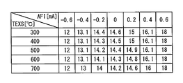
- FIG. 10 is a diagram for explaining a map that defines the relationship among exhaust gas temperature, sensor output, and air-fuel ratio in the fourth embodiment. Note that FIG. 10 shows only a portion corresponding to a predetermined area near the stoichiometric map.
- the air-fuel ratio is set to be richer as the exhaust gas temperature is higher in the region for the same output. Further, when the output is biased toward the rich side or the lean side, the air-fuel ratio determined corresponding to the output does not change even when the exhaust gas temperature changes, and shows a constant value. On the other hand, the closer the output is to stoichiometric (0), the larger the amount of change of the air-fuel ratio determined from the same output in accordance with the exhaust gas temperature.
- FIG. 10 shows a map that defines a specific relationship between the exhaust gas temperature, the output, and the air-fuel ratio. This is an experiment in which the output is detected by supplying a sample gas whose concentration is changed at each exhaust gas temperature. It can be set by performing etc. The set map is stored in the control device 12 in advance.
- FIG. 11 is a flowchart for explaining a control routine executed by the control device 12 in the fourth embodiment of the present invention.
- the process of FIG. 11 is a subroutine that is executed when there is a request for detection of the air-fuel ratio.
- the value of the annealing process or the value after the calculation of the first response delay is calculated with respect to the detected exhaust gas temperature (S206). These values are calculated according to Equation 1 or Equation 2 above. This value is used as the exhaust gas temperature in the following calculation of the air-fuel ratio.
- the air-fuel ratio is calculated (S208).
- the air-fuel ratio is calculated based on a map stored in advance in the control device 12 according to the sensor output acquired in step S202 and the exhaust gas temperature acquired in step S206. Thereafter, the current process ends.
- the temperature of the airtight portion of the downstream sensor 10 is estimated to some extent based on the exhaust gas temperature, so that it is not affected by the shift in impedance due to deterioration with time of the downstream sensor.
- the air-fuel ratio can be detected according to the oxygen leak amount of the downstream sensor 10.
- the air-fuel ratio may be calculated by directly using the detected exhaust gas temperature without performing such processing.
- the temperature related to the temperature of the hermetic portion is not limited to the exhaust gas temperature.
- the shift amount may be set according to the catalyst temperature of the three-way catalyst.
- the exhaust gas temperature may be estimated from the control parameters of the internal combustion engine 2.
- the fourth embodiment a case has been described in which five regions are set for the exhaust gas temperature and a map that defines the relationship between each region and the output and the air-fuel ratio is used.
- the rich-side air-fuel ratio is calculated as compared to when the exhaust gas temperature is in a region lower than that region.
- the number of regions with respect to the exhaust gas temperature is not limited to five, and the number of regions can be set as appropriate.
- the amount of shift of the air-fuel ratio to the rich side may be set so that the amount of shift of the air-fuel ratio to the rich side gradually increases steplessly as the exhaust gas temperature increases.
- a coefficient that shifts the relationship between the basic output of the downstream sensor 10 and the air-fuel ratio (see FIG. 4) according to the exhaust gas temperature is installed, and the coefficient according to the exhaust gas temperature is An air-fuel ratio corresponding to the exhaust gas temperature may be calculated from the relationship between the output and the air-fuel ratio.
- the air-fuel ratio is calculated according to the relationship between the air-fuel ratio of the upstream sensor 8 and the downstream sensor 10 and the same output, and the output of the downstream sensor 10 or the calculated air-fuel ratio is It may be corrected according to the exhaust gas temperature.
- the leak amount can be taken into consideration by correcting the output of the downstream sensor 10 or the air-fuel ratio stepwise or steplessly according to the exhaust gas temperature.
- the air-fuel ratio is shifted according to the temperature of the element section 14, in the third embodiment, the air-fuel ratio is shifted according to the exhaust gas flow rate, and in the fourth embodiment, the exhaust gas temperature is shifted.
- the case where the air-fuel ratio is shifted according to the above has been described.
- the present invention is not limited to performing these separately and independently, and the air-fuel ratio may be detected by combining these two or all of them.
Landscapes
- Engineering & Computer Science (AREA)
- Chemical & Material Sciences (AREA)
- Combustion & Propulsion (AREA)
- Mechanical Engineering (AREA)
- General Engineering & Computer Science (AREA)
- Materials Engineering (AREA)
- Health & Medical Sciences (AREA)
- Chemical Kinetics & Catalysis (AREA)
- Toxicology (AREA)
- Electrical Control Of Air Or Fuel Supplied To Internal-Combustion Engine (AREA)
- Combined Controls Of Internal Combustion Engines (AREA)
Abstract
Description
[本実施の形態のシステムの全体構成]
図1は、この発明の実施の形態におけるシステムの全体構成について説明するための模式図である。図1のシステムは車両等に搭載されて用いられる。図1において、内燃機関2の排気経路4には三元触媒6が設置されている。三元触媒6は内燃機関2から排出される一酸化炭素(CO)及び炭化水素(HC)を酸化すると共に、窒素酸化物(NOx)を還元することにより、排気ガスを浄化する触媒である。
図2は、本発明の実施の形態1の空燃比センサ8、10の構成について説明するための模式図である。図2では、下流センサ10を例にとって説明するが、本実施の形態1において上流センサ8と下流センサ10とは同一の構成を有している。
本実施の形態1のシステムにおいて制御装置12が実行する制御には、上流センサ8及び下流センサ10それぞれの出力に基づく空燃比の検出と、それを用いた種々の制御が含まれる。空燃比の検出において、上流センサ8及び下流センサ10それぞれには、所定の電圧が印加される。上流センサ8及び下流センサ10は、排気ガス中の空燃比センサの出力に影響を与えるリッチ成分及びリーン成分の濃度(以下「成分濃度」とも称する)に応じ、電流値である出力を発する。この電流値と空燃比とは、理論的には相関を有しており、この関係に基づいて、センサ出力から空燃比が求められる。
図4は、本実施の形態1の下流センサ10のセンサ出力と空燃比との関係を説明するための図である。図4において、横軸はセンサ出力、縦軸は空燃比を表している。
実施の形態2のシステム及び空燃比センサ8、10は、図1、図2に示したものと同様の構成を有している。実施の形態2のシステムは、下流センサ10のストイキ近傍の出力と空燃比との関係性が、素子部14の温度に応じて変更される点を除き、実施の形態1と同じものである。
実施の形態3のシステム及び上流センサ8、下流センサ10は、図1、図2に説明したものと同一の構成を有している。実施の形態3のシステムは、排気ガスの流量に応じてストイキ近傍での空燃比をシフトさせる点を除き、実施の形態1のシステムと同じ制御を行う。
実施の形態4のシステム及び空燃比センサ8、10は、図1、図2に説明したものと同一の構成のものである。実施の形態4のシステムは、出力と空燃比との関係を、排気ガスの温度に応じてシフトさせる点を除き、実施の形態1のシステムと同様の制御を行う。
TEXSi=(TEXSi-1×n+TEXi)/(n+1) ・・・・(1)
ここで、TEXSi、TEXSi-1は、それぞれi回目(今回)、i-1回目(前回)に演算された排気ガス温度のなまし値であり、TEXiは、i回目(今回)取得した排気ガス温度であり、nはなまし回数である。
TEXS_2=K(1-et/T) ・・・・(2)
ここで、kはゲイン(定数)、eはイクスポネンシャル関数(exponential function)、tは時間、Tは時定数である。
4 排気経路
4a 排気経路壁面
6 三元触媒
8 上流センサ(空燃比センサ)
10 下流センサ(空燃比センサ)
12 制御装置
14 素子部
16 カバー
18 ハウジング
20 セラミック
22 タルク材
24 ガラス
Claims (22)
- 内燃機関の排気経路の触媒より下流側に設置された限界電流式の空燃比センサである下流センサの出力を検出する検出手段と、
前記下流センサの出力に応じて、前記触媒下流の排気ガスの空燃比を演算手段と、
を備え、
前記下流センサの出力が、理論空燃比に応じた出力を含む所定範囲内にある場合、
前記下流センサの出力と前記演算手段により演算される空燃比との関係は、内燃機関の排気経路の触媒よりも上流側に設置される、前記下流センサと同様のセンサである上流センサの出力と空燃比との対応関係よりも、リッチ側にずれたものであることを特徴とする空燃比検出装置。 - 前記演算手段により演算される空燃比は、
前記下流センサの出力が、前記所定範囲内にある場合、
前記上流センサの前記対応関係において該出力と同じ値の出力に対応する空燃比よりも、リッチ側の値であることを特徴とする請求項1に記載の空燃比検出装置。 - 前記下流センサの出力が、前記所定範囲内にある場合、
前記下流センサの出力に応じて前記演算手段により演算される空燃比と、前記上流センサの前記対応関係に基づいて上流センサの出力に応じて演算される空燃比とが同一であるとき、前記下流センサの出力の値は前記上流センサの出力の値よりもリーン側の値であることを特徴とする請求項1又は2に記載の空燃比検出装置。 - 前記下流センサの素子部の温度を検出又は推定する手段を、更に備え、
前記下流センサの出力が前記所定範囲内にある場合において、
前記下流センサの出力と該出力に基づいて演算される空燃比との関係は、前記素子部の温度が高い場合、前記素子部の温度が低い場合よりもリッチ側にずれたものであることを特徴とする請求項1から3のいずれか1項に記載の空燃比検出装置。 - 前記内燃機関の排気経路に排出される排気ガス流量を検出又は推定する手段を、更に備え、
前記下流センサの出力が前記所定範囲内にある場合において、
前記下流センサの出力と該出力に基づいて演算される空燃比との関係は、前記排気ガス流量が少ない場合、前記排気ガス流量が多い場合よりも、リッチ側にずれたものであることを特徴とする請求項1から4のいずれか1項に記載の空燃比検出装置。 - 前記内燃機関の排気経路に排出される排気ガス温度を検出又は推定する手段を、更に備え、
前記下流センサの出力が前記所定範囲内にある場合において、
前記下流センサの出力と該出力に基づいて演算される空燃比との関係は、前記排気ガス温度が高い場合、前記排気ガス温度が低い場合よりもリッチ側にずれたものであることを特徴とする請求項1から5のいずか1項に記載の空燃比検出装置。 - 前記演算手段は、
前記上流センサの前記対応関係と同様の関係に基づいて、前記下流センサの出力に応じた空燃比を演算する第1手段と、
前記下流センサの出力が前記所定範囲内にある場合、前記演算された空燃比をリッチ側の空燃比となるように補正する第2手段と、
を備えることを特徴とする請求項1に記載の空燃比検出装置。 - 前記下流センサの素子部の温度を検出又は推定する手段を、更に備え、
前記第2手段は、前記素子部の温度が高い場合、前記素子部の温度が低い場合よりも、該空燃比をリッチ側に補正することを特徴とする請求項7に記載の空燃比検出装置。 - 前記内燃機関から排出される排気ガス流量を検出又は推定する手段を、更に備え、
前記第2手段は、前記排気ガス流量が少ない場合、前記排気ガス流量が多い場合よりも、該空燃比をリッチ側に補正することを特徴とする請求項7または8に記載の空燃比検出装置。 - 前記内燃機関から排気される排気ガスの温度を検出又は推定する手段を、更に備え、
前記第2手段は、前記排気ガス温度が高い場合、前記排気ガス温度が低い場合よりも、該空燃比をリッチ側に補正することを特徴とする特徴とする請求項7から9のいずれか1項に記載の空燃比検出装置。 - 前記演算手段は、
前記下流センサの出力が前記所定範囲内にある場合に、該出力をリッチ側の値に補正する第3手段と、
前記補正された出力に応じて、前記上流センサの前記対応関係と同様の関係に基づいて空燃比を演算する第4手段と、
を備えることを特徴とする請求項1に記載の空燃比検出装置。 - 前記下流センサの素子部の温度を検出又は推定する手段を、更に備え、
前記第3手段は、
前記素子部の温度が高い場合、前記素子部の温度が低い場合よりも、該出力をリッチ側に補正することを特徴とする請求項11に記載の空燃比検出装置。 - 前記内燃機関から排出される排気ガス流量を検出又は推定する手段を、更に備え、
前記第3手段は、前記排気ガス流量が少ない場合、前記排気ガス流量が多い場合よりも、該出力をリッチ側に補正することを特徴とする請求項11または12に記載の空燃比検出装置。 - 前記内燃機関から排気される排気ガスの温度を検出又は推定する手段を、更に備え、
前記第3手段は、前記排気ガス温度が高い場合、前記排気ガス温度が低い場合よりも、該出力をリッチ側に補正することを特徴とする特徴とする請求項11から13のいずれか1項に記載の空燃比検出装置。 - 内燃機関の排気経路の触媒より下流側に設置された限界電流式の空燃比センサである下流センサの出力を検出し、前記下流センサの出力に応じて、前記触媒下流の排気ガスの空燃比を演算する空燃比検出方法において、
前記下流センサの出力が、理論空燃比に対応する出力を含む所定範囲内にある場合、
前記下流センサの出力と該出力に応じて演算される空燃比との関係は、内燃機関の排気経路の触媒よりも上流側に設置される、前記下流センサと同様のセンサである上流センサの出力と空燃比との対応関係より、リッチ側にずれたものであることを特徴とする空燃比検出方法。 - 前記下流センサの出力が、前記所定範囲内にある場合、
該出力に応じて演算される空燃比は、前記上流センサの前記対応関係において該出力と同じ値の出力に対応する空燃比よりも、リッチ側の値であることを特徴とする請求項15に記載の空燃比検出方法。 - 前記下流センサの出力が前記所定範囲内にある場合において、
前記下流センサの出力に応じて演算される空燃比と、前記上流センサの前記対応関係に基づいて前記上流センサの出力に応じて演算された空燃比とが同一であるとき、前記下流センサの出力の値が、前記上流センサの出力の値よりもリーン側の値であることを特徴とする請求項15に記載の空燃比検出方法。 - 前記上流センサの対応関係と同様の関係に基づいて、前記下流センサの出力に応じた空燃比を演算し、
前記下流センサの出力が前記所定範囲内にある場合、前記演算された空燃比を、リッチ側に補正する
ことを特徴とする請求項15に記載の空燃比検出方法。 - 前記下流センサの出力が前記所定範囲内にある場合に、該出力をリッチ側の値に補正し、
前記補正された出力に応じて、前記上流センサの前記対応関係と同様の関係に基づいて空燃比を演算する、
ことを特徴とする請求項15に記載の空燃比検出方法。 - 前記下流センサの素子部の温度を検出又は推定し、
前記下流センサの出力が前記所定範囲内にある場合において、前記下流センサの出力に応じて演算される空燃比は、前記素子部の温度が高い場合、前記素子部の温度が低い場合に該出力と同じ値の出力に応じて演算される空燃比よりも、リッチ側の値とする
ことを特徴とする請求項15から19のいずれか1項に記載の空燃比検出方法。 - 前記内燃機関の排気経路に排出される排気ガス流量を検出又は推定し、
前記下流センサの出力が前記所定範囲内にある場合において、
前記下流センサの出力に応じて演算される空燃比は、前記排気ガス流量が少ない場合、前記排気ガス流量が多い場合に該出力と同じ値の出力に応じて演算される空燃比よりも、リッチ側の値とする
ことを特徴とする請求項15から20のいずれか1項に記載の空燃比検出方法。 - 前記内燃機関の排気経路に排出される排気ガス温度を検出又は推定し、
前記下流センサの出力が前記所定範囲内にある場合において、
前記下流センサの出力に応じた空燃比は、前記排気ガス温度が高い場合、前記排気ガス温度が低い場合に該出力と同じ値の出力に応じて演算される空燃比よりも、リッチ側の値とする
ことを特徴とする請求項15から21のいずか1項記載の空燃比検出方法。
Priority Applications (4)
| Application Number | Priority Date | Filing Date | Title |
|---|---|---|---|
| EP11876060.2A EP2784293A4 (en) | 2011-11-24 | 2011-11-24 | DEVICE FOR DETERMINING THE AIR-FUEL RATIO A METHOD FOR DETERMINING THE AIR-FUEL RATIO |
| JP2013545716A JP5835343B2 (ja) | 2011-11-24 | 2011-11-24 | 空燃比検出装置及び空燃比検出方法 |
| PCT/JP2011/077054 WO2013076842A1 (ja) | 2011-11-24 | 2011-11-24 | 空燃比検出装置及び空燃比検出方法 |
| US14/360,092 US9890730B2 (en) | 2011-11-24 | 2011-11-24 | Air-fuel ratio detection device and air-fuel ratio detection method |
Applications Claiming Priority (1)
| Application Number | Priority Date | Filing Date | Title |
|---|---|---|---|
| PCT/JP2011/077054 WO2013076842A1 (ja) | 2011-11-24 | 2011-11-24 | 空燃比検出装置及び空燃比検出方法 |
Publications (1)
| Publication Number | Publication Date |
|---|---|
| WO2013076842A1 true WO2013076842A1 (ja) | 2013-05-30 |
Family
ID=48469320
Family Applications (1)
| Application Number | Title | Priority Date | Filing Date |
|---|---|---|---|
| PCT/JP2011/077054 Ceased WO2013076842A1 (ja) | 2011-11-24 | 2011-11-24 | 空燃比検出装置及び空燃比検出方法 |
Country Status (4)
| Country | Link |
|---|---|
| US (1) | US9890730B2 (ja) |
| EP (1) | EP2784293A4 (ja) |
| JP (1) | JP5835343B2 (ja) |
| WO (1) | WO2013076842A1 (ja) |
Families Citing this family (1)
| Publication number | Priority date | Publication date | Assignee | Title |
|---|---|---|---|---|
| CN114720133B (zh) * | 2022-04-19 | 2024-06-18 | 潍柴动力股份有限公司 | 一种大功率气体机空燃比的标定方法及标定系统 |
Citations (10)
| Publication number | Priority date | Publication date | Assignee | Title |
|---|---|---|---|---|
| JPH1193744A (ja) | 1997-09-19 | 1999-04-06 | Toyota Motor Corp | 内燃機関の排気浄化装置 |
| JP2001234789A (ja) * | 2000-02-23 | 2001-08-31 | Nissan Motor Co Ltd | 内燃機関の空燃比制御装置 |
| JP2003097334A (ja) | 2001-09-19 | 2003-04-03 | Toyota Motor Corp | 内燃機関の触媒劣化検出装置 |
| JP2005248914A (ja) | 2004-03-08 | 2005-09-15 | Toyota Motor Corp | 内燃機関の空燃比制御装置 |
| JP2006002579A (ja) | 2004-06-15 | 2006-01-05 | Nissan Motor Co Ltd | 内燃機関の空燃比制御装置 |
| JP2006010583A (ja) | 2004-06-28 | 2006-01-12 | Denso Corp | ガス濃度検出装置 |
| JP2006291893A (ja) | 2005-04-13 | 2006-10-26 | Toyota Motor Corp | 酸素センサ及び空燃比制御システム |
| JP2007232709A (ja) * | 2006-02-03 | 2007-09-13 | Toyota Motor Corp | 空燃比センサの故障検出装置 |
| JP2008014670A (ja) * | 2006-07-03 | 2008-01-24 | Toyota Motor Corp | 排気ガスセンサの異常診断装置 |
| JP2009024613A (ja) * | 2007-07-20 | 2009-02-05 | Toyota Motor Corp | 内燃機関の触媒の劣化度合い取得装置 |
Family Cites Families (23)
| Publication number | Priority date | Publication date | Assignee | Title |
|---|---|---|---|---|
| DE3809154C1 (ja) * | 1988-03-18 | 1988-12-08 | Robert Bosch Gmbh, 7000 Stuttgart, De | |
| JPH07116931B2 (ja) * | 1991-12-19 | 1995-12-18 | トヨタ自動車株式会社 | 内燃機関の触媒劣化判別装置 |
| JP3179920B2 (ja) * | 1993-02-12 | 2001-06-25 | 株式会社日立製作所 | 内燃機関の触媒診断装置 |
| US5379590A (en) * | 1993-10-06 | 1995-01-10 | Ford Motor Company | Air/fuel control system with hego current pumping |
| US5528899A (en) * | 1993-12-13 | 1996-06-25 | Nippondenso Co., Ltd. | Air-fuel ratio control apparatus for internal combustion engines |
| US5497618A (en) * | 1994-09-30 | 1996-03-12 | Ford Motor Company | Air/fuel control system with catalytic converter monitoring |
| JP3262682B2 (ja) * | 1994-11-14 | 2002-03-04 | 株式会社豊田中央研究所 | 空燃比センサ特性解析装置 |
| US5845489A (en) * | 1995-11-08 | 1998-12-08 | Denso Corporation | Abnormality detector for air-fuel ratio control system |
| US6021758A (en) * | 1997-11-26 | 2000-02-08 | Cummins Engine Company, Inc. | Method and apparatus for engine cylinder balancing using sensed engine speed |
| EP1128045B1 (en) | 2000-02-23 | 2005-12-28 | Nissan Motor Co., Ltd. | Engine air-fuel ratio controller |
| US6739177B2 (en) * | 2001-03-05 | 2004-05-25 | Toyota Jidosha Kabushiki Kaisha | Combustible-gas sensor, diagnostic device for intake-oxygen concentration sensor, and air-fuel ratio control device for internal combustion engines |
| US7198952B2 (en) | 2001-07-18 | 2007-04-03 | Toyota Jidosha Kabushiki Kaisha | Catalyst deterioration detecting apparatus and method |
| DE10254704A1 (de) * | 2002-11-23 | 2004-06-17 | Adam Opel Ag | Verfahren zur Diagnose der Funktionsfähigkeit einer Abgas-Katalysatoreinheit |
| JP4093190B2 (ja) * | 2003-03-31 | 2008-06-04 | 株式会社デンソー | ガス濃度検出装置 |
| JP2005133620A (ja) | 2003-10-29 | 2005-05-26 | Toyota Motor Corp | 内燃機関の排気浄化装置 |
| JP2007032438A (ja) * | 2005-07-27 | 2007-02-08 | Toyota Motor Corp | 内燃機関の空燃比制御装置 |
| JP2007212405A (ja) * | 2006-02-13 | 2007-08-23 | Denso Corp | ガスセンサ、並びにこれを用いたガス濃度検出システム及びその製造方法 |
| JP4329799B2 (ja) * | 2006-09-20 | 2009-09-09 | トヨタ自動車株式会社 | 内燃機関の空燃比制御装置 |
| JP2009002251A (ja) * | 2007-06-22 | 2009-01-08 | Toyota Motor Corp | 内燃機関の空燃比制御装置 |
| JP5062529B2 (ja) * | 2008-02-28 | 2012-10-31 | トヨタ自動車株式会社 | 触媒の劣化を診断するための装置及び方法 |
| US8509984B2 (en) * | 2009-01-28 | 2013-08-13 | Toyota Jidosha Kabushiki Kaisha | Monitoring apparatus for a multi-cylinder internal combustion engine |
| US8670917B2 (en) * | 2009-10-06 | 2014-03-11 | Toyota Jidosha Kabushiki Kaisha | Air-fuel-ratio imbalance determination apparatus for internal combustion engine |
| JP2011163229A (ja) * | 2010-02-10 | 2011-08-25 | Toyota Motor Corp | 多気筒内燃機関の気筒間空燃比インバランス判定装置 |
-
2011
- 2011-11-24 US US14/360,092 patent/US9890730B2/en not_active Expired - Fee Related
- 2011-11-24 EP EP11876060.2A patent/EP2784293A4/en not_active Withdrawn
- 2011-11-24 WO PCT/JP2011/077054 patent/WO2013076842A1/ja not_active Ceased
- 2011-11-24 JP JP2013545716A patent/JP5835343B2/ja not_active Expired - Fee Related
Patent Citations (10)
| Publication number | Priority date | Publication date | Assignee | Title |
|---|---|---|---|---|
| JPH1193744A (ja) | 1997-09-19 | 1999-04-06 | Toyota Motor Corp | 内燃機関の排気浄化装置 |
| JP2001234789A (ja) * | 2000-02-23 | 2001-08-31 | Nissan Motor Co Ltd | 内燃機関の空燃比制御装置 |
| JP2003097334A (ja) | 2001-09-19 | 2003-04-03 | Toyota Motor Corp | 内燃機関の触媒劣化検出装置 |
| JP2005248914A (ja) | 2004-03-08 | 2005-09-15 | Toyota Motor Corp | 内燃機関の空燃比制御装置 |
| JP2006002579A (ja) | 2004-06-15 | 2006-01-05 | Nissan Motor Co Ltd | 内燃機関の空燃比制御装置 |
| JP2006010583A (ja) | 2004-06-28 | 2006-01-12 | Denso Corp | ガス濃度検出装置 |
| JP2006291893A (ja) | 2005-04-13 | 2006-10-26 | Toyota Motor Corp | 酸素センサ及び空燃比制御システム |
| JP2007232709A (ja) * | 2006-02-03 | 2007-09-13 | Toyota Motor Corp | 空燃比センサの故障検出装置 |
| JP2008014670A (ja) * | 2006-07-03 | 2008-01-24 | Toyota Motor Corp | 排気ガスセンサの異常診断装置 |
| JP2009024613A (ja) * | 2007-07-20 | 2009-02-05 | Toyota Motor Corp | 内燃機関の触媒の劣化度合い取得装置 |
Non-Patent Citations (1)
| Title |
|---|
| See also references of EP2784293A4 |
Also Published As
| Publication number | Publication date |
|---|---|
| US20140316678A1 (en) | 2014-10-23 |
| US9890730B2 (en) | 2018-02-13 |
| JPWO2013076842A1 (ja) | 2015-04-27 |
| EP2784293A4 (en) | 2015-08-12 |
| JP5835343B2 (ja) | 2015-12-24 |
| EP2784293A1 (en) | 2014-10-01 |
Similar Documents
| Publication | Publication Date | Title |
|---|---|---|
| US8899015B2 (en) | Catalyst degradation detection device | |
| JP5556962B2 (ja) | センサの特性補正装置 | |
| JP6056864B2 (ja) | 内燃機関の制御装置 | |
| JP2019044611A (ja) | 内燃機関の排気装置 | |
| JP4631517B2 (ja) | 酸素センサ及び空燃比制御システム | |
| US20170152807A1 (en) | Engine control apparatus | |
| JP5835343B2 (ja) | 空燃比検出装置及び空燃比検出方法 | |
| JP4647393B2 (ja) | 空燃比センサの異常診断装置 | |
| JP5851569B1 (ja) | エンジン制御装置 | |
| JP5783091B2 (ja) | 空燃比センサの出力補正装置 | |
| JP5991259B2 (ja) | 排気ガス成分検出装置 | |
| US9347352B2 (en) | Correction device for air/fuel ratio sensor | |
| JP5704038B2 (ja) | 空燃比センサの補正装置 | |
| US11384677B2 (en) | State estimation apparatus | |
| JP2006307716A (ja) | 内燃機関の空燃比制御装置 | |
| JP5182160B2 (ja) | 内燃機関の空燃比制御装置 | |
| JP2008286122A (ja) | 空燃比を検出する装置 | |
| JP2007247412A (ja) | 内燃機関の空燃比制御装置 | |
| JP2012112301A (ja) | 内燃機関の制御装置 | |
| JP2010180736A (ja) | 触媒の劣化診断装置 | |
| JP2008128011A (ja) | 内燃機関の制御装置 | |
| JP2006200501A (ja) | 内燃機関の空燃比制御装置 | |
| CN105822444A (zh) | 空燃比传感器的补正装置 |
Legal Events
| Date | Code | Title | Description |
|---|---|---|---|
| 121 | Ep: the epo has been informed by wipo that ep was designated in this application |
Ref document number: 11876060 Country of ref document: EP Kind code of ref document: A1 |
|
| ENP | Entry into the national phase |
Ref document number: 2013545716 Country of ref document: JP Kind code of ref document: A |
|
| WWE | Wipo information: entry into national phase |
Ref document number: 2011876060 Country of ref document: EP |
|
| WWE | Wipo information: entry into national phase |
Ref document number: 14360092 Country of ref document: US |
|
| NENP | Non-entry into the national phase |
Ref country code: DE |