WO2013076993A1 - 熱交換器 - Google Patents
熱交換器 Download PDFInfo
- Publication number
- WO2013076993A1 WO2013076993A1 PCT/JP2012/007533 JP2012007533W WO2013076993A1 WO 2013076993 A1 WO2013076993 A1 WO 2013076993A1 JP 2012007533 W JP2012007533 W JP 2012007533W WO 2013076993 A1 WO2013076993 A1 WO 2013076993A1
- Authority
- WO
- WIPO (PCT)
- Prior art keywords
- partition plate
- communication
- mixing chamber
- heat exchanger
- header collecting
- Prior art date
- Legal status (The legal status is an assumption and is not a legal conclusion. Google has not performed a legal analysis and makes no representation as to the accuracy of the status listed.)
- Ceased
Links
Images


Classifications
-
- F—MECHANICAL ENGINEERING; LIGHTING; HEATING; WEAPONS; BLASTING
- F28—HEAT EXCHANGE IN GENERAL
- F28D—HEAT-EXCHANGE APPARATUS, NOT PROVIDED FOR IN ANOTHER SUBCLASS, IN WHICH THE HEAT-EXCHANGE MEDIA DO NOT COME INTO DIRECT CONTACT
- F28D1/00—Heat-exchange apparatus having stationary conduit assemblies for one heat-exchange medium only, the media being in contact with different sides of the conduit wall, in which the other heat-exchange medium is a large body of fluid, e.g. domestic or motor car radiators
- F28D1/02—Heat-exchange apparatus having stationary conduit assemblies for one heat-exchange medium only, the media being in contact with different sides of the conduit wall, in which the other heat-exchange medium is a large body of fluid, e.g. domestic or motor car radiators with heat-exchange conduits immersed in the body of fluid
- F28D1/04—Heat-exchange apparatus having stationary conduit assemblies for one heat-exchange medium only, the media being in contact with different sides of the conduit wall, in which the other heat-exchange medium is a large body of fluid, e.g. domestic or motor car radiators with heat-exchange conduits immersed in the body of fluid with tubular conduits
- F28D1/053—Heat-exchange apparatus having stationary conduit assemblies for one heat-exchange medium only, the media being in contact with different sides of the conduit wall, in which the other heat-exchange medium is a large body of fluid, e.g. domestic or motor car radiators with heat-exchange conduits immersed in the body of fluid with tubular conduits the conduits being straight
- F28D1/0535—Heat-exchange apparatus having stationary conduit assemblies for one heat-exchange medium only, the media being in contact with different sides of the conduit wall, in which the other heat-exchange medium is a large body of fluid, e.g. domestic or motor car radiators with heat-exchange conduits immersed in the body of fluid with tubular conduits the conduits being straight the conduits having a non-circular cross-section
- F28D1/05366—Assemblies of conduits connected to common headers, e.g. core type radiators
- F28D1/05391—Assemblies of conduits connected to common headers, e.g. core type radiators with multiple rows of conduits or with multi-channel conduits combined with a particular flow pattern, e.g. multi-row multi-stage radiators
-
- F—MECHANICAL ENGINEERING; LIGHTING; HEATING; WEAPONS; BLASTING
- F25—REFRIGERATION OR COOLING; COMBINED HEATING AND REFRIGERATION SYSTEMS; HEAT PUMP SYSTEMS; MANUFACTURE OR STORAGE OF ICE; LIQUEFACTION SOLIDIFICATION OF GASES
- F25B—REFRIGERATION MACHINES, PLANTS OR SYSTEMS; COMBINED HEATING AND REFRIGERATION SYSTEMS; HEAT PUMP SYSTEMS
- F25B39/00—Evaporators; Condensers
-
- F—MECHANICAL ENGINEERING; LIGHTING; HEATING; WEAPONS; BLASTING
- F28—HEAT EXCHANGE IN GENERAL
- F28F—DETAILS OF HEAT-EXCHANGE AND HEAT-TRANSFER APPARATUS, OF GENERAL APPLICATION
- F28F9/00—Casings; Header boxes; Auxiliary supports for elements; Auxiliary members within casings
- F28F9/02—Header boxes; End plates
- F28F9/026—Header boxes; End plates with static flow control means, e.g. with means for uniformly distributing heat exchange media into conduits
- F28F9/0278—Header boxes; End plates with static flow control means, e.g. with means for uniformly distributing heat exchange media into conduits in the form of stacked distribution plates or perforated plates arranged over end plates
-
- F—MECHANICAL ENGINEERING; LIGHTING; HEATING; WEAPONS; BLASTING
- F25—REFRIGERATION OR COOLING; COMBINED HEATING AND REFRIGERATION SYSTEMS; HEAT PUMP SYSTEMS; MANUFACTURE OR STORAGE OF ICE; LIQUEFACTION SOLIDIFICATION OF GASES
- F25B—REFRIGERATION MACHINES, PLANTS OR SYSTEMS; COMBINED HEATING AND REFRIGERATION SYSTEMS; HEAT PUMP SYSTEMS
- F25B2339/00—Details of evaporators; Details of condensers
- F25B2339/04—Details of condensers
- F25B2339/044—Condensers with an integrated receiver
-
- F—MECHANICAL ENGINEERING; LIGHTING; HEATING; WEAPONS; BLASTING
- F25—REFRIGERATION OR COOLING; COMBINED HEATING AND REFRIGERATION SYSTEMS; HEAT PUMP SYSTEMS; MANUFACTURE OR STORAGE OF ICE; LIQUEFACTION SOLIDIFICATION OF GASES
- F25B—REFRIGERATION MACHINES, PLANTS OR SYSTEMS; COMBINED HEATING AND REFRIGERATION SYSTEMS; HEAT PUMP SYSTEMS
- F25B39/00—Evaporators; Condensers
- F25B39/02—Evaporators
- F25B39/028—Evaporators having distributing means
Definitions
- the present invention relates to a heat exchanger including a pair of header collecting pipes and a plurality of flat pipes connected to each header collecting pipe, and exchanging heat between the fluid flowing in the flat pipes with air.
- a heat exchanger that includes a large number of flat tubes and header collecting pipes connected to the flat tubes, and exchanges heat between the refrigerant flowing inside the flat tubes and the air flowing outside the flat tubes.
- a large number of flat tubes extending vertically are arranged on the left and right, and a header collecting tube is connected to the lower end of each flat tube.
- a large number of flat tubes extending in the left and right directions are arranged vertically, and a header collecting tube is connected to an end of each flat tube.
- the refrigerant supplied to this type of heat exchanger first flows into the header collecting pipe and then flows into a plurality of flat tubes.
- this type of heat exchanger functions as an evaporator of a refrigeration apparatus, a gas-liquid two-phase refrigerant is supplied to the heat exchanger. That is, in this case, the gas-liquid two-phase refrigerant is distributed to each flat tube through the header collecting tube.
- Patent Document 1 that functions as an evaporator is devised to make the mass flow rate of the refrigerant flowing into each flat tube uniform. Below, the structure of the heat exchanger disclosed by patent document 1 is demonstrated in detail.
- a distribution space is formed on the side of the end of the header collecting pipe, and a gas-liquid two-phase refrigerant is introduced into the distribution space.
- the internal space of the header collecting pipe is divided into three rooms on the left and right.
- three distribution passages are formed in a line in the vertical direction on the partition plate that partitions the distribution space and the internal space of the header collecting pipe.
- the three distribution passages have a one-to-one correspondence with the three rooms in the header collecting pipe.
- Each distribution passage communicates the corresponding room with the distribution space.
- the refrigerant that has flowed into the distribution space is distributed to the three rooms through the distribution passage, and then flows into the flat tubes that communicate with each room.
- the mass flow rate of the refrigerant flowing into each flat tube is made uniform by changing the number of flat tubes communicating with each room in the header collecting tube. Yes. That is, a refrigerant containing a large amount of gas refrigerant flows into the uppermost distribution passage, and the mass flow rate of the refrigerant flowing into the room corresponding to the distribution passage is relatively small. Therefore, the number of flat tubes communicating with this room is reduced. The least. On the other hand, a refrigerant containing a large amount of liquid refrigerant flows into the lowermost distribution passage, and the mass flow rate of the refrigerant flowing into the room corresponding to this distribution passage becomes relatively large. Therefore, the number of flat tubes communicating with this room Have the most.
- the mass flow rate of the refrigerant flowing into each flat tube is made uniform by changing the diameter of each distribution passage. That is, since a refrigerant containing a large amount of gas refrigerant flows into the uppermost distribution passage, the volume flow rate of the refrigerant passing therethrough is increased by increasing the diameter of the distribution passage, and the room corresponding to the distribution passage is reached. The mass flow rate of the refrigerant flowing in is secured.
- JP 09-264663 A Japanese Patent Laid-Open No. 06-074609
- the present invention has been made in view of the above points, and the object of the present invention is to equalize the wetness of the refrigerant flowing into each flat tube in a heat exchanger including a plurality of flat tubes, and to improve the performance of the heat exchanger. Is to fully demonstrate.
- a second header collecting pipe (70) and a plurality of fins (36) joined to the flat pipe (32), and fluid flowing inside the flat pipe (32) is external to the flat pipe (32). It is intended for a heat exchanger that can exchange heat with the air flowing through it and function as an evaporator.
- the first header collecting pipe (60) and the second header collecting pipe (70) are upright, and a pipe for flowing a refrigerant is connected to the first header collecting pipe (60).
- each flat tube (32) is connected to the first header collecting tube (60) with one end standing upright and connected to the second header collecting tube (70) with the other end standing upright. Is done.
- a plurality of flat tubes (32) are arranged vertically.
- a plurality of communication chambers (62a to 62c) are formed side by side.
- One or a plurality of flat tubes (32) are connected to each communication chamber (62a to 62c).
- a pipe constituting a refrigerant circuit of the refrigeration apparatus is connected to the connection port (66) of the first header collecting pipe (60).
- a gas-liquid two-phase refrigerant flows into the mixing chamber (63) from this pipe.
- the mixing chamber (63) the inflowing gas-liquid two-phase refrigerant is homogenized. That is, in the mixing chamber (63), the gas refrigerant and the liquid refrigerant are mixed so that the gas refrigerant and the liquid refrigerant exist as uniformly as possible in the mixing chamber (63).
- the refrigerant in the mixing chamber (63) flows separately into the plurality of distribution passages (65), flows into the communication chambers (62a to 62c) corresponding to the distribution passages (65), and flows into the communication chambers (62a to 62c).
- the first header collecting pipe (60) is provided along the axial direction of the first header collecting pipe (60), and includes at least one communication chamber (62a). 62c) and a vertical partition plate (90) that partitions the mixing chamber (63), and the communication chambers (62a to 62a) that are provided so as to cross the axial direction of the first header collecting pipe (60) and that are adjacent to each other in the vertical direction. 62c) and horizontal partition plates (80, 85) for partitioning each other.
- the horizontal partition plates (80, 85) partition the upper and lower adjacent communication chambers (62a to 62c), and the vertical partition plate (90) and at least one communication chamber (62a to 62c) and the mixing chamber Partition (63).
- the vertical partition plate (90) is provided along the axial direction of the first header collecting pipe (60), and partitions the internal space of the first header collecting pipe (60) to the left and right. Accordingly, in the first header collecting pipe (60), one of the adjacent spaces sandwiching the vertical partition plate (90) serves as at least one communication chamber (62a to 62c) communicating with the flat pipe (32), and the other space. Becomes the mixing chamber (63).
- the first header collecting pipe (60) has three or more communication chambers (62a to 62c) formed therein, the communication chamber (62c) positioned at the top. Is the upper horizontal partition (80), and the horizontal partition that divides the lowermost communication chamber (62a) from the adjacent communication chamber (62b) is While the partition plate (85), the vertical partition plate (90) is connected to all the communication chambers (62b) positioned between the upper lateral partition plate (80) and the lower lateral partition plate (85).
- the mixing chamber (63) is partitioned, and the mixing chamber (63) includes the vertical partition plate (90), the upper lateral partition plate (80), the lower lateral partition plate (85), and the first partition plate. It is surrounded by the side wall of one header collecting pipe (60).
- three or more communication chambers (62a to 62c) are formed in the first header collecting pipe (60).
- the vertical partition plate (90) partitions the remaining communication chamber (62b) and the mixing chamber (63) except for the uppermost communication chamber (62c) and the lowermost communication chamber (62a). That is, the mixing chamber (63) and all the communication chambers (62b) located between the upper horizontal partition plate (80) and the lower horizontal partition plate (85) are adjacent to each other with the vertical partition plate (90) interposed therebetween. Matching.
- the mixing chamber (63) is partitioned from the uppermost communication chamber (62c) by the upper horizontal partition plate (80), and the lowermost communication chamber (62a) by the lower horizontal partition plate (85). Partitioned from.
- the vertical partition plate (90) includes a communication chamber (62b) positioned between the upper lateral partition plate (80) and the lower lateral partition plate (85). ) To communicate with the mixing chamber (63), and the upper lateral partition plate (80) includes the uppermost communication chamber (62c) as the mixing chamber (63). A communication through hole (81) for communication with the mixing chamber (63) is formed in the lower lateral partition plate (85), and the communication chamber (62a) located at the lowest position is communicated with the mixing chamber (63). (86) is formed, the communication through hole (95) of the vertical partition plate (90), the communication through hole (81) of the upper horizontal partition plate (80), and the lower horizontal partition plate (85 ) Communicating through-hole (86) constitutes the distribution passage (65).
- the refrigerant in the mixing chamber (63) passes through the communication through hole (95) formed in the vertical partition plate (90), and passes through the upper horizontal partition plate (80) and the lower horizontal partition plate. It flows into the communication chamber (62b) located between (85).
- the refrigerant in the mixing chamber (63) flows into the uppermost communication chamber (62c) through the communication through hole (81) of the upper lateral partition plate (80). Further, the refrigerant in the mixing chamber (63) flows into the communication chamber (62a) located at the lowest position through the communication through hole (86) of the lower lateral partition plate (85).
- the vertical partition plate (90) includes all the communication chambers (62a to 62c) formed in the first header collecting pipe (60) and the mixing chamber ( 63).
- the mixing chamber (63) and all the communication chambers (62a to 62c) are adjacent to each other with the vertical partition plate (90) interposed therebetween.
- the vertical partition plate (90) has communication through holes (95a to 95c) for communicating the communication chambers (62a to 62c) with the mixing chamber (63). ) Are formed corresponding to each of the communication chambers (62a to 62c), and the through holes (95a to 95c) of the vertical partition plate (90) constitute the distribution passage (65). It is what you are doing.
- At least one communication through hole (95a to 95c) is formed corresponding to each communication chamber (62a to 62c).
- the refrigerant flows into the communication chambers (62a to 62c) from the mixing chamber (63) through the corresponding (95a to 95c).
- connection port (66) is formed on a side wall of the first header collecting pipe (60) to form the vertical partition plate (90). Are facing each other.
- connection port (66) is formed on a side wall of the first header collecting pipe (60) and faces the vertical partition plate (90).
- the communication through hole (95) of the vertical partition plate (90) is provided at a position deviated from the front of the connection port (66).
- connection port (66) faces the vertical partition plate (90). Therefore, the gas-liquid two-phase refrigerant flowing into the mixing chamber (63) through the connection port (66) collides with the vertical partition plate (90) facing the connection port (66).
- the communication through hole (95) is provided at a position away from the front of the connection port (66). For this reason, the refrigerant flowing into the mixing chamber (63) from the connection port (66) does not intensively flow into the communication through hole (95) of the vertical partition (90).
- the vertical partition plate (90) is closer to the connection port (66) than the central axis (64) of the first header collecting pipe (60). Is to be placed.
- the vertical partition plate (90) is located closer to the connection port (66) than the central axis (64) of the first header collecting pipe (60). For this reason, the flow velocity at the time of colliding with the vertical partition plate (90) of the refrigerant flowing into the mixing chamber (63) from the connection port (66) increases, and the disturbance of the refrigerant in the mixing chamber (63) increases.
- the first header collecting pipe (60) is provided with the upper lateral partition plate (80) and the lower lateral partition plate (85) and the communication chamber ( 62a to 62c) and a cylindrical main body member (160) in which the mixing chamber (63) is formed.
- the main body member (160) includes the upper horizontal partition plate (80) connected to the main body member (160). 160) an upper insertion hole (162) for insertion from the outside, and a lower insertion hole (163) for inserting the lower lateral partition plate (85) from the outside of the main body member (160),
- the upper insertion hole (162) and the lower insertion hole (163) have different shapes, and the upper horizontal partition plate (80) is formed in a shape corresponding to the upper insertion hole (162).
- a sealing portion (182) for closing the upper insertion hole (162) is formed, and the lower lateral partition plate (85)
- a sealing portion (187) that is formed in a shape corresponding to the lower insertion hole (163) and closes the lower insertion hole (163) is formed.
- the upper insertion hole (162) and the lower insertion hole (163) are formed in the body member (160) constituting the first header collecting pipe (60).
- the upper horizontal partition plate (80) is inserted into the upper insertion hole (162) of the main body member (160) from the outside of the main body member (160), and the main body member (160)
- the lower horizontal partition plate (85) is inserted into the lower insertion hole (163) from the outside of the main body member (160).
- the upper horizontal partition plate (80) fitted in the upper insertion hole (162) has its sealing portion (182) closing the upper insertion hole (162).
- the lower horizontal partition plate (85) fitted in the lower insertion hole (163) has its sealing portion (187) closing the lower insertion hole (163).
- the upper insertion hole (162) and the lower insertion hole (163) formed in the main body member (160) have different shapes.
- the sealing part (182) of the upper lateral partition plate (80) has a shape corresponding to the upper insertion hole (162), and the sealing part (187) of the lower lateral partition plate (85) The shape corresponds to the lower insertion hole (163). That is, the sealing part (182) of the upper horizontal partition (80) and the sealing part (187) of the lower horizontal partition (85) have different shapes. For this reason, if an operator mistakenly inserts the upper horizontal partition plate (80) into the lower insertion hole (163) during the manufacturing process of the heat exchanger (23), the upper horizontal partition plate (80) is lowered.
- the vertical partition plate (90) is an end face of the flat tube (32) connected to the first header collecting tube (60). Are facing each other.
- the vertical partition plate (90) faces the end face of the flat pipe (32).
- the mixing chamber (63) is disposed below all the communication chambers (62a to 62c), and the distribution passage (65) includes the communication chambers.
- the connecting passages (102, 103, 104) are provided one by one corresponding to (62a to 62c) and communicate with the corresponding communication chambers (62a to 62c) only with the mixing chamber (63).
- the mixing chamber (63) is arranged below all the communication chambers (62a to 62c).
- the gas-liquid two-phase refrigerant flowing into the mixing chamber (63) from the connection port (66) passes through the connection passages (102, 103, 104) constituting the distribution passage (65) and is located above the mixing chamber (63). It distributes to each communication room (62a-62c) located.
- the first header collecting pipe (60) is provided with a partition plate (110) for partitioning the mixing chamber (63) up and down, and the mixing chamber (63)
- the lower mixing chamber (63b) which is the lower part of the partition plate (110) communicates with the connection port (66), and the upper mixing chamber (63a) which is the upper part of the partition plate (110).
- the partition plate (110) is formed with a through hole (111) communicating the lower mixing chamber (63b) and the upper mixing chamber (63a). It is.
- the mixing chamber (63) is partitioned into the upper mixing chamber (63a) and the lower mixing chamber (63b) by the partition plate (110).
- the gas-liquid two-phase refrigerant flowing into the lower mixing chamber (63b) from the connection port (66) flows into the upper mixing chamber (63a) through the through hole (111) of the partition plate (110).
- the refrigerant passes through the through hole (111) mixing of the gas refrigerant and the liquid refrigerant in the refrigerant is promoted.
- the refrigerant flowing into the upper mixing chamber (63a) is then distributed to the communication chambers (62a to 62c) through the connection passages (102, 103, 104).
- a fourteenth aspect of the invention includes the tubular member (55) attached to the first header collecting pipe (60) and connected to the connection port (66) in any one of the first to thirteenth aspects of the invention,
- a pipe for flowing a refrigerant is connected to the connection port (66) via the tubular member (55), while the tubular member (55) is connected to an end portion connected to the connection port (66) ( 56) is a narrowed shape.
- the tubular member (55) is attached to the first header collecting pipe (60).
- the tubular member (55) has a shape in which the end (56) connected to the connection port (66) is narrowed. That is, the tubular member (55) has an end (56) connected to the connection port (66) that is thinner than the other portions.
- the gas-liquid two-phase refrigerant supplied to the heat exchanger (23) functioning as an evaporator flows into the mixing chamber (63) in the first header collecting pipe (60) through the tubular member (55). .
- the gas refrigerant and the liquid refrigerant in the refrigerant flowing through the tubular member (55) are mixed when passing through the end (56) of the tubular member (55) having a narrowed shape.
- the main heat exchange area (51) and the auxiliary heat exchange area (52) each having a plurality of the flat tubes (31, 32).
- the auxiliary heat exchange area (52) is positioned below the main heat exchange area (51), while the auxiliary heat exchange area (52) has a plurality of flat tubes (32).
- the main heat exchange area (51) communicates with the communication chambers (62a to 62c) corresponding to the auxiliary heat exchange parts (52a to 52c), and each of the main heat exchange regions (51) includes a plurality of flat tubes (31).
- the auxiliary heat exchange unit (52a to 52c) corresponding to the exchange unit (51a to 51c) communicates with the flat tube (32) through the second header collecting pipe (70).
- the heat exchanger (23) is divided into a main heat exchange region (51) and an auxiliary heat exchange region (52).
- the main heat exchange area (51) is divided into a plurality of main heat exchange sections (51a to 51c)
- the auxiliary heat exchange area (52) is divided into a plurality of auxiliary heat exchange sections (52a to 52c).
- the main heat exchange units (51a to 51c) and the auxiliary heat exchange units (52a to 52c) correspond one to one.
- the heat exchanger (23) functions as an evaporator, the gas-liquid two-phase refrigerant flows into the mixing chamber (63) of the first header collecting pipe (60).
- the refrigerant in the mixing chamber (63) is distributed to the plurality of communication chambers (62a to 62c) and flows into the flat tube (32) of the auxiliary heat exchange section (52a to 52c) corresponding to each communication chamber (62a to 62c). To do.
- the refrigerant that has passed through the flat tube (32) of each auxiliary heat exchange section (52a to 52c) passes through the second header collecting pipe (70) and the flat tube (31) of the corresponding main heat exchange section (51a to 51c). Flow into.
- the gas-liquid two-phase refrigerant supplied to the heat exchanger (23) functioning as an evaporator is mixed in the mixing chamber (63) of the first header collecting pipe (60). It is supplied to each communication room (62a-62c). For this reason, it is possible to reduce the difference in the ratio of the gas refrigerant and the liquid refrigerant (that is, the wetness of the refrigerant) in the refrigerant sent from the mixing chamber (63) to each communication chamber (62a to 62c). The difference in the wetness of the refrigerant flowing into the flat tube (32) from each communication chamber (62a to 62c) can be reduced. Therefore, according to the present invention, the wetness of the refrigerant flowing into each flat tube (32) can be made uniform, and the performance of the heat exchanger (23) can be sufficiently exhibited.
- the mixing chamber (63) and any of the communication chambers (62a to 62a) are sandwiched between any of the vertical partition plate (90), the upper horizontal partition plate (80), and the lower horizontal partition plate (85). 62c) are next to each other.
- the mixing chamber (63) and all the communication chambers (62a to 62c) are adjacent to each other with the vertical partition plate (90) interposed therebetween. That is, in each of the third and fifth inventions, the mixing chamber (63) is adjacent to any one of the communication chambers (62a to 62c) with one partition plate (80, 85, 90) interposed therebetween.
- the length of the distribution passage (65) connecting the mixing chamber (63) and the communication chambers (62a to 62c) can be shortened as much as possible, and heat exchange can be performed.
- the complexity of the structure of the vessel (23) can be suppressed.
- the gas-liquid two-phase refrigerant flowing into the mixing chamber (63) through the connection port (66) collides with the vertical partition plate (90).
- the refrigerant in the mixing chamber (63) is violently disturbed by the refrigerant flowing in from the connection port (66) and colliding with the vertical partition plate (90). Therefore, according to these inventions, the mixing of the gas refrigerant and the liquid refrigerant contained in the refrigerant in the mixing chamber (63) is promoted, and the homogenization of the gas-liquid two-phase refrigerant in the mixing chamber (63) is promoted. be able to.
- the communication through hole (95) is provided at a position deviated from the front of the connection port (66). For this reason, it can avoid that the refrigerant
- the vertical partition plate (90) is provided at a position closer to the connection port (66) than the central axis (64) of the first header collecting pipe (60). For this reason, it is possible to cause the high flow rate refrigerant that has just flowed into the mixing chamber (63) from the connection port (66) to collide with the vertical partition plate (90), and to disturb the refrigerant in the mixing chamber (63). Thus, mixing of the gas refrigerant and the liquid refrigerant can be further promoted.
- the shapes of the upper insertion hole (162) and the lower insertion hole (163) formed in the main body member (160) are different from each other.
- the sealing portion (182) of the upper side partition plate (80) having a shape corresponding to the upper insertion hole (162) and the lower side partition plate (85) having a shape corresponding to the lower insertion hole (163) are provided.
- the shape of the sealing portion (187) is different from each other. For this reason, it is possible to eliminate the possibility that an operator attaches the upper horizontal partition plate (80) or the lower horizontal partition plate (85) to the wrong position in the manufacturing process of the heat exchanger (23), and it does not function normally. The incidence of defective products can be reduced.
- the gas-liquid two-phase refrigerant flowing into the mixing chamber (63) from the connection port (66) flows into the communication chambers (62a) positioned above the mixing chamber (63).
- the mixing chamber (63) is partitioned up and down by the partition plate (110), and when passing through the through hole (111) of the partition plate (110), the gas-liquid two-phase refrigerant is homogeneous. Is promoted. Therefore, according to the thirteenth invention, the difference in the wetness of the refrigerant distributed from the mixing chamber (63) to each of the communication chambers (62a to 62c) can be further reduced, and each flat tube (32) can be reduced. The wetness of the refrigerant flowing in can be made more uniform.
- the gas-liquid two-phase refrigerant supplied to the heat exchanger (23) functioning as an evaporator passes through the tubular member (55) and is mixed in the first header collecting pipe (60). Flows into chamber (63).
- the gas refrigerant and the liquid refrigerant in the refrigerant flowing through the tubular member (55) are mixed when passing through the end (56) of the tubular member (55) having the narrowed shape. Therefore, according to this invention, homogenization of the refrigerant in the gas-liquid two-phase state in the mixing chamber (63) can be further promoted.
- FIG. 1 is a refrigerant circuit diagram illustrating a schematic configuration of an air conditioner including the outdoor heat exchanger according to the first embodiment.
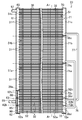
- FIG. 2 is a front view illustrating a schematic configuration of the outdoor heat exchanger according to the first embodiment.
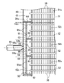
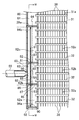
- FIG. 3 is a partial cross-sectional view illustrating the front of the outdoor heat exchanger according to the first embodiment.
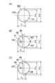
- FIG. 4 is a cross-sectional view of the outdoor heat exchanger showing a part of the AA cross section of FIG. 3 in an enlarged manner.
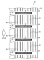
- FIG. 5 is an enlarged cross-sectional view illustrating the front of the main part of the outdoor heat exchanger according to the first embodiment.
- FIG. 6 is an enlarged cross-sectional view showing a main part of the outdoor heat exchanger of Embodiment 1, wherein (A) shows a part of the BB cross section of FIG. 5, and (B) shows (A).
- FIG. 4C shows a cross section taken along the line CC
- FIG. 3C shows a cross section taken along the line DD in FIG.
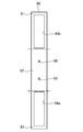
- FIG. 7 is a plan view of a vertical partition plate provided in the outdoor heat exchanger of the first embodiment.
- FIG. 8 is a cross-sectional view showing, in an enlarged manner, the front of the main part of the outdoor heat exchanger according to a modification of the first embodiment (when there are four communication chambers).
- FIG. 9 is an enlarged cross-sectional view of the main part of the outdoor heat exchanger according to the modification of the first embodiment (when there are five communication chambers).
- FIG. 10 is an enlarged cross-sectional view showing the front of the main part of the outdoor heat exchanger according to the second embodiment.
- FIG. 11 is an enlarged cross-sectional view showing a main part of the outdoor heat exchanger according to the second embodiment, in which (A) shows a part of the EE cross section of FIG. 10, and (B) shows (A) FIG. 2C shows a FF cross section of FIG. 1, and
- FIG. FIG. 12 is an enlarged cross-sectional view illustrating the front of the main part of the outdoor heat exchanger according to the third embodiment.
- FIG. 10 is an enlarged cross-sectional view showing the front of the main part of the outdoor heat exchanger according to the second embodiment.
- FIG. 11 is an enlarged cross-sectional view showing a main part of the outdoor heat exchanger according to the second embodiment, in which (A) shows a
- FIG. 13 is an enlarged cross-sectional view illustrating a main part of the outdoor heat exchanger according to the third embodiment, in which (A) shows a part of the HH cross section of FIG. 12, and (B) shows (A) II shows a cross section taken along II, and (C) shows a JJ cross section of (A).
- FIG. 14 is an enlarged cross-sectional view illustrating the front of the main part of the outdoor heat exchanger according to the fourth embodiment.
- FIG. 15 is an enlarged cross-sectional view illustrating the front of the main part of the outdoor heat exchanger according to the fifth embodiment.
- 16 is an enlarged cross-sectional view showing the main part of the outdoor heat exchanger according to the fifth embodiment.
- FIG. 16A is a cross-sectional view taken along the line KK in FIG.
- FIG. 17 is a partial cross-sectional view illustrating the front of the outdoor heat exchanger according to the sixth embodiment.
- FIG. 18 is an enlarged cross-sectional view illustrating the front of the main part of the outdoor heat exchanger according to the sixth embodiment.
- FIG. 19 is an enlarged cross-sectional view illustrating a main part of the outdoor heat exchanger according to the sixth embodiment, in which (A) shows a part of the MM cross section of FIG. 18, and (B) shows (A) The NN cross section of (A) is shown, (C) shows the OO cross section of (A).
- FIG. 20 is a plan view of a vertical partition provided in the outdoor heat exchanger of the sixth embodiment.
- FIG. 20 is a plan view of a vertical partition provided in the outdoor heat exchanger of the sixth embodiment.
- FIG. 21 is a partial cross-sectional view illustrating the front of an outdoor heat exchanger according to a modification of the sixth embodiment.
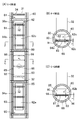
- FIG. 22 is an enlarged front view showing a main part of the outdoor heat exchanger according to the seventh embodiment during assembly.
- FIG. 23 is a plan view of a partition plate provided in the outdoor heat exchanger of Embodiment 7, wherein (A) shows the partition plate of the first header collecting pipe, and (B) shows the upper horizontal partition plate. , (C) shows the lower horizontal partition plate.
- FIG. 24 is an enlarged cross-sectional view showing a main part of the outdoor heat exchanger according to the seventh embodiment, in which (A) shows a part of the PP cross section of FIG. 22, and (B) shows (A).
- FIG. 25 is a cross-sectional view of the first header collecting pipe of the outdoor heat exchanger of Embodiment 7, wherein (A) shows a state in which the lower horizontal partition plate is mistakenly fitted into the upper insertion hole, B) shows a state in which the upper horizontal partition plate is erroneously fitted into the lower insertion hole.
- Embodiment 1 of the Invention A first embodiment of the present invention will be described.
- the heat exchanger of this embodiment is an outdoor heat exchanger (23) provided in the air conditioner (10).
- an air conditioner (10) is demonstrated first, and the outdoor heat exchanger (23) is demonstrated in detail after that.
- the air conditioner (10) includes an outdoor unit (11) and an indoor unit (12).
- the outdoor unit (11) and the indoor unit (12) are connected to each other via a liquid side connecting pipe (13) and a gas side connecting pipe (14).
- a refrigerant circuit (20) is formed by the outdoor unit (11), the indoor unit (12), the liquid side communication pipe (13), and the gas side communication pipe (14).
- the refrigerant circuit (20) is provided with a compressor (21), a four-way switching valve (22), an outdoor heat exchanger (23), an expansion valve (24), and an indoor heat exchanger (25). ing.
- the compressor (21), the four-way switching valve (22), the outdoor heat exchanger (23), and the expansion valve (24) are accommodated in the outdoor unit (11).
- the outdoor unit (11) is provided with an outdoor fan (15) for supplying outdoor air to the outdoor heat exchanger (23).
- the indoor heat exchanger (25) is accommodated in the indoor unit (12).
- the indoor unit (12) is provided with an indoor fan (16) for supplying room air to the indoor heat exchanger (25).
- the refrigerant circuit (20) is a closed circuit filled with refrigerant.
- the compressor (21) has a discharge pipe connected to the first port of the four-way switching valve (22) and a suction pipe connected to the second port of the four-way switching valve (22).
- the outdoor heat exchanger (23), the expansion valve (24), and the indoor heat exchanger are sequentially arranged from the third port to the fourth port of the four-way switching valve (22). (25) and are arranged.
- Compressor (21) is a scroll type or rotary type hermetic compressor.
- the four-way switching valve (22) includes a first state (state indicated by a solid line in FIG. 1) in which the first port communicates with the third port and the second port communicates with the fourth port; The port is switched to a second state (state indicated by a broken line in FIG. 1) in which the port communicates with the fourth port and the second port communicates with the third port.
- the expansion valve (24) is a so-called electronic expansion valve.
- the outdoor heat exchanger (23) exchanges heat between the outdoor air and the refrigerant.
- the outdoor heat exchanger (23) will be described later.
- the indoor heat exchanger (25) exchanges heat between the indoor air and the refrigerant.
- the indoor heat exchanger (25) is constituted by a so-called cross fin type fin-and-tube heat exchanger provided with a heat transfer tube which is a circular tube.
- the air conditioner (10) selectively performs a cooling operation and a heating operation.
- the refrigeration cycle is performed with the four-way switching valve (22) set to the first state.
- the refrigerant circulates in the order of the outdoor heat exchanger (23), the expansion valve (24), and the indoor heat exchanger (25), and the outdoor heat exchanger (23) functions as a condenser.
- the outdoor heat exchanger (23) functions as a condenser.
- the outdoor heat exchanger (23) functions as an evaporator.
- the gas refrigerant flowing from the compressor (21) dissipates heat to the outdoor air and condenses, and the condensed refrigerant flows out toward the expansion valve (24).
- the refrigeration cycle is performed with the four-way switching valve (22) set to the second state.
- the refrigerant circulates in the order of the indoor heat exchanger (25), the expansion valve (24), and the outdoor heat exchanger (23), and the indoor heat exchanger (25) functions as a condenser.
- the indoor heat exchanger (25) functions as a condenser.
- (23) functions as an evaporator.
- the refrigerant that has expanded into the gas-liquid two-phase state flows into the outdoor heat exchanger (23) when passing through the expansion valve (24).
- the refrigerant that has flowed into the outdoor heat exchanger (23) absorbs heat from the outdoor air and evaporates, and then flows out toward the compressor (21).
- the outdoor heat exchanger (23) includes one first header collecting pipe (60), one second header collecting pipe (70), and many flat tubes (31, 31). 32) and a large number of fins (36).
- the first header collecting pipe (60), the second header collecting pipe (70), the flat pipe (31, 32) and the fin (35) are all made of an aluminum alloy and are joined to each other by brazing. Yes.
- the outdoor heat exchanger (23) is divided into a main heat exchange region (51) and an auxiliary heat exchange region (52).
- some flat tubes (32) constitute an auxiliary heat exchange region (52)
- the remaining flat tubes (31) constitute a main heat exchange region (51). .
- the first header collecting pipe (60) and the second header collecting pipe (70) are both formed in an elongated cylindrical shape whose both ends are closed. 2 and 3, the first header collecting pipe (60) stood up at the left end of the outdoor heat exchanger (23), and the second header collecting pipe (70) stood up at the right end of the outdoor heat exchanger (23). It is installed in a state. That is, the first header collecting pipe (60) and the second header collecting pipe (70) are installed in a state where the respective axial directions are in the vertical direction.
- the flat tubes (31, 32) are heat transfer tubes whose cross-sectional shape is a flat oval.
- the plurality of flat tubes (31, 32) are arranged in a state in which the extending direction is the left-right direction and the flat side surfaces face each other.
- the plurality of flat tubes (31, 32) are arranged side by side at regular intervals and are substantially parallel to each other.
- Each flat tube (31, 32) has one end inserted into the first header collecting tube (60) and the other end inserted into the second header collecting tube (70).
- each fluid passage (34) is a passage extending in the extending direction of the flat tube (31, 32).
- the plurality of fluid passages (34) are arranged in a line in the width direction of the flat tube (31, 32) (that is, the direction orthogonal to the longitudinal direction).
- One end of each of the plurality of fluid passages (34) formed in each flat tube (31, 32) communicates with the internal space of the first header collecting pipe (60), and the other end of each fluid passage (34) is the second header collecting pipe. It communicates with the internal space of (70).
- the refrigerant supplied to the outdoor heat exchanger (23) exchanges heat with air while flowing through the fluid passage (34) of the flat tubes (31, 32).
- the fin (36) is a vertically long plate-like fin formed by pressing a metal plate.
- the fin (36) is formed with a number of elongated notches (45) extending in the width direction of the fin (36) from the front edge of the fin (36) (that is, the windward edge).
- a large number of notches (45) are formed at regular intervals in the longitudinal direction (vertical direction) of the fin (36).
- the portion closer to the lee of the notch (45) constitutes the tube insertion portion (46).
- the tube insertion portion (46) has a vertical width substantially equal to the thickness of the flat tube (31, 32) and a length substantially equal to the width of the flat tube (31, 32).
- the flat tubes (31, 32) are inserted into the tube insertion portion (46) of the fin (36) and joined to the peripheral portion of the tube insertion portion (46) by brazing. Moreover, the louver (40) for promoting heat transfer is formed in the fin (36).
- the plurality of fins (36) are arranged in the extending direction of the flat tubes (31, 32) so that the air flows between the adjacent flat tubes (31, 32) into the plurality of ventilation paths (38). It is partitioned.
- the outdoor heat exchanger (23) is divided into two heat exchange regions (51, 52) in the vertical direction.
- the upper heat exchange region is the main heat exchange region (51)
- the lower heat exchange region is the auxiliary heat exchange region (52).
- Each heat exchange area (51, 52) is divided into three heat exchange sections (51a to 51c, 52a to 52c). That is, in the outdoor heat exchanger (23), each of the main heat exchange region (51) and the auxiliary heat exchange region (52) is divided into a plurality of heat exchange portions (51a to 51c, 52a to 52c). ing.
- the number of heat exchanging portions (51a to 51c, 52a to 52c) formed in each heat exchanging region (51, 52) may be two, or four or more.
- the first main heat exchange unit (51a), the second main heat exchange unit (51b), and the third main heat exchange unit are sequentially arranged from the bottom to the top. (51c) is formed.
- a first auxiliary heat exchange unit (52a), a second auxiliary heat exchange unit (52b), and a third auxiliary heat exchange unit (52c) Is formed.
- Each main heat exchange section (51a to 51c) and each auxiliary heat exchange section (52a to 52c) are provided with a plurality of flat tubes (31, 32). Further, as shown in FIG.
- the number of flat tubes (31) constituting each main heat exchange section (51a to 51c) is equal to the number of flat tubes (32) constituting each auxiliary heat exchange section (52a to 52c). More than the number. Therefore, the number of flat tubes (31) constituting the main heat exchange region (51) is larger than the number of flat tubes (32) constituting the auxiliary heat exchange region (52). In the outdoor heat exchanger (23) of the present embodiment, the number of flat tubes (32) constituting each auxiliary heat exchange section (52a to 52c) is three.
- the internal space of the first header collecting pipe (60) is vertically divided by a partition plate (39a).
- the space above the partition plate (39a) is the upper space (61), and the space below the partition plate (39a) is the lower space (62).
- the upper space (61) constitutes a main communication space corresponding to the main heat exchange area (51).
- the upper space (61) is a single space communicating with all of the flat tubes (31) constituting the main heat exchange region (51). That is, the upper space (61) communicates with the flat tube (31) of each main heat exchange section (51a to 51c).
- the lower space (62) constitutes an auxiliary communication space corresponding to the auxiliary heat exchange region (52). Although details will be described later, the lower space (62) is partitioned into the same number (three in the present embodiment) of communication chambers (62a to 62c) as the auxiliary heat exchange sections (52a to 52c).
- the lowermost first communication chamber (62a) communicates with all the flat tubes (32) constituting the first auxiliary heat exchange section (52a).
- the second communication chamber (62b) located above the first communication chamber (62a) communicates with all the flat tubes (32) constituting the second auxiliary heat exchange section (52b).
- the uppermost third communication chamber (62c) communicates with all the flat tubes (32) constituting the third auxiliary heat exchange section (52c).
- the internal space of the second header collecting pipe (70) is divided into a main communication space (71) corresponding to the main heat exchange area (51) and an auxiliary communication space (72) corresponding to the auxiliary heat exchange area (52). Has been.
- the main communication space (71) is divided up and down by two partition plates (39c).
- the partition plate (39c) divides the main communication space (71) into the same number (three in this embodiment) of partial spaces (71a to 71c) as the main heat exchange portions (51a to 51c).
- the lowermost first partial space (71a) communicates with all the flat tubes (31) constituting the first main heat exchange section (51a).
- the second partial space (71b) located above the first partial space (71a) communicates with all the flat tubes (31) constituting the second main heat exchange section (51b).
- the uppermost third partial space (71c) communicates with all the flat tubes (31) constituting the third main heat exchange section (51c).
- the auxiliary communication space (72) is vertically divided by two partition plates (39d).
- the partition plate (39d) divides the auxiliary communication space (72) into the same number (three in this embodiment) of partial spaces (72a to 72c) as the auxiliary heat exchange parts (52a to 52c).
- the lowermost fourth partial space (72a) communicates with all the flat tubes (32) constituting the first auxiliary heat exchange section (52a).
- the fifth partial space (72b) located above the fourth partial space (72a) communicates with all the flat tubes (32) constituting the second auxiliary heat exchange section (52b).
- the sixth partial space (72c) located at the uppermost position communicates with all the flat tubes (32) constituting the third auxiliary heat exchange section (52c).
- connection pipes (76, 77) are attached to the second header collecting pipe (70). These connection pipes (76, 77) are all circular pipes.
- the first connection pipe (76) has one end connected to the second partial space (71b) corresponding to the second main heat exchange part (51b) and the other end corresponding to the first auxiliary heat exchange part (52a). Connected to the fourth partial space (72a).
- the second connection pipe (77) has one end connected to the third partial space (71c) corresponding to the third main heat exchange part (51c) and the other end corresponding to the second auxiliary heat exchange part (52b). Connected to the fifth partial space (72b).
- a sixth partial space (72c) corresponding to the third auxiliary heat exchange section (52c) and a first partial space corresponding to the first main heat exchange section (51a) ( 71a) form one continuous space.
- the 1st main heat exchange part (51a) and the 3rd auxiliary heat exchange part (52c) are connected in series, and the 2nd main heat exchange part (51b ) And the first auxiliary heat exchanger (52a) are connected in series, and the third main heat exchanger (51c) and the second auxiliary heat exchanger (52b) are connected in series.
- the outdoor heat exchanger (23) is provided with a liquid side connection pipe (55) and a gas side connection pipe (57).
- the liquid side connecting pipe (55) and the gas side connecting pipe (57) are aluminum alloy members formed in a circular tube shape.
- the liquid side connection pipe (55) and the gas side connection pipe (57) are joined to the first header collecting pipe (60) by brazing.
- liquid side connection pipe (55) which is a tubular member, is connected to the lower part of the first header collecting pipe (60) and communicates with the lower space (62).
- the other end of the liquid side connection pipe (55) is connected to a copper pipe (17) connecting the outdoor heat exchanger (23) and the expansion valve (24) via a joint (not shown).
- One end of the gas side connection pipe (57) is connected to the upper part of the first header collecting pipe (60) and communicates with the upper space (61).
- the other end of the gas side connection pipe (57) is connected to a copper pipe (18) connecting the outdoor heat exchanger (23) and the third port of the four-way switching valve (22) via a joint (not shown). It is connected.
- an upper horizontal partition plate (80), a lower horizontal partition plate (85), and a vertical partition plate (90) are installed one by one. (See FIG. 5).
- the lower space (62) is divided into three communication chambers (62a to 62c) and one mixing chamber (63) by the horizontal partition plates (80, 85) and the vertical partition plate (90). Yes.
- the material of the upper horizontal partition plate (80), the lower horizontal partition plate (85), and the vertical partition plate (90) is an aluminum alloy.
- Each of the upper lateral partition plate (80) and the lower lateral partition plate (85) is formed in a disc shape and partitions the lower space (62) vertically.
- the upper horizontal partition plate (80) and the lower horizontal partition plate (85) are joined to the first header collecting pipe (60) by brazing.
- the upper horizontal partition plate (80) is disposed at the boundary between the second auxiliary heat exchange part (52b) and the third auxiliary heat exchange part (52c), and connects the second communication chamber (62b) and the third communication chamber (62c). Partitioning.
- the lower horizontal partition plate (85) is disposed at the boundary between the first auxiliary heat exchange section (52a) and the second auxiliary heat exchange section (52b), and is connected to the first communication chamber (62a) and the second communication chamber (62b). Partitioning.
- Each of the upper lateral partition plate (80) and the lower lateral partition plate (85) is formed with one slit hole (82, 87) and one through hole for communication (81, 86) (FIG. 5). And FIG. 6).
- the slit holes (82, 87) are elongated rectangular holes, and penetrate the horizontal partition plates (80, 85) in the thickness direction.
- the long sides of the slit holes (82, 87) are substantially parallel to the end face of the flat tube (32).
- the slit hole (82, 87) is located closer to the back surface of the first header collecting pipe (60).
- the width of the slit holes (82, 87) is substantially the same as the thickness of the vertical partition plate (90), and the length thereof is substantially the same as the width of the vertical partition plate (90).
- the communication through holes (81, 86) are circular holes and penetrate the horizontal partition plates (80, 85) in the thickness direction. In each horizontal partition plate (80, 85), the communication through holes (81, 86) are located closer to the back surface of the first header collecting pipe (60) than the slit holes (82, 87). In addition, the diameters of the through holes (81, 86) for communication of the upper horizontal partition plate (80) and the lower horizontal partition plate (85) are equal to each other.
- the vertical partition plate (90) is formed in a vertically long rectangular plate shape (see FIG. 7).
- the vertical partition plate (90) is inserted through the slit hole (82) of the upper horizontal partition plate (80) and the slit hole (87) of the lower horizontal partition plate (85) (see FIGS. 5 and 6). reference).
- the vertical partition plate (90) faces the end surface of the flat tube (32) inserted into the first header collecting tube (60).
- the lower end of the vertical partition plate (90) is in contact with the bottom of the first header collecting pipe (60), and the upper end is in contact with the partition plate (39a).
- the vertical partition plate (90) is in contact with the inner peripheral surface of the first header collecting pipe (60) at both sides in the width direction (left and right direction in FIG. 6).
- the vertical partition plate (90) is not joined to other members.
- the vertical partition plate (90) is inserted into the slit hole (82, 87) of each horizontal partition plate (80, 85) and abuts on the partition plate (39a) and the bottom of the first header collecting pipe (60). This holds the posture.
- the upper portion of the upper horizontal partition plate (80) is the upper portion (91), and the portion between the upper horizontal partition plate (80) and the lower horizontal partition plate (85) is intermediate.
- a portion (92) is formed, and a portion below the lower horizontal partition plate (85) is a lower portion (93) (see FIGS. 5 and 6).
- the middle part (92) of the vertical partition (90) is located in the space between the upper horizontal partition (80) and the lower horizontal partition (85) on the front side of the first header collecting pipe (60). It is partitioned into a second communication chamber (62b) and a mixing chamber (63) located on the back side thereof. That is, in the first header collecting pipe (60), the mixing chamber (63) is formed on the back side of the second communication chamber (62b).
- the mixing chamber (63) includes an intermediate portion (92) of the vertical partition plate (90), an upper horizontal partition plate (80), a lower horizontal partition plate (85), and a first header collecting pipe (60). It is surrounded by the side wall.
- the vertical partition plate (90) has two rectangular openings (94a, 94b) and two circular communication through holes (95, 95). Each opening (94a, 94b) and each communicating through hole (95, 95) penetrate the vertical partition plate (90) in the thickness direction.
- One opening (94a, 94b) is formed in each of the upper part (91) and the lower part (93) of the vertical partition plate (90).
- the upper opening (94b) occupies most of the upper part (91) of the vertical partition (90). Accordingly, in the third communication chamber (62c) located on the upper side of the upper horizontal partition plate (80), the portions on both sides of the vertical partition plate (90) are substantially one space.
- the lower opening (94a) occupies most of the lower part (93) of the vertical partition (90). Therefore, in the first communication chamber (62a) located on the lower side of the lower horizontal partition plate (85), both side portions of the vertical partition plate (90) are substantially one space.
- the communication through hole (95) is formed in an intermediate portion (92) of the vertical partition plate (90).
- the communication through hole (95) is a circular hole having a diameter of about 2 mm, and is arranged one above and below the center in the vertical direction of the intermediate portion (92).
- the vertical partition plate (90) has one opening (94a, 94b) at each end in the longitudinal direction, and two communication through holes between the openings (94a, 94b). (95, 95) is formed.
- the two openings (94a, 94b) and the two communication through holes (95, 95) are arranged in a line in the longitudinal direction of the vertical partition plate (90).
- the shape of the vertical partition (90) is vertically symmetric and symmetric.
- the vertical partition plate (90) has a communication through hole (95), the upper horizontal partition plate (80) has a communication through hole (81), and the lower horizontal partition plate (85) has a communication through hole.
- a communication through hole (86) is formed.
- the communication through hole (95) of the vertical partition (90) allows the mixing chamber (63) to communicate with the second communication chamber (62b).
- the communication through hole (95) of the upper horizontal partition (80) allows the mixing chamber (63) to communicate with the third communication chamber (62c).
- the communication through hole (86) of the lower horizontal partition (85) allows the mixing chamber (63) to communicate with the first communication chamber (62a).
- These communication through holes (81, 86, 95) constitute a distribution passage (65) for distributing the refrigerant in the mixing chamber (63) to the communication chambers (62a to 62c).
- a connection port (66) for inserting the liquid side connection pipe (55) is formed in the side wall portion of the first header collecting pipe (60).
- the connection port (66) is a circular through hole.
- the connection port (66) is formed in a portion of the first header collecting pipe (60) between the upper horizontal partition plate (80) and the lower horizontal partition plate (85), and communicates with the mixing chamber (63). Yes.
- the center of the connection port (66) is located at the center in the height direction of the mixing chamber (63). Accordingly, as shown in FIG.
- connection port (66) faces a portion between the two communication through holes (95) in the vertical partition plate (90).
- the liquid side connection pipe (55) has a shape in which the connection end (56) inserted into the connection port (66) of the first header collecting pipe (60) is narrowed. That is, in the liquid side connection pipe (55), the inner diameter d of the connection end (56) is smaller than the inner diameter of the other part. Further, the outer diameter of the connection end (56) is substantially equal to the diameter of the connection port (66). In the present embodiment, the diameters of the communication through holes (81, 86) of the upper side partition plate (80) and the lower side partition plate (85) are the inner diameters of the connection end portions (56) of the liquid side connection pipe (55).
- the area of the communication through hole (81) of the upper horizontal partition plate (80) and the area of the communication through hole (86) of the lower horizontal partition plate (85) are the same as those of the vertical partition plate (90). It is equal to the total area of the two through holes (95) for communication.
- the gas refrigerant discharged from the compressor (21) is supplied to the outdoor heat exchanger (23).
- the gas refrigerant sent from the compressor (21) flows into the upper space (61) of the first header collecting pipe (60) via the gas side connection pipe (57), and then flows into the main heat exchange region (51). It is distributed to each flat tube (31).
- the refrigerant flowing into the fluid passage (34) of the flat tube (31) dissipates heat to the outdoor air while flowing through the fluid passage (34). Then, it condenses and then flows into the corresponding partial spaces (71a to 71c) of the second header collecting pipe (70).
- the refrigerant that has flowed into the partial spaces (71a to 71c) of the main communication space (71) is sent to the corresponding partial spaces (72a to 72c) of the auxiliary communication space (72).
- the refrigerant flowing into the first partial space (71a) of the main communication space (71) flows down and flows into the sixth partial space (72c) of the auxiliary communication space (72).
- the refrigerant flowing into the second partial space (71b) of the main communication space (71) flows into the fourth partial space (72a) of the auxiliary communication space (72) through the first connection pipe (76).
- the refrigerant that has flowed into the third partial space (71c) of the main communication space (71) flows into the fifth partial space (72b) of the auxiliary communication space (72) through the second connection pipe (77).
- the refrigerant that has flowed into the partial spaces (72a to 72c) of the auxiliary communication space (72) is distributed to the flat tubes (32) of the corresponding auxiliary heat exchange sections (52a to 52c).
- the refrigerant flowing through the fluid passage (34) of each flat tube (32) dissipates heat to the outdoor air and becomes supercooled liquid, and then the corresponding communication chamber in the lower space (62) of the first header collecting pipe (60). Flows into (62a-62c). Thereafter, the refrigerant flows into the liquid side connecting pipe (55) through the mixing chamber (63) and flows out of the outdoor heat exchanger (23).
- the outdoor heat exchanger (23) is supplied with a refrigerant that has expanded into a gas-liquid two-phase state when passing through the expansion valve (24).
- the gas-liquid two-phase refrigerant flowing from the expansion valve (24) passes through the liquid side connection pipe (55) inserted into the connection port (66), and is mixed in the mixing chamber (60) in the first header collecting pipe (60). 63).
- the refrigerant passes through the connection end (56) of the liquid side connection pipe (55)
- the flow rate rises, and the high flow rate refrigerant ejected from the liquid side connection pipe (55) becomes the vertical partition plate (90 ).
- the mixing chamber (63) the refrigerant is vigorously disturbed, and the gas refrigerant and liquid refrigerant in the refrigerant are mixed. That is, the refrigerant in the mixing chamber (63) is homogenized, and the wetness of the refrigerant in the mixing chamber (63) becomes substantially uniform.
- the refrigerant in the mixing chamber (63) is distributed to each communication chamber (62a to 62c). That is, the refrigerant in the mixing chamber (63) flows into the first communication chamber (62a) through the communication through hole (86) of the lower horizontal partition plate (85), and communicates with the vertical partition plate (90). It flows into the second communication chamber (62b) through the communication through hole (95), and flows into the third communication chamber (62c) through the communication through hole (81) of the upper lateral partition plate (80).
- the gas-liquid two-phase refrigerant in the mixing chamber (63) is homogenized. For this reason, the wetness of the refrigerant flowing into the communication chambers (62a to 62c) from the mixing chamber (63) is substantially the same.
- the area of the communication through hole (81) of the upper horizontal partition plate (80) and the area of the communication through hole (86) of the lower horizontal partition plate (85) It is equal to the sum of the areas of the two through holes (95) for (90). For this reason, the mass flow rate of the refrigerant flowing from the mixing chamber (63) into the communication chambers (62a to 62c) is also substantially the same.
- the refrigerant that has flowed into the communication chambers (62a to 62c) of the first header collecting pipe (60) is distributed to the flat tubes (32) of the corresponding auxiliary heat exchange sections (52a to 52c).
- the refrigerant flowing into the fluid passage (34) of each flat tube (32) absorbs heat from the outdoor air while flowing through the fluid passage (34), and a part of the liquid refrigerant evaporates.
- the refrigerant that has passed through the fluid passage (34) of the flat tube (32) flows into the corresponding partial spaces (72a to 72c) of the auxiliary communication space (72) of the second header collecting pipe (70).
- the refrigerant that has flowed into the partial spaces (72a to 72c) still remains in a gas-liquid two-phase state.
- the refrigerant that has flowed into the partial spaces (72a to 72c) of the auxiliary communication space (72) is sent to the corresponding partial spaces (71a to 71c) of the main communication space (71).
- the refrigerant flowing into the fourth partial space (72a) of the auxiliary communication space (72) passes through the first connection pipe (76) to the second partial space (71b) of the main communication space (71). Inflow.
- the refrigerant that has flowed into the fifth partial space (72b) of the auxiliary communication space (72) flows into the third partial space (71c) of the main communication space (71) through the second connection pipe (77).
- the refrigerant flowing into the sixth partial space (72c) of the auxiliary communication space (72) flows upward and flows into the first partial space (71a) of the main communication space (71).
- the refrigerant that has flowed into the partial spaces (71a to 71c) of the main communication space (71) is distributed to the flat tubes (31) of the corresponding main heat exchange sections (51a to 51c).
- the refrigerant flowing through the fluid passageway (34) of each flat tube (31) absorbs heat from the outdoor air and evaporates to substantially become a gas single-phase state, and then the upper space of the first header collecting pipe (60) ( 61). Thereafter, the refrigerant flows out of the outdoor heat exchanger (23) through the gas side connection pipe (57).
- the gas-liquid two-phase refrigerant passes through the liquid side connection pipe (55) and is mixed in the mixing chamber (63 in the first header collecting pipe (60)). ). At that time, the high-flow-rate refrigerant ejected from the liquid side connecting pipe (55) collides with the vertical partition plate (90), and the refrigerant in the mixing chamber (63) is vigorously disturbed.
- the homogenized gas-liquid two-phase refrigerant in the mixing chamber (63) is distributed to the three communication chambers (62a to 62c), and then communicated with each other. It flows into three flat tubes (32) communicating with the chambers (62a-62c). For this reason, the wetness of the gas-liquid two-phase refrigerant flowing into the plurality of communication chambers (62a to 62c) is made uniform, and as a result, flows from the communication chamber (62a to 62c) into each flat tube (32). The wetness of the refrigerant is also made uniform.
- the wetness and mass flow rate of the refrigerant flowing into the communication chambers (62a to 62c) can be made uniform. it can.
- the wetness and mass flow rate of the refrigerant flowing into each flat tube (32) communicating with the communication chamber (62a-62c) can be made uniform, and the performance of the outdoor heat exchanger (23) can be fully demonstrated. Can be made.
- the gas-liquid two-phase refrigerant supplied to the outdoor heat exchanger (23) functioning as an evaporator is homogenized in the mixing chamber (63), and then a plurality of vertically aligned refrigerants. It is distributed to the communication room (62a-62c). Therefore, according to the present embodiment, refrigerant having substantially the same wetness is supplied from the mixing chamber (63) to the plurality of communication chambers (62a to 62c) arranged in the vertical direction while suppressing the influence of gravity acting on the refrigerant. be able to.
- connection port (66) of the first header collecting pipe (60) faces the vertical partition plate (90), and further, the vertical partition plate (90) Is disposed closer to the connection port (66) than the central axis (64) of the first header collecting pipe (60). Therefore, according to the present embodiment, the flow rate of the refrigerant that is ejected from the liquid side connection pipe (55) and collides with the vertical partition plate (90) can be increased, and the refrigerant in the mixing chamber (63) is further scraped. It can be disturbed to promote homogenization of the refrigerant.
- the mixing chamber (63) in the first header collecting pipe (60) is connected to the first communication chamber (62a) with the lower horizontal partition plate (85) interposed therebetween.
- the through holes (81, 86) for communication are formed in the horizontal partition plates (80, 85) and the communication through holes (95) are formed in the vertical partition plate (90).
- the distribution passage (65) can be configured by the communication through holes (81, 86, 95) having a simple structure, and the structure of the outdoor heat exchanger (23) can be complicated. Can be suppressed.
- the number of communication chambers formed in the first header collecting pipe (60) of the outdoor heat exchanger (23) is not limited to three.
- the structure of the lower part of the first header collecting pipe (60) will be described for each of the cases where the number of communication rooms is four and five.
- differences from the structure of the first header collecting pipe (60) in the case where the number of communication chambers (62a to 62c) shown in FIG. 5 is three will be described.
- the auxiliary heat exchange region (52) of the outdoor heat exchanger (23) is divided into the same number (that is, four) of auxiliary heat exchange sections (52a to 52d) as the communication chambers (62a to 62d).
- the first auxiliary heat exchange unit (52a), the second auxiliary heat exchange unit (52b), and the third auxiliary heat exchange unit (52c) The fourth auxiliary heat exchange part (52d) is arranged.
- the main heat exchange area (51) of the outdoor heat exchanger (23) has the same number (that is, four) of main heat exchange sections as the auxiliary heat exchange sections (52a to 52d). It is divided into.
- the lower space (62) of the first header collecting pipe (60) there are an upper horizontal partition plate (80), a lower horizontal partition plate (85), and an intermediate horizontal partition plate (89). ) And one vertical partition plate (90).
- the lower space (62) is divided into four communication chambers (62a to 62d) and one mixing chamber (63) by these horizontal partition plates (80, 85, 89) and vertical partition plates (90).
- the first communication chamber (62a), the second communication chamber (62b), the third communication chamber (62c), and the fourth communication chamber (62d) are sequentially arranged from the bottom to the top.
- the material of the intermediate horizontal partition plate (89) is an aluminum alloy.
- the upper horizontal partition plate (80) is disposed at the boundary between the third auxiliary heat exchange section (52c) and the fourth auxiliary heat exchange section (52d), and connects the third communication chamber (62c) and the fourth communication chamber (62d). Partitioning.
- the intermediate horizontal partition plate (89) is disposed at the boundary between the second auxiliary heat exchange section (52b) and the third auxiliary heat exchange section (52c), and connects the second communication chamber (62b) and the third communication chamber (62c). Partitioning.
- the intermediate horizontal partition plate (89) partitions the space on the flat tube (32) side up and down from the vertical partition plate (90).
- the lower horizontal partition plate (85) is disposed at the boundary between the first auxiliary heat exchange section (52a) and the second auxiliary heat exchange section (52b), and is connected to the first communication chamber (62a) and the second communication chamber (62b). Partitioning.
- the length of the intermediate portion (92) is longer than that of the vertical partition plate (90) shown in FIG.
- An intermediate portion (92) of the vertical partition plate (90) is located on the back side of the second communication chamber (62b) and the third communication chamber (62c) (that is, the side opposite to the flat tube (32)), The second communication chamber (62b) and the third communication chamber (62c) are separated from the mixing chamber (63).
- the mixing chamber (63) shown in FIG. 8 is similar to the mixing chamber (63) shown in FIG. 5 in that the middle portion (92) of the vertical partition plate (90), the upper horizontal partition plate (80), and the lower side It is surrounded by the partition plate (85) and the side wall portion of the first header collecting pipe (60).
- the two lower communication through holes (95a) are formed in the vertical partition plate (90) adjacent to the second communication chamber (62b), and the second communication chamber (62b) serves as the mixing chamber (63). Communicate with.
- the upper two through holes (95b) for communication are formed in a portion of the vertical partition plate (90) adjacent to the third communication chamber (62c), and the third communication chamber (62c) is connected to the mixing chamber (63). Communicate.
- These communication through holes (95a, 95b) constitute a distribution passage (65) together with the communication through holes (81, 86) of the upper lateral partition plate (80) and the lower lateral partition plate (85).
- the diameters of the communication through holes (95a, 95b) formed in the vertical partition plate (90) are equal to each other. In addition, the diameters of these communication through holes (95a, 95b) are smaller than the diameters of the communication through holes (81, 86) formed in the upper lateral partition plate (80) and the lower lateral partition plate (85). .
- the upper part (91) of the vertical partition (90) shown in FIG. 8 is located in the fourth communication chamber (62d) formed on the upper side of the upper horizontal partition (80). Similar to the vertical partition plate (90) shown in FIG. 5, the opening (94b) formed near the upper end of the vertical partition plate (90) occupies most of the upper portion (91) of the vertical partition plate (90). ing. Accordingly, in the fourth communication chamber (62d), the portions on both sides of the vertical partition plate (90) are substantially one space.
- connection port (66) shown in FIG. 8 is located at the center in the height direction of the mixing chamber (63).
- the connection end (56) of the liquid side connection pipe (55) is inserted into the connection port (66).
- the connection end (56) has a constricted shape.
- the gas-liquid two-phase refrigerant flows into the mixing chamber (63) from the liquid side connection pipe (55), and the liquid side connection pipe ( The refrigerant ejected from 55) collides with the vertical partition plate (90).
- the refrigerant in the mixing chamber (63) is distributed to the four communication chambers (62a to 62d). That is, the refrigerant in the mixing chamber (63) flows into the first communication chamber (62a) through the communication through hole (86) of the lower horizontal partition plate (85), and flows under the vertical partition plate (90).
- the auxiliary heat exchange region (52) of the outdoor heat exchanger (23) is divided into the same number (that is, five) of auxiliary heat exchange sections (52a to 52e) as the communication chambers (62a to 62e).
- the first auxiliary heat exchange unit (52a), the second auxiliary heat exchange unit (52b), and the third auxiliary heat exchange unit (52c) The fourth auxiliary heat exchange unit (52d) and the fifth auxiliary heat exchange unit (52e) are arranged.
- the main heat exchange area (51) of the outdoor heat exchanger (23) has the same number (ie, five) main heat exchange sections as the auxiliary heat exchange sections (52a to 52e). It is divided into.
- each intermediate horizontal partition plate (89a, 89b) is an aluminum alloy.
- the upper horizontal partition plate (80) is disposed at the boundary between the fourth auxiliary heat exchange section (52d) and the fifth auxiliary heat exchange section (52e), and connects the fourth communication chamber (62d) and the fifth communication chamber (62e). Partitioning.
- the upper intermediate horizontal partition plate (89b) is disposed at the boundary between the third auxiliary heat exchanging portion (52c) and the fourth auxiliary heat exchanging portion (52d), and is connected to the third communication chamber (62c) and the fourth communication chamber (62d).
- the lower intermediate horizontal partition plate (89a) is disposed at the boundary between the second auxiliary heat exchanging portion (52b) and the third auxiliary heat exchanging portion (52c), and the second communicating chamber (62b) and the third communicating chamber ( 62c).
- the intermediate horizontal partition plates (89a, 89b) partition the space on the flat tube (32) side up and down from the vertical partition plate (90).
- the lower horizontal partition plate (85) is disposed at the boundary between the first auxiliary heat exchange section (52a) and the second auxiliary heat exchange section (52b), and is connected to the first communication chamber (62a) and the second communication chamber (62b). Partitioning.
- the length of the intermediate portion (92) is longer than that of the vertical partition plate (90) shown in FIG.
- An intermediate portion (92) of the vertical partition plate (90) is provided on the back side of the second communication chamber (62b), the third communication chamber (62c), and the fourth communication chamber (62d) (that is, the flat tube (32)).
- the second communication chamber (62b), the third communication chamber (62c), the fourth communication chamber (62d), and the mixing chamber (63) are partitioned.
- the mixing chamber (63) shown in FIG. 9 is similar to the mixing chamber (63) shown in FIG. 5 in that the middle portion (92) of the vertical partition plate (90), the upper horizontal partition plate (80), and the lower side It is surrounded by the partition plate (85) and the side wall portion of the first header collecting pipe (60).
- the two lower communication through holes (95a) are formed in a portion adjacent to the second communication chamber (62b) in the intermediate portion (92), and the second communication chamber (62b) is connected to the mixing chamber (63). Communicate.
- the two intermediate communication through holes (95b) are formed in a portion of the intermediate portion (92) adjacent to the third communication chamber (62c), and the third communication chamber (62c) communicates with the mixing chamber (63).
- the upper two through holes (95c) for communication are formed in a portion adjacent to the fourth communication chamber (62d) in the intermediate portion (92), and the fourth communication chamber (62d) communicates with the mixing chamber (63).
- These communication through holes (95a to 95c) constitute a distribution passage (65) together with the communication through holes (81, 86) of the upper horizontal partition plate (80) and the lower horizontal partition plate (85).
- the diameters of the communication through holes (95a to 95c) formed in the vertical partition plate (90) are equal to each other.
- the diameters of these communication through holes (95a to 95c) are smaller than the diameters of the communication through holes (81, 86) formed in the upper horizontal partition plate (80) and the lower horizontal partition plate (85). .
- the upper part (91) of the vertical partition (90) shown in FIG. 9 is located in the fifth communication chamber (62e) formed on the upper side of the upper horizontal partition (80). Similar to the vertical partition plate (90) shown in FIG. 5, the opening (94b) formed near the upper end of the vertical partition plate (90) occupies most of the upper portion (91) of the vertical partition plate (90). ing. Therefore, in the fifth communication chamber (62e), the portions on both sides of the vertical partition plate (90) are substantially one space.
- connection port (66) shown in FIG. 9 is located at the center of the mixing chamber (63) in the height direction.
- the connection end (56) of the liquid side connection pipe (55) is inserted into the connection port (66).
- the connection end (56) has a constricted shape.
- the gas-liquid two-phase refrigerant flows from the liquid side connection pipe (55) into the mixing chamber (63), and the liquid side connection pipe ( The refrigerant ejected from 55) collides with the vertical partition plate (90).
- the refrigerant in the mixing chamber (63) is distributed to the five communication chambers (62a to 62e). That is, the refrigerant in the mixing chamber (63) flows into the first communication chamber (62a) through the communication through hole (86) of the lower horizontal partition plate (85), and flows under the vertical partition plate (90).
- Embodiment 2 of the Invention A second embodiment of the present invention will be described.
- the outdoor heat exchanger (23) of the present embodiment is the same as the outdoor heat exchanger (23) of Embodiment 1 except that the upper horizontal partition plate (80), the lower horizontal partition plate (85), and the vertical partition plate (90) The configuration of is changed.
- the outdoor heat exchanger (23) of this embodiment a different point from the outdoor heat exchanger (23) of Embodiment 1 is demonstrated.
- the upper side horizontal partition plate (80) and the lower side horizontal partition plate (85) of this embodiment are not formed with communication through holes (81, 86).
- the upper horizontal partition (80) and the lower horizontal partition (85) are wider than the thickness t of the vertical partition width w 1 of the slit (90) ing. Therefore, a gap (83) is formed between the upper horizontal partition plate (80) and the vertical partition plate (90) inserted into the slit hole (82), and the third communication is established via this gap (83).
- the chamber (62c) communicates with the mixing chamber (63).
- a gap (88) is formed between the lower horizontal partition plate (85) and the vertical partition plate (90) inserted into the slit hole (87), and the first communication is established via the gap (88).
- the chamber (62a) communicates with the mixing chamber (63).
- the vertical partition plate (90) of this embodiment is not formed with a communication through hole (95).
- the width w 2 of the vertical partition (90) is narrower than the vertical partition (90) of the first embodiment shown in FIG. Therefore, a gap (96) is formed between both side portions of the vertical partition plate (90) in the width direction (left and right direction in FIG. 11) and the inner peripheral surface of the first header collecting pipe (60).
- the second communication chamber (62b) communicates with the mixing chamber (63) via 96).
- the mixing chamber (63) communicates with any one of the communication chambers (62a to 62c) via the gaps (83, 88, 96) described above. . That is, in the present embodiment, these gaps (83, 88, 96) constitute the distribution passage (65).
- the gas-liquid two-phase refrigerant flowing into the mixing chamber (63) from the liquid side connection pipe (55) is separated from the lower horizontal partition plate (85 ) And the vertical partition plate (90) through the gap (88) into the first communication chamber (62a), and the gap (96) between the side wall of the first header collecting pipe (60) and the vertical partition plate (90) It flows into the second communication chamber (62b), and flows into the third communication chamber (62c) through the gap (83) between the upper horizontal partition plate (80) and the vertical partition plate (90).
- Embodiment 3 of the Invention will be described.
- the outdoor heat exchanger (23) of the present embodiment is the same as the outdoor heat exchanger (23) of Embodiment 2, except that the upper horizontal partition plate (80), the lower horizontal partition plate (85), and the vertical partition plate (90) The configuration of is changed.
- the outdoor heat exchanger (23) of this embodiment a different point from the outdoor heat exchanger (23) of Embodiment 2 is demonstrated.
- the upper horizontal partition plate (80) has one communication A through hole (81) is formed in the lower horizontal partition plate (85) with one communication through hole (86), and the vertical partition plate (90) is formed with two communication through holes (95, 95).
- a communication through hole (81) which is a circular through hole is formed in a portion closer to the back surface of the first header collecting pipe (60) than the slit hole (82).
- a gap (83) is formed between the upper horizontal partition plate (80) and the vertical partition plate (90) inserted into the slit hole (82).
- the third communication chamber (62c) communicates with the mixing chamber (63) via each of the gap (83) and the communication through hole (81).
- a communication through hole (86) that is a circular through hole is formed in a portion closer to the back surface of the first header collecting pipe (60) than the slit hole (87).
- a gap (88) is formed between the lower horizontal partition plate (85) and the vertical partition plate (90) inserted into the slit hole (87).
- the first communication chamber (62a) communicates with the mixing chamber (63) through each of the gap (88) and the communication through hole (86).
- two communication through holes (95) which are circular through holes are formed at intervals.
- a gap between the both sides of the vertical partition plate (90) in the width direction (left-right direction in FIG. 13) and the inner peripheral surface of the first header collecting pipe (60) is provided.
- 96 is formed.
- the second communication chamber (62b) communicates with the mixing chamber (63) via each of the gap (96) and the communication through hole (95).
- the mixing chamber (63) is interposed through the gaps (83, 88, 96) and the communication through holes (81, 86, 95) described above. Communicates with one of the communication chambers (62a to 62c). That is, in the present embodiment, these gaps (83, 88, 96) and the communication through holes (81, 86, 95) constitute a distribution passage (65).
- the gas-liquid two-phase refrigerant flowing into the mixing chamber (63) from the liquid side connection pipe (55) is separated from the lower horizontal partition plate (85 ) And the vertical partition plate (90) through the gap (88) and the communication through-hole (86) of the lower horizontal partition plate (85) to flow into the first communication chamber (62a), and the first header It flows into the second communication chamber (62b) through either the gap (96) between the side wall of the collecting pipe (60) and the vertical partition plate (90) or the communication through hole (95) of the vertical partition plate (90).
- the gap (83) between the upper horizontal partition plate (80) and the vertical partition plate (90) and the communication through hole (81) of the upper horizontal partition plate (80) are passed to the third communication chamber (62c). Inflow.
- Embodiment 4 of the Invention will be described.
- the outdoor heat exchanger (23) of the present embodiment is the same as the outdoor heat exchanger (23) of Embodiment 1 except that the upper horizontal partition plate (80), the lower horizontal partition plate (85), and the vertical partition plate (90) The configuration of is changed.
- the outdoor heat exchanger (23) of this embodiment a different point from the outdoor heat exchanger (23) of Embodiment 1 is demonstrated.
- the upper horizontal partition plate (80) and the lower horizontal partition plate (85) of the present embodiment are flatter than the vertical partition plate (90) in the lower space (62). Only the side part is divided up and down.
- the mixing chamber (63) of this embodiment is adjacent to all the communication chambers (62a to 62c) with the vertical partition plate (90) interposed therebetween.
- the vertical partition plate (90) of the present embodiment is not provided with openings (94a, 94b).
- the vertical partition plate (90) has two through holes (95a to 95c) for communication in each of the upper part (91), the intermediate part (92) and the lower part (93).
- the diameters of the communication through holes (95a to 95c) are the same as each other.
- the communication through hole (95a) formed in the lower portion (93) allows the first communication chamber (62a) to communicate with the mixing chamber (63).
- the communication through hole (95b) formed in the intermediate portion (92) allows the second communication chamber (62b) to communicate with the mixing chamber (63).
- the communication through hole (95c) formed in the upper portion (91) allows the third communication chamber (62c) to communicate with the mixing chamber (63).
- the communication through holes (95a to 95c) formed in the vertical partition plate (90) constitute the distribution passage (65).
- the gas-liquid two-phase refrigerant flowing into the mixing chamber (63) from the liquid side connection pipe (55) flows into the lower part (93). It flows into the first communication chamber (62a) through the communication through hole (95a), flows into the second communication chamber (62b) through the communication through hole (95b) of the intermediate portion (92), and the upper portion. It flows into the third communication chamber (62c) through the communication through hole (95c) of (91).
- Embodiment 5 of the Invention ⁇ Embodiment 5 of the present invention will be described.
- the outdoor heat exchanger (23) of the present embodiment is obtained by changing the structure of the lower portion of the first header collecting pipe (60) in the outdoor heat exchanger (23) of the first embodiment.
- a different point from the outdoor heat exchanger (23) of Embodiment 1 is demonstrated.
- the first header collecting pipe (60) of the present embodiment is extended downward from the first header collecting pipe (60) of the first embodiment shown in FIG.
- a bottom partition plate (101) is added to the first header collecting pipe (60).
- the lower space (62) of the first header collecting pipe (60) is vertically partitioned by an upper horizontal partition plate (80), a lower horizontal partition plate (85), and a bottom partition plate (101). That is, the lower space (62) is, in order from the bottom to the top, the mixing chamber (63), the first communication chamber (62a), the second communication chamber (62b), and the third communication chamber (62c). ).
- the bottom partition plate (101) is formed with a communication through hole (102) that constitutes a connection passage.
- the communication through hole (102) is a circular hole that penetrates the bottom partition plate (101) in the thickness direction.
- a first communication pipe (103) and a second communication pipe (104) constituting a connection passage are connected to the bottom partition plate (101).
- Each communication pipe (103, 104) is a thin circular pipe.
- the first communication pipe (103) has one end joined to the bottom partition (101) and the other end joined to the lower horizontal partition (85).
- the second communication pipe (104) has one end joined to the bottom partition (101) and the other end joined to the upper horizontal partition (80).
- the communication through hole (102), the first communication pipe (103), and the second communication pipe (104) of the bottom partition (101) constitute the distribution passage (65).
- the mixing chamber (63) communicates with the first communication chamber (62a) through the communication through hole (102) of the bottom partition plate (101), and communicates with the second communication through the first communication tube (103). It communicates with the chamber (62b) and communicates with the third communication chamber (62c) via the second communication pipe (104). Further, as shown in FIG.
- the communication through hole (102), the first communication pipe (103), and the second communication pipe (104) are connected to the first header collecting pipe (60 ) At the apex of an equilateral triangle (105) with the center axis (64) as the center of gravity.
- the first header collecting pipe (60) of this embodiment is provided with a mixing partition plate (110).
- the mixing partition (110) partitions the mixing chamber (63) up and down.
- the upper part of the mixing partition (110) is the upper mixing chamber (63a)
- the lower part of the mixing partition (110) is the lower mixing chamber (63b).
- a mixing through hole (111) is formed in the center of the mixing partition (110).
- the mixing through hole (111) is a circular hole that penetrates the mixing partition plate (110) in the thickness direction.
- the diameter of the mixing through hole (111) is about 3 mm, and the diameter of the through hole (102) for communication of the bottom partition plate (101), the inner diameter of the first communication pipe (103), and the second communication pipe ( 104) is larger than the inner diameter. Further, the diameter of the mixing through hole (111) is smaller than the inner diameter of the connection end (56) of the liquid side connection pipe (55) and the diameter of the connection port (66).
- connection port (66) of the present embodiment is formed in a portion below the mixing partition plate (110) in the side wall portion of the first header collecting pipe (60). As in the first embodiment, the connection end (56) of the liquid side connection pipe (55) is inserted into the connection port (66). The liquid side connecting pipe (55) communicates with the lower mixing chamber (63b).
- the gas-liquid two-phase refrigerant flowing into the lower mixing chamber (63b) from the liquid side connection pipe (55) 110) flows through the mixing through hole (111) into the upper mixing chamber (63a).
- the gas-liquid two-phase refrigerant passes through the mixing through hole (111) the gas refrigerant and the liquid refrigerant in the refrigerant are mixed.
- the homogenized gas-liquid refrigerant in the upper mixing chamber (63a) is distributed to the communication chambers (62a to 62c). Specifically, the refrigerant in the upper mixing chamber (63a) flows into the first communication chamber (62a) through the communication through hole (102) of the bottom partition plate (101), and the first communication tube (103). Flows into the second communication chamber (62b) through the second communication pipe (104) and flows into the third communication chamber (62c).
- Embodiment 6 of the Invention Embodiment 6 of the present invention will be described.
- the outdoor heat exchanger (23) of the present embodiment is obtained by changing the configuration of the outdoor heat exchanger (23) of the first embodiment.
- a different point from the outdoor heat exchanger (23) of Embodiment 1 is demonstrated.
- the number of flat tubes (32) constituting the third auxiliary heat exchange section (52c) is five.
- the point that the number of the flat tubes (32) constituting the first auxiliary heat exchange part (52a) and the second auxiliary heat exchange part (52b) is three is that the outdoor heat exchanger (23) of the first embodiment and The same.
- five flat tubes (32) are provided in the third communication chamber (62c) of the first header collecting pipe (60). Communicate. In the outdoor heat exchanger (23) of the present embodiment, five flat tubes (32) communicate with the sixth partial space (72c) of the auxiliary communication space (72) of the second header collecting tube (70). (See FIG. 17).
- the diameter of the communication through hole (81) of the upper horizontal partition plate (80) is the same as that of the lower horizontal partition plate (85). It is larger than the diameter of the through hole (86).
- the vertical partition plate (90) of the present embodiment is formed in a rectangular plate shape whose long side is longer than that of the vertical partition plate (90) of the first embodiment.
- each opening (94a, 94b) penetrates the vertical partition plate (90) in the thickness direction.
- the size of each opening (94a, 94b) is the same as that of the first embodiment.
- each through hole (97) penetrates the vertical partition plate (90) in the thickness direction.
- the vertical partition plate (90) has one opening (94a, 94b) at each end in the longitudinal direction, and four through holes between the two openings (94a, 94b). (97,97,97,97) is formed.
- the two openings (94a, 94b) and the four through holes (97, 97, 97, 97) are arranged in a line in the longitudinal direction of the vertical partition plate (90).
- the shape of the vertical partition plate (90) is vertically symmetric and symmetric.
- the vertical partition plate (90) of the present embodiment is inserted into the slit holes (82, 87) of the upper horizontal partition plate (80) and the lower horizontal partition plate (85) in the same manner as in the first embodiment. 39a) and the bottom of the first header collecting pipe (60) (see FIGS. 18 and 19).
- the vertical partition plate (90) has the lower opening (94a) positioned below the lower horizontal partition plate (85) and the lower two through holes (97, 97) on the upper side.
- the upper opening (94b) and the uppermost through hole (97) are connected to the upper horizontal divider (80). Is also located above.
- the second through hole (97) from the top is located in the slit hole (82) of the upper horizontal partition (80).
- the vertical partition plate (90) attached to the first header collecting pipe (60) has two lower through holes (97, 97) formed of the upper horizontal partition plate (80) and the lower horizontal partition. Located between the plates (85). Two through holes (97, 97) located between the upper horizontal partition plate (80) and the lower horizontal partition plate (85) are used for communication to make the mixing chamber (63) the second communication chamber (62b). A through hole (95) is formed. That is, in the vertical partition plate (90) of this embodiment, it is located between the upper lateral partition plate (80) and the lower lateral partition plate (85) among the four through holes (97, 97, 97, 97). Only the two through holes (97, 97) constitute the communication through hole (95).
- Embodiment 6- when the shape of the vertical partition plate (90) is vertically asymmetric or left-right asymmetric, the outdoor heat exchange must be performed unless the vertical partition plate (90) is installed in the first header collecting pipe (60) in a specific posture. (23) will not function properly.
- the number of flat tubes (32) constituting the third auxiliary heat exchanger (52c) is equal to the first auxiliary heat exchanger (52a) or the second auxiliary heat.
- the number of the flat tubes (32) constituting the exchange part (52b) is larger than the number of the flat tubes (32)
- the shape of the vertical partition plate (90) is vertically symmetric and horizontally symmetric. For this reason, the possibility that the vertical partition plate (90) is attached to the first header collecting pipe (60) in an incorrect posture during the manufacturing process of the outdoor heat exchanger (23) can be eliminated.
- the outdoor heat exchanger (23) of the present embodiment includes a connection position of the gas side connection pipe (57) with respect to the first header collecting pipe (60) and a connection pipe (76, 77) with respect to the second header collecting pipe (70). ) Connection position may be changed.
- the first header collecting pipe (60) of this modification the vicinity of the center in the vertical direction of the portion constituting the upper space (61) (that is, the portion above the partition plate (39a)).
- a gas side connection pipe (57) is connected.
- the first connection pipe (76) is connected to the fifth partial space (72b) corresponding to the second auxiliary heat exchange section (52b), and the second The connecting pipe (77) is connected to the fourth partial space (72a) corresponding to the first auxiliary heat exchange part (52a).
- the first partial space (71a) and the sixth partial space (72c) form a single continuous space, which is the same as that shown in FIG.
- the 1st main heat exchange part (51a) and the 3rd auxiliary heat exchange part (52c) are connected in series, and the 2nd main heat exchange part (51b ) And the second auxiliary heat exchange section (52b) are connected in series, and the third main heat exchange section (51c) and the first auxiliary heat exchange section (52a) are connected in series.
- Embodiment 7 of the Invention will be described.
- measures are taken to reduce the occurrence rate of defective products in the manufacturing process of the outdoor heat exchanger (23) of the sixth embodiment.
- partition plates (39a, 80, 85) are provided in the first header collecting pipe (60) of the outdoor heat exchanger (23) of the sixth embodiment shown in FIG. That is, in the first header collecting pipe (60), the partition plate (39a) in which no through hole is formed and the upper side in which the slightly larger diameter communication through hole (81) and slit hole (82) are formed.
- a horizontal partition plate (80) and a lower horizontal partition plate (85) in which a slightly small-diameter communication through hole (86) and a slit hole (87) are formed are provided.
- the three kinds of partition plates (39a, 80, 85) described above in the manufacturing process of the outdoor heat exchanger (23) are always provided in the first header collecting pipe (60). Measures are taken to ensure that it is installed in the correct position.
- a different point from the outdoor heat exchanger (23) of Embodiment 6 is demonstrated.
- the insertion holes (161 to 163) for inserting the partition plates (39a, 80, 85) into the main body member (160) constituting the first header collecting pipe (60) of the present embodiment. Is formed.
- the main body member (160) is an aluminum alloy tubular member that occupies most of the first header collecting pipe (60). All the flat tubes (31, 32) are inserted into the main body member (160) of the first header collecting tube (60).
- the body member (160) has an insertion hole (161) for attaching the partition plate (39a), an upper insertion hole (162) for attaching the upper lateral partition plate (80), and a lower lateral partition plate (85 ) Is formed with a lower insertion hole (163).
- These insertion holes (161 to 163) are slit-like through holes formed on the back side of the main body member (160) (that is, the side opposite to the side where the flat tubes (31, 32) are inserted). .
- the insertion holes (161) are formed in the boundary part, the lower end part, and the upper end part of the first main heat exchange part (51a) and the third auxiliary heat exchange part (52c). .
- the cutting depth D 1 of the insertion hole (161) (that is, the length from the top on the back side of the main body member (160) to the end of the insertion hole (161)) is the outer diameter d h of the main body member (160). (D h / 2 ⁇ D 1 ).
- the width of the insertion hole (161) is slightly wider than the thickness t 1 of the partition plate (39a).
- the upper insertion hole (162) is formed at the boundary between the second auxiliary heat exchange part (52b) and the third auxiliary heat exchange part (52c).
- the lower insertion hole (163) is formed at the boundary between the first auxiliary heat exchange part (52a) and the second auxiliary heat exchange part (52b).
- the cutting depth D 3 of the lower insertion hole (163) (that is, the length from the top on the back side of the main body member (160) to the end of the lower insertion hole (163)) is the length of the insertion hole (161). It is longer than the cutting depth D 1 (D 1 ⁇ D 3 ).
- the width of the lower insertion hole (163) is slightly wider than the thickness t 3 of the lower horizontal partition (85).
- the cutting depth D 1 of the insertion hole (161), a cutting depth D 2 of the upper insertion hole (162), and the cutting depth D 3 of the lower insertion hole (163) different from each other Yes.
- the thickness t 1 of the partition plate (39a) is about half of the upper horizontal partition (80) of thickness t 2 and the lower horizontal partition (85) the thickness t 3 .
- the width of the insertion hole (161) is also approximately half the width of the upper insertion hole (162) and the lower insertion hole (163).
- the insertion hole (161), the upper insertion hole (162), and the lower insertion hole (163) have different shapes.
- the body member (160) is formed with a fitting hole (164) for fitting a projection (183) of the upper lateral partition plate (80) described later at a position facing the upper insertion hole (162). ing.
- each of the partition plate (39a), the upper lateral partition plate (80), and the lower lateral partition plate (85) includes a main body disc portion (131,181,186), a sealing portion (132,182,187), and Is a flat member having a constant thickness.
- Main disc portion of the partition plate (39a, 80,85) (131,181,186) has an outer diameter d i is the inner diameter substantially equal to the disc body member (160).
- the sealing portion (132, 182, 187) is formed along a part of the outer periphery of the main body disc portion (131, 181, 186).
- the sealing part (132, 182 and 187) is a part protruding radially outward from the outer periphery of the main body disk part (131, 181 and 186), and has a constant radial width.
- Each partition plates (39a, 80, 85) the outer diameter d o of the sealing portion (132,182,187) of substantially equal to the outer diameter of the body member (160).
- the thickness t 1 of the partition plate (39a) is, for example, about 2 mm.
- the thickness t 2 of the upper horizontal partition (80) is, for example, about 4 mm.
- the circumferential length of the sealing portion (132) is longer than half of the outer peripheral length of the main body disc portion (131).
- the longitudinal length from the top to the end of the sealing portion (132), the cutting depth of the insertion hole (161) D 1 is substantially equal. That is, the sealing part (132) of the partition plate (39a) has a shape corresponding to the insertion hole (161).
- the circumferential length of the sealing portion (182) is substantially equal to half the outer circumferential length of the main body disc portion (181). .
- the longitudinal length from the top to the end of the sealing portion (182) has an upper insertion hole (162) the depth D 2 is substantially equal cuts. That is, the sealing part (182) of the upper horizontal partition (80) has a shape corresponding to the upper insertion hole (162).
- a protrusion (183) is formed on the upper horizontal partition (80).
- the protruding portion (183) is a portion protruding from the outer periphery of the main body disc portion (181), and is disposed on the opposite side to the sealing portion (182).
- the upper horizontal partition plate (80) has a through hole (81) for communication and a slit hole (82) formed in a semicircular portion near the sealing portion (182) in the main body disc portion (181). .
- the circumferential length of the sealing portion (187) is longer than half of the outer peripheral length of the main body disc portion (186).
- the longitudinal length from the top to the end of the sealing portion (187) is cut depth of the lower insertion hole (163) D 3 is substantially equal. That is, the sealing part (187) of the lower horizontal partition (85) has a shape corresponding to the lower insertion hole (163).
- the lower horizontal partition plate (85) has a through hole (86) for communication and a slit hole (87) formed in a semicircular portion near the sealing portion (187) in the main body disc portion (186). Yes.
- the partition plate (39a) is inserted from the outside of the main body member (160) into each insertion hole (161) of the main body member (160).
- the upper horizontal partition plate (80) is inserted into the upper insertion hole (162) of the member (160) from the outside of the main body member (160), and the lower horizontal partition plate is inserted into the lower insertion hole (163) of the main body member (160). (85) is inserted from the outside of the body member (160).
- the partition plate (39a) fitted in the insertion hole (161) has the outer peripheral surface of the main body disc portion (131) as the inner peripheral surface of the main body member (160).
- the end surface, the upper surface, and the lower surface of the sealing portion (132) are in contact with the peripheral edge portion of the insertion hole (161) in the main body member (160).
- the insertion hole (161) of the main body member (160) is closed by the sealing portion (132) of the partition plate (39a).
- the gap between the partition plate (39a) and the main body member (160) is closed by the brazing material.
- the partition plate (39a) fitted in the insertion hole (161) located at the boundary between the first main heat exchange part (51a) and the third auxiliary heat exchange part (52c) is formed on the first header collecting pipe (60).
- the internal space is divided into an upper space (61) and a lower space (62).
- the partition plate (39a) fitted in the insertion hole (161) located at the lower end of the main body member (160) closes the lower end of the main body member (160) and is inserted at the upper end of the main body member (160).
- the partition plate (39a) fitted in the hole (161) closes the upper end of the main body member (160).
- the upper horizontal partition plate (80) fitted into the upper insertion hole (162) has an outer peripheral surface of the main body disc portion (181) of the main body member (160).
- the end surface, the upper surface, and the lower surface of the sealing portion (182) are in contact with the peripheral portion of the upper insertion hole (162) in the main body member (160).
- the upper insertion hole (162) of the main body member (160) is closed by the sealing portion (182) of the upper horizontal partition plate (80).
- the protrusion (183) of the upper horizontal partition (80) is fitted into the fitting hole (164) of the main body member (160).
- the gap between the upper horizontal partition plate (80) and the main body member (160) is closed by the brazing material.
- the lower horizontal partition plate (85) fitted in the lower insertion hole (163) has the outer peripheral surface of the main body disc portion (186) positioned on the main body member (160). ), The end surface, the upper surface, and the lower surface of the sealing portion (187) are in contact with the peripheral edge portion of the lower insertion hole (163) in the main body member (160).
- the lower insertion hole (163) of the main body member (160) is closed by the sealing portion (187) of the lower horizontal partition plate (85).
- the gap between the lower horizontal partition plate (85) and the main body member (160) is closed by the brazing material.
- the thickness t 1 of the partition plate (39a) becomes about half of the upper horizontal partition (80) the thickness t 2 of and the lower horizontal partition (85), t 3, corresponding
- the width of the insertion hole (161) is about half of the width of the upper insertion hole (162) and the lower insertion hole (163).
- the partition plate (39a) is fitted into the upper insertion hole (162) or the lower insertion hole (163), a wide gap that can be understood at a glance is formed. Therefore, the worker who assembles the outdoor heat exchanger (23) notices that the installation position of the partition plate (39a) is wrong.
- the cutting depth D 2 of the upper insertion hole (162) is shorter than the longitudinal length D 3 of the sealing portion of the lower horizontal partition (85) (187). For this reason, as shown in FIG. 25 (A), when the lower horizontal partition plate (85) is mistakenly fitted into the upper insertion hole (162), the main body disc portion (186) is moved into the main body member (160). Before coming into contact with the peripheral surface, the end of the sealing portion (187) hits the main body member (160), and the sealing portion (187) protrudes outside the main body member (160). That is, the upper insertion hole (162) cannot be blocked by the sealing portion (187) of the lower horizontal partition plate (85). Therefore, the operator who performs the assembly work of the outdoor heat exchanger (23) notices that the installation position of the lower horizontal partition plate (85) is wrong.
- the protrusions (183) are formed on the upper horizontal partition plate (80), whereas the insertion holes (164) are provided on the opposite side of the lower insertion hole (163) in the main body member (160). ) Is not formed. For this reason, as shown in FIG. 25 (B), when the upper horizontal partition plate (80) is mistakenly fitted into the lower insertion hole (163), the end of the sealing portion (182) becomes the main body member (160). Before hitting, the protrusion (183) hits the inner peripheral surface of the main body member (160), and the sealing portion (182) protrudes to the outside of the main body member (160). That is, the lower insertion hole (163) cannot be blocked by the sealing portion (182) of the upper horizontal partition plate (80). Therefore, the worker who performs the assembly work of the outdoor heat exchanger (23) notices that the mounting position of the upper horizontal partition plate (80) is wrong.
- the operator fits the upper side partition plate (80) and the lower side partition plate (85) into the insertion hole (161). I can't. Further, when the worker attaches the partition plate (39a, 80, 85) to the wrong place of the main body member (160), the worker immediately notices that an abnormality has occurred. Therefore, according to the present embodiment, it is possible to eliminate the possibility that the three types of partition plates (39a, 80, 85) are attached to the wrong position of the first header collecting pipe (60), and the malfunction does not function normally. The incidence of good products can be reduced.
- the thickness of the thickness t 1 of the partition plate (39a), the thickness t 2 of the upper horizontal partition (80), the lower horizontal partition (85) t 3 may be different from each other (t 1 ⁇ t 2 , t 2 ⁇ t 3 , t 3 ⁇ t 1 ).
- the cutting depth D 1 of the insertion hole (161), a cutting depth D 2 of the upper insertion hole (162), and the cutting depth D 3 of the lower insertion hole (163) consistent with each other It may be different or different.
- longitudinal length of the sealing portion (132) of the cutting depth D 1 and the partition plate insertion hole (161) (39a) substantially coincide
- the cutting depth of the upper insertion hole (162) D 2 and the upper horizontal partition sealing portion (80) longitudinal length of the (182) substantially coincide
- the front and rear lengths of the sealing portion (187) must substantially match.
- the protrusion (183) may be omitted from the upper horizontal partition (80), or the protrusion (183) may be added to the lower horizontal partition (85).
- the flow rates of the air passing through the main heat exchangers (51a to 51c) often do not match each other.
- the flow rate of the refrigerant flowing through the main heat exchanger (51a to 51c) where the flow velocity of the passing air is relatively high is increased, and the main heat exchanger (51a to 51c) where the flow velocity of the passing air is relatively slow.
- the mass flow rates of the refrigerant flowing into the communication chambers (62a to 62c) from the mixing chamber (63) may be different from each other.
- the flow velocity of air passing through the second main heat exchange section (51b) is faster than the flow velocity of air passing through each of the first main heat exchange section (51a) and the third main heat exchange section (51c).
- the mass flow rate of the refrigerant flowing through the second main heat exchange unit (51b) is determined from the mass flow rate of the refrigerant flowing through each of the first main heat exchange unit (51a) and the third main heat exchange unit (51c). It is desirable to increase as well.
- the mass flow rate of the refrigerant flowing through the second auxiliary heat exchange unit (52b) is changed between the first auxiliary heat exchange unit (52a) and the third auxiliary unit. It is necessary to increase the mass flow rate of the refrigerant flowing through each of the heat exchange parts (52c).
- the mass flow rate of the refrigerant flowing from the mixing chamber (63a) into the second communication chamber (62b) is changed from the mixing chamber (63a) to the first communication chamber (62a) and the third communication chamber (62c).
- the shapes of the communication through holes (81, 86, 95) constituting the distribution passage (65) are set so that the mass flow rate of the refrigerant flowing into each increases.
- the total area of the two communication through holes (95) of the vertical partition plate (90) is equal to the communication through hole of the upper horizontal partition plate (80) ( 81) and the area of the communication through hole (86) of the lower horizontal partition plate (85).
- the outdoor heat exchanger (23) of Embodiments 1 to 7 may be provided with corrugated fins instead of the plate-like fins (36). These fins are so-called corrugated fins, and are formed in a wavy waveform that snakes up and down.
- the corrugated fins are arranged one by one between the flat tubes (31, 32) adjacent in the vertical direction.
- the present invention is useful for a heat exchanger in which a plurality of flat tubes are connected to a header collecting tube.
- Outdoor heat exchanger 32 Flat tube 36 Fin 51 Main heat exchange area 51a First main heat exchange part 51b Second main heat exchange part 51c Third main heat exchange part 52 Auxiliary heat exchange area 52a First auxiliary heat exchange part 52b Second auxiliary heat exchange part 52c 3rd auxiliary heat exchanger 55 Liquid side connection pipe (tubular member) 56 Connection end (end) 60 First header collecting pipe 62a First communicating chamber 62b Second communicating chamber 62c Third communicating chamber 63 Mixing chamber 63a Upper mixing chamber 63b Lower mixing chamber 64 Center axis 65 Distribution passage 66 Connection port 70 Second header collecting tube 80 Upper Horizontal partition plate 81 Communication through hole 85 Lower horizontal partition plate 86 Communication through hole 90 Vertical partition plate 95 Communication through hole 102 Communication through hole (connection passage) 103 1st communication pipe (connection passage) 104 Second communication pipe (connection passage) 110 Mixing plate (mixing plate) 111 Mixing through hole (through hole) 160 Body member 162 Upper insertion hole 163 Lower insertion hole 182 Sealing part (on the upper horizontal partition plate
Landscapes
- Engineering & Computer Science (AREA)
- Physics & Mathematics (AREA)
- Thermal Sciences (AREA)
- Mechanical Engineering (AREA)
- General Engineering & Computer Science (AREA)
- Details Of Heat-Exchange And Heat-Transfer (AREA)
- Heat-Exchange Devices With Radiators And Conduit Assemblies (AREA)
Abstract
Description
本発明の実施形態1について説明する。本実施形態の熱交換器は、空気調和機(10)に設けられた室外熱交換器(23)である。以下では、先ず空気調和機(10)について説明し、その後に室外熱交換器(23)について詳細に説明する。
空気調和機(10)について、図1を参照しながら説明する。
空気調和機(10)は、室外ユニット(11)および室内ユニット(12)を備えている。室外ユニット(11)と室内ユニット(12)は、液側連絡配管(13)およびガス側連絡配管(14)を介して互いに接続されている。空気調和機(10)では、室外ユニット(11)、室内ユニット(12)、液側連絡配管(13)およびガス側連絡配管(14)によって、冷媒回路(20)が形成されている。
空気調和機(10)は、冷房運転と暖房運転を選択的に行う。
室外熱交換器(23)について、図2~7を適宜参照しながら説明する。なお、以下の説明に示す扁平管(31,32)の本数と、主熱交換部(51a~51c)及び補助熱交換部(52a~52c)の数は、何れも単なる一例である。
図2及び図3に示すように、室外熱交換器(23)は、一つの第1ヘッダ集合管(60)と、一つの第2ヘッダ集合管(70)と、多数の扁平管(31,32)と、多数のフィン(36)とを備えている。第1ヘッダ集合管(60)、第2ヘッダ集合管(70)、扁平管(31,32)およびフィン(35)は、何れもアルミニウム合金製の部材であって、互いにロウ付けによって接合されている。
第1ヘッダ集合管(60)の下部の構造について、図5~図7を適宜参照しながら詳細に説明する。なお、この説明では、第1ヘッダ集合管(60)の側面のうち扁平管(32)側の部分を「前面」とし、第1ヘッダ集合管(60)の側面のうち扁平管(32)とは反対側の部分を「背面」とする。
空気調和機(10)の冷房運転中には、室外熱交換器(23)が凝縮器として機能する。冷房運転中における室外熱交換器(23)での冷媒の流れを説明する。
空気調和機(10)の暖房運転中には、室外熱交換器(23)が蒸発器として機能する。暖房運転中における室外熱交換器(23)での冷媒の流れを説明する。
蒸発器として機能する本実施形態の室外熱交換器(23)では、気液二相状態の冷媒が液側接続管(55)を通って第1ヘッダ集合管(60)内の混合室(63)へ流入する。その際には、液側接続管(55)から噴出した高流速の冷媒が縦仕切板(90)に衝突し、混合室(63)内の冷媒が激しく掻き乱される。
上述したように、室外熱交換器(23)の第1ヘッダ集合管(60)に形成される連通室の数は、三つに限定されない。ここでは、連通室の数が四つの場合と五つの場合のそれぞれについて、第1ヘッダ集合管(60)の下部の構造を説明する。また、ここでは、図5に示す連通室(62a~62c)の数が三つの場合の第1ヘッダ集合管(60)の構造と異なる点について説明する。
本発明の実施形態2について説明する。本実施形態の室外熱交換器(23)は、実施形態1の室外熱交換器(23)において、上側横仕切板(80)、下側横仕切板(85)、及び縦仕切板(90)の構成を変更したものである。ここでは、本実施形態の室外熱交換器(23)について、実施形態1の室外熱交換器(23)と異なる点を説明する。
本発明の実施形態3について説明する。本実施形態の室外熱交換器(23)は、実施形態2の室外熱交換器(23)において、上側横仕切板(80)、下側横仕切板(85)、及び縦仕切板(90)の構成を変更したものである。ここでは、本実施形態の室外熱交換器(23)について、実施形態2の室外熱交換器(23)と異なる点を説明する。
本発明の実施形態4について説明する。本実施形態の室外熱交換器(23)は、実施形態1の室外熱交換器(23)において、上側横仕切板(80)、下側横仕切板(85)、及び縦仕切板(90)の構成を変更したものである。ここでは、本実施形態の室外熱交換器(23)について、実施形態1の室外熱交換器(23)と異なる点を説明する。
本発明の実施形態5について説明する。本実施形態の室外熱交換器(23)は、実施形態1の室外熱交換器(23)において、第1ヘッダ集合管(60)の下部の構造を変更したものである。ここでは、本実施形態の室外熱交換器(23)について、実施形態1の室外熱交換器(23)と異なる点を説明する。
本発明の実施形態6について説明する。本実施形態の室外熱交換器(23)は、実施形態1の室外熱交換器(23)の構成を変更したものである。ここでは、本実施形態の室外熱交換器(23)について、実施形態1の室外熱交換器(23)と異なる点を説明する。
ここで、縦仕切板(90)の形状が上下非対称または左右非対称である場合には、縦仕切板(90)を特定の姿勢で第1ヘッダ集合管(60)に設置しないと、室外熱交換器(23)が正常に機能しなくなる。
本実施形態の室外熱交換器(23)は、第1ヘッダ集合管(60)に対するガス側接続管(57)の接続位置と、第2ヘッダ集合管(70)に対する接続用配管(76,77)の接続位置とが変更されていてもよい。
本発明の実施形態7について説明する。本実施形態の室外熱交換器(23)は、実施形態6の室外熱交換器(23)に、製造過程での不良品の発生率を低減するための対策を講じたものである。
本実施形態では、仕切板(39a)の厚さt1が上側横仕切板(80)及び下側横仕切板(85)の厚さt2,t3の約半分となっており、それに対応して、差し込み孔(161)の幅が上側差し込み孔(162)及び下側差し込み孔(163)の幅の約半分となっている。このため、上側横仕切板(80)や下側横仕切板(85)を差し込み孔(161)に嵌め込むことは不可能である。また、仕切板(39a)を上側差し込み孔(162)や下側差し込み孔(163)に嵌め込むと、一見して分かる程度の広い隙間ができる。従って、室外熱交換器(23)の組立作業を行う作業者は、仕切板(39a)の取り付け位置を間違ったことに気付く。
本実施形態の室外熱交換器(23)では、仕切板(39a)の厚さt1と、上側横仕切板(80)の厚さt2と、下側横仕切板(85)の厚さt3とが互いに相違していてもよい(t1≠t2,t2≠t3,t3≠t1)。
-第1変形例-
実施形態1~5の室外熱交換器(23)では、混合室(63)から各連通室(62a~62c)へ流入する冷媒の質量流量が必ず互いに一致するとは限らない。
実施形態1~7の室外熱交換器(23)には、板状のフィン(36)に代えて波形のフィンが設けられていてもよい。このフィンは、いわゆるコルゲートフィンであって、上下に蛇行する波形に形成されている。そして、この波形のフィンは、上下に隣り合った扁平管(31,32)の間に一つずつ配置される。
32 扁平管
36 フィン
51 主熱交換領域
51a 第1主熱交換部
51b 第2主熱交換部
51c 第3主熱交換部
52 補助熱交換領域
52a 第1補助熱交換部
52b 第2補助熱交換部
52c 第3補助熱交換部
55 液側接続管(管状部材)
56 接続端部(端部)
60 第1ヘッダ集合管
62a 第1連通室
62b 第2連通室
62c 第3連通室
63 混合室
63a 上側混合室
63b 下側混合室
64 中心軸
65 分配通路
66 接続口
70 第2ヘッダ集合管
80 上側横仕切板
81 連通用貫通孔
85 下側横仕切板
86 連通用貫通孔
90 縦仕切板
95 連通用貫通孔
102 連通用貫通孔(接続用通路)
103 第1連通管(接続用通路)
104 第2連通管(接続用通路)
110 混合用仕切板(仕切板)
111 混合用貫通孔(貫通孔)
160 本体部材
162 上側差し込み孔
163 下側差し込み孔
182 (上側横仕切板の)封止部
187 (下側横仕切板の)封止部
Claims (15)
- 複数の扁平管(32)と、各扁平管(32)の一端が接続された第1ヘッダ集合管(60)と、各扁平管(32)の他端が接続された第2ヘッダ集合管(70)と、上記扁平管(32)に接合された複数のフィン(36)とを備え、
上記扁平管(32)の内部を流れる流体が該扁平管(32)の外部を流れる空気と熱交換し、蒸発器として機能し得る熱交換器であって、
上記第1ヘッダ集合管(60)及び上記第2ヘッダ集合管(70)が起立した状態であり、
上記第1ヘッダ集合管(60)には、
冷媒を流すための配管が接続される一つの接続口(66)と、
上記接続口(66)に連通し、該接続口(66)から流入した気液二相状態の冷媒に含まれる液冷媒とガス冷媒を混合して該冷媒を均質化するための一つの混合室(63)と、
上下に並んで配置されてそれぞれが一つ又は複数の上記扁平管(32)に連通する複数の連通室(62a~62c)と、
上記混合室(63)の冷媒を上記複数の連通室(62a~62c)へ分配するための分配通路(65)とが形成されている
ことを特徴とする熱交換器。 - 請求項1において、
上記第1ヘッダ集合管(60)は、
該第1ヘッダ集合管(60)の軸方向に沿って設けられ、少なくとも一つの上記連通室(62a~62c)と上記混合室(63)を仕切る縦仕切板(90)と、
該第1ヘッダ集合管(60)の軸方向と交わるように設けられ、上下に隣り合った上記連通室(62a~62c)を互いに仕切る横仕切板(80,85)とを備えている
ことを特徴とする熱交換器。 - 請求項2において、
上記第1ヘッダ集合管(60)には、上記連通室(62a~62c)が三つ以上形成され、
最も上に位置する連通室(62c)を隣の連通室(62b)から仕切る横仕切板が上側横仕切板(80)となり、最も下に位置する連通室(62a)を隣の連通室(62b)から仕切る横仕切板が下側横仕切板(85)となる一方、
上記縦仕切板(90)は、上記上側横仕切板(80)と上記下側横仕切板(85)の間に位置する全ての連通室(62b)と上記混合室(63)を仕切っており、
上記混合室(63)は、上記縦仕切板(90)と、上記上側横仕切板(80)と、上記下側横仕切板(85)と、上記第1ヘッダ集合管(60)の側壁とに囲まれている
ことを特徴とする熱交換器。 - 請求項3において、
上記縦仕切板(90)には、上記上側横仕切板(80)と上記下側横仕切板(85)の間に位置する連通室(62b)を上記混合室(63)と連通させる連通用貫通孔(95)が形成され、
上記上側横仕切板(80)には、最も上に位置する連通室(62c)を上記混合室(63)と連通させる連通用貫通孔(81)が形成され、
上記下側横仕切板(85)には、最も下に位置する連通室(62a)を上記混合室(63)と連通させる連通用貫通孔(86)が形成され、
上記縦仕切板(90)の連通用貫通孔(95)と、上記上側横仕切板(80)の連通用貫通孔(81)と、上記下側横仕切板(85)の連通用貫通孔(86)とが、上記分配通路(65)を構成している
ことを特徴とする熱交換器。 - 請求項2において、
上記縦仕切板(90)は、上記第1ヘッダ集合管(60)に形成された全ての上記連通室(62a~62c)と上記混合室(63)を仕切っている
ことを特徴とする熱交換器。 - 請求項5において、
上記縦仕切板(90)には、上記各連通室(62a~62c)を上記混合室(63)と連通させる連通用貫通孔(95a~95c)が、上記各連通室(62a~62c)に対応して少なくとも一つずつ形成され、
上記縦仕切板(90)の連通用貫通孔(95a~95c)が、上記分配通路(65)を構成している
ことを特徴とする熱交換器。 - 請求項2乃至6のいずれか一つにおいて、
上記接続口(66)は、上記第1ヘッダ集合管(60)の側壁に形成されて上記縦仕切板(90)と向かい合っている
ことを特徴とする熱交換器。 - 請求項4又は6において、
上記接続口(66)は、上記第1ヘッダ集合管(60)の側壁に形成されて上記縦仕切板(90)と向かい合い、
上記縦仕切板(90)の連通用貫通孔(95)は、上記接続口(66)の正面から外れた位置に設けられている
ことを特徴とする熱交換器。 - 請求項7又は8において、
上記縦仕切板(90)は、上記第1ヘッダ集合管(60)の中心軸(64)よりも上記接続口(66)寄りに配置されている
ことを特徴とする熱交換器。 - 請求項3において、
上記第1ヘッダ集合管(60)は、上記上側横仕切板(80)及び上記下側横仕切板(85)が取り付けられて上記連通室(62a~62c)及び上記混合室(63)が内部に形成される筒状の本体部材(160)を備え、
上記本体部材(160)には、上記上側横仕切板(80)を上記本体部材(160)の外側から差し込むための上側差し込み孔(162)と、上記下側横仕切板(85)を上記本体部材(160)の外側から差し込むための下側差し込み孔(163)とが形成され、
上記上側差し込み孔(162)と上記下側差し込み孔(163)は、互いの形状が異なり、
上記上側横仕切板(80)には、上記上側差し込み孔(162)に対応した形状に形成されて該上側差し込み孔(162)を塞ぐ封止部(182)が形成され、
上記下側横仕切板(85)には、上記下側差し込み孔(163)に対応した形状に形成されて該下側差し込み孔(163)を塞ぐ封止部(187)が形成されている
ことを特徴とする熱交換器。 - 請求項2乃至10のいずれか一つにおいて、
上記縦仕切板(90)は、上記第1ヘッダ集合管(60)に接続された上記扁平管(32)の端面と向かい合っている
ことを特徴とする熱交換器。 - 請求項1において、
上記混合室(63)は、全ての上記連通室(62a~62c)よりも下方に配置され、
上記分配通路(65)は、上記各連通室(62a~62c)に対応して一つずつ設けられて対応する連通室(62a~62c)を上記混合室(63)だけと連通させる接続用通路(102,103,104)によって構成されている
ことを特徴とする熱交換器。 - 請求項12において、
上記第1ヘッダ集合管(60)には、上記混合室(63)を上下に仕切る仕切板(110)が設けられ、
上記混合室(63)は、上記仕切板(110)の下側の部分である下側混合室(63b)が上記接続口(66)と連通し、上記仕切板(110)の上側の部分である上側混合室(63a)が上記分配通路(65)と連通し、
上記仕切板(110)には、上記下側混合室(63b)と上記上側混合室(63a)を連通させる貫通孔(111)が形成されている
ことを特徴とする熱交換器。 - 請求項1乃至13のいずれか一つにおいて、
上記第1ヘッダ集合管(60)に取り付けられて上記接続口(66)に接続する管状部材(55)を備え、
上記接続口(66)には、冷媒を流すための配管が上記管状部材(55)を介して接続される一方、
上記管状部材(55)は、上記接続口(66)に接続する端部(56)が窄まった形状となっている
ことを特徴とする熱交換器。 - 請求項1乃至14のいずれか一つにおいて、
それぞれが複数の上記扁平管(31,32)を有する主熱交換領域(51)と補助熱交換領域(52)に区分され、
上記補助熱交換領域(52)が上記主熱交換領域(51)の下方に位置する一方、
上記補助熱交換領域(52)は、それぞれが複数の扁平管(32)を有して上記各連通室(62a~62c)に一つずつ対応する複数の補助熱交換部(52a~52c)に区分され、
上記各補助熱交換部(52a~52c)の扁平管(32)は、該補助熱交換部(52a~52c)に対応する連通室(62a~62c)に連通し、
上記主熱交換領域(51)は、それぞれが複数の扁平管(31)を有して上記各補助熱交換部(52a~52c)に一つずつ対応する複数の主熱交換部(51a~51c)に区分され、
上記各主熱交換部(51a~51c)の扁平管(31)は、該主熱交換部(51a~51c)に対応する補助熱交換部(52a~52c)の扁平管(32)と上記第2ヘッダ集合管(70)を介して連通する
ことを特徴とする熱交換器。
Priority Applications (8)
| Application Number | Priority Date | Filing Date | Title |
|---|---|---|---|
| US14/359,268 US9551540B2 (en) | 2011-11-22 | 2012-11-22 | Heat exchanger |
| KR1020147017060A KR101432475B1 (ko) | 2011-11-22 | 2012-11-22 | 열교환기 |
| CN201280056940.1A CN103946665B (zh) | 2011-11-22 | 2012-11-22 | 热交换器 |
| AU2012341847A AU2012341847B2 (en) | 2011-11-22 | 2012-11-22 | Heat exchanger |
| BR112014011690A BR112014011690A2 (pt) | 2011-11-22 | 2012-11-22 | trocador de calor |
| IN1223KON2014 IN2014KN01223A (ja) | 2011-11-22 | 2012-11-22 | |
| ES12851977.4T ES2618923T3 (es) | 2011-11-22 | 2012-11-22 | Intercambiador de calor |
| EP12851977.4A EP2778595B1 (en) | 2011-11-22 | 2012-11-22 | Heat exchanger |
Applications Claiming Priority (4)
| Application Number | Priority Date | Filing Date | Title |
|---|---|---|---|
| JP2011-255345 | 2011-11-22 | ||
| JP2011255345 | 2011-11-22 | ||
| JP2012103178A JP5376010B2 (ja) | 2011-11-22 | 2012-04-27 | 熱交換器 |
| JP2012-103178 | 2012-04-27 |
Publications (1)
| Publication Number | Publication Date |
|---|---|
| WO2013076993A1 true WO2013076993A1 (ja) | 2013-05-30 |
Family
ID=48469456
Family Applications (1)
| Application Number | Title | Priority Date | Filing Date |
|---|---|---|---|
| PCT/JP2012/007533 Ceased WO2013076993A1 (ja) | 2011-11-22 | 2012-11-22 | 熱交換器 |
Country Status (9)
| Country | Link |
|---|---|
| EP (1) | EP2778595B1 (ja) |
| JP (1) | JP5376010B2 (ja) |
| KR (1) | KR101432475B1 (ja) |
| CN (1) | CN103946665B (ja) |
| AU (1) | AU2012341847B2 (ja) |
| BR (1) | BR112014011690A2 (ja) |
| ES (1) | ES2618923T3 (ja) |
| IN (1) | IN2014KN01223A (ja) |
| WO (1) | WO2013076993A1 (ja) |
Cited By (7)
| Publication number | Priority date | Publication date | Assignee | Title |
|---|---|---|---|---|
| EP2860483A4 (en) * | 2012-04-27 | 2016-04-06 | Daikin Ind Ltd | Heat Exchanger |
| CN105593628A (zh) * | 2013-09-30 | 2016-05-18 | 大金工业株式会社 | 热交换器及空调装置 |
| US20160169596A1 (en) * | 2013-05-22 | 2016-06-16 | Daikin Industries, Ltd. | Heat exchanger |
| US9989283B2 (en) | 2013-08-12 | 2018-06-05 | Carrier Corporation | Heat exchanger and flow distributor |
| EP3150953A4 (en) * | 2014-05-28 | 2018-06-06 | Danfoss Micro Channel Heat Exchanger (Jiaxing) Co., Ltd. | Heat exchanger |
| CN110168301A (zh) * | 2017-01-25 | 2019-08-23 | 日立江森自控空调有限公司 | 热交换器以及空调机 |
| US10718554B2 (en) | 2016-11-11 | 2020-07-21 | Fujitsu Limited | Manifold and information processing apparatus |
Families Citing this family (29)
| Publication number | Priority date | Publication date | Assignee | Title |
|---|---|---|---|---|
| JP5900440B2 (ja) * | 2013-09-11 | 2016-04-06 | ダイキン工業株式会社 | 熱交換器の製造方法及び熱交換器 |
| JP6098451B2 (ja) * | 2013-09-11 | 2017-03-22 | ダイキン工業株式会社 | 熱交換器および空気調和機 |
| JP6237068B2 (ja) * | 2013-09-30 | 2017-11-29 | ダイキン工業株式会社 | 熱交換器および空気調和装置 |
| JP6213362B2 (ja) * | 2014-04-17 | 2017-10-18 | 株式会社デンソー | 熱交換器および熱交換器の製造方法 |
| CN104251576B (zh) * | 2014-08-22 | 2016-08-24 | 珠海格力电器股份有限公司 | 一种换热器及包含换热器的空调器 |
| JP6224564B2 (ja) | 2014-09-30 | 2017-11-01 | ダイキン工業株式会社 | 熱交換器のヘッダ |
| JP5850118B1 (ja) * | 2014-09-30 | 2016-02-03 | ダイキン工業株式会社 | 熱交換器および空気調和装置 |
| JP6361452B2 (ja) * | 2014-10-16 | 2018-07-25 | ダイキン工業株式会社 | 冷媒蒸発器 |
| JP6446990B2 (ja) * | 2014-10-16 | 2019-01-09 | ダイキン工業株式会社 | 冷媒分流器 |
| JP6421540B2 (ja) * | 2014-10-16 | 2018-11-14 | ダイキン工業株式会社 | 冷媒分流器 |
| JP2016200331A (ja) * | 2015-04-10 | 2016-12-01 | 株式会社ティラド | 熱交換器の分流改善板の取付構造 |
| CN107208948B (zh) * | 2015-04-24 | 2019-12-24 | 株式会社电装 | 制冷剂蒸发器 |
| KR102595179B1 (ko) * | 2016-01-21 | 2023-10-30 | 삼성전자주식회사 | 공기조화기 |
| KR20170087807A (ko) * | 2016-01-21 | 2017-07-31 | 삼성전자주식회사 | 공기조화기 |
| US10907903B2 (en) | 2016-01-21 | 2021-02-02 | Samsung Electronics Co., Ltd. | Air conditioner with flow direction changing mechanism |
| JP6145189B1 (ja) * | 2016-02-29 | 2017-06-07 | 三菱重工業株式会社 | 熱交換器及び空気調和機 |
| JP6611335B2 (ja) * | 2016-02-29 | 2019-11-27 | 三菱重工サーマルシステムズ株式会社 | 熱交換器及び空気調和機 |
| KR102622732B1 (ko) | 2016-09-13 | 2024-01-10 | 삼성전자주식회사 | 열교환기, 열교환기용 헤더 및 그 제조 방법 |
| CN106767012B (zh) * | 2016-12-22 | 2019-09-17 | 青岛海尔空调电子有限公司 | 一种微通道换热器及采用该微通道换热器的空调器 |
| JP2018162901A (ja) * | 2017-03-24 | 2018-10-18 | 日立ジョンソンコントロールズ空調株式会社 | 熱交換器、および、それを用いた空気調和機 |
| JP6466047B1 (ja) | 2018-08-22 | 2019-02-06 | 三菱電機株式会社 | 熱交換器及び空気調和装置 |
| CN112824769B (zh) | 2019-11-20 | 2025-01-03 | 青岛海信日立空调系统有限公司 | 一种空调器 |
| CN112824768B (zh) * | 2019-11-20 | 2025-07-22 | 青岛海信日立空调系统有限公司 | 一种空调器 |
| JP7004867B2 (ja) | 2019-11-28 | 2022-01-21 | 三菱電機株式会社 | 熱交換器及び空気調和装置 |
| EP4163572A4 (en) * | 2020-06-05 | 2023-07-05 | Mitsubishi Electric Corporation | REFRIGERANT DISPENSER, HEAT EXCHANGER, AND AIR CONDITIONING DEVICE |
| GB2625961A (en) * | 2021-10-15 | 2024-07-03 | Mitsubishi Electric Corp | Distributor, heat exchanger, and heat pump device |
| US11946676B2 (en) | 2022-04-01 | 2024-04-02 | Goodman Manufacturing Company, L.P. | Fixed orifice refrigerant distribution system |
| JP7370501B1 (ja) * | 2022-04-20 | 2023-10-27 | 三菱電機株式会社 | 熱交換器及び空気調和装置 |
| EP4617605A1 (en) * | 2024-03-15 | 2025-09-17 | Carrier Corporation | Fluid distributor assembly for a heat exchanger |
Citations (4)
| Publication number | Priority date | Publication date | Assignee | Title |
|---|---|---|---|---|
| JPH0674609A (ja) | 1992-08-31 | 1994-03-18 | Showa Alum Corp | 熱交換器 |
| JPH09264693A (ja) | 1996-03-29 | 1997-10-07 | Sanden Corp | 分配装置を備えた熱交換器 |
| JP2002139292A (ja) * | 2000-11-02 | 2002-05-17 | Mitsubishi Electric Corp | プレート熱交換器及びそれを備えた冷凍サイクルシステム |
| JP2004226030A (ja) * | 2003-01-24 | 2004-08-12 | Calsonic Kansei Corp | 車両用熱交換器 |
Family Cites Families (4)
| Publication number | Priority date | Publication date | Assignee | Title |
|---|---|---|---|---|
| JP3017272B2 (ja) * | 1990-11-07 | 2000-03-06 | 株式会社ゼクセル | 熱交換器 |
| KR100482825B1 (ko) | 2002-07-09 | 2005-04-14 | 삼성전자주식회사 | 열교환기 |
| US20080023185A1 (en) * | 2006-07-25 | 2008-01-31 | Henry Earl Beamer | Heat exchanger assembly |
| CN101821577B (zh) * | 2007-10-12 | 2012-08-22 | 开利公司 | 具有设挡板的集管的热交换器 |
-
2012
- 2012-04-27 JP JP2012103178A patent/JP5376010B2/ja not_active Expired - Fee Related
- 2012-11-22 KR KR1020147017060A patent/KR101432475B1/ko not_active Expired - Fee Related
- 2012-11-22 WO PCT/JP2012/007533 patent/WO2013076993A1/ja not_active Ceased
- 2012-11-22 CN CN201280056940.1A patent/CN103946665B/zh not_active Expired - Fee Related
- 2012-11-22 BR BR112014011690A patent/BR112014011690A2/pt not_active Application Discontinuation
- 2012-11-22 ES ES12851977.4T patent/ES2618923T3/es active Active
- 2012-11-22 AU AU2012341847A patent/AU2012341847B2/en not_active Ceased
- 2012-11-22 IN IN1223KON2014 patent/IN2014KN01223A/en unknown
- 2012-11-22 EP EP12851977.4A patent/EP2778595B1/en not_active Not-in-force
Patent Citations (4)
| Publication number | Priority date | Publication date | Assignee | Title |
|---|---|---|---|---|
| JPH0674609A (ja) | 1992-08-31 | 1994-03-18 | Showa Alum Corp | 熱交換器 |
| JPH09264693A (ja) | 1996-03-29 | 1997-10-07 | Sanden Corp | 分配装置を備えた熱交換器 |
| JP2002139292A (ja) * | 2000-11-02 | 2002-05-17 | Mitsubishi Electric Corp | プレート熱交換器及びそれを備えた冷凍サイクルシステム |
| JP2004226030A (ja) * | 2003-01-24 | 2004-08-12 | Calsonic Kansei Corp | 車両用熱交換器 |
Non-Patent Citations (1)
| Title |
|---|
| See also references of EP2778595A4 * |
Cited By (17)
| Publication number | Priority date | Publication date | Assignee | Title |
|---|---|---|---|---|
| US10520256B2 (en) | 2012-04-27 | 2019-12-31 | Daikin Industries, Ltd. | Heat exchanger configured to accelerate discharge of liquid refrigerant from lowest heat exchange section |
| US10345047B2 (en) | 2012-04-27 | 2019-07-09 | Daikin Industries, Ltd. | Heat exchanger configured to accelerate discharge of liquid refrigerant from lowest heat exchange section |
| EP3147623A1 (en) * | 2012-04-27 | 2017-03-29 | Daikin Industries, Limited | Heat exchanger |
| EP3147622A1 (en) * | 2012-04-27 | 2017-03-29 | Daikin Industries, Limited | Heat exchanger |
| US9845994B2 (en) | 2012-04-27 | 2017-12-19 | Daikin Industries, Ltd. | Heat exchanger configured to accelerate discharge of liquid refrigerant from lowest heat exchange section |
| EP2860483A4 (en) * | 2012-04-27 | 2016-04-06 | Daikin Ind Ltd | Heat Exchanger |
| US20160169596A1 (en) * | 2013-05-22 | 2016-06-16 | Daikin Industries, Ltd. | Heat exchanger |
| US9518788B2 (en) * | 2013-05-22 | 2016-12-13 | Daikin Industries, Ltd. | Heat exchanger |
| US9989283B2 (en) | 2013-08-12 | 2018-06-05 | Carrier Corporation | Heat exchanger and flow distributor |
| CN105593628B (zh) * | 2013-09-30 | 2018-07-03 | 大金工业株式会社 | 热交换器及空调装置 |
| CN105593628A (zh) * | 2013-09-30 | 2016-05-18 | 大金工业株式会社 | 热交换器及空调装置 |
| US10655917B2 (en) | 2013-09-30 | 2020-05-19 | Daikin Industries, Ltd. | Heat exchanger and air conditioning device |
| EP3150953A4 (en) * | 2014-05-28 | 2018-06-06 | Danfoss Micro Channel Heat Exchanger (Jiaxing) Co., Ltd. | Heat exchanger |
| US10591227B2 (en) | 2014-05-28 | 2020-03-17 | Danfoss Micro Channel Heat Exchanger (Jiaxing) Co., Ltd. | Heat exchanger including a mixing and redistribution header |
| US10718554B2 (en) | 2016-11-11 | 2020-07-21 | Fujitsu Limited | Manifold and information processing apparatus |
| CN110168301A (zh) * | 2017-01-25 | 2019-08-23 | 日立江森自控空调有限公司 | 热交换器以及空调机 |
| CN110168301B (zh) * | 2017-01-25 | 2020-10-27 | 日立江森自控空调有限公司 | 热交换器以及空调机 |
Also Published As
| Publication number | Publication date |
|---|---|
| IN2014KN01223A (ja) | 2015-10-16 |
| ES2618923T3 (es) | 2017-06-22 |
| BR112014011690A2 (pt) | 2017-05-09 |
| KR101432475B1 (ko) | 2014-08-20 |
| AU2012341847A1 (en) | 2014-07-17 |
| KR20140088622A (ko) | 2014-07-10 |
| JP2013130386A (ja) | 2013-07-04 |
| EP2778595A1 (en) | 2014-09-17 |
| EP2778595B1 (en) | 2017-01-04 |
| AU2012341847B2 (en) | 2014-10-02 |
| CN103946665A (zh) | 2014-07-23 |
| JP5376010B2 (ja) | 2013-12-25 |
| CN103946665B (zh) | 2015-09-09 |
| EP2778595A4 (en) | 2015-07-29 |
Similar Documents
| Publication | Publication Date | Title |
|---|---|---|
| JP5376010B2 (ja) | 熱交換器 | |
| JP2013137193A (ja) | 熱交換器 | |
| JP2013137193A5 (ja) | ||
| JP5761252B2 (ja) | 熱交換器 | |
| JP5901748B2 (ja) | 冷媒分配器、この冷媒分配器を備えた熱交換器、冷凍サイクル装置及び空気調和機 | |
| JP6098451B2 (ja) | 熱交換器および空気調和機 | |
| JP5741658B2 (ja) | 熱交換器及び空気調和機 | |
| JP6388067B2 (ja) | 熱交換器および空気調和装置 | |
| JP5716496B2 (ja) | 熱交換器および空気調和機 | |
| JP2014126273A (ja) | 熱交換器および冷凍装置 | |
| JP2015055411A (ja) | 熱交換器および空気調和機 | |
| JP6171765B2 (ja) | 熱交換器 | |
| JP2020159681A (ja) | 熱交換器 | |
| JP6817996B2 (ja) | 熱交換器用のヘッダ、熱交換器、室外機及び空気調和機 | |
| JP2017044375A (ja) | 冷媒蒸発器 |
Legal Events
| Date | Code | Title | Description |
|---|---|---|---|
| 121 | Ep: the epo has been informed by wipo that ep was designated in this application |
Ref document number: 12851977 Country of ref document: EP Kind code of ref document: A1 |
|
| WWE | Wipo information: entry into national phase |
Ref document number: 14359268 Country of ref document: US |
|
| NENP | Non-entry into the national phase |
Ref country code: DE |
|
| REEP | Request for entry into the european phase |
Ref document number: 2012851977 Country of ref document: EP |
|
| WWE | Wipo information: entry into national phase |
Ref document number: 2012851977 Country of ref document: EP |
|
| ENP | Entry into the national phase |
Ref document number: 20147017060 Country of ref document: KR Kind code of ref document: A |
|
| ENP | Entry into the national phase |
Ref document number: 2012341847 Country of ref document: AU Date of ref document: 20121122 Kind code of ref document: A |
|
| REG | Reference to national code |
Ref country code: BR Ref legal event code: B01A Ref document number: 112014011690 Country of ref document: BR |
|
| ENP | Entry into the national phase |
Ref document number: 112014011690 Country of ref document: BR Kind code of ref document: A2 Effective date: 20140515 |