WO2013077334A1 - Dispositif de transmission, dispositif de réception et procédé correspondant - Google Patents
Dispositif de transmission, dispositif de réception et procédé correspondant Download PDFInfo
- Publication number
- WO2013077334A1 WO2013077334A1 PCT/JP2012/080102 JP2012080102W WO2013077334A1 WO 2013077334 A1 WO2013077334 A1 WO 2013077334A1 JP 2012080102 W JP2012080102 W JP 2012080102W WO 2013077334 A1 WO2013077334 A1 WO 2013077334A1
- Authority
- WO
- WIPO (PCT)
- Prior art keywords
- data
- color
- colors
- display
- transmission
- Prior art date
- Legal status (The legal status is an assumption and is not a legal conclusion. Google has not performed a legal analysis and makes no representation as to the accuracy of the status listed.)
- Ceased
Links
Images




Classifications
-
- H—ELECTRICITY
- H04—ELECTRIC COMMUNICATION TECHNIQUE
- H04B—TRANSMISSION
- H04B10/00—Transmission systems employing electromagnetic waves other than radio-waves, e.g. infrared, visible or ultraviolet light, or employing corpuscular radiation, e.g. quantum communication
- H04B10/11—Arrangements specific to free-space transmission, i.e. transmission through air or vacuum
- H04B10/114—Indoor or close-range type systems
- H04B10/116—Visible light communication
-
- G—PHYSICS
- G09—EDUCATION; CRYPTOGRAPHY; DISPLAY; ADVERTISING; SEALS
- G09G—ARRANGEMENTS OR CIRCUITS FOR CONTROL OF INDICATING DEVICES USING STATIC MEANS TO PRESENT VARIABLE INFORMATION
- G09G3/00—Control arrangements or circuits, of interest only in connection with visual indicators other than cathode-ray tubes
- G09G3/20—Control arrangements or circuits, of interest only in connection with visual indicators other than cathode-ray tubes for presentation of an assembly of a number of characters, e.g. a page, by composing the assembly by combination of individual elements arranged in a matrix no fixed position being assigned to or needed to be assigned to the individual characters or partial characters
- G09G3/2003—Display of colours
-
- H—ELECTRICITY
- H04—ELECTRIC COMMUNICATION TECHNIQUE
- H04B—TRANSMISSION
- H04B10/00—Transmission systems employing electromagnetic waves other than radio-waves, e.g. infrared, visible or ultraviolet light, or employing corpuscular radiation, e.g. quantum communication
- H04B10/50—Transmitters
- H04B10/501—Structural aspects
- H04B10/506—Multiwavelength transmitters
-
- H—ELECTRICITY
- H04—ELECTRIC COMMUNICATION TECHNIQUE
- H04B—TRANSMISSION
- H04B10/00—Transmission systems employing electromagnetic waves other than radio-waves, e.g. infrared, visible or ultraviolet light, or employing corpuscular radiation, e.g. quantum communication
- H04B10/60—Receivers
- H04B10/66—Non-coherent receivers, e.g. using direct detection
-
- H—ELECTRICITY
- H04—ELECTRIC COMMUNICATION TECHNIQUE
- H04M—TELEPHONIC COMMUNICATION
- H04M1/00—Substation equipment, e.g. for use by subscribers
- H04M1/72—Mobile telephones; Cordless telephones, i.e. devices for establishing wireless links to base stations without route selection
- H04M1/724—User interfaces specially adapted for cordless or mobile telephones
- H04M1/72403—User interfaces specially adapted for cordless or mobile telephones with means for local support of applications that increase the functionality
- H04M1/72409—User interfaces specially adapted for cordless or mobile telephones with means for local support of applications that increase the functionality by interfacing with external accessories
- H04M1/72412—User interfaces specially adapted for cordless or mobile telephones with means for local support of applications that increase the functionality by interfacing with external accessories using two-way short-range wireless interfaces
-
- H—ELECTRICITY
- H04—ELECTRIC COMMUNICATION TECHNIQUE
- H04M—TELEPHONIC COMMUNICATION
- H04M1/00—Substation equipment, e.g. for use by subscribers
- H04M1/72—Mobile telephones; Cordless telephones, i.e. devices for establishing wireless links to base stations without route selection
- H04M1/724—User interfaces specially adapted for cordless or mobile telephones
- H04M1/72403—User interfaces specially adapted for cordless or mobile telephones with means for local support of applications that increase the functionality
- H04M1/72427—User interfaces specially adapted for cordless or mobile telephones with means for local support of applications that increase the functionality for supporting games or graphical animations
-
- H—ELECTRICITY
- H04—ELECTRIC COMMUNICATION TECHNIQUE
- H04N—PICTORIAL COMMUNICATION, e.g. TELEVISION
- H04N5/00—Details of television systems
- H04N5/66—Transforming electric information into light information
-
- H—ELECTRICITY
- H04—ELECTRIC COMMUNICATION TECHNIQUE
- H04M—TELEPHONIC COMMUNICATION
- H04M2250/00—Details of telephonic subscriber devices
- H04M2250/52—Details of telephonic subscriber devices including functional features of a camera
-
- H—ELECTRICITY
- H04—ELECTRIC COMMUNICATION TECHNIQUE
- H04M—TELEPHONIC COMMUNICATION
- H04M2250/00—Details of telephonic subscriber devices
- H04M2250/64—Details of telephonic subscriber devices file transfer between terminals
Definitions
- the present invention relates to a transmission device, a reception device, and a method for transmitting information via a screen.
- the infrared communication function is used to exchange profile information (telephone number, e-mail address, etc.) between mobile terminals.
- profile information telephone number, e-mail address, etc.
- the QR code registered trademark
- the profile information is acquired by reading the QR code (registered trademark) displayed by the camera of the other portable terminal. The method is being used.
- the method using the QR code has a problem that it is necessary to accurately focus the camera, it is vulnerable to camera shake, and the recognizable reading angle is limited.
- an object of the present invention is to provide a transmission device, a reception device, and a method for transmitting information using a color image displayed on a screen.
- one feature of the present invention is a transmission apparatus that transmits data using a moving image, wherein the transmission data control unit distributes the data to a plurality of colors constituting the moving image; And a display unit that converts the allocated data into a predetermined color value series and emits the plurality of colors in a communication area on a display according to the color value series.
- the present invention it is possible to provide a transmission device, a reception device, and a method for transmitting information using a color image displayed on a screen without using other communication means as long as the device has a screen. Can do.
- FIG. 1 is a diagram illustrating a transmission image according to an embodiment of the present invention.
- FIG. 2 is a block diagram illustrating a configuration of a transmission apparatus according to an embodiment of the present invention.
- FIG. 3 is a block diagram showing a configuration of a receiving apparatus according to an embodiment of the present invention.
- FIG. 4 is a diagram illustrating a method for identifying a communication area according to an embodiment of the present invention.
- FIG. 5 is a flowchart showing processing of the transmission device and the reception device according to an embodiment of the present invention.
- FIG. 6 is a diagram illustrating a packet configuration according to an embodiment of the present invention.
- FIG. 7 is a diagram illustrating a transmission image according to another embodiment of the present invention.
- FIG. 8 is a diagram illustrating the effect of the embodiment of the present invention.
- the transmission device allocates the data to be transmitted to a plurality of colors, converts the allocated data into a series of color values, and converts the data.
- the moving image is displayed on the display according to the series of color values of each color.
- the receiving device captures the display of the transmission device by imaging means such as a camera, acquires a sequence of color values of each color from the captured moving image, and decodes and combines the acquired sequence of color values of each color. To get data.
- the transmission device and the reception device are typically portable devices, but the present invention is not limited to this.
- the transmission device can be any suitable device that can transmit the transmission target data via a moving image displayed on the display, such as a desktop personal computer (PC) or a street display. May be.
- the receiving device may be any suitable device that captures a moving image displayed on the display of the transmitting device and can acquire transmission target data from the captured moving image.
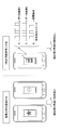
- FIG. 1 shows a transmission image according to an embodiment of the present invention.
- a color image generated by assigning information to each of the three primary colors RGB is displayed on the screen of the transmission apparatus.
- the illustrated transmission image may transmit 3-bit information “101”. Is possible.
- the receiving device can capture a displayed transmission image using an imaging unit such as a built-in camera, and can acquire information from the captured transmission image.
- the present invention will be described with respect to the RGB system.
- the present invention is not limited to the RGB system, and any other suitable color display system capable of displaying a plurality of colors is used. May be.
- the color value to be used may be changed according to the environment in which the transmission device and the reception device are arranged. For example, when the transmitting device and the receiving device are in a dark environment, the use of dark color values may be avoided. By dynamically assigning color values to be used according to the environment in this way, it is possible to capture a color image with higher accuracy.
- the transmission device and / or the reception device is typically a portable information terminal such as a mobile phone terminal or a smartphone, and the transmission device transmits data to be transmitted using an application installed in the terminal. Can be displayed on the display, and the receiving apparatus is an apparatus capable of imaging the display of the transmitting apparatus using an application and an imaging unit installed in the terminal.
- the transmission device and / or the reception device typically includes one or more of various hardware resources such as an auxiliary storage device, a memory device, a CPU (Central Processing Unit), a communication device, a display device, an input device, and an imaging device. Is done.
- the auxiliary storage device is composed of a hard disk, a flash memory, and the like, and stores programs and data for realizing various processes described later.
- the memory device is composed of a RAM (Random Access Memory) or the like, and reads and stores the program from the auxiliary storage device when an instruction to start the program is given.
- the CPU functions as a processor for processing information, and implements various functions described later according to programs stored in the memory device.
- the communication device includes various communication circuits for wired and / or wireless connection with other devices such as a server via a network.
- the display device includes various displays such as an LED display and an organic EL display, and displays various information.
- the input device typically includes operation buttons, a keyboard, a mouse, and the like, and is used by a user of the mobile terminal to input various operation commands.
- the imaging device is typically composed of a digital camera composed of an image sensor such as a CCD, and captures still images and moving images to acquire image data.
- the imaging device may detect the brightness of the environment where the transmission device is placed, and turn on the light when the brightness is lower than the predetermined brightness.
- the transmission device and the reception device according to the present invention are not limited to the hardware configuration described above, and may have any other appropriate hardware configuration such as a circuit capable of realizing various functions described below. Good.
- FIG. 2 is a block diagram illustrating a configuration of a transmission apparatus according to an embodiment of the present invention.
- the transmission device 100 includes a transmission data control unit 110 and a display unit 120.
- the display unit 120 includes an R color control unit 130R, a G color control unit 130G, and a B color control unit 130B, and corresponding R color light emitting units 140R, G color light emitting units 140G, and B color light emitting units 140B.
- the transmission data control unit 110 distributes data to be transmitted to each color of RGB. As described above, when modulation is performed using two color values “255” and “0” for each color, for example, the transmission data control unit 110 transmits data “x 0 x 1 x 2 ... X n to be transmitted. “x 0 x 3 ... x n ” of “x n + 1 x n + 2 ” (where x i is a binary value of “0” or “1”) is allocated to the R color control unit 130R, and “x 1 x 4 ... X n + 1 ”may be distributed to the G color control unit 130G, and“ x 2 x 5 ...
- X n + 2 may be distributed to the B color control unit 130B.
- any one of the three colors RGB may be assigned to transmit a synchronization signal as described later, and the data to be transmitted may be transmitted using the remaining two colors.
- the above distribution method is merely an example, and any other appropriate distribution method can be used, for example, the transmission target data is divided into three in series and distributed to each RGB color.
- the transmission data control unit 110 may add a bit string such as a preamble or an error detection / correction code to data allocated to each color of RGB so that the receiving apparatus 200 can receive the data more reliably.
- the display unit 120 converts the transmission target data received from the transmission data control unit 110 into one or more transmission images, and displays a moving image in the communication area on the display of the transmission device 100.
- the transmission image may be displayed in any suitable shape, but is preferably displayed in a shape suitable for reading by the receiving apparatus 200. For example, a shape in which the receiving device 200 cannot properly recognize the transmission image from the captured image according to the reading angle when the receiving device 200 images the display of the transmitting device 100 is not preferable.
- x i assigned color values "255" in the case of "1”, "x 1 x 4 ⁇ x n + 1 " in the G-color luminescent to emit light by the color value sequence "0/255 " corresponding
- the unit 140G is controlled.
- a color value “255” is assigned, and a B color light emitting unit is configured to emit light by a color value series “0/255...” corresponding to “x 2 x 5 ... x n + 2 ”. 140B is controlled.
- the R color light emitting unit 140R, the G color light emitting unit 140G, and the B color light emitting unit 140B are respectively in accordance with the color value series in each display frame under the control of the R color control unit 130R, the G color control unit 130G, and the B color control unit 130B. Emits the display.
- two color values “0” and “255” are used for each color of the RBG, and therefore the bit string of the data to be transmitted is converted into a blinking pattern of each color.
- FIG. 3 is a block diagram showing a configuration of a receiving apparatus according to an embodiment of the present invention.
- the receiving device 200 includes a moving image capturing unit 210, a communication area extracting unit 220, and a data receiving unit 230.
- the moving image capturing unit 210 captures a moving image composed of one or more transmission images displayed on the display of the transmission apparatus 100, and the communication region extracting unit 220 extracts one or more captured images constituting the captured moving image. To provide.
- the transmission device 100 displays a transmission image as shown in FIG. 1 on the display, the captured image is typically an image including the device body of the transmission device 100 as shown in FIG.
- the communication area extraction unit 220 extracts a communication area to be transmitted by the transmission device 100 from one or more captured images provided from the moving image capturing unit 210, and provides the extracted communication area to the data reception unit 230.
- the captured image is an image including the device main body of the transmission device 100 as illustrated in FIG. 1, the communication region extraction unit 220 extracts a centralized communication region that is transmission data from the captured image.
- the communication area extraction unit 220 may extract a communication area based on the shape of the communication area displayed on the display of the transmission device 100.
- the shape of the communication area cannot be captured correctly depending on the angle at which the receiving apparatus 200 captures the display of the transmitting apparatus 100. For this reason, it is desirable to use a method that uses a predetermined color described later as a synchronization signal so that the shape of the communication area can be correctly recognized.
- the receiving device 200 may photograph the displays of the plurality of transmitting devices 100 at the same time.
- the communication area extraction unit 220 extracts the communication area of each transmission device 100 from the captured image, and provides the extracted plurality of communication areas to the data reception unit 230.
- the receiving device 200 can simultaneously receive data such as profile information of a plurality of transmitting devices 100, which is more efficient one-to-many than one-to-one communication between portable devices using infrared communication according to the prior art. Communication can be realized.
- the transmission device 100 assigns a predetermined one color from the three colors of RGB to a synchronization signal for specifying a communication area, and a communication area extracting unit 220 may extract the communication area using this synchronization signal.
- a communication area extracting unit 220 may extract the communication area using this synchronization signal.
- blue may be assigned as the synchronization signal
- the transmission apparatus 100 may display the communication area inside the blue boundary line.
- the communication area extraction unit 220 extracts the area surrounded by the specified boundary line as the communication area by specifying the blue boundary line in the captured image.
- the transmission device 100 may display the blue synchronization signal over the other colors in the entire communication area.
- the communication area extraction unit 220 extracts a blue component in the captured image and extracts it as a communication area.
- the transmission device 100 may cause the color assigned to the synchronization signal to blink according to a predetermined blinking pattern.
- the communication area extraction unit 220 can identify the communication area with higher accuracy, and is particularly effective for extracting a plurality of communication areas in the above-described one-to-many communication.
- the data receiving unit 230 specifies the color value series of each color of RGB in the communication area received from the communication area extracting unit 220, and specifies the bit series included in the communication area from the specified color value series. For example, when the communication area is configured using two color values “0” and “255” for each color of RGB, 3-bit information can be acquired from one captured image.
- the data receiving unit 230 configures information transmitted from the captured moving image by acquiring and combining 3-bit information from each captured image.
- FIG. 5 is a flowchart showing processing of the transmission device and the reception device according to an embodiment of the present invention.
- the flow is started when transmission data is generated in the transmission device 100 in step S ⁇ b> 101.
- the flow starts.
- step S103 the transmission device 100 distributes data to be transmitted to each color of RGB.
- the transmission device 100 distributes data to be transmitted to the remaining two colors.
- step S105 the transmission apparatus 100 adds a preamble and an error detection / correction code to the data allocated to each color of RGB, and generates a packet for each color.
- the added preamble and error detection / correction code may be configured using any known technique, and by adding such additional data, the receiving apparatus 200 can ensure the packet. It becomes possible to receive.
- step S107 the transmitting apparatus 100 converts the bit series included in the R color packet, the G color packet, and the B color packet into a color value series, and typically, according to the converted color value series of each color.
- a display composed of LEDs is caused to emit light.
- step S201 the receiving device 200 captures a moving image displayed on the display of the transmitting device 100 and acquires the captured moving image.
- step S203 the receiving apparatus 200 extracts a communication area from each captured image constituting the captured moving image.
- step S205 the receiving apparatus 200 stores the image data of the communication area extracted from each captured image in the storage unit.
- step S207 the receiving apparatus 200 performs error detection on each packet based on the error detection / correction code of each color packet of the accumulated image data. If an error is detected in any packet and cannot be corrected (step S207: NG / uncorrectable), the receiving apparatus 200 discards the packet in step S209, returns to step S201, and receives a moving image from the transmitting apparatus 100. Get it again. On the other hand, if no error is detected in any of the packets, or if correction is possible even if an error is detected, the receiving apparatus 200 extracts a data portion from the accumulated packets of each color in step S211.
- step S213 the receiving apparatus 200 combines the data extracted from the packets of the respective colors, and reconstructs the data transmitted from the transmitting apparatus 100.
- step S215 the receiving apparatus 200 outputs the reconstructed data to the storage unit and / or the display.
- FIG. 7 shows a transmission image according to another embodiment of the present invention.
- the transmission device 100 displays two communication areas A and B on the display, and the transmission target is based on the color difference of the color image displayed in each of the communication areas A and B.
- Communicate data In the illustrated embodiment, in the communication area A, each color of RGB is displayed with color values “255”, “0”, and “255”, and in the communication area B, each color of RGB is displayed with a color value “0”. Displayed by “255” and “0”.
- the color difference values of these two color images are “255”, “ ⁇ 255”, and “255” for each color of RGB.
- the transmission device 100 uses 3 bits of “101” by the two communication areas A and B. Information can be sent.
- two color values “255” and “0” are used for each primary color, but a multi-level modulation method using more color values may be used.
- four color values “255”, “170”, “85”, and “0” may be used.
- the corresponding four color difference values are “255”, “85”, “ ⁇ 85”, and “ ⁇ 255”
- the binary value “11” is assigned to the color difference value “255”
- the color difference value “85” is assigned.
- the binary value “10” may be assigned, the binary value “01” may be assigned to the color difference value “ ⁇ 85”, and the binary value “00” may be assigned to the color difference value “ ⁇ 255”.
- 6-bit information can be transmitted by one transmission image using the three primary colors of RGB.
- a pair of two communication areas is used. It becomes possible to avoid the influence of disturbance light by performing the light emission which becomes and taking the difference.
- FIG. 8 shows the effect of the embodiment of the present invention.
- the calculated value shown in FIG. 8 indicates the theoretical value of the time required to transmit an IPv4 address (32 bits) under the same frame rate (30 frames per second).
- the first row of the illustrated table shows the calculation result of the conventional method for transmitting information in a single color, and shows that it takes 2.13 seconds to transmit an IPv4 address.
- the calculation results of the present invention for transmitting information by color images are shown in the second to fifth rows of the illustrated table. It can be understood that the present invention can transmit information in a shorter time than the conventional method, regardless of which method is used.
Landscapes
- Engineering & Computer Science (AREA)
- Computer Networks & Wireless Communication (AREA)
- Signal Processing (AREA)
- Physics & Mathematics (AREA)
- Electromagnetism (AREA)
- Human Computer Interaction (AREA)
- General Physics & Mathematics (AREA)
- Theoretical Computer Science (AREA)
- Computer Hardware Design (AREA)
- Multimedia (AREA)
- Optical Communication System (AREA)
- Two-Way Televisions, Distribution Of Moving Picture Or The Like (AREA)
- Controls And Circuits For Display Device (AREA)
- Color Image Communication Systems (AREA)
- Processing Of Color Television Signals (AREA)
Abstract
Dans l'un de ses modes de réalisation, la présente invention se rapporte à un dispositif de transmission adapté pour transmettre des données au moyen d'une image dynamique. Le dispositif de transmission selon l'invention comprend : un contrôleur de transmission de données, qui est utilisé afin d'assigner les données à une pluralité de couleurs qui composent une image dynamique ; et une section d'affichage, qui est utilisée afin de convertir les données assignées en des séries prédéterminées de valeurs de couleurs en rapport avec chacune de la pluralité de couleurs, et afin d'émettre une lumière de la pluralité de couleurs dans une zone de communication sur un écran d'affichage, conformément aux séries prédéterminées de valeurs de couleurs.
Priority Applications (3)
| Application Number | Priority Date | Filing Date | Title |
|---|---|---|---|
| CN201280056991.4A CN103959749A (zh) | 2011-11-25 | 2012-11-20 | 发送装置、接收装置及方法 |
| US14/354,764 US9571193B2 (en) | 2011-11-25 | 2012-11-20 | Transmitter, receiver, and method |
| EP12851433.8A EP2784949B1 (fr) | 2011-11-25 | 2012-11-20 | Dispositif de transmission, dispositif de réception et procédé correspondant |
Applications Claiming Priority (2)
| Application Number | Priority Date | Filing Date | Title |
|---|---|---|---|
| JP2011257798A JP5608627B2 (ja) | 2011-11-25 | 2011-11-25 | 送信装置、受信装置及び方法 |
| JP2011-257798 | 2011-11-25 |
Publications (1)
| Publication Number | Publication Date |
|---|---|
| WO2013077334A1 true WO2013077334A1 (fr) | 2013-05-30 |
Family
ID=48469777
Family Applications (1)
| Application Number | Title | Priority Date | Filing Date |
|---|---|---|---|
| PCT/JP2012/080102 Ceased WO2013077334A1 (fr) | 2011-11-25 | 2012-11-20 | Dispositif de transmission, dispositif de réception et procédé correspondant |
Country Status (5)
| Country | Link |
|---|---|
| US (1) | US9571193B2 (fr) |
| EP (1) | EP2784949B1 (fr) |
| JP (1) | JP5608627B2 (fr) |
| CN (1) | CN103959749A (fr) |
| WO (1) | WO2013077334A1 (fr) |
Cited By (1)
| Publication number | Priority date | Publication date | Assignee | Title |
|---|---|---|---|---|
| EP2938049A1 (fr) * | 2014-04-01 | 2015-10-28 | Samsung Electronics Co., Ltd | Dispositif électronique et procédé de transmission de données entre un dispositif électronique et son couvercle rabattable |
Families Citing this family (17)
| Publication number | Priority date | Publication date | Assignee | Title |
|---|---|---|---|---|
| JP5942900B2 (ja) * | 2012-04-13 | 2016-06-29 | カシオ計算機株式会社 | 表示装置及びプログラム |
| US20140369696A1 (en) * | 2013-06-18 | 2014-12-18 | Lsi Corporation | Color Coding and Optical Sub-Band Communication Utilizing Color Coding |
| JP6147161B2 (ja) * | 2013-10-03 | 2017-06-14 | 三菱電機株式会社 | 撮像装置、情報表示装置及び情報処理システム |
| KR101575893B1 (ko) | 2013-12-20 | 2015-12-09 | 전자부품연구원 | 영상을 이용한 통신 시스템 및 방법 |
| JP6490481B2 (ja) * | 2014-04-25 | 2019-03-27 | 学校法人東京電機大学 | 可視光通信システム |
| WO2016001972A1 (fr) * | 2014-06-30 | 2016-01-07 | 富士通株式会社 | Appareil d'émission, appareil de réception, système de communication, procédé d'émission et procédé de réception |
| JP6183386B2 (ja) * | 2015-01-28 | 2017-08-23 | カシオ計算機株式会社 | 光通信装置、光推定装置、光通信方法、及び、プログラム |
| JP6459620B2 (ja) * | 2015-02-24 | 2019-01-30 | カシオ計算機株式会社 | 受光ユニット、発光制御方法及びプログラム |
| CN106033980B (zh) * | 2015-03-20 | 2019-02-15 | 北京智谷睿拓技术服务有限公司 | 无线通信方法及无线通信装置 |
| JP6210081B2 (ja) * | 2015-03-23 | 2017-10-11 | カシオ計算機株式会社 | 復号装置、復号方法、及び、プログラム |
| CN106283224B (zh) * | 2015-06-11 | 2019-08-20 | 吉林奇峰化纤股份有限公司 | 一种湿法大有光腈纶的制备方法 |
| CN105227244B (zh) * | 2015-08-26 | 2017-11-28 | 联想(北京)有限公司 | 一种信号发送方法、信号接收方法、发送设备及接收设备 |
| GB201605142D0 (en) | 2016-03-25 | 2016-05-11 | Purelifi Ltd | A camera system |
| ITUA20162205A1 (it) * | 2016-04-01 | 2017-10-01 | Aep Ticketing Solutions S R L | Sistema per la trasmissione e la ricezione di dati attraverso codifica ottica basata su raggi di luce modulati in intensità e cromatismo. |
| CN106788731B (zh) * | 2017-03-17 | 2019-03-01 | 维沃移动通信有限公司 | 数据传输方法及移动终端 |
| CN107370744A (zh) * | 2017-08-02 | 2017-11-21 | 大连三增上学教育科技有限公司 | 一种信息传递方法及系统 |
| US10819437B2 (en) * | 2019-03-05 | 2020-10-27 | Meadowave, Llc | Miniature embedded self-organized optical network |
Citations (5)
| Publication number | Priority date | Publication date | Assignee | Title |
|---|---|---|---|---|
| JPH09233025A (ja) * | 1996-02-28 | 1997-09-05 | Brother Ind Ltd | 光情報伝達装置 |
| JP2003218791A (ja) * | 2002-01-21 | 2003-07-31 | Matsushita Electric Ind Co Ltd | 光伝送システム |
| JP2005136665A (ja) * | 2003-10-30 | 2005-05-26 | Nippon Telegr & Teleph Corp <Ntt> | データ信号の送信方法と受信方法及びその装置、システム、プログラム並びに記録媒体 |
| JP2009159572A (ja) * | 2007-12-28 | 2009-07-16 | Waso-Giken Inc | 受光ユニットおよび光通信装置 |
| JP2009290361A (ja) * | 2008-05-27 | 2009-12-10 | Panasonic Electric Works Co Ltd | 可視光通信システム |
Family Cites Families (6)
| Publication number | Priority date | Publication date | Assignee | Title |
|---|---|---|---|---|
| JP2002218261A (ja) * | 2001-01-23 | 2002-08-02 | Minolta Co Ltd | 画像情報伝送方法、画像情報作成装置、画像情報出力装置、画像情報作成プログラム、画像情報出力プログラム、これらのプログラムを記録した記録媒体及び画像情報伝送システム |
| US20050254714A1 (en) * | 2004-05-13 | 2005-11-17 | Ramakrishna Anne | Systems and methods for data transfer with camera-enabled devices |
| US7830357B2 (en) * | 2004-07-28 | 2010-11-09 | Panasonic Corporation | Image display device and image display system |
| US20060256070A1 (en) * | 2005-05-13 | 2006-11-16 | Research In Motion Limited | Communications system including units with LCD optical transmitters/receivers and related methods |
| US7850067B1 (en) * | 2007-11-27 | 2010-12-14 | Sprint Communications Company L.P. | Color bar codes |
| CN101951320A (zh) * | 2010-09-29 | 2011-01-19 | 北京天地融科技有限公司 | 一种动态密码的实现方法、装置和系统 |
-
2011
- 2011-11-25 JP JP2011257798A patent/JP5608627B2/ja active Active
-
2012
- 2012-11-20 WO PCT/JP2012/080102 patent/WO2013077334A1/fr not_active Ceased
- 2012-11-20 EP EP12851433.8A patent/EP2784949B1/fr not_active Not-in-force
- 2012-11-20 CN CN201280056991.4A patent/CN103959749A/zh active Pending
- 2012-11-20 US US14/354,764 patent/US9571193B2/en not_active Expired - Fee Related
Patent Citations (5)
| Publication number | Priority date | Publication date | Assignee | Title |
|---|---|---|---|---|
| JPH09233025A (ja) * | 1996-02-28 | 1997-09-05 | Brother Ind Ltd | 光情報伝達装置 |
| JP2003218791A (ja) * | 2002-01-21 | 2003-07-31 | Matsushita Electric Ind Co Ltd | 光伝送システム |
| JP2005136665A (ja) * | 2003-10-30 | 2005-05-26 | Nippon Telegr & Teleph Corp <Ntt> | データ信号の送信方法と受信方法及びその装置、システム、プログラム並びに記録媒体 |
| JP2009159572A (ja) * | 2007-12-28 | 2009-07-16 | Waso-Giken Inc | 受光ユニットおよび光通信装置 |
| JP2009290361A (ja) * | 2008-05-27 | 2009-12-10 | Panasonic Electric Works Co Ltd | 可視光通信システム |
Non-Patent Citations (1)
| Title |
|---|
| See also references of EP2784949A4 * |
Cited By (3)
| Publication number | Priority date | Publication date | Assignee | Title |
|---|---|---|---|---|
| EP2938049A1 (fr) * | 2014-04-01 | 2015-10-28 | Samsung Electronics Co., Ltd | Dispositif électronique et procédé de transmission de données entre un dispositif électronique et son couvercle rabattable |
| US9509360B2 (en) | 2014-04-01 | 2016-11-29 | Samsung Electronics Co., Ltd. | Electronic device and method of transmitting data between electronic device and flip cover thereof |
| CN106170931A (zh) * | 2014-04-01 | 2016-11-30 | 三星电子株式会社 | 在电子设备及其翻盖保护套之间发射数据的电子设备和方法 |
Also Published As
| Publication number | Publication date |
|---|---|
| JP2013115497A (ja) | 2013-06-10 |
| EP2784949B1 (fr) | 2018-08-22 |
| EP2784949A1 (fr) | 2014-10-01 |
| US9571193B2 (en) | 2017-02-14 |
| JP5608627B2 (ja) | 2014-10-15 |
| EP2784949A4 (fr) | 2015-08-12 |
| US20140241732A1 (en) | 2014-08-28 |
| CN103959749A (zh) | 2014-07-30 |
Similar Documents
| Publication | Publication Date | Title |
|---|---|---|
| JP5608627B2 (ja) | 送信装置、受信装置及び方法 | |
| JP6053822B2 (ja) | フリッカーフリーのカラー可視光通信システム | |
| WO2022019437A1 (fr) | Fusion d'images à expositions multiples guidée | |
| US10218440B2 (en) | Method for visible light communication using display colors and pattern types of display | |
| KR102857557B1 (ko) | 높은 동적 범위 이미지들을 생성, 스트리밍, 및 렌더링하기 위한 장치 및 방법 | |
| RU2014137137A (ru) | Дистанционное управление источником света | |
| JP6362608B2 (ja) | 表示方法および表示装置 | |
| US10750080B2 (en) | Information processing device, information processing method, and program | |
| US9100579B2 (en) | Modification of a video signal of an object exposed to ambient light and light emitted from a display screen | |
| Jung et al. | Complementary Color Barcode‐Based Optical Camera Communications | |
| CN108781268A (zh) | 图像处理装置和方法 | |
| JP5713061B2 (ja) | 情報送信装置、情報送信方法、及び、プログラム | |
| JP2008187362A (ja) | プロジェクタおよび投写画像調整方法 | |
| CN105992006B (zh) | 解码装置、解码方法以及计算机可读介质 | |
| CN105321450B (zh) | 显示装置、显示控制方法以及记录介质 | |
| CN106028015B (zh) | 颜色处理装置和方法以及颜色处理系统 | |
| JP2013009072A5 (ja) | 情報伝送システム、情報送信装置、情報受信装置、情報伝送方法、情報送信方法、情報受信方法、及び、プログラム | |
| WO2016059860A1 (fr) | Système de traitement d'informations, dispositif de traitement d'informations, et terminal de traitement d'informations | |
| CN117692788B (zh) | 一种图像处理方法及电子设备 | |
| CN112312122B (zh) | 摄像头保护膜的检测方法及装置 | |
| CN116668656A (zh) | 图像处理方法及电子设备 | |
| US10367581B2 (en) | Notification device, notification method, and non-transitory recording medium | |
| JP2019124875A (ja) | 識別情報設定装置、画像表示装置、識別情報設定方法 | |
| CN112753284A (zh) | 通过顺序开启光源创建组合图像 | |
| CN112788311B (zh) | 信息获取方法、信息获取装置 |
Legal Events
| Date | Code | Title | Description |
|---|---|---|---|
| 121 | Ep: the epo has been informed by wipo that ep was designated in this application |
Ref document number: 12851433 Country of ref document: EP Kind code of ref document: A1 |
|
| WWE | Wipo information: entry into national phase |
Ref document number: 14354764 Country of ref document: US |
|
| WWE | Wipo information: entry into national phase |
Ref document number: 2012851433 Country of ref document: EP |
|
| NENP | Non-entry into the national phase |
Ref country code: DE |