WO2013080525A1 - インジェクタの制御方法 - Google Patents
インジェクタの制御方法 Download PDFInfo
- Publication number
- WO2013080525A1 WO2013080525A1 PCT/JP2012/007613 JP2012007613W WO2013080525A1 WO 2013080525 A1 WO2013080525 A1 WO 2013080525A1 JP 2012007613 W JP2012007613 W JP 2012007613W WO 2013080525 A1 WO2013080525 A1 WO 2013080525A1
- Authority
- WO
- WIPO (PCT)
- Prior art keywords
- injector
- urea water
- pump
- malfunction
- urea
- Prior art date
- Legal status (The legal status is an assumption and is not a legal conclusion. Google has not performed a legal analysis and makes no representation as to the accuracy of the status listed.)
- Ceased
Links
Images



Classifications
-
- F—MECHANICAL ENGINEERING; LIGHTING; HEATING; WEAPONS; BLASTING
- F01—MACHINES OR ENGINES IN GENERAL; ENGINE PLANTS IN GENERAL; STEAM ENGINES
- F01N—GAS-FLOW SILENCERS OR EXHAUST APPARATUS FOR MACHINES OR ENGINES IN GENERAL; GAS-FLOW SILENCERS OR EXHAUST APPARATUS FOR INTERNAL-COMBUSTION ENGINES
- F01N3/00—Exhaust or silencing apparatus having means for purifying, rendering innocuous, or otherwise treating exhaust
- F01N3/08—Exhaust or silencing apparatus having means for purifying, rendering innocuous, or otherwise treating exhaust for rendering innocuous
- F01N3/10—Exhaust or silencing apparatus having means for purifying, rendering innocuous, or otherwise treating exhaust for rendering innocuous by thermal or catalytic conversion of noxious components of exhaust
- F01N3/18—Exhaust or silencing apparatus having means for purifying, rendering innocuous, or otherwise treating exhaust for rendering innocuous by thermal or catalytic conversion of noxious components of exhaust characterised by methods of operation; Control
- F01N3/20—Exhaust or silencing apparatus having means for purifying, rendering innocuous, or otherwise treating exhaust for rendering innocuous by thermal or catalytic conversion of noxious components of exhaust characterised by methods of operation; Control specially adapted for catalytic conversion
- F01N3/206—Adding periodically or continuously substances to exhaust gases for promoting purification, e.g. catalytic material in liquid form, NOx reducing agents
- F01N3/208—Control of selective catalytic reduction [SCR], e.g. by adjusting the dosing of reducing agent
-
- F—MECHANICAL ENGINEERING; LIGHTING; HEATING; WEAPONS; BLASTING
- F01—MACHINES OR ENGINES IN GENERAL; ENGINE PLANTS IN GENERAL; STEAM ENGINES
- F01N—GAS-FLOW SILENCERS OR EXHAUST APPARATUS FOR MACHINES OR ENGINES IN GENERAL; GAS-FLOW SILENCERS OR EXHAUST APPARATUS FOR INTERNAL-COMBUSTION ENGINES
- F01N11/00—Monitoring or diagnostic devices for exhaust-gas treatment apparatus
-
- F—MECHANICAL ENGINEERING; LIGHTING; HEATING; WEAPONS; BLASTING
- F01—MACHINES OR ENGINES IN GENERAL; ENGINE PLANTS IN GENERAL; STEAM ENGINES
- F01N—GAS-FLOW SILENCERS OR EXHAUST APPARATUS FOR MACHINES OR ENGINES IN GENERAL; GAS-FLOW SILENCERS OR EXHAUST APPARATUS FOR INTERNAL-COMBUSTION ENGINES
- F01N2550/00—Monitoring or diagnosing the deterioration of exhaust systems
- F01N2550/05—Systems for adding substances into exhaust
-
- F—MECHANICAL ENGINEERING; LIGHTING; HEATING; WEAPONS; BLASTING
- F01—MACHINES OR ENGINES IN GENERAL; ENGINE PLANTS IN GENERAL; STEAM ENGINES
- F01N—GAS-FLOW SILENCERS OR EXHAUST APPARATUS FOR MACHINES OR ENGINES IN GENERAL; GAS-FLOW SILENCERS OR EXHAUST APPARATUS FOR INTERNAL-COMBUSTION ENGINES
- F01N2610/00—Adding substances to exhaust gases
- F01N2610/02—Adding substances to exhaust gases the substance being ammonia or urea
-
- F—MECHANICAL ENGINEERING; LIGHTING; HEATING; WEAPONS; BLASTING
- F01—MACHINES OR ENGINES IN GENERAL; ENGINE PLANTS IN GENERAL; STEAM ENGINES
- F01N—GAS-FLOW SILENCERS OR EXHAUST APPARATUS FOR MACHINES OR ENGINES IN GENERAL; GAS-FLOW SILENCERS OR EXHAUST APPARATUS FOR INTERNAL-COMBUSTION ENGINES
- F01N2610/00—Adding substances to exhaust gases
- F01N2610/14—Arrangements for the supply of substances, e.g. conduits
- F01N2610/1433—Pumps
- F01N2610/144—Control thereof
-
- F—MECHANICAL ENGINEERING; LIGHTING; HEATING; WEAPONS; BLASTING
- F01—MACHINES OR ENGINES IN GENERAL; ENGINE PLANTS IN GENERAL; STEAM ENGINES
- F01N—GAS-FLOW SILENCERS OR EXHAUST APPARATUS FOR MACHINES OR ENGINES IN GENERAL; GAS-FLOW SILENCERS OR EXHAUST APPARATUS FOR INTERNAL-COMBUSTION ENGINES
- F01N2610/00—Adding substances to exhaust gases
- F01N2610/14—Arrangements for the supply of substances, e.g. conduits
- F01N2610/1453—Sprayers or atomisers; Arrangement thereof in the exhaust apparatus
- F01N2610/146—Control thereof, e.g. control of injectors or injection valves
-
- F—MECHANICAL ENGINEERING; LIGHTING; HEATING; WEAPONS; BLASTING
- F01—MACHINES OR ENGINES IN GENERAL; ENGINE PLANTS IN GENERAL; STEAM ENGINES
- F01N—GAS-FLOW SILENCERS OR EXHAUST APPARATUS FOR MACHINES OR ENGINES IN GENERAL; GAS-FLOW SILENCERS OR EXHAUST APPARATUS FOR INTERNAL-COMBUSTION ENGINES
- F01N2900/00—Details of electrical control or of the monitoring of the exhaust gas treating apparatus
- F01N2900/06—Parameters used for exhaust control or diagnosing
- F01N2900/18—Parameters used for exhaust control or diagnosing said parameters being related to the system for adding a substance into the exhaust
- F01N2900/1806—Properties of reducing agent or dosing system
- F01N2900/1808—Pressure
-
- Y—GENERAL TAGGING OF NEW TECHNOLOGICAL DEVELOPMENTS; GENERAL TAGGING OF CROSS-SECTIONAL TECHNOLOGIES SPANNING OVER SEVERAL SECTIONS OF THE IPC; TECHNICAL SUBJECTS COVERED BY FORMER USPC CROSS-REFERENCE ART COLLECTIONS [XRACs] AND DIGESTS
- Y02—TECHNOLOGIES OR APPLICATIONS FOR MITIGATION OR ADAPTATION AGAINST CLIMATE CHANGE
- Y02T—CLIMATE CHANGE MITIGATION TECHNOLOGIES RELATED TO TRANSPORTATION
- Y02T10/00—Road transport of goods or passengers
- Y02T10/10—Internal combustion engine [ICE] based vehicles
- Y02T10/12—Improving ICE efficiencies
-
- Y—GENERAL TAGGING OF NEW TECHNOLOGICAL DEVELOPMENTS; GENERAL TAGGING OF CROSS-SECTIONAL TECHNOLOGIES SPANNING OVER SEVERAL SECTIONS OF THE IPC; TECHNICAL SUBJECTS COVERED BY FORMER USPC CROSS-REFERENCE ART COLLECTIONS [XRACs] AND DIGESTS
- Y02—TECHNOLOGIES OR APPLICATIONS FOR MITIGATION OR ADAPTATION AGAINST CLIMATE CHANGE
- Y02T—CLIMATE CHANGE MITIGATION TECHNOLOGIES RELATED TO TRANSPORTATION
- Y02T10/00—Road transport of goods or passengers
- Y02T10/10—Internal combustion engine [ICE] based vehicles
- Y02T10/40—Engine management systems
Definitions
- the present invention relates to an injector control method.
- a selective reduction catalyst that includes a particulate filter that collects particulates in exhaust gas in the middle of an exhaust pipe, and that can selectively react NOx with ammonia even in the presence of oxygen on the downstream side of the particulate filter. It is considered that urea water is added as a reducing agent between the selective reduction catalyst and the particulate filter to simultaneously reduce particulates and NOx.
- a particulate filter 3 for collecting particulates in the exhaust gas 1 and a downstream side of the particulate filter 3.
- a selective reduction catalyst 4 having the property of selectively reacting NOx with ammonia even in the presence of oxygen is held in parallel by the casings 5 and 6, and arranged in parallel with the outlet end of the particulate filter 3.
- the inlet side end portion of the selective catalytic reduction catalyst 4 is connected by a communication channel 7 having an S-shaped structure, and the exhaust gas 1 discharged from the outlet side end portion of the particulate filter 3 is folded back in the reverse direction.
- An exhaust purification device has been devised that is introduced into the inlet end of the selective catalytic reduction catalyst 4.
- the communication channel 7 surrounds the outlet side end of the particulate filter 3 and collects the exhaust gas 1 immediately after exiting from the outlet side end while changing the direction in a substantially perpendicular direction.
- the S-shaped structure is formed by the gas dispersion chamber 7C surrounding the inlet side end so that the dispersed exhaust gas 1 can be introduced into the inlet side end of the selective catalytic reduction catalyst 4 while being dispersed.
- the injector 8 for adding urea water into the mixing pipe 7B is provided at the central position of the inlet side end of the mixing pipe 7B. It is equipped toward the outlet end side.
- an oxidation catalyst 9 that oxidizes unburned fuel in the exhaust gas 1 is provided in the front stage in the casing 5 in which the particulate filter 3 is held,
- an ammonia reduction catalyst 10 that oxidizes surplus ammonia is provided at the rear stage in the casing 6 in which the selective catalytic reduction catalyst 4 is held.
- particulates in the exhaust gas 1 are collected by the particulate filter 3, and urea water is fed from the injector 8 into the exhaust gas 1 in the middle of the mixing pipe 7 B on the downstream side. Is added to the catalyst and thermally decomposed into ammonia and carbon dioxide, and the NOx in the exhaust gas 1 is reduced and purified well by the ammonia on the selective catalytic reduction catalyst 4, so that simultaneous reduction of particulates and NOx in the exhaust gas 1 is achieved. It will be illustrated.
- the exhaust gas 1 discharged from the outlet end portion of the particulate filter 3 is folded in the reverse direction by the connecting flow path 7 and then introduced into the inlet end portion of the adjacent selective catalytic reduction catalyst 4. Therefore, a long distance from the urea water addition position to the selective catalytic reduction catalyst 4 is secured, and a sufficient reaction time is secured for ammonia to be generated from the urea water.
- the particulate filter 3 and the selective catalytic reduction catalyst 4 are arranged in parallel, and the communication flow path 7 is arranged between the particulate filter 3 and the selective catalytic reduction catalyst 4, so that the whole The configuration becomes compact, and the mountability to the vehicle is greatly improved.
- urea crystals may be deposited inside the nozzle under special conditions such as when the engine is suddenly stopped from an operation state where the exhaust temperature is high. In some cases, the precipitated urea crystals are fixed, causing a temporary malfunction that makes it impossible to inject urea water.
- urea water is purged to the urea water tank side at the same time as key-off, and measures are taken to prevent freezing of urea water while the engine is stopped in cold districts (for example, the following)
- urea water is fed while the injector 8 is idled and air in the path is extracted.
- the present invention has been made in view of the above-described circumstances, and an object of the present invention is to make it possible to quickly recover from a temporary malfunction of an injector due to the fixation of urea crystals.
- the present invention relates to a control method for recovering a temporary malfunction caused by the fixation of urea crystals in an injector that adds urea water to exhaust gas, and a path for supplying urea water descends from above the injector.
- the piping layout is configured to connect to the injector, and when the malfunction of the injector is determined, the pump is stopped after an operation to suck the urea water in the path once, and the pump is re-driven after a predetermined time Thus, the operation failure of the injector is determined again.
- the present invention it is preferable to perform a test injection of urea water after boosting the urea water to a predetermined pressure with a pump, and to determine the malfunction of the injector when there is no pressure drop during the test injection, It is preferable to determine the abnormality of the injector when the determination of the malfunction of the injector is repeated a predetermined number of times.
- the injector control method of the present invention by interposing an operation of once sucking back urea water in the path, the pump is stopped, and the pump is re-driven after a predetermined time.
- the interface with air can be greatly swung to facilitate the replacement of urea water with air, so that urea water can flow down in the path instead of the air rising in the path to reach the injector and make urea crystals It is possible to quickly recover from a temporary malfunction of the injector due to melting and fixation of the urea crystal, and to greatly reduce the frequency of diagnosis as an abnormality of the injector in the self-diagnosis function of the vehicle. The effects can be achieved.
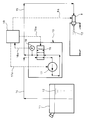
- Reference numeral 11 in FIG. 2 denotes a urea water tank storing urea water 12, and 13 denotes a urea water tank 11 through a suction line 14.
- a pump that sucks up urea water 12 and delivers the urea water 12 to an injector 8 through a pressure line 15 is shown.
- the pressure line 15 forming a path for supplying the urea water 12 to the injector 8 is configured to have a piping layout that descends from above the injector 8 and connects to the injector 8.
- the pump 13 that supplies the urea water 12 to the injector 8 includes a flow path switching valve 16 that can switch between two forward and reverse positions, and a pump body 17 that substantially takes in and discharges the urea water 12.
- the urea water 12 in the pressure line 15 can be sucked back by the pump body 17 by switching the position of the flow path switching valve 16 from the state of FIG. 2 to the state of FIG.
- the flow path switching valve 16 is switched to the reverse position (position shown in FIG. 3) simultaneously with the key-off, and the urea water 12 is purged to the urea water tank 11 side by driving the pump main body 17. Measures are taken to prevent freezing of urea water while the engine is stopped on the ground.
- the pump 13 is also provided with a pressure sensor 18 for detecting the pressure of the urea water 12 in the pressure line 15, and a detection signal 18a from the pressure sensor 18 is supplied to the injector 8, the flow path switching valve 16, the pump.
- the operation of the main body 17 is input to the control device 19 that controls the control signals 8a, 16a, and 17a, and the malfunction of the injector 8 is determined based on the detected value by the pressure sensor 18.
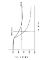
- the urea water 12 in the suction line 14 is boosted to a predetermined pressure (900 kPa in the example of FIG. 4) by the pump 13, and then the nozzle of the injector 8 is fully opened to perform test injection.
- a predetermined pressure 900 kPa in the example of FIG. 4
- the urea water 12 is injected to cause a pressure drop of a predetermined value or more (pressure drop below the threshold in FIG. 4). Occurring and confirming a pressure drop that is less than or equal to the threshold in FIG. 4 at an appropriate detection timing after injection.
- control device 19 when a temporary malfunction due to urea crystal sticking of the injector 8 is determined, the temporary malfunction of the injector 8 due to urea crystal sticking is promptly determined according to the flowchart shown in FIG. Measures to recover are being taken.
- step S1 the determination number of the abnormality counter becomes “0”, and then in step S2, the pump 13 is driven and the suction line 14 is turned on.
- step S3 the test injection of the injector 8 is performed in the next step S3, and the presence or absence of malfunction of the injector 8 based on the pressure drop as described above. Is determined, and if it is determined that the operation of the injector 8 is normal, the determination ends.
- step S4 the number of determinations of the abnormality counter becomes “+1”, and in the next step S5, the number of determinations of the abnormality counter is a predetermined determination number (for example, 10 times). If not, the process proceeds to step S6, where the operation of switching back the flow path switching valve 16 to the reverse position (position in FIG. 3) and driving the pump 13 to once suck the urea water 12 in the pressure line 15 is performed. Done.
- the urea water 12 in the pressure line 15 is not purged to the urea water tank 11 side like when the engine is stopped. It is enough to suck back only a small distance.
- step S 7 After performing the operation of sucking back the urea water 12, the pump 13 is stopped in step S 7, and then in step S 8, after waiting for a predetermined time, the process returns to step S 2. The malfunction is judged again.
- step S5 If it is confirmed in step S5 that the number of determinations of the abnormality counter exceeds a predetermined number of determinations (for example, 10 times), a diagnosis is made as an abnormality of the injector 8 by the vehicle self-diagnosis function. Become.
- the pump 13 is stopped from the beginning, and after a predetermined time, the pump 13 is driven again to determine the malfunction of the injector 8 again. Since it is, the interface between the urea water 12 and the air in the pressure line 15 is larger shaken been to easily occur substituted urea water 12 and air.
- the operation of temporarily sucking back the urea water 12 in the pressure line 15 is interposed, the pump 13 is stopped, and the pump 13 is restarted after a predetermined time. Since the urea water 12 and the air can be easily replaced by greatly shaking the interface between the urea water 12 and the air, the urea water 12 is allowed to flow down in the pressure line 15 in place of the air floating in the pressure line 15. As a result, it is possible to reach the injector 8 to melt the urea crystal, and to quickly recover from a temporary malfunction of the injector 8 due to the fixation of the urea crystal, which is diagnosed as an abnormality of the injector 8 in the self-diagnosis function of the vehicle. The frequency can be greatly reduced.
Landscapes
- Engineering & Computer Science (AREA)
- Chemical & Material Sciences (AREA)
- Chemical Kinetics & Catalysis (AREA)
- Combustion & Propulsion (AREA)
- Mechanical Engineering (AREA)
- General Engineering & Computer Science (AREA)
- Health & Medical Sciences (AREA)
- Toxicology (AREA)
- Exhaust Gas After Treatment (AREA)
Abstract
排気ガス中に尿素水12を添加するインジェクタ8の尿素結晶の固着による一時的な作動不良を回復させるための制御方法に関し、尿素水12を供給する経路(サクションライン14)がインジェクタ8より上方から下降して該インジェクタ8に接続するように配管レイアウトを構成し、インジェクタ8の作動不良が判定された時に、経路(サクションライン14)内の尿素水12を一旦吸い戻す操作を介在させてからポンプ13を停止し、所定時間後にポンプ13を再駆動してインジェクタ8の作動不良の判定を再び行う。
Description
本発明は、インジェクタの制御方法に関するものである。
近年、排気管の途中に排気ガス中のパティキュレートを捕集するパティキュレートフィルタを備えると共に、該パティキュレートフィルタの下流側に酸素共存下でも選択的にNOxをアンモニアと反応させ得る選択還元型触媒を備え、該選択還元型触媒と前記パティキュレートフィルタとの間に還元剤として尿素水を添加してパティキュレートとNOxの同時低減を図ることが考えられている。
このようにする場合、選択還元型触媒への尿素水の添加がパティキュレートフィルタと選択還元型触媒との間で行われることになるため、排気ガス中に添加された尿素水がアンモニアと炭酸ガスに熱分解されるまでの十分な反応時間を確保しようとすれば、尿素水の添加位置から選択還元型触媒までの距離を長くする必要があるが、パティキュレートフィルタと選択還元型触媒とを十分な距離を隔てて離間配置させてしまうと、車両への搭載性が著しく損なわれるという不具合がある。
そこで、図1に示す如く、エンジンからの排気ガス1が流通する排気管2の途中に、排気ガス1中のパティキュレートを捕集するパティキュレートフィルタ3と、該パティキュレートフィルタ3の下流側に酸素共存下でも選択的にNOxをアンモニアと反応させ得る性質を備えた選択還元型触媒4とをケーシング5,6により夫々抱持して並列に配置し、パティキュレートフィルタ3の出側端部と選択還元型触媒4の入側端部との間をS字構造の連絡流路7により接続し、パティキュレートフィルタ3の出側端部から排出された排気ガス1が逆向きに折り返されて隣の選択還元型触媒4の入側端部に導入されるようにした排気浄化装置が創案されている。
ここで、前記連絡流路7は、パティキュレートフィルタ3の出側端部を包囲し且つ該出側端部から出た直後の排気ガス1を略直角な向きに方向転換させつつ集合せしめるガス集合室7Aと、該ガス集合室7Aで集められた排気ガス1をパティキュレートフィルタ3の排気流れと逆向きに抜き出すミキシングパイプ7Bと、該ミキシングパイプ7Bにより導かれた排気ガス1を略直角な向きに方向転換させつつ分散せしめ且つその分散された排気ガス1を選択還元型触媒4の入側端部に導入し得るよう該入側端部を包囲するガス分散室7CとによりS字構造を成すように構成されており、前記ミキシングパイプ7Bの入側端部の中心位置には、該ミキシングパイプ7B内に尿素水を添加するためのインジェクタ8が前記ミキシングパイプ7Bの出側端部側へ向けて装備されている。
尚、ここに図示している例では、パティキュレートフィルタ3が抱持されているケーシング5内の前段に、排気ガス1中の未燃燃料分を酸化処理する酸化触媒9が装備されており、また、選択還元型触媒4が抱持されているケーシング6内の後段には、余剰のアンモニアを酸化処理するアンモニア低減触媒10が装備されている。
そして、このような構成を採用すれば、パティキュレートフィルタ3により排気ガス1中のパティキュレートが捕集されると共に、その下流側のミキシングパイプ7Bの途中でインジェクタ8から尿素水が排気ガス1中に添加されてアンモニアと炭酸ガスに熱分解され、選択還元型触媒4上で排気ガス1中のNOxがアンモニアにより良好に還元浄化される結果、排気ガス1中のパティキュレートとNOxの同時低減が図られることになる。
この際、パティキュレートフィルタ3の出側端部から排出された排気ガス1が連絡流路7により逆向きに折り返されてから隣の選択還元型触媒4の入側端部に導入されるようになっているので、尿素水の添加位置から選択還元型触媒4までの距離が長く確保され、尿素水からアンモニアが生成されるのに十分な反応時間が確保される。
しかも、パティキュレートフィルタ3と選択還元型触媒4とが並列に配置され、これらパティキュレートフィルタ3と選択還元型触媒4との間に沿うように連絡流路7が配置されているので、その全体構成がコンパクトなものとなって車両への搭載性が大幅に向上されることになる。
前述の如き排気浄化装置に備えられる尿素水添加用のインジェクタ8では、排気温度の高い運転状態からエンジンを急停止した場合等の特別な条件下でノズル内部に尿素結晶を析出してしまうことがあり、その析出した尿素結晶が固着することで尿素水の噴射ができなくなる一時的な作動不良を起こすことがある。
即ち、エンジンの停止時には、キーオフと同時に尿素水が尿素水タンク側へパージされ、寒冷地等におけるエンジン停止中の尿素水の凍結を防止する措置が採られるようになっているため(例えば下記の特許文献1等を参照)、次にエンジンを始動する際には、インジェクタ8を空打ちして経路内の空気を抜きながら尿素水を送り込んでいくことになる。
この際、インジェクタ8のノズルが尿素結晶で詰まっていると、空打ちによる空気抜きが行われないため、ポンプにより送り込まれる尿素水が空気を圧縮しながら進むもののインジェクタ8までは到らず、該インジェクタ8のノズルまで尿素水を送り込んで尿素結晶を溶かすことができないという事態に陥ることがある。
このような事態に陥った場合、従来においては、尿素水を送り出すポンプを一旦停止して尿素水の経路を減圧し、所定時間経過後にポンプを再度駆動して試験噴射を実施するという操作を繰り返し、減圧と加圧を交互に繰り返すことで尿素結晶の詰まりを解消してインジェクタ8の回復を図るようにしている。
しかしながら、インジェクタ8のノズル内における尿素結晶の固着の程度が強い場合、ポンプを間欠的に運転して減圧と加圧を繰り返すだけでは十分な回復が図れないことがあり、本来ならば尿素水に触れることで簡単に尿素結晶が溶けてインジェクタ8を正常な作動状態に戻せるはずの一時的な不具合であるのに、インジェクタ8の作動不良が繰り返されることで車両の自己診断機能にインジェクタ8の異常として診断されてしまうという問題があった。
本発明は上述の実情に鑑みてなしたもので、尿素結晶の固着による一時的なインジェクタの作動不良を速やかに回復し得るようにすることを目的とする。
本発明は、排気ガス中に尿素水を添加するインジェクタの尿素結晶の固着による一時的な作動不良を回復させるための制御方法であって、尿素水を供給する経路がインジェクタより上方から下降して該インジェクタに接続するように配管レイアウトを構成し、インジェクタの作動不良が判定された時に、経路内の尿素水を一旦吸い戻す操作を介在させてからポンプを停止し、所定時間後にポンプを再駆動してインジェクタの作動不良の判定を再び行うことを特徴とするものである。
而して、排気温度の高い運転状態からエンジンを急停止した場合等にインジェクタのノズル内部に尿素結晶が析出し、その尿素結晶が固着して尿素水の噴射ができなくなる一時的な作動不良が起きてしまうと、次にエンジンを始動する際にインジェクタを空打ちして経路内の空気を抜きながら尿素水を送り込もうとしても、経路内の空気が抜けないためにポンプにより送り込まれる尿素水がインジェクタまで到達できない事態に陥るが、該インジェクタの作動不良が判定された時に、経路内の尿素水を一旦吸い戻す操作を介在させてからポンプを停止し、所定時間後にポンプを再駆動してインジェクタの作動不良の判定を再び行うようにしているので、経路内で尿素水と空気との界面が大きく揺り動かされて尿素水と空気の置換が起こり易くなる。
即ち、相対的に比重の小さい空気が経路内を浮上し易くなる一方、これと入れ替わりに尿素水が経路内を流下してインジェクタまで到達し易くなるので、該インジェクタのノズル内まで尿素水が到達する機会が大幅に増加されることになり、該尿素水がインジェクタのノズル内まで到達しさえすれば、該ノズル内に固着した尿素結晶が溶かされてインジェクタが正常な作動状態に回復することになる。
また、本発明においては、ポンプで尿素水を所定圧力まで昇圧した後に尿素水の試験噴射を実施し、その試験噴射時に圧力低下が無い場合にインジェクタの作動不良を判定することが好ましく、更には、インジェクタの作動不良の判定が所定回数繰り返された時にインジェクタの異常を判定することが好ましい。
上記した本発明のインジェクタの制御方法によれば、経路内の尿素水を一旦吸い戻す操作を介在させてからポンプを停止して所定時間後にポンプを再駆動することにより、経路内で尿素水と空気との界面を大きく揺り動かして尿素水と空気の置換を起こり易くすることができるので、経路内を浮上する空気と入れ替わりに尿素水を経路内で流下せしめることによりインジェクタまで到達させて尿素結晶を溶かし、該尿素結晶の固着による一時的なインジェクタの作動不良を速やかに回復することができ、車両の自己診断機能にインジェクタの異常として診断される頻度を大幅に低減することができる等種々の優れた効果を奏し得る。
以下本発明の実施例を図面を参照しつつ説明する。
図2~図5は本発明の一実施例を示すもので、図2中における符号の11は尿素水12を貯留している尿素水タンク、13は該尿素水タンク11からサクションライン14を介し尿素水12を吸い上げ且つその尿素水12をプレッシャーライン15を介しインジェクタ8へ送り出すポンプを示している。
ここで、尿素水12をインジェクタ8へ供給する経路を成しているプレッシャーライン15は、インジェクタ8より上方から下降して該インジェクタ8に接続するような配管レイアウトで構成されている。
また、尿素水12をインジェクタ8へ供給するポンプ13は、正逆二つのポジションを切り替え可能に備えた流路切替バルブ16と、尿素水12の吸排を実質的に担うポンプ本体17とを備えており、前記流路切替バルブ16のポジションを図2の状態から図3の状態に切り替えることにより、プレッシャーライン15の尿素水12をポンプ本体17で吸い戻すこともできるようになっている。
即ち、エンジンの停止時には、キーオフと同時に流路切替バルブ16が逆向きのポジション(図3のポジション)に切り替えられ、尿素水12がポンプ本体17の駆動により尿素水タンク11側へパージされ、寒冷地等におけるエンジン停止中の尿素水の凍結を防止する措置が採られるようになっている。
また、前記ポンプ13内には、プレッシャーライン15の尿素水12の圧力を検出する圧力センサ18も備えられており、該圧力センサ18の検出信号18aが、インジェクタ8、流路切替バルブ16、ポンプ本体17の操作を制御信号8a,16a,17aにより制御している制御装置19に入力され、前記圧力センサ18による検出値に基づいてインジェクタ8の作動不良の判定が行われるようになっている。
即ち、図4のグラフに実線の曲線で示す如く、サクションライン14の尿素水12をポンプ13により所定圧(図4の例では900kPa)まで昇圧してからインジェクタ8のノズルを全開にして試験噴射を行い、その噴射後の適宜な検出タイミングで所定以上の圧力降下(図4中の閾値以下の圧力降下)が認められない場合にインジェクタ8の作動不良が判定されるようになっている。
尚、インジェクタ8の作動が正常である場合には、図4のグラフに鎖線で示す如く、尿素水12が噴射されることで所定以上の圧力降下(図4中の閾値以下の圧力降下)が起こり、噴射後の適宜な検出タイミングで図4中の閾値以下となるような圧力降下が確認できることになる。
また、制御装置19においては、インジェクタ8の尿素結晶の固着による一時的な作動不良が判定された時に、図5に示す如きフローチャートに従い尿素結晶の固着による一時的なインジェクタ8の作動不良を速やかに回復する措置が採られるようになっている。
前記制御装置19における具体的な制御手順は以下に詳述する通りであり、先ずステップS1で異常カウンタの判定回数が「0」となり、次いで、ステップS2でポンプ13が駆動されてサクションライン14の尿素水12が所定圧(図4の例では900kPa)まで昇圧された後、次のステップS3でインジェクタ8の試験噴射が行われて前述の如き圧力の落ち方に基づきインジェクタ8の作動不良の有無が判定され、インジェクタ8の作動が正常と判定されたならば判定終了となる。
一方、インジェクタ8の作動不良が判定されると、ステップS4に進んで異常カウンタの判定回数が「+1」となり、次のステップS5で異常カウンタの判定回数が所定の判定回数(例えば10回)を超えていなければステップS6へと進み、流路切替バルブ16を逆向きのポジション(図3のポジション)に切り替え且つポンプ13を駆動することでプレッシャーライン15内の尿素水12を一旦吸い戻す操作が行われる。
ただし、この尿素水12を吸い戻す操作では、エンジンの停止時のようにプレッシャーライン15の尿素水12を尿素水タンク11側へパージするところまでは行わず、プレッシャーライン15内で尿素水12を僅かな距離分だけ吸い戻す程度で良い。
そして、前記尿素水12を吸い戻す操作を実施した後、ステップS7でポンプ13を停止し、次いで、ステップS8で所定時間待機してからステップS2へ戻り、ポンプ13を再駆動してインジェクタ8の作動不良の判定を再び行う。
尚、ステップS5にて異常カウンタの判定回数が所定の判定回数(例えば10回)を超えたことが確認されたならば、車両の自己診断機能によりインジェクタ8の異常として診断が下されることになる。
而して、排気温度の高い運転状態からエンジンを急停止した場合等にインジェクタ8のノズル内部に尿素結晶が析出し、その尿素結晶が固着して尿素水12の噴射ができなくなる一時的な作動不良が起きてしまうと、次にエンジンを始動する際にインジェクタ8を空打ちしてプレッシャーライン15内の空気を抜きながら尿素水12を送り込もうとしても、プレッシャーライン15内の空気が抜けないためにポンプ13により送り込まれる尿素水12がインジェクタ8まで到達できない事態に陥るが、該インジェクタ8の作動不良が判定された時に、プレッシャーライン15内の尿素水12を一旦吸い戻す操作を介在させてからポンプ13を停止し、所定時間後にポンプ13を再駆動してインジェクタ8の作動不良の判定を再び行うようにしているので、プレッシャーライン15内で尿素水12と空気との界面が大きく揺り動かされて尿素水12と空気の置換が起こり易くなる。
即ち、相対的に比重の小さい空気がプレッシャーライン15内を浮上し易くなる一方、これと入れ替わりに尿素水12がプレッシャーライン15内を流下してインジェクタ8まで到達し易くなるので、該インジェクタ8のノズル内まで尿素水12が到達する機会が大幅に増加されることになり、該尿素水12がインジェクタ8のノズル内まで到達しさえすれば、該ノズル内に固着した尿素結晶が溶かされてインジェクタ8が正常な作動状態に回復することになる。
従って、上記実施例によれば、プレッシャーライン15内の尿素水12を一旦吸い戻す操作を介在させてからポンプ13を停止して所定時間後にポンプ13を再駆動することにより、プレッシャーライン15内で尿素水12と空気との界面を大きく揺り動かして尿素水12と空気の置換を起こり易くすることができるので、プレッシャーライン15内を浮上する空気と入れ替わりに尿素水12をプレッシャーライン15内で流下せしめることによりインジェクタ8まで到達させて尿素結晶を溶かし、該尿素結晶の固着による一時的なインジェクタ8の作動不良を速やかに回復することができ、車両の自己診断機能にインジェクタ8の異常として診断される頻度を大幅に低減することができる。
1 排気ガス
11 尿素水タンク
12 尿素水
13 ポンプ
14 サクションライン(尿素水をインジェクタへ供給する経路)
11 尿素水タンク
12 尿素水
13 ポンプ
14 サクションライン(尿素水をインジェクタへ供給する経路)
Claims (4)
- 排気ガス中に尿素水を添加するインジェクタの尿素結晶の固着による一時的な作動不良を回復させるための制御方法であって、尿素水を供給する経路がインジェクタより上方から下降して該インジェクタに接続するように配管レイアウトを構成し、インジェクタの作動不良が判定された時に、経路内の尿素水を一旦吸い戻す操作を介在させてからポンプを停止し、所定時間後にポンプを再駆動してインジェクタの作動不良の判定を再び行うインジェクタの制御方法。
- ポンプで尿素水を所定圧力まで昇圧した後に尿素水の試験噴射を実施し、その試験噴射時に圧力低下が無い場合にインジェクタの作動不良を判定する請求項1に記載のインジェクタの制御方法。
- インジェクタの作動不良の判定が所定回数繰り返された時にインジェクタの異常を判定する請求項1に記載のインジェクタの制御方法。
- インジェクタの作動不良の判定が所定回数繰り返された時にインジェクタの異常を判定する請求項2に記載のインジェクタの制御方法。
Priority Applications (3)
| Application Number | Priority Date | Filing Date | Title |
|---|---|---|---|
| CN201280058703.9A CN103946497A (zh) | 2011-11-29 | 2012-11-28 | 注射器的控制方法 |
| EP12853074.8A EP2787185A4 (en) | 2011-11-29 | 2012-11-28 | METHOD FOR CONTROLLING AN INJECTOR |
| US14/355,368 US9145808B2 (en) | 2011-11-29 | 2012-11-28 | Injector control method |
Applications Claiming Priority (2)
| Application Number | Priority Date | Filing Date | Title |
|---|---|---|---|
| JP2011259679A JP5501324B2 (ja) | 2011-11-29 | 2011-11-29 | インジェクタの制御方法 |
| JP2011-259679 | 2011-11-29 |
Publications (1)
| Publication Number | Publication Date |
|---|---|
| WO2013080525A1 true WO2013080525A1 (ja) | 2013-06-06 |
Family
ID=48535019
Family Applications (1)
| Application Number | Title | Priority Date | Filing Date |
|---|---|---|---|
| PCT/JP2012/007613 Ceased WO2013080525A1 (ja) | 2011-11-29 | 2012-11-28 | インジェクタの制御方法 |
Country Status (5)
| Country | Link |
|---|---|
| US (1) | US9145808B2 (ja) |
| EP (1) | EP2787185A4 (ja) |
| JP (1) | JP5501324B2 (ja) |
| CN (1) | CN103946497A (ja) |
| WO (1) | WO2013080525A1 (ja) |
Cited By (1)
| Publication number | Priority date | Publication date | Assignee | Title |
|---|---|---|---|---|
| CN113250797A (zh) * | 2021-04-29 | 2021-08-13 | 广西玉柴机器股份有限公司 | 一种尿素溶液消耗量偏差过程的诊断方法及装置 |
Families Citing this family (18)
| Publication number | Priority date | Publication date | Assignee | Title |
|---|---|---|---|---|
| JP2015017523A (ja) | 2013-07-10 | 2015-01-29 | 日野自動車株式会社 | 燃料添加弁の故障検出装置 |
| KR102285134B1 (ko) * | 2014-09-12 | 2021-08-05 | 코웨이 주식회사 | 커피 추출장치 및 방법 |
| CN104675485A (zh) * | 2015-03-02 | 2015-06-03 | 清华大学苏州汽车研究院(吴江) | 尿素泵的流路切换结构 |
| DE102015208509A1 (de) * | 2015-05-07 | 2016-11-10 | Robert Bosch Gmbh | Verfahren zum Betrieb einer Vorrichtung zur Wassereinspritzung in eine Brennkraftmaschine |
| DE102016210262A1 (de) * | 2016-06-10 | 2017-12-14 | Robert Bosch Gmbh | Verfahren zum Entleeren eines Reduktionsmittelfördersystems eines SCR-Katalysators |
| US10066528B2 (en) | 2016-06-10 | 2018-09-04 | Robert Bosch Gmbh | DNOx dosing tester and method |
| US10494972B2 (en) * | 2016-11-04 | 2019-12-03 | Ford Global Technologies, Llc | System and method for diesel exhaust fluid injector cleaning |
| EP3333387B1 (en) * | 2016-12-12 | 2021-03-24 | Perkins Engines Company Limited | Injector deposit detection for scr injection system |
| JP6669093B2 (ja) * | 2017-02-02 | 2020-03-18 | 株式会社デンソー | 異常診断装置および還元剤噴射システム |
| JP6756644B2 (ja) * | 2017-03-09 | 2020-09-16 | 日野自動車株式会社 | 排気浄化装置 |
| US10253668B2 (en) * | 2017-06-20 | 2019-04-09 | Hino Motors, Ltd. | Urea SCR system |
| JP2019007352A (ja) * | 2017-06-20 | 2019-01-17 | 日野自動車株式会社 | 尿素scrシステム |
| JP2019070350A (ja) * | 2017-10-10 | 2019-05-09 | トヨタ自動車株式会社 | 内燃機関の排気浄化装置の異常診断装置 |
| JP7013820B2 (ja) * | 2017-11-29 | 2022-02-01 | 株式会社デンソー | 還元剤添加システム |
| CN109869217B (zh) * | 2017-12-05 | 2022-04-15 | 罗伯特·博世有限公司 | 用于尿素水溶液喷射系统的喷嘴阻塞诊断系统和方法 |
| DE102018200471A1 (de) * | 2018-01-12 | 2019-07-18 | Robert Bosch Gmbh | Verfahren zur Detektion einer Funktionsstörung eines eine Förderpumpe aufweisenden Fördermoduls eines SCR-Katalysatorsystems |
| DE102018101773B4 (de) * | 2018-01-26 | 2019-11-14 | Dr. Ing. H.C. F. Porsche Aktiengesellschaft | Verfahren und Vorrichtung zur Wassereinspritzung |
| CN120139997B (zh) * | 2025-02-06 | 2025-11-18 | 潍柴动力股份有限公司 | 尿素喷射系统倒吸方法、装置、计算机设备及存储介质 |
Citations (5)
| Publication number | Priority date | Publication date | Assignee | Title |
|---|---|---|---|---|
| JP2007000782A (ja) * | 2005-06-24 | 2007-01-11 | Samson Co Ltd | 尿素水噴射ノズルの詰まりを自動解消する脱硝装置 |
| JP2008101564A (ja) | 2006-10-20 | 2008-05-01 | Denso Corp | エンジンの排気浄化装置 |
| JP2011117441A (ja) * | 2009-11-06 | 2011-06-16 | Bosch Corp | 還元剤噴射弁の異常検出装置及び異常検出方法 |
| JP2011117440A (ja) * | 2009-10-30 | 2011-06-16 | Bosch Corp | 還元剤噴射弁の異常検出装置及び異常検出方法、並びに内燃機関の排気浄化装置 |
| JP2011247136A (ja) * | 2010-05-25 | 2011-12-08 | Isuzu Motors Ltd | 復帰制御システム |
Family Cites Families (10)
| Publication number | Priority date | Publication date | Assignee | Title |
|---|---|---|---|---|
| JP2005105969A (ja) * | 2003-09-30 | 2005-04-21 | Nissan Diesel Motor Co Ltd | エンジンの排気浄化装置 |
| FR2879239A1 (fr) * | 2004-12-15 | 2006-06-16 | Inergy Automotive Systems Res | Systeme de stockage et d'injection d'un additif dans des gaz d'echappement d'un moteur |
| JP4165896B2 (ja) * | 2007-02-19 | 2008-10-15 | ボッシュ株式会社 | 還元剤経路の詰まり判定装置及び還元剤経路の詰まり判定方法 |
| EP2116700B1 (en) * | 2008-05-09 | 2010-11-10 | Magneti Marelli S.p.A. | Injection method and device for injecting a reducing agent into an exhaust system of an internal combustion engine |
| US8459012B2 (en) * | 2008-11-19 | 2013-06-11 | Caterpillar Inc. | Method for purging a dosing system |
| US20120020857A1 (en) * | 2010-07-21 | 2012-01-26 | Isada Raymond Upano | Dosing system having recirculation heating and vacuum draining |
| US8943808B2 (en) * | 2010-09-27 | 2015-02-03 | Caterpillar Inc. | Reductant dosing system |
| WO2012053265A1 (ja) * | 2010-10-22 | 2012-04-26 | ボッシュ株式会社 | 還元剤供給装置及び還元剤供給装置の制御方法並びに排気浄化装置 |
| JP5547815B2 (ja) * | 2010-11-08 | 2014-07-16 | ボッシュ株式会社 | 還元剤噴射弁の異常判定装置及び還元剤供給装置 |
| JP5906637B2 (ja) * | 2011-09-28 | 2016-04-20 | いすゞ自動車株式会社 | 異物除去方法及び選択還元触媒システム |
-
2011
- 2011-11-29 JP JP2011259679A patent/JP5501324B2/ja active Active
-
2012
- 2012-11-28 EP EP12853074.8A patent/EP2787185A4/en not_active Withdrawn
- 2012-11-28 US US14/355,368 patent/US9145808B2/en not_active Expired - Fee Related
- 2012-11-28 CN CN201280058703.9A patent/CN103946497A/zh active Pending
- 2012-11-28 WO PCT/JP2012/007613 patent/WO2013080525A1/ja not_active Ceased
Patent Citations (5)
| Publication number | Priority date | Publication date | Assignee | Title |
|---|---|---|---|---|
| JP2007000782A (ja) * | 2005-06-24 | 2007-01-11 | Samson Co Ltd | 尿素水噴射ノズルの詰まりを自動解消する脱硝装置 |
| JP2008101564A (ja) | 2006-10-20 | 2008-05-01 | Denso Corp | エンジンの排気浄化装置 |
| JP2011117440A (ja) * | 2009-10-30 | 2011-06-16 | Bosch Corp | 還元剤噴射弁の異常検出装置及び異常検出方法、並びに内燃機関の排気浄化装置 |
| JP2011117441A (ja) * | 2009-11-06 | 2011-06-16 | Bosch Corp | 還元剤噴射弁の異常検出装置及び異常検出方法 |
| JP2011247136A (ja) * | 2010-05-25 | 2011-12-08 | Isuzu Motors Ltd | 復帰制御システム |
Non-Patent Citations (1)
| Title |
|---|
| See also references of EP2787185A4 * |
Cited By (2)
| Publication number | Priority date | Publication date | Assignee | Title |
|---|---|---|---|---|
| CN113250797A (zh) * | 2021-04-29 | 2021-08-13 | 广西玉柴机器股份有限公司 | 一种尿素溶液消耗量偏差过程的诊断方法及装置 |
| CN113250797B (zh) * | 2021-04-29 | 2022-07-15 | 广西玉柴机器股份有限公司 | 一种尿素溶液消耗量偏差过程的诊断方法及装置 |
Also Published As
| Publication number | Publication date |
|---|---|
| JP2013113202A (ja) | 2013-06-10 |
| EP2787185A1 (en) | 2014-10-08 |
| CN103946497A (zh) | 2014-07-23 |
| US20140325961A1 (en) | 2014-11-06 |
| US9145808B2 (en) | 2015-09-29 |
| EP2787185A4 (en) | 2015-10-14 |
| JP5501324B2 (ja) | 2014-05-21 |
Similar Documents
| Publication | Publication Date | Title |
|---|---|---|
| JP5501324B2 (ja) | インジェクタの制御方法 | |
| CN107923291B (zh) | 废气净化系统及其监测方法 | |
| CN101479450B (zh) | 发动机的排气净化装置 | |
| EP3273020B1 (en) | Discharged-gas purification device | |
| CN102985650B (zh) | Scr系统 | |
| US20110099983A1 (en) | Reducing agent injection valve abnormality detection device and abnormality detection method, and internal combustion engine exhaust gas purification system | |
| CN101855425B (zh) | 发动机的燃料供给装置 | |
| WO2008001596A1 (en) | Engine exhaust emission control device | |
| JP2006132442A (ja) | 排気浄化装置 | |
| CN103261612A (zh) | 还原剂供给装置的异常诊断装置及还原剂供给装置 | |
| CN101910573A (zh) | 还原剂供给装置的控制装置和还原剂的回收方法以及排气净化装置 | |
| CN102414406A (zh) | 还原剂的异常检测方法 | |
| JP2011241738A (ja) | 排ガス浄化システム | |
| JP5049951B2 (ja) | 排気後処理装置 | |
| JP2018123792A (ja) | 異常診断装置および還元剤噴射システム | |
| CN103827456A (zh) | 异物除去方法和选择还原催化系统 | |
| JP2010196522A (ja) | 排気浄化システムの異常診断装置 | |
| JP2012127214A (ja) | 還元剤供給装置及び内燃機関の排気浄化装置 | |
| KR101900622B1 (ko) | 배기 정화 장치 | |
| KR101900623B1 (ko) | 배기 정화 장치 | |
| WO2005085607A1 (ja) | エンジンの排気浄化装置 | |
| KR101900624B1 (ko) | 배기 정화 장치 | |
| JP2010261328A (ja) | 還元剤の異常検出方法 | |
| JPH09317444A (ja) | 排気浄化システムの排気生成物回収装置 | |
| KR101800982B1 (ko) | 내연 기관 |
Legal Events
| Date | Code | Title | Description |
|---|---|---|---|
| 121 | Ep: the epo has been informed by wipo that ep was designated in this application |
Ref document number: 12853074 Country of ref document: EP Kind code of ref document: A1 |
|
| WWE | Wipo information: entry into national phase |
Ref document number: 14355368 Country of ref document: US |
|
| NENP | Non-entry into the national phase |
Ref country code: DE |
|
| REEP | Request for entry into the european phase |
Ref document number: 2012853074 Country of ref document: EP |
|
| WWE | Wipo information: entry into national phase |
Ref document number: 2012853074 Country of ref document: EP |