WO2013080962A1 - 高分子スピーカ - Google Patents
高分子スピーカ Download PDFInfo
- Publication number
- WO2013080962A1 WO2013080962A1 PCT/JP2012/080598 JP2012080598W WO2013080962A1 WO 2013080962 A1 WO2013080962 A1 WO 2013080962A1 JP 2012080598 W JP2012080598 W JP 2012080598W WO 2013080962 A1 WO2013080962 A1 WO 2013080962A1
- Authority
- WO
- WIPO (PCT)
- Prior art keywords
- dielectric layer
- polymer
- speaker
- spring constant
- electrode
- Prior art date
- Legal status (The legal status is an assumption and is not a legal conclusion. Google has not performed a legal analysis and makes no representation as to the accuracy of the status listed.)
- Ceased
Links
Images


Classifications
-
- H—ELECTRICITY
- H04—ELECTRIC COMMUNICATION TECHNIQUE
- H04R—LOUDSPEAKERS, MICROPHONES, GRAMOPHONE PICK-UPS OR LIKE ACOUSTIC ELECTROMECHANICAL TRANSDUCERS; ELECTRIC HEARING AIDS; PUBLIC ADDRESS SYSTEMS
- H04R17/00—Piezoelectric transducers; Electrostrictive transducers
-
- C—CHEMISTRY; METALLURGY
- C08—ORGANIC MACROMOLECULAR COMPOUNDS; THEIR PREPARATION OR CHEMICAL WORKING-UP; COMPOSITIONS BASED THEREON
- C08L—COMPOSITIONS OF MACROMOLECULAR COMPOUNDS
- C08L101/00—Compositions of unspecified macromolecular compounds
-
- C—CHEMISTRY; METALLURGY
- C08—ORGANIC MACROMOLECULAR COMPOUNDS; THEIR PREPARATION OR CHEMICAL WORKING-UP; COMPOSITIONS BASED THEREON
- C08L—COMPOSITIONS OF MACROMOLECULAR COMPOUNDS
- C08L101/00—Compositions of unspecified macromolecular compounds
- C08L101/02—Compositions of unspecified macromolecular compounds characterised by the presence of specified groups, e.g. terminal or pendant functional groups
- C08L101/10—Compositions of unspecified macromolecular compounds characterised by the presence of specified groups, e.g. terminal or pendant functional groups containing hydrolysable silane groups
-
- H—ELECTRICITY
- H04—ELECTRIC COMMUNICATION TECHNIQUE
- H04R—LOUDSPEAKERS, MICROPHONES, GRAMOPHONE PICK-UPS OR LIKE ACOUSTIC ELECTROMECHANICAL TRANSDUCERS; ELECTRIC HEARING AIDS; PUBLIC ADDRESS SYSTEMS
- H04R17/00—Piezoelectric transducers; Electrostrictive transducers
- H04R17/005—Piezoelectric transducers; Electrostrictive transducers using a piezoelectric polymer
-
- H—ELECTRICITY
- H04—ELECTRIC COMMUNICATION TECHNIQUE
- H04R—LOUDSPEAKERS, MICROPHONES, GRAMOPHONE PICK-UPS OR LIKE ACOUSTIC ELECTROMECHANICAL TRANSDUCERS; ELECTRIC HEARING AIDS; PUBLIC ADDRESS SYSTEMS
- H04R19/00—Electrostatic transducers
- H04R19/02—Loudspeakers
Definitions
- the present invention relates to a polymer speaker using an electrostrictive element for a vibration part.
- a dynamic speaker unit is known as a speaker that converts an electric signal into sound.
- the dynamic speaker unit includes a permanent magnet, a voice coil, a diaphragm, and the like. According to the dynamic speaker unit, the sound phase is reversed between the front side and the rear side of the diaphragm. For this reason, when the sound emitted from the rear turns around to the front, the front sound and the rear sound cancel each other, resulting in a small sound. Therefore, the dynamic speaker unit is used in a state where it is incorporated in the enclosure in order to block the sound coming out from the rear from wrapping forward. In this case, it is necessary to prevent the movement of the diaphragm from being hindered by the air in the enclosure. Therefore, the enclosure tends to be large.
- Patent Documents 4 and 5 disclose transducers configured by arranging a pair of electrodes on both front and back surfaces of an elastomeric dielectric layer. In this type of transducer, when the applied voltage between the electrodes is increased, the electrostatic attractive force between the electrodes is increased, and the dielectric layer sandwiched between the electrodes is compressed in the thickness direction.
- the thickness of the dielectric layer is reduced. As the dielectric layer becomes thinner, the dielectric layer extends in the plane direction accordingly. On the other hand, when the applied voltage between the electrodes is reduced, the electrostatic attractive force between the electrodes is reduced, so that the compressive force on the dielectric layer is reduced. For this reason, the dielectric layer becomes thick. As the dielectric layer becomes thicker, the dielectric layer shrinks in the plane direction accordingly.
- the transducer can be used as a speaker by utilizing the change in the thickness of the dielectric layer with respect to voltage.
- the transducer When the transducer is used as a speaker, an alternating voltage as a sound electric signal is superimposed with a bias voltage applied to the dielectric layer. At this time, the dielectric layer repeatedly expands and contracts according to the electrostatic attractive force between the electrodes. However, if the electrode is hard, the movement of the dielectric layer is hindered by the electrode, and sufficient sound pressure cannot be obtained. In addition, when the dielectric layer is stretched, there is a possibility that a crack may occur in the electrode. In this case, the conductivity is lowered, and the role as an electrode cannot be achieved. Further, as will be described below, the harder the electrode, the less likely the sound pressure in the low frequency region is produced.
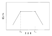
- FIG. 1 shows a schematic diagram of sound pressure frequency characteristics of an arbitrary speaker.
- the sound pressure increases in proportion to the frequency in the low frequency region.
- the frequency at which the sound pressure is maximized is referred to as a primary resonance frequency (f 0 ).
- the primary resonance frequency is derived from the following equation (1).
- the primary resonance frequency is proportional to the spring constant (k) of the vibration part of the speaker.
- the spring constant is proportional to the elastic modulus of the vibration part. Therefore, if the elastic modulus of the vibration part is large, in other words, if a hard material is used for the vibration part, the primary resonance frequency increases. That is, in FIG. 1, the primary resonance frequency (f 0 ) shifts in the right direction (high frequency side).
- the speaker electrode can be formed of, for example, a conductive material obtained by blending a polymer binder with a conductive material.
- a conductive material obtained by blending a polymer binder with a conductive material.
- the elastic modulus of the conductive material is reduced, so that a flexible electrode can be formed.
- the electrical resistance of the electrode increases. If the electrical resistance of the electrode is large, it will be difficult to produce sound in the high frequency region, as will be described below.
- the electrode layer and the dielectric layer form a low-pass filter in which an electric resistance and a capacitor are connected in series in a pseudo manner. Therefore, the cutoff frequency (f c ) at which the output sound pressure is reduced by 3 db is derived by the following equation (2). As shown in equation (2), the cutoff frequency is inversely proportional to the electrical resistance (R) of the electrode and the capacitance (C) of the dielectric layer. Therefore, when the electrical resistance of the electrode is large, the cutoff frequency is small. That is, in FIG. 1, the cut-off frequency (f c ) shifts to the left (low frequency side). As a result, the sound pressure in the high frequency region becomes small.
- the present invention has been made in view of such circumstances, and is a polymer speaker that can be light and thin and can obtain a practical sound pressure in a wide frequency range from a low frequency to a high frequency. It is an issue to provide.
- a polymer speaker of the present invention is a polymer speaker comprising an electrostrictive element having a dielectric layer made of an elastomer or a resin and a plurality of electrode layers arranged on both front and back surfaces of the dielectric layer.
- the electrode layer is made of a conductive material containing a polymer binder and a conductive material and having an elastic modulus of 100 MPa or less, and the spring constant in the surface direction of the electrode layer is smaller than the spring constant in the surface direction of the dielectric layer,
- the electrode layer has a volume resistivity of 200 ⁇ ⁇ cm or less.
- the dielectric layer vibrates by changing the thickness of the dielectric layer according to the electrostatic attractive force between the electrode layers. .
- sound is generated from both the front and back sides of the electrostrictive element.
- the phase of the generated sound is the same on the front side and the back side of the electrostrictive element.
- the electrostrictive element includes an elastomer or resin dielectric layer and an electrode layer.
- the polymer speaker of the present invention is thinner and lighter than a conventional dynamic speaker unit having a permanent magnet or a voice coil. Moreover, it can be manufactured at a relatively low cost. As described above, the polymer speaker of the present invention is lightweight, thin, and relatively inexpensive.
- “Elastomer or resin” means that the base material of the dielectric layer is an elastomer or a resin. Therefore, in addition to the elastomer or the resin component, other components such as additives may be included. Elastomers include rubber and thermoplastic elastomers.
- the electrode layer of the polymer speaker of the present invention is formed from a conductive material including a polymer binder and a conductive material.
- the elastic modulus of the conductive material is 100 MPa or less, and the spring constant in the surface direction of the electrode layer is smaller than the spring constant in the surface direction of the dielectric layer.
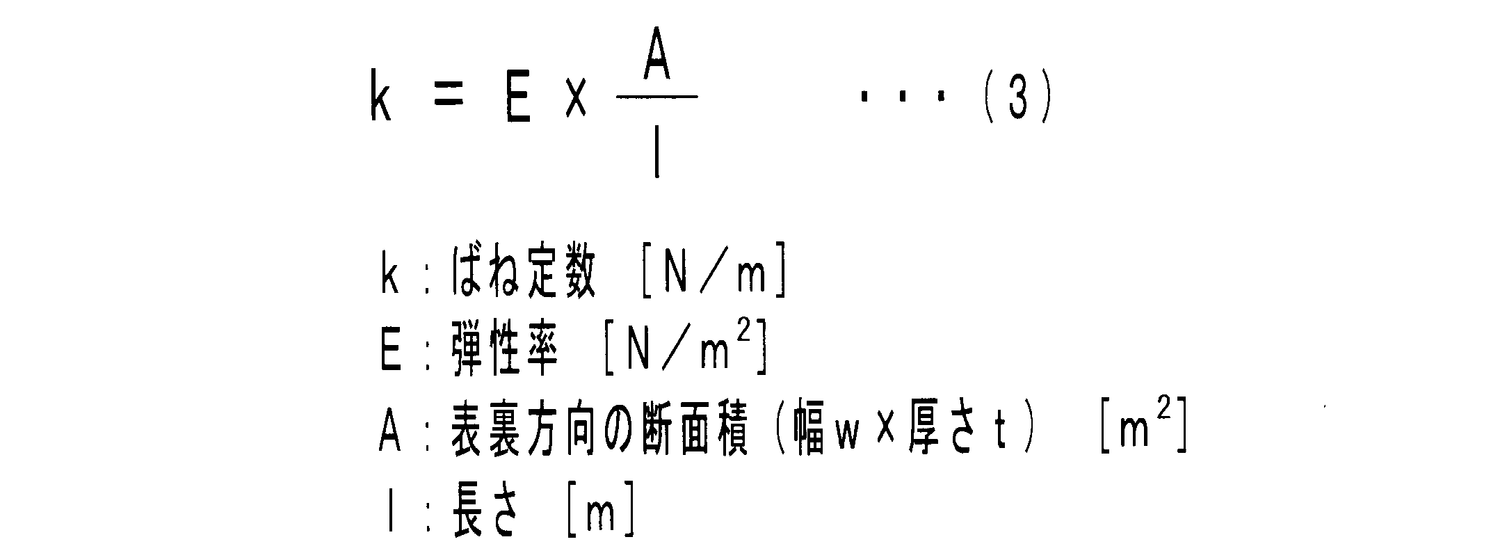
- the elastic modulus of the electrode layer and the dielectric layer is measured with a strip-shaped sample having a width (w) of 10 mm and a length (l) of 25 mm, and the spring constant in the surface direction of the electrode layer and the dielectric layer is It calculated by following Formula (3).
- the “surface direction” is a direction orthogonal to the front and back directions.
- the electrode layer is flexible because it satisfies the above two conditions. Therefore, the electrode layer is less likely to inhibit expansion and contraction of the dielectric layer, and is less likely to crack even if it is stretched.
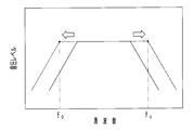
- the primary resonance frequency in the electrostrictive element is small. That is, as shown by a dotted line in FIG. 2, the primary resonance frequency (f 0 ) shifts to the left (low frequency side). For this reason, according to the polymer speaker of the present invention, it is possible to output the sound on the lower frequency side and increase the sound pressure in the low frequency region.
- the volume resistivity of the electrode layer of the polymer speaker of the present invention is 200 ⁇ ⁇ cm or less. Since the electrical resistance of the electrode layer is small, the cutoff frequency is increased. That is, as indicated by a one-dot chain line in FIG. 2, the cutoff frequency (f c ) shifts to the right (high frequency side). For this reason, according to the polymer speaker of the present invention, it is possible to output a sound on a higher frequency side and increase the sound pressure in the high frequency region.
- the reproducible frequency region can be expanded by widening the interval between the primary resonance frequency and the cutoff frequency. That is, a large sound pressure can be obtained in a wide frequency range from a low frequency to a high frequency.
- FIG. 4 is a sectional view taken along line IV-IV in FIG. 3.
- SYMBOLS 1 Polymer speaker, 10: Electrostrictive element, 11: Dielectric layer, 12a, 12b: Electrode layer, 120a, 120b: Terminal part, 20a: Front side frame, 20b: Back side frame, 21: Bolt, 22: Nut, 30 : DC bias power supply, 31: AC power supply.
- FIG. 3 shows a perspective view of the polymer speaker of the present embodiment.
- FIG. 4 shows a sectional view taken along the line IV-IV in FIG.
- the polymer speaker 1 includes an electrostrictive element 10, a front frame 20a, and a back frame 20b.
- the front side frame 20a and the back side frame 20b are each made of resin and have a ring shape.
- the front side frame 20a and the back side frame 20b are disposed to face each other with the peripheral edge portion of the electrostrictive element 10 interposed therebetween.
- the front side frame 20 a and the back side frame 20 b are fixed by eight bolts 21 and eight nuts 22.
- the set of “bolt 21 -nut 22” is arranged in the circumferential direction of the polymer speaker 1 with a predetermined interval.
- the bolt 21 penetrates from the front surface of the front frame 20a to the rear surface of the back frame 20b.
- the nut 22 is screwed to the penetrating end of the bolt 21.
- the electrostrictive element 10 is interposed between the front side frame 20a and the back side frame 20b.
- the electrostrictive element 10 includes a dielectric layer 11 and a pair of electrode layers 12a and 12b.
- the dielectric layer 11 is made of hydrogenated nitrile rubber (H-NBR) having an elastic modulus of 3.5 MPa, and has a circular thin film shape.
- the spring constant in the surface direction of the dielectric layer 11 is 75.6 N / m.
- the electrode layers 12a and 12b are both made of a conductive material containing acrylic rubber and ketjen black.
- the elastic modulus of the conductive material is 1.5 MPa.
- the electrode layers 12a and 12b have a spring constant in the surface direction of 3 N / m and a volume resistivity of 14 ⁇ ⁇ cm.
- the electrode layers 12 a and 12 b each have a circular thin film shape having a smaller diameter than the dielectric layer 11.
- the electrode layers 12a and 12b are each disposed substantially concentrically with the dielectric layer 11.
- the electrode layers 12a and 12b have terminal portions 120a and 120b, respectively.
- the terminal portions 120a and 120b protrude from the outer peripheral edge above the electrode layers 12a and 12b in the diameter increasing direction, respectively.
- Each of the terminal portions 120a and 120b has a strip shape.
- a DC bias power supply 30 and an AC power supply 31 are connected to the terminal portions 120a and 120b through wiring.
- the manufacturing method of the polymer speaker of this embodiment is demonstrated.
- two release films are prepared, and a coating material containing a conductive material is printed on the surface of one film to form the electrode layer 12a.
- the electrode layer 12b is formed on the surface of the other film.
- one film is bonded to the surface of the dielectric layer 11, and the electrode layer 12 a formed on the film is transferred to the surface of the dielectric layer 11.
- the other film is bonded to the back surface of the dielectric layer 11, and the electrode layer 12 b formed on the film is transferred to the back surface of the dielectric layer 11.
- the two release films are peeled from the dielectric layer 11.
- the electrode layers 12a and 12b are formed on both the front and back surfaces of the dielectric layer 11, and the electrostrictive element 10 is manufactured.
- the peripheral portion of the electrostrictive element 10 is sandwiched between the front frame 20a and the back frame 20b.
- the front side frame 20 a and the back side frame 20 b are fixed by the eight bolts 21 and the eight nuts 22. In this way, the polymer speaker 1 is manufactured.
- the electrostrictive element 10 includes an elastomeric dielectric layer 11 and electrode layers 12a and 12b formed on both front and back surfaces.
- the polymer speaker 1 is thinner and lighter than a conventional dynamic speaker unit having a permanent magnet or a voice coil. Moreover, it can be manufactured at a relatively low cost. Furthermore, the polymer speaker 1 does not require an enclosure. Therefore, the polymer speaker 1 is light and thin and relatively inexpensive.
- the dielectric layer 11 is made of H-NBR having an elastic modulus of 20 MPa or less. For this reason, the dielectric layer 11 is flexible and excellent in stretchability.
- the electrode layers 12a and 12b are made of a conductive material containing acrylic rubber as a polymer binder and having an elastic modulus of 10 MPa or less.
- the spring constant in the surface direction of the electrode layers 12a and 12b is 3 N / m, which is smaller than the spring constant in the surface direction of the dielectric layer 11 (75.6 N / m). For this reason, the electrode layers 12 a and 12 b are also flexible and can be expanded and contracted integrally with the dielectric layer 11.
- the electrode layers 12a and 12b are unlikely to hinder the movement of the dielectric layer 11, and are less likely to crack even when stretched.
- the spring constant in the surface direction of the electrode layers 12a and 12b is small, and the spring constant in the surface direction of the electrostrictive element 10 is also 3000 N / m or less. For this reason, the primary resonant frequency in the electrostrictive element 10 becomes small. Therefore, the polymer speaker 1 can output a sound on the lower frequency side, and the sound pressure in the low frequency region is increased.
- the volume resistivity of the electrode layers 12a and 12b is 200 ⁇ ⁇ cm or less. Since the electrical resistance of the electrode layers 12a and 12b is small, the cutoff frequency is increased. Therefore, the polymer speaker 1 can output a higher frequency sound, and the sound pressure in the high frequency region is increased. Thus, according to the polymer speaker 1, a large sound pressure can be obtained in a wide frequency range from a low frequency to a high frequency.
- the electrostrictive element in the polymer speaker of the present invention has an elastomer or resin dielectric layer and a plurality of electrode layers arranged on both the front and back surfaces of the dielectric layer.
- Suitable elastomers for the dielectric layer include hydrogenated nitrile rubber (H-NBR), nitrile rubber (NBR), silicone rubber, ethylene-propylene-diene rubber (EPDM), acrylic rubber, urethane rubber, epichlorohydrin rubber, chlorosulfone. And chlorinated polyethylene.
- H-NBR hydrogenated nitrile rubber
- NBR nitrile rubber
- EPDM ethylene-propylene-diene rubber
- acrylic rubber urethane rubber
- epichlorohydrin rubber chlorosulfone.
- chlorinated polyethylene chlorinated polyethylene.
- an elastomer modified by introducing a functional group such as epoxidized natural rubber, carboxyl group-modified hydrogenated nitrile rubber (XH-NBR), or the like may be used.
- XH-NBR carboxyl group-modified hydrogenated nitrile rubber
- the resin suitable for the dielectric layer examples include polyethylene, polypropylene, polyurethane, polystyrene (including cross-linked expanded polystyrene), polyvinyl chloride, vinylidene chloride copolymer, ethylene-vinyl acetate copolymer, and the like.
- an elastomer material having an elastic modulus of 20 MPa or less for the dielectric layer from the viewpoint of making the dielectric layer flexible and expanding a region having a large sound pressure to the low frequency side. Further, when the thickness of the dielectric layer is reduced, more electric charges can be stored, so that the output sound pressure can be increased. In addition, the spring constant in the surface direction of the dielectric layer can be reduced.
- the dielectric layer may contain other components such as additives in addition to the elastomer or the resin component.
- an insulating inorganic filler can be blended from the viewpoint of increasing the dielectric breakdown resistance of the dielectric layer.
- the inorganic filler include silica, titanium oxide, barium titanate, calcium carbonate, clay, fired clay, and talc.
- the electrode layer is made of a conductive material including a polymer binder and a conductive material.
- a polymer binder an elastomer, oil, or the like can be used. From the viewpoint of forming a stretchable electrode layer, an elastomer is preferred.
- elastomers include silicone rubber, NBR, EPDM, natural rubber, styrene-butadiene rubber (SBR), acrylic rubber, urethane rubber, epichlorohydrin rubber, chlorosulfonated polyethylene, chlorinated polyethylene and other crosslinked rubber, and styrene-based elastomers.
- Examples include olefin-based, vinyl chloride-based, polyester-based, polyurethane-based, and polyamide-based thermoplastic elastomers. Moreover, you may use the elastomer modified
- the type of conductive material is not particularly limited. What is necessary is just to select suitably from carbon powders, such as carbon black, a carbon nanotube, and graphite, metal powders, such as silver, gold
- various shapes of conductive materials can be easily manufactured.
- the cost of the conductive material can be reduced.
- metal materials such as silver listed above may be used.
- carbon materials such as carbon black, metal oxides such as calcium carbonate, titanium dioxide, aluminum oxide, and barium titanate, inorganic substances such as silica, resins such as acrylic and urethane, and the like may be used.
- a conductive material may be used individually by 1 type, and 2 or more types may be mixed and used for it.
- the elastic modulus of the conductive material is 100 MPa or less. In order to form a more flexible electrode layer, the elastic modulus of the conductive material is desirably 10 MPa or less. On the other hand, the volume resistivity of the conductive material (electrode layer) is 200 ⁇ ⁇ cm or less. In order to reduce the electrical resistance of the electrode layer and increase the sound pressure in the high frequency region, the volume resistivity of the electrode layer is desirably 2 ⁇ ⁇ cm or less. What is necessary is just to determine the kind of conductive material, a particle diameter, a shape, a compounding quantity, etc. so that the elasticity modulus and electroconductivity of a conductive material can be made compatible.
- the conductive material may contain additives such as a dispersant, a reinforcing agent, a plasticizer, an anti-aging agent, and a colorant, if necessary, in addition to the polymer binder and the conductive material.
- a coating material is prepared by adding a conductive material and, if necessary, an additive to a polymer solution obtained by dissolving the polymer for the elastomer in a solvent, and stirring and mixing. be able to.
- An electrode layer may be formed by directly applying the prepared paint to both the front and back surfaces of the dielectric layer.
- an electrode layer may be formed by applying a paint to the releasable film, and the formed electrode layer may be transferred to both the front and back surfaces of the dielectric layer.
- the coating method of the paint various known methods can be adopted. For example, in addition to printing methods such as inkjet printing, flexographic printing, gravure printing, screen printing, pad printing, and lithography, dipping, spraying, bar coating, and the like can be given. For example, when a printing method is employed, it is possible to easily separate the applied part and the non-applied part. Also, printing of large areas, thin lines, and complicated shapes is easy. Among the printing methods, a screen printing method is preferable because a highly viscous paint can be used and the coating thickness can be easily adjusted.
- the spring constant in the surface direction of the electrode layer is smaller than the spring constant in the surface direction of the dielectric layer.
- the spring constant of the electrostrictive element is preferably 3000 N / m or less.
- the spring constant of the electrostrictive element is calculated by the sum of the spring constant in the surface direction of the electrode layer and the spring constant in the surface direction of the dielectric layer.
- the number of dielectric layers and electrode layers constituting the electrostrictive element is not particularly limited.
- one electrode layer can be disposed on each of the front and back surfaces of one dielectric layer.
- a plurality of dielectric layers may be stacked via electrode layers. In this case, the deformation amount of the electrostrictive element with respect to the applied voltage is increased, and the output sound pressure can be increased.
- the electrostrictive element may be fixed to a support member such as a frame with the dielectric layer extended in the plane direction.
- the size and shape of the electrode layer are not particularly limited as long as a voltage can be applied to the dielectric layer.
- the electrode layer may be disposed so as to cover the entire surface of the dielectric layer.
- a plurality of electrode layers such as a band shape and a ring shape may be arranged on both the front and back surfaces of the dielectric layer.
- an overlapping portion of the electrode layer on the surface of the dielectric layer, the dielectric layer, and the electrode layer on the back surface of the dielectric layer functions as a speaker unit that outputs sound.
- the larger the area of the speaker part (overlapping part) the greater the capacitance.
- the cut-off frequency is shifted to the low frequency side, and the sound pressure in the low frequency region is increased. Therefore, by adjusting the arrangement pattern of the electrode layers, a plurality of speaker units capable of reproducing sounds in different frequency regions may be set in one polymer speaker.
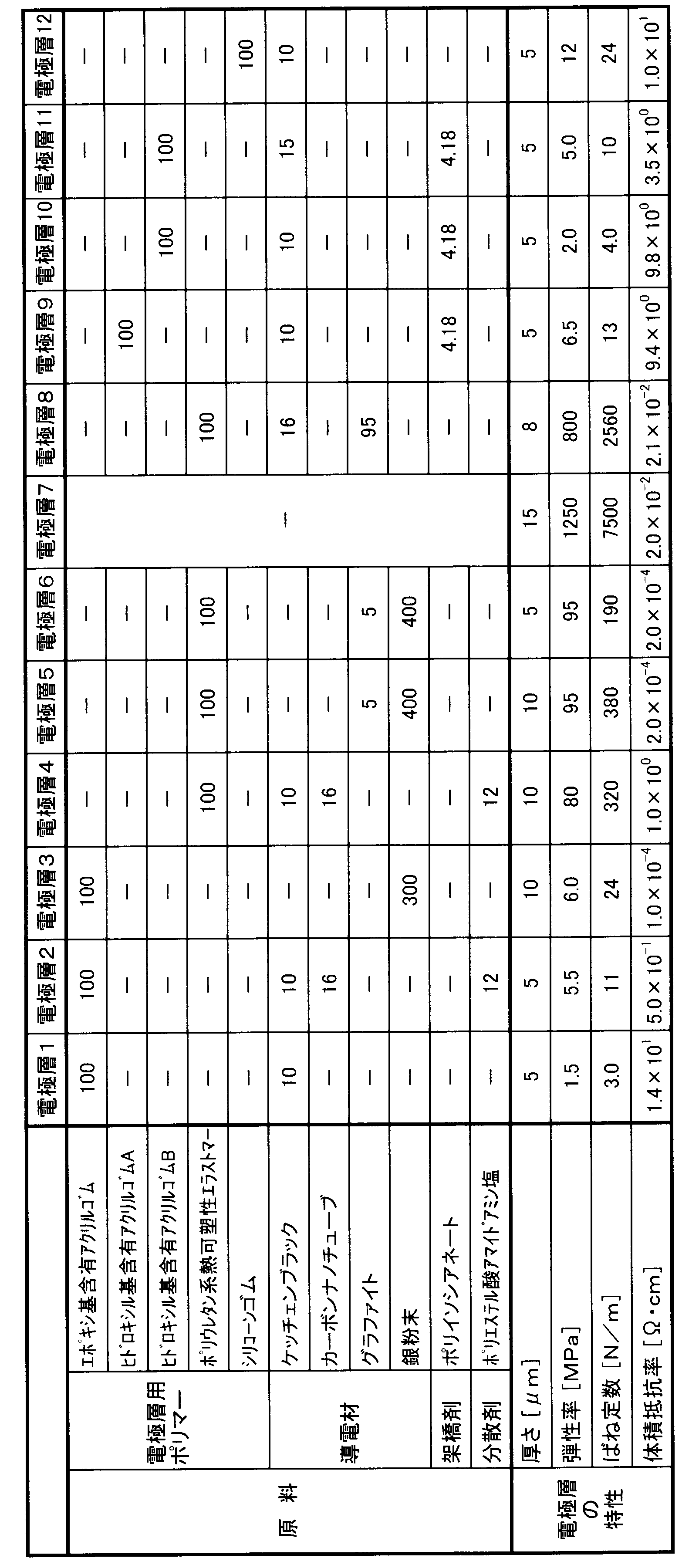
- Electrode layer> [Manufacture of electrode layers] Various electrode layers were produced from the polymer for electrode layers, conductive materials and the like shown in Table 1 below.
- the electrode layer polymer was dissolved in 1000 parts by mass of a solvent to prepare a polymer solution.
- a solvent butyl cellosolve acetate (BCA) was used for Examples 1 to 11, and toluene was used for Example 12.
- BCA butyl cellosolve acetate
- a conductive material was added to the prepared polymer solution at a predetermined mass ratio and dispersed to prepare a paint.
- the conductive material added with silver powder was dispersed with a three-roll, and the others were dispersed with a bead mill.
- the polyester acid amide amine salt was also added as a dispersing agent with the electrically conductive material.
- a polyisocyanate as a crosslinking agent was added to the polymer solution.
- the prepared paint was screen-printed on the surface of a base material made of acrylic resin and heated at 150 ° C. for about 1 hour to produce a thin-film electrode layer.
- the electrode layer 7 was manufactured by screen printing a commercially available carbon paste (“JELCON CH-8” manufactured by Jujo Chemical Co., Ltd.) for comparison.
- the thickness of the manufactured electrode layer is as shown in Table 1.
- Epoxy group-containing acrylic rubber “Nipol (registered trademark) AR42W” manufactured by Nippon Zeon Co., Ltd.
- Hydroxyl group-containing acrylic rubber A copolymer of n-ethyl acrylate (98% by mass) and 2-hydroxyethyl methacrylate (2% by mass) (mass molecular weight is about 900,000).
- Hydroxyl group-containing acrylic rubber B copolymer of n-butyl acrylate (98% by mass) and 2-hydroxyethyl methacrylate (2% by mass) (mass molecular weight is about 900,000).
- Polyurethane thermoplastic elastomer “Nipporan (registered trademark) 5193” manufactured by Nippon Polyurethane Industry Co., Ltd. Silicone rubber: “KE-1935” manufactured by Shin-Etsu Chemical Co., Ltd.
- Crosslinking agent “Coronate (registered trademark) HL” manufactured by Nippon Polyurethane Industry Co., Ltd.
- volume resistivity of the manufactured electrode layer was measured according to the parallel terminal electrode method of JIS K6271 (2008).
- Table 1 shows the volume resistivity of the electrode layer.
- ⁇ Dielectric layer> [Manufacture of dielectric layers] Various dielectric layers were produced from the dielectric layer polymers shown in Table 2 below.
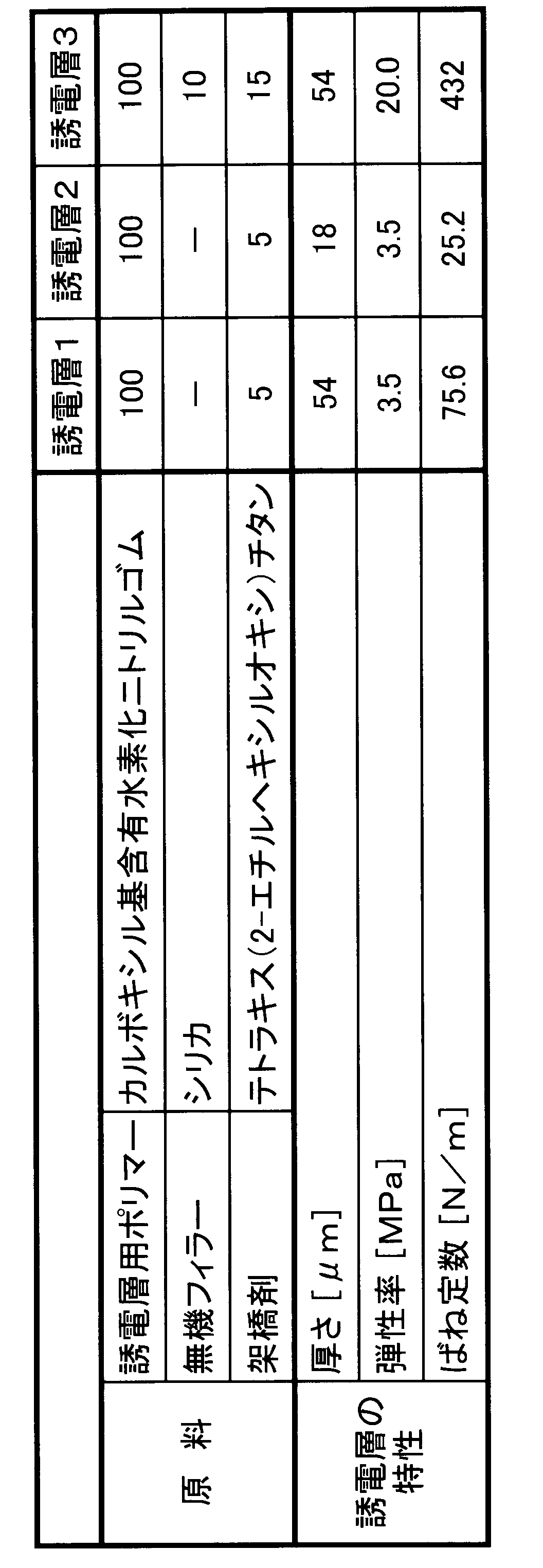
- a carboxyl group-containing hydrogenated nitrile rubber polymer (“Terban (registered trademark) XT8889” manufactured by LANXESS) was dissolved in acetylacetone.
- the dielectric layer 3 first, the same polymer and silica (wet silica “Nipsil (registered trademark) VN3” manufactured by Tosoh Silica Co., Ltd., pH 5.5 to 6.5, specific surface area 240 m 2 / g), A rubber composition was prepared by kneading with a roll kneader.
- the prepared rubber composition was dissolved in acetylacetone. Next, the organometallic compound tetrakis (2-ethylhexyloxy) titanium was added to the obtained polymer solution and mixed. Then, the mixed solution was screen-printed on the surface of an acrylic resin substrate and heated at 150 ° C. for about 1 hour to produce a thin film dielectric layer.
- the thickness of the manufactured dielectric layer is as shown in Table 2.
- the manufactured dielectric layer was cut into a strip shape having a width (w) of 10 mm and a length (l) of 25 mm to prepare a sample.
- the sample was subjected to a tensile test according to JIS K7127 (1999), and the elastic modulus was calculated from the obtained stress-elongation curve.
- the calculated elastic modulus was substituted into the above equation (3) to calculate the spring constant in the surface direction of the sample.
- Table 2 shows the elastic modulus and spring constant of the dielectric layer.
- Electrostrictive element Various electrostrictive elements were manufactured by appropriately combining the manufactured electrode layers and dielectric layers. First, the electrode layer was cut out into a circular shape having a diameter of 50 mm together with the base material. Next, the electrode layer was attached to the front and back surfaces of the dielectric layer peeled from the base material together with the base material. Then, the substrate was peeled from the electrode layer to produce an electrostrictive element composed of electrode layer / dielectric layer / electrode layer. The same type of electrode layer was attached to both the front and back surfaces of the dielectric layer. The spring constant of the electrostrictive element was calculated from the sum of the spring constant of the dielectric layer and the spring constant of the two electrode layers. Moreover, the surface resistivity of the electrostrictive element was measured according to the double ring electrode method of JIS K6271 (2008). The spring constant and surface resistivity of the electrostrictive element are shown in Table 3 below.
- the elastic modulus of the electrode layer is 10 MPa or less
- the spring constant of the electrode layer is smaller than the spring constant of the dielectric layer
- the spring constant of the electrostrictive element is 120 N / m or less
- the electrostrictive elements of Examples 2, 3, 5, and 7 to 9 including the electrode layers 2 to 6 having a volume resistivity of 2 ⁇ ⁇ cm or less have a higher frequency than the electrostrictive elements of the other examples. The sound pressure has increased. From this result, it can be seen that reducing the volume resistivity of the electrode layer is effective in increasing the sound pressure at high frequencies.
- the polymer speaker of the present invention can be used as, for example, an automobile headrest speaker, seat speaker, ceiling speaker, floor speaker, instrument panel speaker, door speaker and the like. Of course, you may arrange
Landscapes
- Chemical & Material Sciences (AREA)
- Physics & Mathematics (AREA)
- Engineering & Computer Science (AREA)
- Acoustics & Sound (AREA)
- Signal Processing (AREA)
- Health & Medical Sciences (AREA)
- Chemical Kinetics & Catalysis (AREA)
- Medicinal Chemistry (AREA)
- Polymers & Plastics (AREA)
- Organic Chemistry (AREA)
- Piezo-Electric Transducers For Audible Bands (AREA)
- Electrostatic, Electromagnetic, Magneto- Strictive, And Variable-Resistance Transducers (AREA)
Abstract
Description


[構成]
まず、本発明の一実施形態である高分子スピーカの構成を説明する。図3に、本実施形態の高分子スピーカの斜視図を示す。図4に、図1のIV-IV断面図を示す。図3、図4に示すように、高分子スピーカ1は、電歪素子10と、表側フレーム20aと、裏側フレーム20bと、を備えている。
次に、本実施形態の高分子スピーカの製造方法について説明する。まず、離型性フィルムを二枚準備して、一方のフィルムの表面に導電材料を含む塗料を印刷して、電極層12aを形成する。同様に、他方のフィルムの表面に、電極層12bを形成する。次に、誘電層11の表面に一方のフィルムを貼り合わせ、当該フィルムに形成された電極層12aを、誘電層11の表面に転写する。また、誘電層11の裏面に他方のフィルムを貼り合わせ、当該フィルムに形成された電極層12bを、誘電層11の裏面に転写する。それから、二枚の離型性フィルムを、誘電層11から剥離する。このようにして、誘電層11の表裏両面に電極層12a、12bを形成し、電歪素子10を作製する。次に、電歪素子10の周縁部を、表側フレーム20aと裏側フレーム20bとにより、挟持する。この状態で、表側フレーム20aと裏側フレーム20bとを、八つのボルト21、八つのナット22により、固定する。このようにして、高分子スピーカ1を製造する。
次に、本実施形態の高分子スピーカの動きについて説明する。初期状態において、電極層12a、12bには、直流バイアス電源30から所定のバイアス電圧が印加されている。この状態で、交流電源31から、再生対象となる音声に基づく交流電圧を、電極層12a、12bに印加する。すると、誘電層11の膜厚の変化により、図4に白抜き矢印で示すように、電歪素子10が前後方向に振動する。これにより、空気が振動し、音声が発生する。
次に、本実施形態の高分子スピーカの作用効果について説明する。本実施形態の高分子スピーカ1において、電歪素子10は、エラストマー製の誘電層11と、その表裏両面に形成された電極層12a、12bと、からなる。このため、高分子スピーカ1は、永久磁石やボイスコイルを有する従来のダイナミック型スピーカユニットと比較して、薄く軽量である。また、比較的低コストで製造することができる。さらに、高分子スピーカ1は、エンクロージャーを必要としない。したがって、高分子スピーカ1は、軽量かつ薄型であり、比較的安価である。
本発明の高分子スピーカにおける電歪素子は、エラストマーまたは樹脂製の誘電層と、該誘電層の表裏両面に配置される複数の電極層と、を有する。
[電極層の製造]
下記表1に示す電極層用ポリマー、導電材等から、種々の電極層を製造した。まず、電極層用ポリマーを、溶剤1000質量部に溶解し、ポリマー溶液を調製した。溶剤としては、実施例1~11についてはブチルセロソルブアセテート(BCA)を、実施例12についてはトルエンを使用した。次に、調製したポリマー溶液に、導電材を所定の質量割合で添加し、分散させて、塗料を調製した。導電材として銀粉末を添加したものについては、三本ロールにて分散させ、それ以外については、ビーズミルにて分散させた。また、電極層2、4については、導電材と共に、分散剤としてポリエステル酸アマイドアミン塩も添加した。電極層9~11については、ポリマー溶液に、架橋剤のポリイソシアネートを添加した。それから、調製した塗料を、アクリル樹脂製の基材表面にスクリーン印刷し、150℃で約1時間加熱して、薄膜状の電極層を製造した。電極層7については、比較のため、市販のカーボンペースト(十条ケミカル(株)製「JELCON CH-8」)を、基材表面にスクリーン印刷して、製造した。
エポキシ基含有アクリルゴム:日本ゼオン(株)製「Nipol(登録商標)AR42W」。
ヒドロキシル基含有アクリルゴムA:n-エチルアクリレート(98質量%)と2-ヒドロキシエチルメタクリレート(2質量%)との共重合体(質量分子量は90万程度)。
ヒドロキシル基含有アクリルゴムB:n-ブチルアクリレート(98質量%)と2-ヒドロキシエチルメタクリレート(2質量%)との共重合体(質量分子量は90万程度)。
ポリウレタン系熱可塑性エラストマー:日本ポリウレタン工業(株)製「ニッポラン(登録商標)5193」。
シリコーンゴム:信越化学工業(株)製「KE-1935」。
架橋剤:日本ポリウレタン工業(株)製「コロネート(登録商標)HL」。
(1)ばね定数の算出
製造した電極層を、幅(w)10mm、長さ(l)25mmの短冊状に切り出して、試料を作製した。そして、当該試料について、JIS K7127(1999)に準じた引張試験を行い、得られた応力-伸び曲線から、弾性率を算出した。また、算出した弾性率を前出式(3)に代入して、当該試料の面方向のばね定数を算出した。表1に、電極層の弾性率およびばね定数を示す。
製造した電極層の体積抵抗率を、JIS K6271(2008)の平行端子電極法に準じて測定した。表1に、電極層の体積抵抗率を示す。
[誘電層の製造]
下記表2に示す誘電層用ポリマー等から、種々の誘電層を製造した。誘電層1、2については、まず、カルボキシル基含有水素化ニトリルゴムポリマー(ランクセス社製「テルバン(登録商標)XT8889」)を、アセチルアセトンに溶解した。誘電層3については、まず、同ポリマーと、シリカ(東ソー・シリカ(株)製湿式シリカ「Nipsil(登録商標)VN3」、pH5.5~6.5、比表面積240m2/g)と、をロール練り機にて混練りし、ゴム組成物を調製した。そして、調製したゴム組成物を、アセチルアセトンに溶解した。次に、得られたポリマー溶液に、有機金属化合物のテトラキス(2-エチルヘキシルオキシ)チタンを添加して、混合した。それから、混合溶液を、アクリル樹脂製の基材表面にスクリーン印刷し、150℃で約1時間加熱して、薄膜状の誘電層を製造した。製造した誘電層の厚さは、表2に示す通りである。
製造した誘電層を、幅(w)10mm、長さ(l)25mmの短冊状に切り出して、試料を作製した。そして、当該試料について、JIS K7127(1999)に準じた引張試験を行い、得られた応力-伸び曲線から、弾性率を算出した。また、算出した弾性率を前出式(3)に代入して、当該試料の面方向のばね定数を算出した。表2に、誘電層の弾性率およびばね定数を示す。
製造した電極層と誘電層とを適宜組み合わせて、種々の電歪素子を製造した。まず、電極層を、基材ごと直径50mmの円形状に切り出した。次に、基材から剥離した誘電層の表面および裏面に、各々、電極層を基材ごと貼着した。それから、電極層から基材を剥離して、電極層/誘電層/電極層からなる電歪素子を製造した。誘電層の表裏両面には、同じ種類の電極層を貼着した。電歪素子のばね定数を、誘電層のばね定数と、二つの電極層のばね定数と、の和から算出した。また、電歪素子の表面抵抗率を、JIS K6271(2008)の二重リング電極法に準じて測定した。電歪素子のばね定数および表面抵抗率を、下記表3に示す。
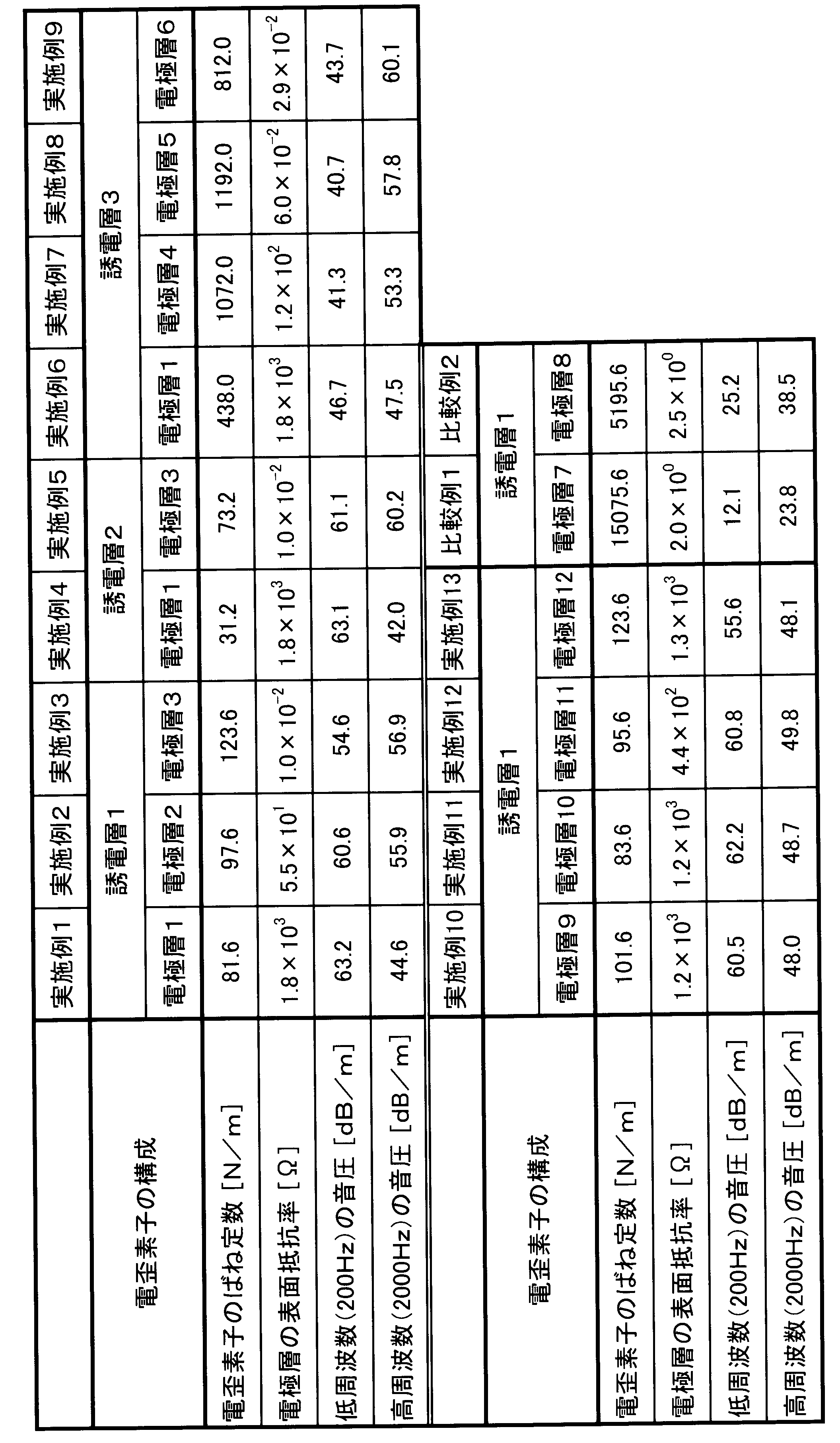
製造した電歪素子に、誘電層の厚さに対して30V/μmの直流バイアス電圧を印加した。この状態で、低周波数(200Hz)の交流電圧(3V/μm)を印加して、出力される音圧を測定した。同様に、高周波数(2000Hz)の交流電圧を印加して、出力される音圧を測定した。結果を上記表3にまとめて示す。
Claims (6)
- エラストマーまたは樹脂製の誘電層と、該誘電層の表裏両面に配置される複数の電極層と、を有する電歪素子を備える高分子スピーカであって、
該電極層は、高分子バインダーおよび導電材を含み弾性率が100MPa以下の導電材料からなり、該電極層の面方向のばね定数は該誘電層の面方向のばね定数より小さく、該電極層の体積抵抗率は200Ω・cm以下であることを特徴とする高分子スピーカ。 - 前記誘電層の前記ばね定数と前記電極層の前記ばね定数との和である前記電歪素子のばね定数は、3000N/m以下である請求項1に記載の高分子スピーカ。
- 前記導電材料の前記高分子バインダーは、エラストマーである請求項1または請求項2に記載の高分子スピーカ。
- 前記誘電層は、弾性率が20MPa以下のエラストマー製である請求項1ないし請求項3のいずれかに記載の高分子スピーカ。
- 前記導電材料の弾性率は、10MPa以下である請求項1ないし請求項4のいずれかに記載の高分子スピーカ。
- 前記電極層の体積抵抗率は、2Ω・cm以下である請求項1ないし請求項5のいずれかに記載の高分子スピーカ。
Priority Applications (5)
| Application Number | Priority Date | Filing Date | Title |
|---|---|---|---|
| KR1020147009128A KR101514620B1 (ko) | 2011-11-29 | 2012-11-27 | 고분자 스피커 |
| JP2013547159A JP5637521B2 (ja) | 2011-11-29 | 2012-11-27 | 高分子スピーカ |
| EP12852704.1A EP2787747B1 (en) | 2011-11-29 | 2012-11-27 | Polymer speaker |
| CN201280026182.9A CN103583056B (zh) | 2011-11-29 | 2012-11-27 | 高分子扬声器 |
| US14/016,621 US8958581B2 (en) | 2011-11-29 | 2013-09-03 | Polymer speaker |
Applications Claiming Priority (2)
| Application Number | Priority Date | Filing Date | Title |
|---|---|---|---|
| JP2011259892 | 2011-11-29 | ||
| JP2011-259892 | 2011-11-29 |
Related Child Applications (1)
| Application Number | Title | Priority Date | Filing Date |
|---|---|---|---|
| US14/016,621 Continuation US8958581B2 (en) | 2011-11-29 | 2013-09-03 | Polymer speaker |
Publications (1)
| Publication Number | Publication Date |
|---|---|
| WO2013080962A1 true WO2013080962A1 (ja) | 2013-06-06 |
Family
ID=48535416
Family Applications (1)
| Application Number | Title | Priority Date | Filing Date |
|---|---|---|---|
| PCT/JP2012/080598 Ceased WO2013080962A1 (ja) | 2011-11-29 | 2012-11-27 | 高分子スピーカ |
Country Status (6)
| Country | Link |
|---|---|
| US (1) | US8958581B2 (ja) |
| EP (1) | EP2787747B1 (ja) |
| JP (2) | JP5637521B2 (ja) |
| KR (1) | KR101514620B1 (ja) |
| CN (1) | CN103583056B (ja) |
| WO (1) | WO2013080962A1 (ja) |
Families Citing this family (9)
| Publication number | Priority date | Publication date | Assignee | Title |
|---|---|---|---|---|
| DE112012006175B4 (de) * | 2012-03-30 | 2018-08-16 | Sumitomo Riko Company Limited | Lautsprecher |
| WO2014157684A1 (ja) * | 2013-03-29 | 2014-10-02 | 富士フイルム株式会社 | スピーカシステム |
| JP6071932B2 (ja) * | 2013-04-01 | 2017-02-01 | 富士フイルム株式会社 | 電気音響変換フィルム |
| WO2015133417A1 (ja) * | 2014-03-03 | 2015-09-11 | バンドー化学株式会社 | センサ装置及び伸縮構造体 |
| CN105916081B (zh) * | 2016-05-05 | 2019-10-08 | 歌尔股份有限公司 | 一种扬声器模组 |
| KR102325707B1 (ko) * | 2016-09-20 | 2021-11-11 | 오사카 유키가가쿠고교 가부시키가이샤 | (메타)아크릴계 도전성 재료 |
| WO2019107558A1 (ja) * | 2017-11-30 | 2019-06-06 | 住友理工株式会社 | トランスデューサ及びその製造方法 |
| JP7410935B2 (ja) | 2018-05-24 | 2024-01-10 | ザ リサーチ ファウンデーション フォー ザ ステイト ユニバーシティー オブ ニューヨーク | 容量性センサ |
| JP7641892B2 (ja) * | 2019-03-28 | 2025-03-07 | 住友理工株式会社 | 静電型トランスデューサおよび静電型トランスデューサユニット |
Citations (7)
| Publication number | Priority date | Publication date | Assignee | Title |
|---|---|---|---|---|
| JPS6352599A (ja) * | 1986-08-22 | 1988-03-05 | Sony Corp | 電気音響変換器用背極装置 |
| JP2001524278A (ja) | 1997-02-07 | 2001-11-27 | エス アール アイ・インターナショナル | 弾性誘電体ポリマフィルム音波アクチュエータ |
| JP2006005800A (ja) | 2004-06-18 | 2006-01-05 | Taiyo Yuden Co Ltd | 圧電スピーカ |
| JP2007074502A (ja) | 2005-09-08 | 2007-03-22 | Teijin Fibers Ltd | 音波発生機能を有する繊維積層構造体および繊維製品 |
| JP2007312094A (ja) | 2006-05-18 | 2007-11-29 | Viva Computer Co Ltd | スピーカシステム |
| JP2008270349A (ja) * | 2007-04-17 | 2008-11-06 | Mitsubishi Electric Corp | 電気二重層キャパシタ用電極及びその製造方法 |
| JP2011072112A (ja) | 2009-09-25 | 2011-04-07 | Tokai Rubber Ind Ltd | 誘電膜およびそれを用いたトランスデューサ |
Family Cites Families (14)
| Publication number | Priority date | Publication date | Assignee | Title |
|---|---|---|---|---|
| JP3233041B2 (ja) * | 1996-08-13 | 2001-11-26 | 株式会社村田製作所 | 圧電型電気音響変換器 |
| US7320457B2 (en) * | 1997-02-07 | 2008-01-22 | Sri International | Electroactive polymer devices for controlling fluid flow |
| US6261237B1 (en) * | 1998-08-20 | 2001-07-17 | Medacoustics, Inc. | Thin film piezoelectric polymer sensor |
| JP3489509B2 (ja) * | 1999-02-22 | 2004-01-19 | 株式会社村田製作所 | 電気音響変換器 |
| US7608989B2 (en) * | 1999-07-20 | 2009-10-27 | Sri International | Compliant electroactive polymer transducers for sonic applications |
| WO2005086528A1 (en) | 2004-03-04 | 2005-09-15 | Mirae Plasma Co., Ltd. | Method of manufacturing film-speaker using piezoelectric film and sound equipment with the same |
| JP2007028205A (ja) * | 2005-07-15 | 2007-02-01 | Sony Corp | 電気音響変換器およびその振動膜成型方法 |
| JP4737082B2 (ja) * | 2006-12-28 | 2011-07-27 | Tdk株式会社 | 圧電発音体 |
| JP4948323B2 (ja) * | 2007-08-17 | 2012-06-06 | 株式会社クラレ | 高分子柔軟電極が付されたエレクトロデバイス |
| JP5243775B2 (ja) * | 2007-11-14 | 2013-07-24 | 東海ゴム工業株式会社 | 誘電膜およびそれを用いたアクチュエータ、センサ、トランスデューサ |
| JP2009272978A (ja) * | 2008-05-09 | 2009-11-19 | Nippon Hoso Kyokai <Nhk> | フレキシブルスピーカ |
| JP5474331B2 (ja) * | 2008-10-30 | 2014-04-16 | 東海ゴム工業株式会社 | 誘電膜、およびそれを用いたアクチュエータ、センサ、トランスデューサ |
| JP5646259B2 (ja) | 2010-09-17 | 2014-12-24 | 住友理工株式会社 | エラストマー材料の製造方法 |
| WO2012059814A2 (en) * | 2010-10-14 | 2012-05-10 | Pio Corporation Nv | Electrostatic loudspeaker system |
-
2012
- 2012-11-27 EP EP12852704.1A patent/EP2787747B1/en active Active
- 2012-11-27 WO PCT/JP2012/080598 patent/WO2013080962A1/ja not_active Ceased
- 2012-11-27 JP JP2013547159A patent/JP5637521B2/ja active Active
- 2012-11-27 KR KR1020147009128A patent/KR101514620B1/ko not_active Expired - Fee Related
- 2012-11-27 CN CN201280026182.9A patent/CN103583056B/zh not_active Expired - Fee Related
-
2013
- 2013-09-03 US US14/016,621 patent/US8958581B2/en active Active
-
2014
- 2014-10-09 JP JP2014207995A patent/JP5807105B2/ja active Active
Patent Citations (7)
| Publication number | Priority date | Publication date | Assignee | Title |
|---|---|---|---|---|
| JPS6352599A (ja) * | 1986-08-22 | 1988-03-05 | Sony Corp | 電気音響変換器用背極装置 |
| JP2001524278A (ja) | 1997-02-07 | 2001-11-27 | エス アール アイ・インターナショナル | 弾性誘電体ポリマフィルム音波アクチュエータ |
| JP2006005800A (ja) | 2004-06-18 | 2006-01-05 | Taiyo Yuden Co Ltd | 圧電スピーカ |
| JP2007074502A (ja) | 2005-09-08 | 2007-03-22 | Teijin Fibers Ltd | 音波発生機能を有する繊維積層構造体および繊維製品 |
| JP2007312094A (ja) | 2006-05-18 | 2007-11-29 | Viva Computer Co Ltd | スピーカシステム |
| JP2008270349A (ja) * | 2007-04-17 | 2008-11-06 | Mitsubishi Electric Corp | 電気二重層キャパシタ用電極及びその製造方法 |
| JP2011072112A (ja) | 2009-09-25 | 2011-04-07 | Tokai Rubber Ind Ltd | 誘電膜およびそれを用いたトランスデューサ |
Non-Patent Citations (1)
| Title |
|---|
| See also references of EP2787747A4 |
Also Published As
| Publication number | Publication date |
|---|---|
| KR20140059290A (ko) | 2014-05-15 |
| EP2787747A4 (en) | 2015-06-03 |
| EP2787747A1 (en) | 2014-10-08 |
| US8958581B2 (en) | 2015-02-17 |
| CN103583056B (zh) | 2016-06-15 |
| JP2015006011A (ja) | 2015-01-08 |
| US20140003634A1 (en) | 2014-01-02 |
| CN103583056A (zh) | 2014-02-12 |
| KR101514620B1 (ko) | 2015-04-22 |
| JP5807105B2 (ja) | 2015-11-10 |
| JPWO2013080962A1 (ja) | 2015-04-27 |
| JP5637521B2 (ja) | 2014-12-10 |
| EP2787747B1 (en) | 2017-06-28 |
Similar Documents
| Publication | Publication Date | Title |
|---|---|---|
| JP5807105B2 (ja) | 高分子スピーカ | |
| JP5633769B1 (ja) | 柔軟なトランスデューサ | |
| US20140090884A1 (en) | Elastic conductive material | |
| US20150200039A1 (en) | Conductive material and transducer including the conductive material | |
| JPWO2013058237A1 (ja) | 誘電膜およびそれを用いたトランスデューサ | |
| JP5474473B2 (ja) | 誘電膜およびそれを用いたトランスデューサ | |
| WO2011001910A1 (ja) | 柔軟導電材料およびトランスデューサ | |
| US9288583B2 (en) | Speaker | |
| JP6249852B2 (ja) | 誘電膜の製造方法 | |
| CN108369462B (zh) | 触觉振动提示装置 | |
| WO2018207707A1 (ja) | アクチュエータ、駆動部材、触覚提示装置および駆動装置 | |
| JP2012248399A (ja) | 柔軟導電材料およびその製造方法 | |
| CN109863762B (zh) | 静电式换能器 | |
| JP6002524B2 (ja) | トランスデューサ | |
| JP5694877B2 (ja) | 高分子スピーカ | |
| WO2013175662A1 (ja) | スピーカー | |
| JP2014236565A (ja) | トランスデューサ | |
| JP5876279B2 (ja) | スピーカー | |
| CN116965059A (zh) | 层叠压电元件 | |
| EP4306225A1 (en) | Multilayer piezoelectric element | |
| JP6030831B2 (ja) | スピーカー |
Legal Events
| Date | Code | Title | Description |
|---|---|---|---|
| 121 | Ep: the epo has been informed by wipo that ep was designated in this application |
Ref document number: 12852704 Country of ref document: EP Kind code of ref document: A1 |
|
| REEP | Request for entry into the european phase |
Ref document number: 2012852704 Country of ref document: EP |
|
| ENP | Entry into the national phase |
Ref document number: 2013547159 Country of ref document: JP Kind code of ref document: A |
|
| ENP | Entry into the national phase |
Ref document number: 20147009128 Country of ref document: KR Kind code of ref document: A |
|
| NENP | Non-entry into the national phase |
Ref country code: DE |